Daewoo Nubira. Service manual - part 158


  Index      Daewoo     Daewoo Nubira - service and repair manual


Search            


Content   ..  156  157  158  159   ..


Daewoo Nubira. Service manual - part 158


1C – 90

I

DOHC ENGINE MECHANICAL

DAEWOO V–121 BL4

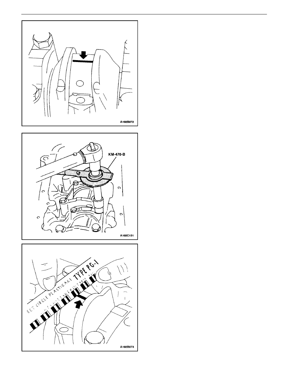
Inspection Procedure – Connecting Rods

1.  Coat the connecting rod bearings with engine oil.
2.  Install the upper connecting rod bearings into the

connecting rod journals.

3.  Install the lower connecting rod bearings into the

connecting rod bearing caps.

Important : Grease the connecting rod journals and lubri-
cate the connecting rod bearings slightly so that the plastic
gauging thread does not tear when the connecting rod
bearing caps are removed.

4.  Inspect all of the connecting rod bearing clearances

using a commercially available plastic gauging
(ductile plastic threads).

5.  Cut the plastic gauging threads to the length of the

bearing width. Lay them axially between the con-
necting rod journals and the connecting rod bear-
ings.

6.  Install the connecting rod bearing caps.
7.  Install the connecting rod bearing cap bolts.

Tighten

Tighten the connecting rod cap bolts to 35 N

S

m (26 lb–

ft). Using the angular torque gauge KM–470–B, tight-
en the connecting rod cap bolts to +45 degrees plus
one turn of 15 degrees.

8.  Remove the connecting rod bearing caps.
9.  Measure the width of the flattened plastic thread of

the plastic gauging using a ruler. (Plastic gauging is
available for different tolerance ranges.)

10.  Inspect the bearing clearance for permissible toler-

ance ranges. Refer to ”Engine Specifications”in this
section.

DOHC ENGINE MECHANICAL  1C – 91

DAEWOO V–121 BL4

GENERAL DESCRIPTION

AND SYSTEM OPERATION

CYLINDER HEAD AND GASKET

The cylinder head is made of an aluminum alloy and uses
cross–flow intake and exhaust ports. A spark plug is lo-
cated in the center of each combustion chamber. The cyl-
inder head houses the dual camshafts.

CRANKSHAFT

The crankshaft has eight integral weights which are cast
with it for balancing. Oil holes run through the center of the
crankshaft to supply oil to the connecting rods, the bear-
ings, the pistons, and the other components. The end
thrust load is taken by the thrust washers installed at the
center journal.

TIMING BELT

The timing belt coordinates and keeps the crankshaft and
the dual overhead camshafts synchronized. The timing
belt also turns the coolant pump. The timing belt and the
pulleys are toothed so that there is no slippage between
them. There are two idler pulleys. An automatic tensioner
pulley maintains the timing belt

s correct tension. The tim-

ing belt is made of a tough reinforced rubber similar to that
used on the serpentine drive belt and requires no lubrica-
tion.

OIL PUMP

The oil pump draws engine oil from the oil pan and feeds
it under pressure to the various parts of the engine. An oil
strainer is mounted before the inlet of the oil pump to re-
move impurities which could clog or damage the oil pump
or other engine components. When the crankshaft ro-
tates, the oil pump driven gear rotates. This causes the
space between the gears to constantly open and narrow,
pulling oil in from the oil pan when the space opens and
pumping the oil out to the engine as it narrows.

At high engine speeds, the oil pump supplies a much high-
er amount of oil than required for lubrication of the engine.
The oil pressure regulator prevents too much oil from en-
tering the engine lubrication passages. During normal oil
supply, a coil spring and valve keep the bypass closed, di-
recting all of the oil pumped to the engine. When the
amount of oil being pumped increases, the pressure be-
comes high enough to overcome the force of the spring.

This opens the valve of the oil pressure regulator, allowing
the excess oil to flow through the valve and drain back to
the oil pan.

OIL PAN

The engine oil pan is mounted to the bottom of the cylinder
block. The engine oil pan houses the crankcase and is
made of cast aluminum.

Engine oil is pumped from the oil pan by the oil pump. After
it passes through the oil filter, it is fed through two paths
to lubricate the cylinder block and the cylinder head. In one
path, the oil is pumped through oil passages in the crank-
shaft to the connecting rods, and to the pistons and cylin-
ders. It then drains back to the oil pan. In the second path,
the oil is pumped through passages to the camshaft. The
oil passes through the internal passage ways in the cam-
shafts to lubricate the valve assemblies before draining
back to the oil pan.

EXHAUST MANIFOLD

A single four–port, rear–takedown manifold is used. The
manifold is designed to direct escaping exhaust gases out
of the combustion chambers with a minimum of back pres-
sure. The oxygen sensor is mounted to the exhaust man-
ifold.

INTAKE MANIFOLD

The intakemanifold has four independent long ports and
utilizes an inertial supercharging effect to improve engine
torque at low and moderate speeds.

CAMSHAFTS

This engine is a dual overhead camshaft (DOHC) type,
which means there are two camshafts. One camshaft op-
erates the intake valves, and the other camshaft operates
the exhaust valves. The camshafts sit in journals on the
top of the engine (in the cylinder head) and are held in
place by camshaft caps. The camshaft journals of the cyl-
inder head are drilled for oil passages. Engine oil travels
to the camshafts under pressure where it lubricates each
camshaft journal. The oil returns to the oil pan through
drain holes in the cylinder head. The camshaft lobes are
machined into the solid camshaft to precisely open and
close the intake and the exhaust valves the proper dis-
tance at the correct time. The camshaft lobes are oiled by
splash action from pressurized oil escaping from the cam-
shaft journals.

TECHNICAL SERVICE BULLETIN

TECHNICAL SERVICE BULLETIN

Description:

Reference:

Prod. Dates:

Bulletin No.:

Model(s):

Date:

VIN Range:

Group:

TSB-004-01

All

August 3, 2001

N/A

Fuel Level Sensor Availability

Engine

N/A

N/A

General Manager
Service Manager

Technician(s)

Service Advisor

Body Shop Manager
Parts Manager

Circulate To:


Daewoo has determined that some Lanos, Nubira and Leganza models have experienced
incorrect fuel gauge readings caused by a faulty Fuel Level Sensor unit in the Fuel Tank.
Reported conditions include the Fuel Gauge failing to read above the “3/4” mark or below the
“1/4” mark, which is caused by the resistor card “wiper” wearing the Fuel Level Sensor
contacts prematurely resulting in a short or open circuit that triggers the false readings at the
Fuel Gauge.  The Fuel Level Sensor has been improved in all vehicles produced since
October 9, 2000 by coating the resistor card with a special lubricant to prevent premature
wear of the resistor card contacts. 

To simplify the repair, the Fuel Level Sensor is now available as a separate replacement part.
It is no longer necessary to replace the complete Fuel Pump Module to replace a faulty Fuel
Level Sensor.  Refer to TSB-005-01 for complete Fuel Level Sensor removal and
replacement procedures.

Important: Daewoo has also noted a small number of customer comments regarding the
rate of Fuel Gauge Indicator movement as compared to the actual amount of fuel used.  If the
Fuel Tank is filled to capacity, the vehicle may tend to travel more miles between the “Full”
indicator and the “1/2” mark than between the “1/2” mark and the “Empty” indicator.  This is a
normal characteristic of the Fuel Level Sensor which has not been revised to change this
characteristic.  Attempts to address this customer concern by replacing the Fuel Level Sensor
will not correct this condition.

Parts Information:

Vehicle

Part Name

Part Number

Qty. Required

Remarks

Lanos

Fuel Level Sensor

96388929

1

Nubira

Fuel Level Sensor

96388676

1

Leganza

Fuel Level Sensor

96405140

1

Note: Fuel Level Sensor units are not interchangeable between models.

If additional information is needed regarding this bulletin, please contact your District Parts &
Service Manager or the Daewoo Technical Assistance Center toll free at (877) 362-1234,
selection 1.

TECHNICAL SERVICE BULLETIN

TECHNICAL SERVICE BULLETIN

Description:

Reference:

Prod. Dates:

Bulletin No.:

Model(s):

Date:

VIN Range:

Group:

TSB-005-01

All

August 3, 2001

N/A

Fuel Level Sensor Procedures

Engine

N/A

N/A

General Manager
Service Manager

Technician(s)

Service Advisor

Body Shop Manager
Parts Manager

Circulate To:


Note: Ensure that the Ignition Switch is in the “OFF” position.

1. Remove the Rear Seat Cushion.

Lanos ONLY - Remove and retain the retaining bolt located at the front center of the Rear
Seat Cushion, then lift up the front edge of the cushion to release the two (2) retaining latches.

Nubira & Leganza - Lift up on the front edge of the Rear Seat Cushion to release the two
(2) retaining latches.

2. Remove the Rear Seat Bottom Cushion to gain access to the Fuel Tank.

3. Remove the Fuel Pump Module Access Cover.

This bulletin supplements Technical Service Bulletin #TSB-004-01 “Fuel Level Sensor
Availability” which identified specific customer concerns related to Lanos, Nubira and Leganza
models that have experienced incorrect fuel gauge readings caused by a faulty Fuel Level
Sensor unit in the Fuel Tank.

To simplify the repair, an improved Fuel Level Sensor is now available as a separate
replacement part.  It is no longer necessary to replace the complete Fuel Pump Module to
replace a faulty Fuel Level Sensor.

Included in this bulletin is a procedure for diagnosing the Fuel Level Sensor (commonly
referred to as a "Fuel Level Sending Unit") and the replacement procedure, if necessary,
which involves the partial disassembly of the Fuel Pump Module. 

Note: Fuel Level Sensor units are not interchangeable between models.

CAUTION: Removing components from a sealed fuel system exposes fuel vapors to

outside oxygen and possible sources of combustion. The fuel system is
under pressure which must first be relieved to avoid possible spillage or
fire when removing system components. A fuel system should only be
opened when absolutely necessary, and only in a properly ventilated area
after the prescribed diagnostic procedures have determined that fuel
system components must be removed. Special caution should be used
when removing components from a fuel tank or fuel system. Removal of
such components should only be done by an experienced, certified
technician and away from open flame (torches, lit cigarettes, heater pilots
or other flames however minor) or sparks (mechanical, electrical or
otherwise) that could cause fuel vapors to ignite.

FUEL LEVEL SENSOR DIAGNOSTIC PROCEDURE:


Content   ..  156  157  158  159   ..