Daewoo Nubira. Service manual - part 145


  Index      Daewoo     Daewoo Nubira - service and repair manual


Search            


Content   ..  143  144  145  146   ..


Daewoo Nubira. Service manual - part 145


1C – 14

I

DOHC ENGINE MECHANICAL

DAEWOO V–121 BL4

CYLINDER HEAD AND GASKET

Tools Required

KM–470–B Angular Torque Gauge
J–28467–B Engine Assembly Lift Support

Removal Procedure

1.  Remove the fuel pump fuse.
2.  Start the engine. After it stalls, crank the engine for

10 seconds to rid the fuel system of fuel pressure.

3.  Disconnect the negative battery cable.
4.  Disconnect the powertrain control module

(PCM)/engine control module (ECM) ground termi-
nal.

5.  Drain the engine coolant. Refer to Section 1D, En-

gine Cooling.

6.  Disconnect the intake air temperature sensor con-

nector.

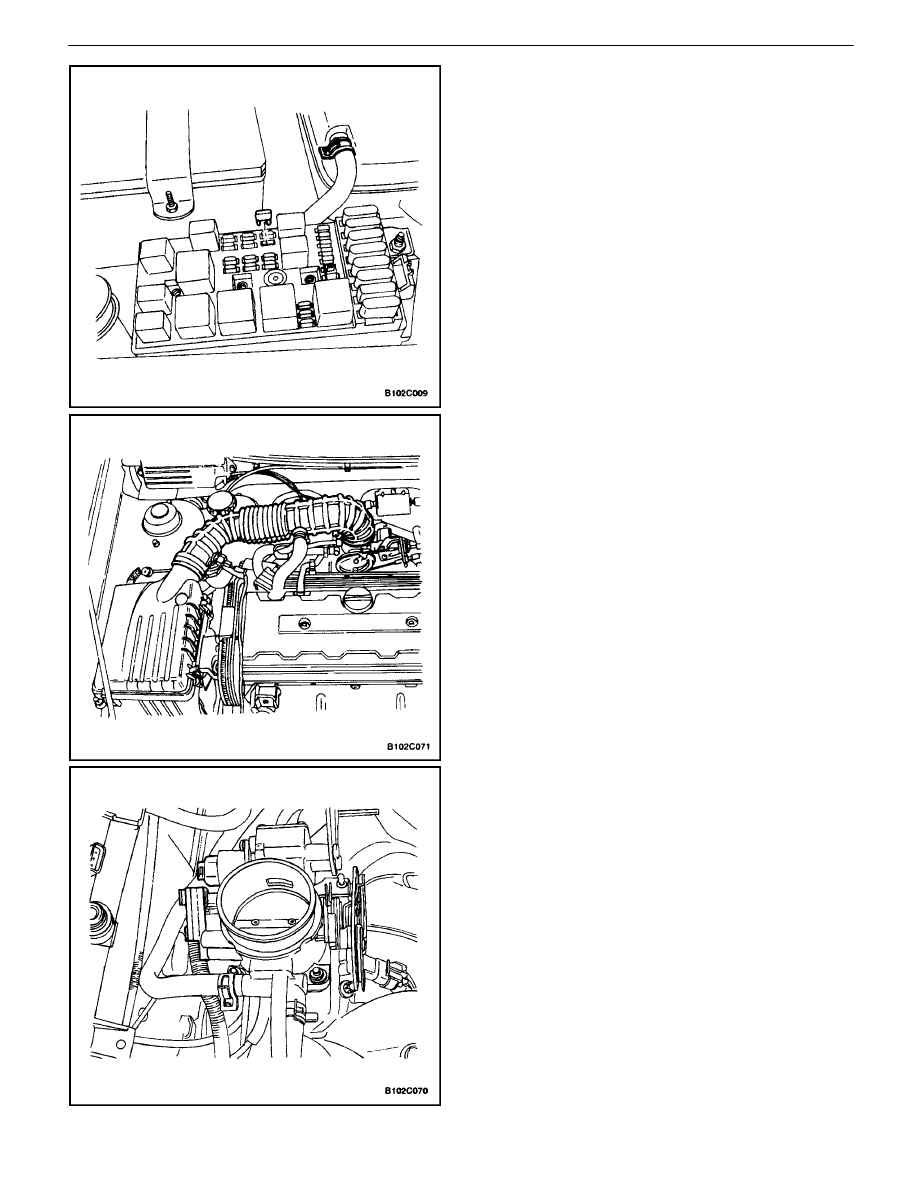
7.  Disconnect the breather tube from the valve cover.
8.  Disconnect the air intake tube from the throttle

body.

9.  Disconnect the electronic ignition system (EI sys-

tem) ignition coil connector.

10.  Disconnect the pre–converter oxygen sensor con-

nector.

11.  Disconnect the idle air control valve connector.
12.  Disconnect the throttle position sensor connector.
13.  Disconnect the engine coolant temperature sensor

connector.

14.  Disconnect the coolant temperature sensor connec-

tor.

15.  Disconnect the camshaft position sensor.

DOHC ENGINE MECHANICAL  1C – 15

DAEWOO V–121 BL4

16.  Remove the air filter housing bolts.
17.  Remove the air filter housing.
18.  Remove the right front wheel. Refer to Section 2E,

Tires and Wheels.

19.  Remove the right front splash shield.
20.  Install the engine assembly lift support J–28467–B.
21.  Remove the right engine mount bracket and bolts.

22.  Disconnect the upper radiator hose at the thermo-

stat housing.

23.  Remove the serpentine accessory drive belt. Refer

to Section 6B, Power Steering Pump.

24.  Remove the crankshaft pulley bolts.
25.  Remove the crankshaft pulley.

26.  Remove the front timing belt cover bolts.
27.  Remove the front timing belt cover.

1C – 16

I

DOHC ENGINE MECHANICAL

DAEWOO V–121 BL4

28.  Remove the timing belt. Refer to  ”Timing Belt” in

this section.

29.  Disconnect the breather tube at the valve cover.
30.  Remove the spark plug cover bolts.
31.  Remove the spark plug cover.
32.  Disconnect the ignition wires from the spark plugs.
33.  Remove the valve cover nuts.
34.  Remove the valve cover washers.
35.  Remove the valve cover and the valve cover gas-

ket.

Notice : Take extreme care to prevent any scratches,
nicks or damage to the camshafts.

36.  While holding the intake camshaft firmly in place,

remove the intake camshaft gear bolt.

37.  Remove the intake camshaft gear.
38.  While holding the exhaust camshaft firmly in place,

remove the exhaust camshaft gear bolt.

39.  Remove the exhaust camshaft gear.

40.  Remove the timing belt automatic tensioner bolts.
41.  Remove the timing belt automatic tensioner.

DOHC ENGINE MECHANICAL  1C – 17

DAEWOO V–121 BL4

42.  Remove the timing belt idler pulley bolt and nut.
43.  Remove the timing belt idler pulleys.
44.  Remove the engine mount bolts.
45.  Remove the engine mount.

46.  Remove the rear timing belt cover bolts.
47.  Remove the rear timing belt cover.

48.  Remove the auxiliary catalytic converter nuts at the

exhaust manifold.

49.  Disconnect all of the necessary vacuum hoses.


Content   ..  143  144  145  146   ..