Chery Tiggo 5 (T21). Service manual - part 518


  Index      Chery     Chery Tiggo 5 (T21) - service and repair manual 2014 year


Search            copyright infringement  


Content   ..  516  517  518  519   ..


Chery Tiggo 5 (T21). Service manual - part 518


48–

30

48

Rear Bumper Assembly

Removal

1. Turn off all the electrical equipment and ignition switch.
2. Disconnect the negative battery cable.
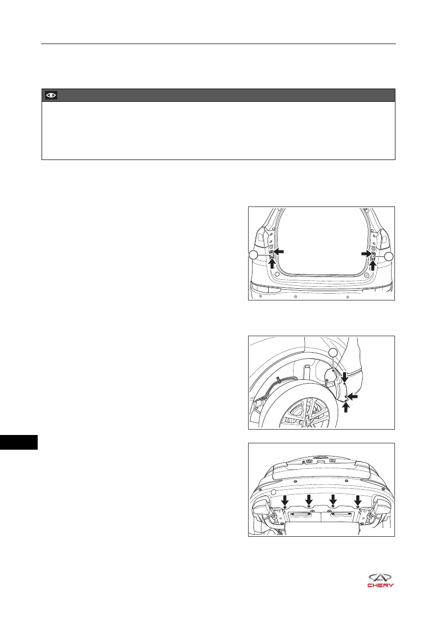
3. Remove the back door locating seat.

a. Remove 4 fixing bolts (arrow) from the back door 

locating seat.

(Tightening torque: 1.5 ± 1 N·m)

b. Remove the back door left locating seat (1) and back 

door right locating seat (2).

4. Remove the rear combination light assembly (fixed part) (

See page 35-74

).

5. Remove the rear bumper assembly.

a. Raise the vehicle with a lifter, and remove the fixing 

screw (1) between rear bumper assembly and rear 
wheel house protector assembly (take left side as an 
example).

(Tightening torque: 3 ± 1 N·m)

b. Remove 3 plastic clips (arrow) between rear bumper 

assembly and rear wheel house protector assembly 
(take left side as an example).

c. Remove 4 plastic clips (arrow) from the lower part of 

rear bumper assembly.

CAUTION

 Be sure to wear safety equipment to prevent accidents when removing rear bumper assembly.
 Appropriate force should be applied when removing rear bumper assembly. Be careful not to operate 

roughly.

 Try to prevent body paint surface from being scratched when removing rear bumper assembly.

RT21480380

1

2

1

RT21480360

RT21480370

48–

31

48

d. Lower the vehicle, and remove 4 fixing screws (arrow) 

from the upper part of rear bumper assembly.

(Tightening torque: 3 ± 1 N·m)

e. Remove 2 fixing bolts (1) from the upper part of rear 

bumper assembly.

(Tightening torque: 3 ± 1 N·m)

f. Disengage the claws from the rear bumper assembly 

(take left side as an example).

g. Disconnect the connectors (arrow) from the rear 

bumper assembly, and remove the rear bumper 
assembly.

RT21480390

1

RT21480400

CAUTION

 Avoid breaking claws when removing rear bumper assembly.

RT21480410

48–

32

48

Disassembly

1. Remove the rear towing hook cover plate.

a. Using a screwdriver wrapped with protective tape, 

remove the rear towing hook cover plate claws 
(arrow).

b. Remove the rear towing hook cover plate from the 

rear bumper assembly.

2. Remove the rear fog light.

a. Remove 8 fixing crews (arrow) from the rear fog light.

(Tightening torque: 1.5 ± 0.5 N·m)

b. Remove the rear left fog light (1) and rear right fog 

light (2) from the rear bumper assembly.

3. Remove the reversing radar sensor.

a. Press the claws on the reversing radar sensor.
b. Remove the reversing radar sensor from the rear 

bumper assembly.

CAUTION

 Be sure to wear safety equipment to prevent accidents when disassembly rear bumper assembly.
 Appropriate force should be applied when dissembling rear bumper assembly. Be careful not to operate 

roughly.

 Avoid breaking claws when disassembly rear bumper assembly.

RT21480420

1

2

RT21480421

RT21480422

48–

33

48

Assembly

Assembly is in the reverse order of disassembly.

Installation

Installation is in the reverse order of removal.

CAUTION

 Be sure to wear safety equipment to prevent accidents when installing rear bumper assembly.
 Try to prevent body paint surface from being scratched when installing rear bumper assembly.

CAUTION

 Be sure to wear safety equipment to prevent accidents when installing rear bumper assembly.
 Try to prevent body paint surface from being scratched when installing rear bumper assembly.
 Make sure rear bumper is installed correctly and fitting clearance between rear bumper and body is 

appropriate when installing rear bumper assembly.


Content   ..  516  517  518  519   ..