Chery Tiggo 5 (T21). Service manual - part 458


  Index      Chery     Chery Tiggo 5 (T21) - service and repair manual 2014 year


Search            copyright infringement  


Content   ..  456  457  458  459   ..


Chery Tiggo 5 (T21). Service manual - part 458


43–

12

43

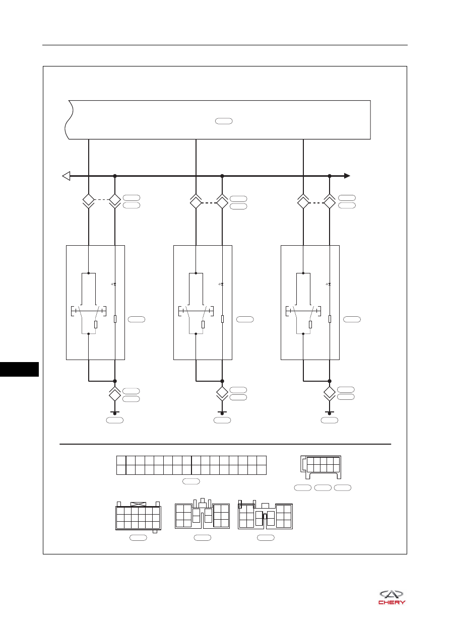
Power Window Control System (Page 3 of 3)

ET21430030

FRONT 
RIGHT 
POWER 
WINDOW 
SWITCH

BCM

3

9

1

6

GrR

BG

B13

12

Lg

Lg

17

UP

DOWN

220

B

B

B

3

3

9

1

6

WV

WV

B14

6

Lg

Lg

11

UP

DOWN

220

B

B

B

5

3

9

1

6

G

G

B15

Lg

Lg

UP

DOWN

220

B

B

B

5

B1 B2 B3 B4 B5 B6 B7 B8 B9 B10 B11 B12 B13 B14 B15 B16

B17 B18 B19 B20 B21 B22 B23 B24 B25 B26 B27 B28 B29 B30 B31 B32

A

ILLUMINATION

1 2 3 4

5

6 7 8 9 10

B-047

L

B-047

1

4

7 10 13 16

2

5

8 11 14 17

3

6

9 12 15 18

1

2

7

8

13

14

3

4

9

10

5

6

11

12

15

16

1

2

7

13

14

8

3

9

4

10

11

12

15

16

5

6

W

B-061

Y

B-026

Y

B-005

B-061

H-002

B-061

B-062

B-062

B-036

H-002

H-003

REAR 
LEFT 
POWER 
WINDOW 
SWITCH

L-002

REAR 
RIGHT 
POWER 
WINDOW 
SWITCH

R-003

B-026

L-005

B-026

L-005

B-005

R-002

B-005

R-002

6

11

B

H-003

B

L-002

B

R-003

43–

13

43

DIAGNOSIS & TESTING

Problem Symptoms Table

HINT:
Use the table below to help determine the cause of the problem. Check each suspected area in order. Repair 
or replace the faulty components, or adjust as necessary.

Diagnosis Tools

X-431 3G Diagnostic Tester

When connecting X-431 3G diagnostic tester:
 Connect X-431 3G diagnostic tester (the latest software) to Data Link Connector (DLC) for communication 

with vehicle.

 DLC is located at the driver side instrument panel crossmember.
 DLC uses a trapezoidal design which can hold 16 terminals.

Digital Multimeter

When using digital multimeter:
 Troubleshoot electrical malfunctions and wire harness system.
 Look for basic fault.
 Measure voltage, current and resistance.

DTC Confirmation Procedure

Confirm that battery voltage is normal before performing the following procedures.
 Turn ignition switch to LOCK.
 Connect X-431 3G diagnostic tester (the latest software) to Data Link Connector (DLC), and make it 

communicate with vehicle electronic module by the data network.

 Turn ignition switch to ON.

Symptom

Suspected Area

See page

Driver side power window cannot be 
operated with driver side power glass 
regulating control switch

Fuse

51-37

Driver side power glass regulating control 
switch

43-44

Driver side power glass regulator assembly

43-53

Wire harness or connector

-

Body Control Module (BCM)

-

Passenger side power window cannot be 
operated with passenger side power glass 
regulating switch

Fuse

51-37

Passenger side power glass regulating 
switch

43-55

Passenger side power glass regulator 
assembly

43-62

Wire harness or connector

-

Body Control Module (BCM)

-

Power window has intermittent problem

Ground

-

Wire harness or connector

-

43–

14

43

 Using X-431 3G diagnostic tester to record and clear the DTCs stored in the Body Control Module (BCM).
 Turn ignition switch to LOCK and wait for a few seconds.
 Turn ignition switch to ON, and then select "Read Code".
 If DTC is detected, the malfunction indicated by the DTC is current. Go to the diagnosis procedure - Step 1.
 If DTC is not detected, the malfunction indicated by the DTC is intermittent. Please refer to Intermittent 

DTC Troubleshooting.

Intermittent DTC Troubleshooting

If malfunction is intermittent, perform the followings:
 Check if connectors are loose.
 Check if wire harnesses are worn, pierced, pinched or partially broken.
 Wiggle related wire harnesses and connectors and observe if signal is interrupted in the related circuit.
 If possible, try to duplicate the conditions under which the DTC was set.
 Look for the data that has changed or the DTC to be reset during the wiggle test.
 Look for broken, bent, protruded or corroded terminals.
 Inspect the mounting areas of power window assembly, wire harness or wire harness connector and so on 

for damage, foreign matter, etc. that will cause incorrect signals.

 Check and clean all wire harness connectors and grounding parts related to the current DTC.
 Remove the Body Control Module (BCM) from the malfunctioning vehicle and install it to a new vehicle and 

perform a test. If DTC cannot be cleared, the Body Control Module (BCM) is malfunctioning. If DTC can be 
cleared, reinstall the Body Control Module (BCM) to original vehicle.

 If multiple trouble codes were set, refer to the circuit diagrams to look for any common ground circuit or 

power supply circuit applied to the DTC.

 Refer to Technical Bulletin that is applied to the malfunction.

Ground Inspection

Grounding are very important to entire circuit system, which are normal or not can seriously affect the entire 
circuit system. Ground points are often exposed to moisture, dirt and other corrosive environments. Corrosion 
(rust) and oxidation may increase load resistance. This situation will seriously affect the normal operation of 
the circuit. The operations to check the ground points are as follows:
1. Remove the ground bolt or nut.
2. Check all contact surfaces for tarnish, dirt and rust, etc.
3. Clean as necessary to ensure that contacting is in a good condition.
4. Reinstall the ground bolt or nut securely.
5. Check if add-on accessories interfere with the ground circuit.
6. If several wire harnesses are crimped into one ground terminal, check if they are installed correctly. Make 

sure all wire harnesses are clean, securely fastened and providing a good ground path.

43–

15

43

Diagnosis Procedure

HINT:
Use the following procedures to troubleshoot the power window control system.

Standard voltage: 11 to 14 V
If the voltage is below 11 V, recharge or replace the battery before proceeding to next step.

1

Vehicle brought to workshop

2

Check battery voltage

3

Customer problem analysis

4

Check for DTCs (current DTC and history DTC)

NEXT

NEXT

NEXT

For current DTC, go to step 6

For history DTC, go to step 7

DTC 
occurs

No 

DTC

5

Problem repair (no DTC), then go to step 8

6

Troubleshoot according to Diagnostic Trouble Code (DTC) chart, then go to step 8

7

Troubleshoot according to Problem Symptoms Table, then go to step 8

NEXT

NEXT

NEXT


Content   ..  456  457  458  459   ..