Chery Tiggo 5 (T21). Service manual - part 449
 

  Index      Chery     Chery Tiggo 5 (T21) - service and repair manual 2014 year


Search            copyright infringement  


Content   ..  447  448  449  450   ..


Chery Tiggo 5 (T21). Service manual - part 449


40–

7

40

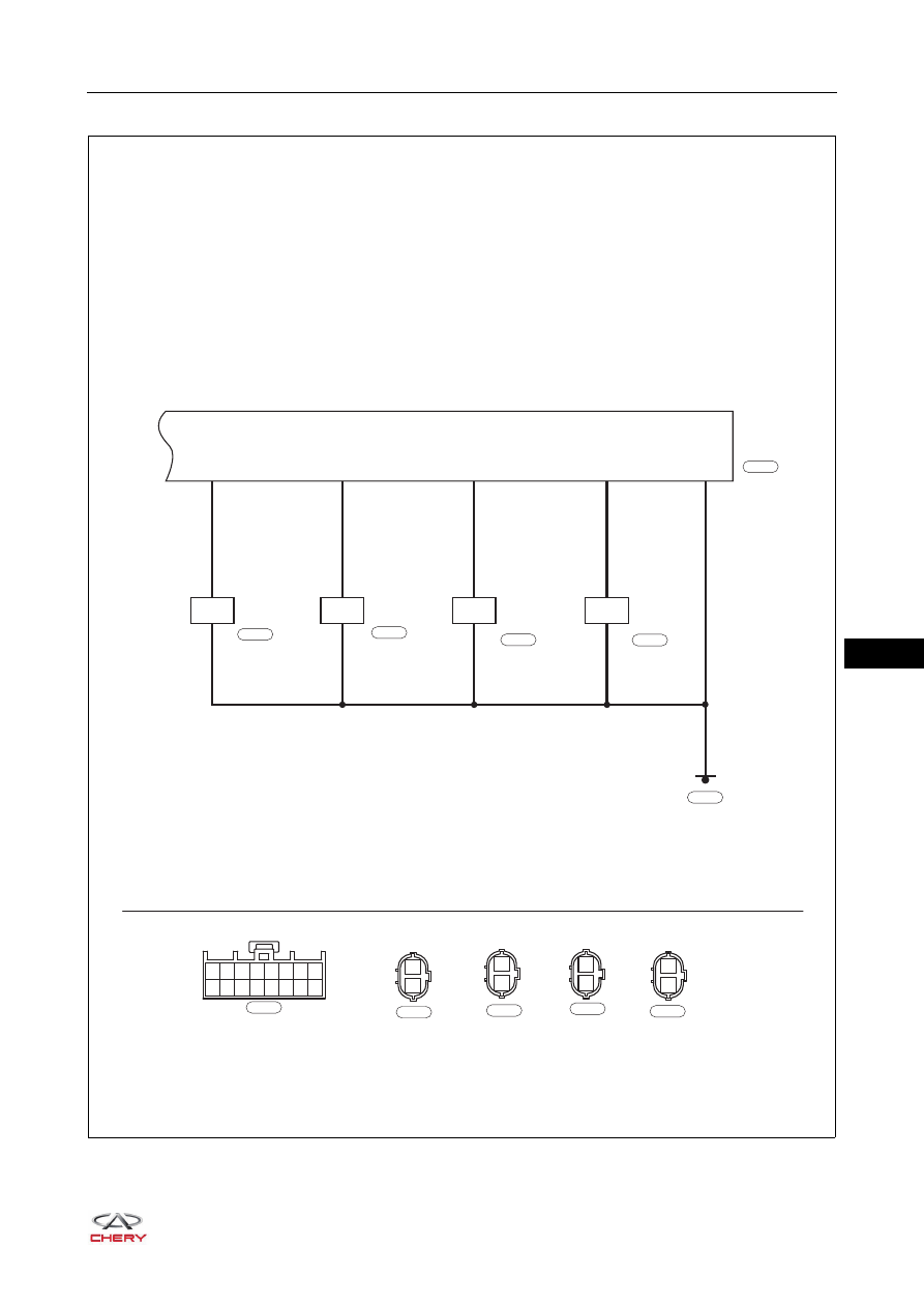
Reversing Radar System (Page 3 of 3)

ET21400030

REAR LEFT 
RADAR 
SENSOR

RW

WG

RB

B

B

B

B

B

LEFT 
CENTER 
RADAR 
SENSOR

7

1

2

8

15

16

1

2

RIGHT
CENTER
RADAR
SENSOR

1

2

GW

B

REAR RIGHT
RADAR
SENSOR

4

1

2

1

9 10 11 12 13 14 15 16

2

3

4

5

6

7

8

W

B-020

REVERSE
RADAR 
MODULE

B-020

2

1

2

1

2

1

2

1

B

B-023

B

B-027

B

B-030

B

B-033

B-023

B-027

B-030

B-025

B-033

40–

8

40

Reversing Radar Control Module Assembly Terminal List

Pin No.

Terminal Definition

Pin No.

Terminal Definition

1

Reversing Signal

9

-

2

-

10

-

3

Ignition Signal

11

-

4

Center Right Reversing Radar 
Sensor Signal

12

-

5

-

13

Data Signal (to Body Control Module 
(BCM))

6

-

14

-

7

Left Reversing Radar Sensor Signal

15

Right Reversing Radar Sensor 
Signal

8

Center Left Reversing Radar Sensor 
Signal

16

Ground

40–

9

40

DIAGNOSIS & TESTING

Problem Symptoms Table

HINT:
Use the table below to help determine the cause of problem symptoms. Check each suspected area in 
sequence. Repair or replace the faulty components, or adjust as necessary.

Self-checking Function

Reversing radar system has malfunction self-checking function, and the function instructions are as follows: 

If reversing radar sensor wire harness and connector are damaged or there is a malfunction in the reversing 
radar sensor body, the instrument cluster will alarm after turning ignition switch ON and shifting the shift lever 
to R.
Specific alarms are as follows:
1. When system is normal, the buzzer does not sound, and reversing radar system enters normal operation 

mode.

2. When there are malfunctions in one or more sensors, relevant reversing radar sensor malfunction will be 

displayed on multi-information display, other sensors can also enter normal operation mode.

Symptom

Suspected Area

See page

Reversing radar system does not function 
(buzzer in instrument cluster does not 
sound)

Back-up light switch Assembly

35-88

Reversing radar sensor

-

Camera

-

Reversing radar control module assembly

-

Instrument cluster

38-42

Wire harness and connector

-

40–

10

40

ON-VEHICLE SERVICE

Reversing Radar Sensor

Removal

1. Turn off all the electrical equipment and ignition switch.
2. Disconnect the negative battery cable.
3. Remove the rear bumper assembly (

See page 48-30

).

HINT:
The reversing radar sensor connector (arrow) has been 
disconnected when removing the rear bumper assembly.

4. Remove the reversing radar sensor.

a. Press the claws on reversing radar sensor.
b. Remove the reversing radar sensor from the rear 

bumper assembly.

CAUTION

 Be sure to wear necessary safety equipment to prevent accidents when removing the reversing radar 

sensor.

 Operate carefully to avoid damaging the reversing radar sensor when removing the reversing radar 

sensor.

RT21400060

RT21480422


Content   ..  447  448  449  450   ..