Chery Tiggo 5 (T21). Service manual - part 387
35–
23
35
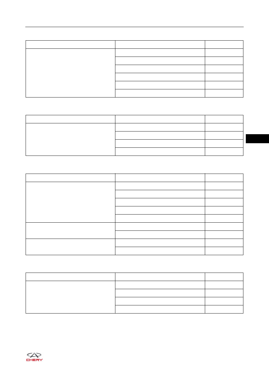
Front Fog Light
Rear Fog Light
Turn Signal Light and Hazard Warning Light
License Plate Light
Symptom
Suspected Area
See page
Front fog light does not come on
Fuse
Relay
Front fog light bulb
-
Headlight adjustment switch assembly
Wire harness or connector
-
Body Control Module (BCM)
-
Symptom
Suspected Area
See page
Rear fog light does not come on
Rear fog light bulb
-
Headlight adjustment switch assembly
Wire harness or connector
-
Body Control Module (BCM)
-
Symptom
Suspected Area
See page
Hazard warning light and turn signal light
do not come on
Bulb
-
Wire harness or connector
-
Hazard Warning Light Switch
Headlight adjustment switch assembly
Body Control Module (BCM)
-
Hazard warning light does not come on
(turn signal light is normal)
Hazard Warning Light Switch
Wire harness or connector
-
Turn signal light does not come on (hazard
warning light is normal)
Headlight adjustment switch assembly
Wire harness or connector
-
Symptom
Suspected Area
See page
License plate light does not come on
License plate light bulb
-
Headlight adjustment switch assembly
Wire harness or connector
-
Body Control Module (BCM)
-