Chery Tiggo 5 (T21). Service manual - part 359


  Index      Chery     Chery Tiggo 5 (T21) - service and repair manual 2014 year


Search            copyright infringement  


Content   ..  357  358  359  360   ..


Chery Tiggo 5 (T21). Service manual - part 359


32–

27

32

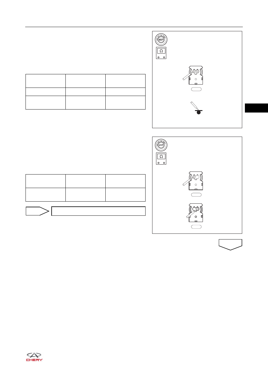
g. Turn ignition switch to LOCK, disconnect the negative 

battery cable and wait for at least 90 seconds. 

h. Using a digital multimeter, check for continuity between 

front passenger airbag connector I-028 and body ground 
to check for a short circuit to ground according to the 
table below.
Standard Condition

i. Release the activation prevention mechanism built into the 

SRS control module assembly connector  I-046/B-072.

j. Using a digital multimeter, check for continuity between 

the terminals of front passenger airbag connector I-028 
according to the table below.
Standard Condition

-

+

RT21320210

1 2

I-028

Multimeter 

Connection

Condition

Specified 

Condition

I-028 (1) - Body 

Always

No continuity 

I-028 (2) - Body 

ground

Always

No continuity

-

+

RT21320220

1 2

I-028

1 2

I-028

Multimeter 

Connection

Condition

Specified 

Condition

I-028 (1) - 

I-028 (2)

Always

No continuity

Replace SRS control module assembly

OK

NG

32–

28

32

a. Turn ignition switch to LOCK, disconnect the negative 

battery cable and wait for at least 90 seconds. 

b. Disconnect body wire harness connector B-055 and SRS 

control module assembly connector B-072 (*2).

c. Using a digital multimeter, check for continuity between 

the terminals of connector B-055 and connector B-072 
according to the table below. 
Standard Condition

4

Check airbag wire harness and connector (SRS control module assembly - body wire 
harness connector)

-

+

RT21320221

1

2

3

4

5

6

7

8

9 10 11 12 13 14 15 16

B-055

32

31

30

29

28

16

15

14

13

12

11

10

9

8

7

6

5

4

3

2

1

27

26

25

24

23

22

21

20

19

18

17

B-072

Multimeter 

Connection

Condition

Specified 

Condition

B-055 (7) - 

B-072 (5)

Always

Continuity

B-055 (8) - 

B-072 (6)

Always

Continuity

Replace body wire harness and connector

NG

OK

32–

29

32

a. Turn ignition switch to LOCK, disconnect the negative 

battery cable and wait for at least 90 seconds. 

b. Disconnect the SRS control module assembly connector 

I-046/B-072 and front passenger airbag connector I-028.

c. Using a digital multimeter, check for continuity between 

the terminals of connector  I-046/B-072 and connector 

I-028 according to the table below.
Standard Condition

5

Check airbag wire harness and connector (SRS control module assembly - front passenger 
airbag)

-

+

RT21320230

1 2

I-028

32

31

30

29

28

16

15

14

13

12

11

10

9

8

7

6

5

4

3

2

1

27

26

25

24

23

22

21

20

19

18

17

I-046

B-072

Multimeter 

Connection

Condition

Specified 

Condition

 I-046/B-072 (5) - 

I-028 (1)

Always

Continuity

 I-046/B-072 (6) - 

I-028 (2)

Always

Continuity

 I-046/B-072 (6) - 

I-028 (1)

Always

Continuity

 I-046/B-072 (5) - 

I-028 (2)

Always

Continuity

 I-046/B-072 (5) - 

 I-046/B-072 (6)

Always

Continuity

I-028 (1) - 

I-028 (2)

Always

Continuity

32–

30

32

d. Release the activation prevention mechanism built into the 

SRS control module assembly connector  I-046/B-072.

e. Using a digital multimeter, check for continuity between 

the terminals of connector  I-046/B-072 and connector 

I-028 according to the table below.
Standard Condition

-

+

RT21320230

1 2

I-028

32

31

30

29

28

16

15

14

13

12

11

10

9

8

7

6

5

4

3

2

1

27

26

25

24

23

22

21

20

19

18

17

I-046

B-072

Multimeter 

Connection

Condition

Specified 

Condition

 I-046/B-072 (5) - 

I-028 (1)

Always

Continuity

 I-046/B-072 (6) - 

I-028 (2)

Always

Continuity

 I-046/B-072 (6) - 

I-028 (1)

Always

No continuity

 I-046/B-072 (5) - 

I-028 (2)

Always

No continuity

 I-046/B-072 (5) - 

 I-046/B-072 (6)

Always

No continuity

I-028 (1) - 

I-028 (2)

Always

No continuity

Replace instrument panel wire harness 
and connector

NG


Content   ..  357  358  359  360   ..