Chery Tiggo 5 (T21). Service manual - part 261


  Index      Chery     Chery Tiggo 5 (T21) - service and repair manual 2014 year


Search            copyright infringement  


Content   ..  259  260  261  262   ..


Chery Tiggo 5 (T21). Service manual - part 261


23–

39

23

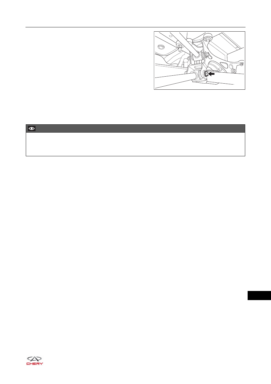
d. Remove the coupling bolt and nut (arrow) between 

upper part of rear suspension upper left swing arm 
assembly and rear sub frame assembly.

(Tightening torque: 120 ± 10 N·m)

e. Remove the rear suspension lower left swing arm assembly.

Installation

Installation is in the reverse order of removal.

RT21220340

CAUTION

 Always tighten coupling bolts and nuts to the specified torque.
 Check and adjust wheel alignment after installation.

23–

40

23

Rear Trailing Arm Assembly

Removal

HINT:

 Use the same procedures for the right side and left side.

 Procedures listed below are for the left side.
1. Remove the rear left wheel (

See page 24-9

).

2. Remove the rear left brake caliper assembly (

See page 26-41

).

3. Remove the rear left brake disc (

See page 26-41

).

4. Remove the rear left axle hub bearing unit (

See page 22-19

).

5. Remove the rear left trailing arm assembly.

a. Remove 2 coupling bolts (arrow) between rear left 

shock absorber assembly fixing bracket and rear left 
trailing arm assembly.

(Tightening torque: 80 ± 8 N·m)

b. Remove the coupling bolt and nut (arrow) between 

lower part of rear suspension lower left swing arm 
assembly and rear left trailing arm assembly.

(Tightening torque: 120 ± 10 N·m)

CAUTION

 Be sure to wear necessary safety equipment to prevent accidents.
 Make sure that safety lock of lifter has been locked when removing and installing chassis parts.
 It is not permitted to weld or modify suspension bearing parts.
 When removing and installing chassis parts, replace self-locking nuts and rusted nuts for safety.

RT21230380

RT21230390

23–

41

23

c. Remove the coupling bolt and nut (arrow) between 

lower part of rear suspension upper left swing arm 
assembly and rear left trailing arm assembly.

(Tightening torque: 120 ± 10 N·m)

d. Remove 2 coupling bolts (arrow) between rear left 

wheel speed sensor fixing bracket and rear left trailing 
arm assembly.

(Tightening torque: 23 ± 2 N·m)

e. Remove the coupling bolt (arrow) between parking 

brake cable fixing bracket and rear left trailing arm 
assembly.

(Tightening torque: 23 ± 2 N·m)

f. Remove the coupling bolt (arrow) between rear left 

brake line fixing bracket and rear left trailing arm 
assembly.

(Tightening torque: 23 ± 2 N·m)

RT21230400

RT21230440

RT21230450

RT21230460

23–

42

23

g. Remove the coupling bolt and nut (arrow) between 

front part of rear left trailing arm assembly and 
mounting bracket.

(Tightening torque: 120 ± 10 N·m)

h. Remove the rear left trailing arm assembly.

Installation

Installation is in the reverse order of removal.

RT21230470

CAUTION

 Always tighten coupling bolts and nuts to the specified torque.
 Check and adjust wheel alignment after installation.


Content   ..  259  260  261  262   ..