Chery Tiggo 5 (T21). Service manual - part 251


  Index      Chery     Chery Tiggo 5 (T21) - service and repair manual 2014 year


Search            copyright infringement  


Content   ..  249  250  251  252   ..


Chery Tiggo 5 (T21). Service manual - part 251


22–

20

22

Rear Sub Frame Assembly

Removal

1. Remove the rear wheel (

See page 24-9

).

2. Remove the center exhaust pipe assembly (

See page 11-15

).

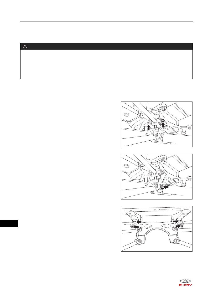
3. Remove the rear sub frame assembly.

a. Remove the coupling bolts and nuts (arrow) between 

rear suspension upper left swing arm assembly and 
rear sub frame assembly. Use the same procedure to 
remove the right side. 

(Tightening torque: 120 ± 10 N·m)

b. Remove the coupling bolt and nut (arrow) between 

rear suspension lower left swing arm assembly and 
rear sub frame assembly. Use the same procedure to 
remove the right side. 

(Tightening torque: 120 ± 10 N·m)

c. Remove 2 coupling bolts and 2 coupling nuts (arrow) 

between rear sub frame assembly and body.

(Tightening torque: 120 ± 10 N·m)

d. Remove the rear sub frame assembly.

WARNING

 Be sure to wear necessary safety equipment to prevent accidents. 
 Check if safety lock of lifter is locked when repairing chassis parts.
 It is not permitted to weld or modify bearing parts of wheel suspension and guide parts of wheel.
 When removing chassis parts, replace the self-locking nuts and rusted nuts for safety.

RT21220330

RT21220340

RT21220350

22–

21

22

Installation

Installation is in the reverse order of removal.

CAUTION

 Always tighten the coupling bolts and nuts to the specified torque.
 Check and adjust the rear wheel alignment after installation.

22–

22

1

23

SUSPENSION

GENERAL INFORMATION 

23-3

Description 23-3
Specifications 23-6
Tools 23-9

DIAGNOSIS & TESTING 

23-10

Problem Symptoms Table 

23-10

ON-VEHICLE SERVICE 

23-12

Front Shock Absorber Assembly 

23-12

On-vehicle Inspection 

23-13

Removal 23-13
Disassembly 23-15
Inspection 23-18
Assembly 23-18
Installation 23-18
Disposal 23-19

Front Control Arm Assembly 

23-20

Removal 23-20
Installation 23-21

Front Control Arm Ball Pin Assembly  23-22

Removal 23-22
Inspection 23-23
Installation 23-23

Front Stabilizer Bar Assembly 

23-24

Removal 23-24
Inspection 23-26
Installation 23-26

Front Stabilizer Link Assembly 

23-27

Removal 23-27
Inspection 23-27
Installation 23-28

Rear Shock Absorber Assembly 

23-29

Removal 23-30
Inspection 23-32
Installation 23-32
Disposal 23-33

Rear Coil Spring 

23-34

Removal 23-34
Inspection 23-36
Installation 23-36

Rear Suspension Upper Swing 

Arm Assembly 

23-37

Removal 23-37
Installation 23-37

Rear Suspension Lower Swing 

Arm Assembly 

23-38

Removal 23-38
Installation 23-39

Rear Trailing Arm Assembly 

23-40

Removal 23-40
Installation 23-42

Rear Stabilizer Bar Assembly 

23-43

Removal 23-43
Inspection 23-44
Installation 23-44

Rear Stabilizer Link Assembly 

23-45

Removal 23-45
Inspection 23-45
Installation 23-46

WHEEL ALIGNMENT 

23-47

Description 23-47
Specifications 23-47
Problem Symptoms Table 

23-48

Inspection before Wheel Alignment 

23-48

Front Wheel Toe-in 

23-49

Inspection 23-49
Adjustment 23-50

Front Wheel Camber, Kingpin 

Caster & Kingpin Inclination 

23-51

Rear Wheel Camber 

23-52

Adjustment 23-52

Rear Wheel Toe-in 

23-53

Adjustment 23-53


Content   ..  249  250  251  252   ..