Chery Tiggo 5 (T21). Service manual - part 231


  Index      Chery     Chery Tiggo 5 (T21) - service and repair manual 2014 year


Search            copyright infringement  


Content   ..  229  230  231  232   ..


Chery Tiggo 5 (T21). Service manual - part 231


18–

113

18

Transmission Fluid Cooler

Removal

1. Drain the coolant (

See page 12-13

).

2. Remove the engine lower protector assembly (

See page 48-29

).

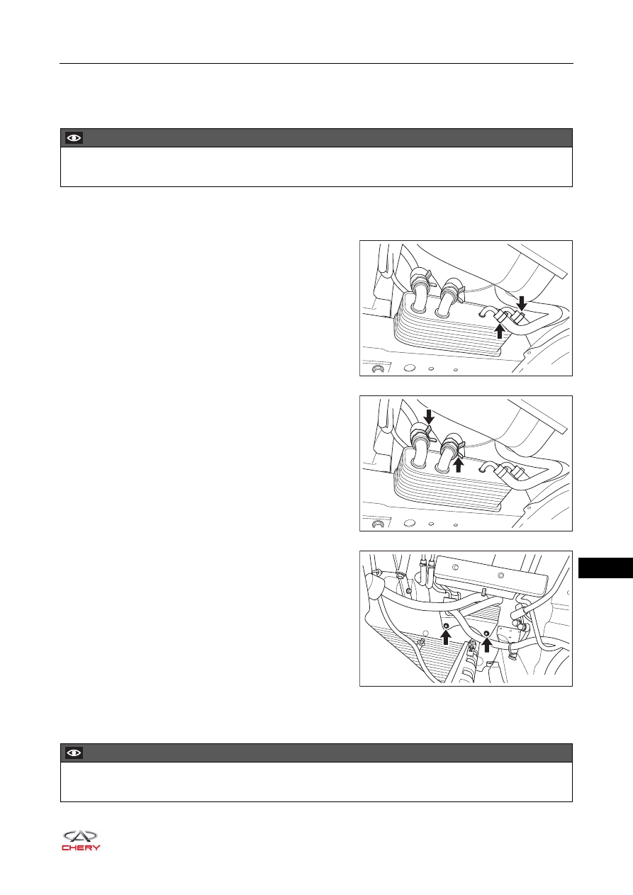
3. Remove the clamps and disconnect the cooling water 

pipes.

4. Remove the clamps and disconnect the transmission 

fluid pipes.

HINT:
Use appropriate tools to plug the transmission fluid pipes 
after removing them to prevent transmission fluid 
leakage.

5. Remove the transmission fluid cooler fixing bolts and 

remove the transmission fluid cooler.

(Tightening torque: 22 - 28 N·m)

Installation

Installation is in the reverse order of removal. 

CAUTION

 Do not perform the following removal process with the engine running to avoid causing serious injury.

RT21180340

RT21180350

RT21180360

CAUTION

 Check if transmission fluid is in the normal position. If not, add transmission fluid.

18–

114

18

Primary Shaft Speed Sensor 

Removal

1. Turn off all the electrical devices and ignition switch.
2. Disconnect the negative battery cable.
3. Remove the battery, battery tray and tray bracket (

See page 16-7

).

4. Remove the air filter (

See page 10-17

).

5. Disconnect the primary shaft speed sensor wire harness connector.
6. Remove the fixing bolt (1) of the primary shaft speed 

sensor and take out the primary shaft speed sensor (2). 

(Tightening torque: 10 - 12 N·m)

Installation

Installation is in the reverse order of removal.

2

1

RT21180370

CAUTION

 Keep clean of sensor and contact surface between sensor and transmission, and avoid dust or impurity 

entering the transmission.

 During installation, apply automatic transmission fluid on the O ring of the sensor. 

18–

115

18

Secondary Shaft Speed Sensor

Removal

1. Turn off all the electrical devices and ignition switch.
2. Disconnect the negative battery cable.
3. Remove the air filter (

See page 10-17

).

4. Disconnect the secondary shaft speed sensor wire 

harness connector (arrow).

5. Remove the fixing bolt (1) of the secondary shaft speed 

sensor and take out the secondary shaft speed sensor 
(2).

(Tightening torque: 10 - 12 N·m)

Installation

Installation is in the reverse order of removal.

1

2

RT21180380

CAUTION

 Keep clean of sensor and contact surface between sensor and transmission, and avoid dust or impurity 

entering the transmission.

 During installation, apply automatic transmission fluid on the O ring of the sensor.

18–

116

18

Turbine Speed Sensor

Removal

1. Turn off all the electrical devices and ignition switch.
2. Disconnect the negative battery cable.
3. Remove the battery, battery tray and tray bracket (

See page 16-7

).

4. Remove the air filter (

See page 10-17

).

5. Disconnect the turbine speed sensor wire harness 

connector (arrow).

6. Remove the fixing bolt (2) of the turbine speed sensor 

and take out the turbine speed sensor (1). 

(Tightening torque: 10 - 12 N·m)

Installation

Installation is in the reverse order of removal.

1

2

RT21180390

CAUTION

 Keep clean of sensor and contact surface between sensor and transmission, and avoid dust or impurity 

entering the transmission.

 During installation, apply automatic transmission fluid on the O ring of the sensor.


Content   ..  229  230  231  232   ..