Chery Tiggo 5 (T21). Service manual - part 216
18–
53
18
DTC Confirmation Procedure:
Confirm that battery voltage is between 11 and 14 V before performing the following procedures.
Turn ignition switch to LOCK.
Connect X-431 3G diagnostic tester (the latest software) to Data Link Connector (DLC), and make it
communicate with vehicle electronic module by the data network.
Turn ignition switch to ON.
Using X-431 3G diagnostic tester to record and clear the DTCs stored in the TCU.
Turn ignition switch to LOCK and wait for a few seconds.
Turn ignition switch to ON, and then select "Read Code".
If DTC is detected, the malfunction indicated by the DTC is current. Go to the diagnosis procedure - Step 1.
If DTC is not detected, the malfunction indicated by the DTC is intermittent. Please refer to Intermittent
DTC Troubleshooting.
Diagnosis Procedure
HINT:
After the fault is eliminated, verify DTC and symptom again.
a. Turn ignition switch to LOCK.
b. Disconnect the secondary speed sensor connector.
c. Check if the secondary speed sensor connector is dirty, oxidized, loose or damaged.
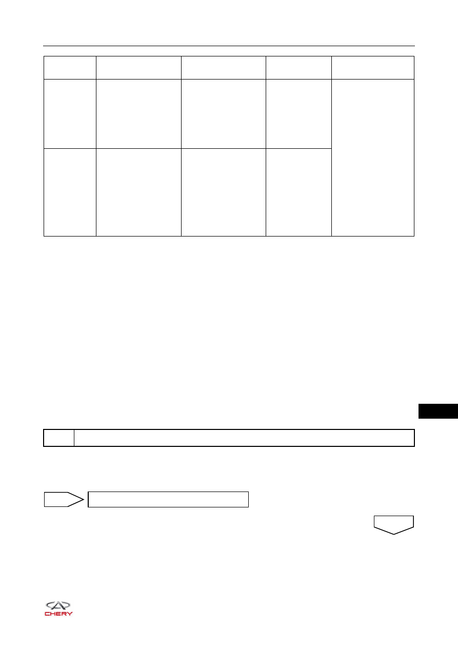
DTC Code
DTC Definition
DTC Detection
Condition
DTC Set
Condition
Possible Cause
P0720
Output Speed Sensor
Circuit
Start engine and keep
it at following status for
at least 1 min: throttle
opening not less than
10%, at D gear, engine
speed higher than 800
rpm
Output speed
signal is higher
than the
allowable value
within a period
Incorrect
installation of the
output speed
sensor
Signal circuit open
or short circuit
Output speed
sensor power
circuit poor contact
Output speed
sensor failure
TCU signal circuit
failure
P1745
Second Speed Sensor
Plausible
Start engine and keep
it at following status for
at least 30 seconds:
throttle opening higher
than 10%, at D gear,
vehicle speed higher
than 10 km/h
Difference
between output
speed after
conversing
vehicle speed
signal and actual
measured speed
is higher than
limit
1
Check wire harness connector
Repair fault
NG
OK