Chery Tiggo 5 (T21). Service manual - part 113


  Index      Chery     Chery Tiggo 5 (T21) - service and repair manual 2014 year


Search            copyright infringement  


Content   ..  111  112  113  114   ..


Chery Tiggo 5 (T21). Service manual - part 113


07–

38

07

Installation

1. Install the camshaft oil seal.

HINT:

 Use the same installation procedures for the exhaust camshaft oil seal and intake camshaft oil seal.

 Procedures listed below are for intake camshaft oil seal. 
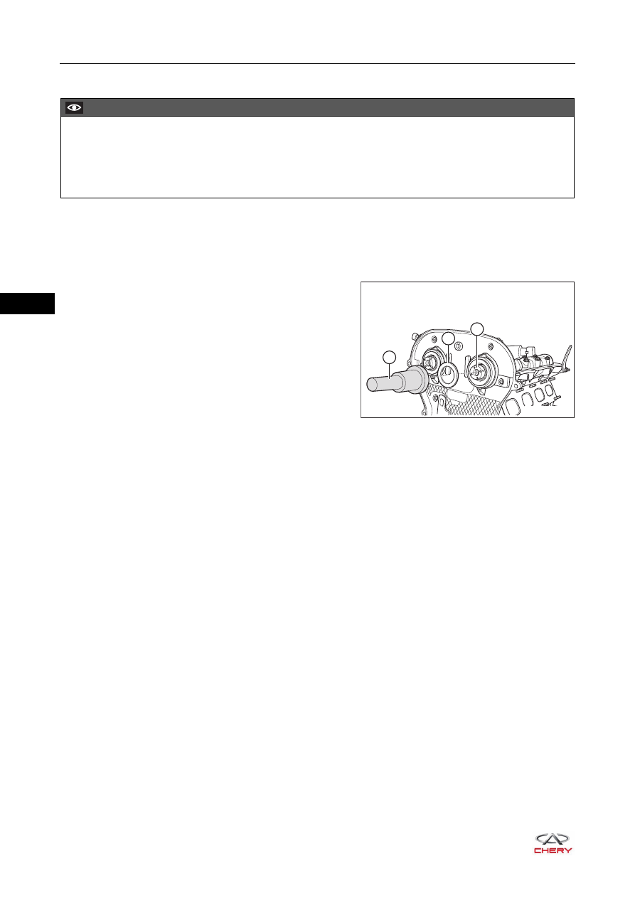
a. Using a special tool (camshaft oil seal installer) (1), 

install the intake camshaft oil seal (2) to intake 
camshaft (3).

2. Other installation procedures are in the reverse order of removal.

CAUTION

 Remove the dirt on oil seal retainer and apply a coat of engine oil to the oil seal retainer and oil seal lip 

before installation. 

 Be sure to prevent the lip of camshaft oil seal from being scratched during installation. If it is damaged, 

replace immediately.

RT21070240

1

2

3

07–

39

07

Crankshaft Front Oil Seal

Removal

1. Turn off all the electrical equipment and ignition switch.
2. Disconnect the negative battery cable.
3. Remove the engine trim cover assembly (

See page 10-10

).

4. Remove the engine lower right protector assembly (

See page 48-29

).

5. Remove the accessory drive belt (

See page 07-24

).

6. Remove the belt tensioner assembly (

See page 07-27

).

7. Use an engine equalizer to hang the engine right lifting eye. 
8. Remove the engine right mounting (

See page 07-68

).

9. Remove the engine timing belt (

See page 07-28

).

10.Remove the crankshaft timing pulley. 

a. Loosen the crankshaft timing pulley fixing bolt (arrow).

(Tightening torque: 1st step: tighten to 130 ± 10 N·m; 
2nd step: retighten by 65° ±  5°)

HINT:
Shift the transmission into 5th gear (for MT model) or 
D position (for CVT model) when loosening the 
crankshaft timing gear fixing bolt to engage the 
crankshaft and propeller shaft. Another technician 
depresses the brake pedal, which can lock the 
crankshaft by mechanical gear train. 

b. Remove the timing pulley fixing bolt (1), washer (2), 

crankshaft timing pulley (3), lining (4) and semi-circle 
key (5) in order.

CAUTION

 Be sure to wear necessary safety equipment to prevent accidents when repairing.
 Try to prevent body paint surface from being scratched during removal and installation. 

RT21070250

RT21070260

4

1

5

3

2

CAUTION

 Semi-circle key is small, so it is easy to be ignored. During installation, pay thorough attention not to 

forget to install. 

07–

40

07

11.Remove the crankshaft front oil seal.

a. Using a flat tip screwdriver wrapped with tape, pry out 

the crankshaft front oil seal (1) carefully.

Installation

1. Remove the dirt around the crankshaft front oil seal 

retainer and on its inner wall.

2. Install the crankshaft front oil seal guide tool (3) to the 

crankshaft (4).

3. Install the new oil seal (2) to the crankshaft front oil seal 

guide tool, and install the new oil seal to the oil seal 
retainer completely with a crankshaft front oil seal 
installer (1).

4. Install the lining (4).
5. Using a brass bar, install the semi-circle key (5) in place.

HINT:
Protrusion height of semi-circle key should be 2.2 - 2.3 
mm.

6. Install the crankshaft timing pulley (3), washer (2) and 

bolt (1) in order.

RT21070270

1

CAUTION

 Be careful not to damage the oil seal retainer and surface of crankshaft when removing crankshaft front 

oil seal.

CAUTION

 Apply a coat of engine oil to crankshaft front oil seal guide tool before installing the new oil seal. 
 Remove the dirt on oil seal retainer and apply a coat of engine oil to oil seal retainer and oil seal lip 

before installation. 

 Be sure to prevent the lip of crankshaft front oil seal from being scratched during installation. If it is 

damaged, replace immediately.

RT21070280

1

2

3

4

RT21070260

4

1

5

3

2

07–

41

07

7. Tighten the crankshaft timing pulley fixing bolt (arrow).

(Tightening torque: 1st step: tighten to 130 ± 10 N·m; 2nd 
step: retighten by 65° ± 5°)

8. Other installation procedures are in the reverse order of removal.

RT21070250


Content   ..  111  112  113  114   ..