Chery Tiggo 5 (T21). Service manual - part 75
06–
142
06
a. Unplug ECM fuse EF19 (10 A) from engine compartment fuse and relay box.
b. Check resistance of fuse EF19.
Standard resistance: less than 1 Ω
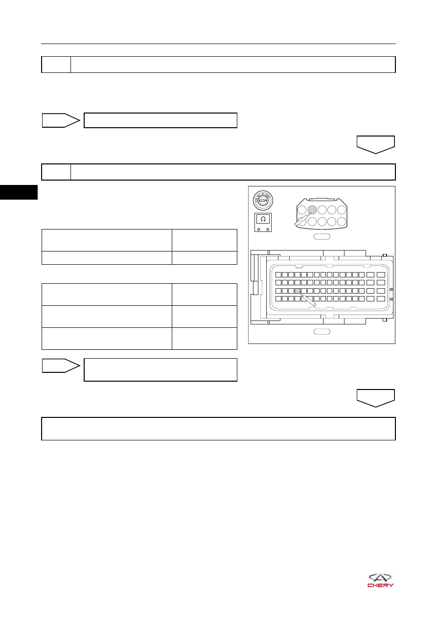
a. Disconnect engine compartment fuse and relay box
connector E-076.
b. Check wire harness between connector terminals.
Check for Open
Check for Short
6
Check ECM fuse
Replace ECM fuse
NG
7
Check wire harness and connector (ECM - engine compartment fuse and relay box)
OK
E-076
E-033
49 50 51
63
64
15
16
31
32
47
48
33 34 35
17 18 19
1 2 3
52 53 54 55 56 57 58 59 60 61 62
36 37 38 39 40 41 42 43 44 45 46
20 21 22 23 24 25 26 27 28 29 30
4 5 6 7 8 9 10 11 12 13 14
A1
A2
A3
A4
A5
A6
A7
A8 A9 A10
-
+
RT21065053
Multimeter Connection
Specified
Condition
E-033 (20) - E-076 (A2)
Continuity
Multimeter Connection
Specified
Condition
E-033 (20) or E-076 (A2) -
Body ground
No continuity
E-033 (20) or E-076 (A2) -
Battery positive
No continuity
Repair or replace wire harness or
connector
NG
Repair or replace engine compartment fuse and relay box or wire harness (engine compartment fuse
and relay box - battery)
OK