Lotus Evora. Instruction - part 50


  Index      Lotus     Lotus Evora - service repair instruction 2009 year


Search            


Content   ..  48  49  50  51   ..


Lotus Evora. Instruction - part 50


Lotus Service Notes   


    Section JL

Pressure Reduction

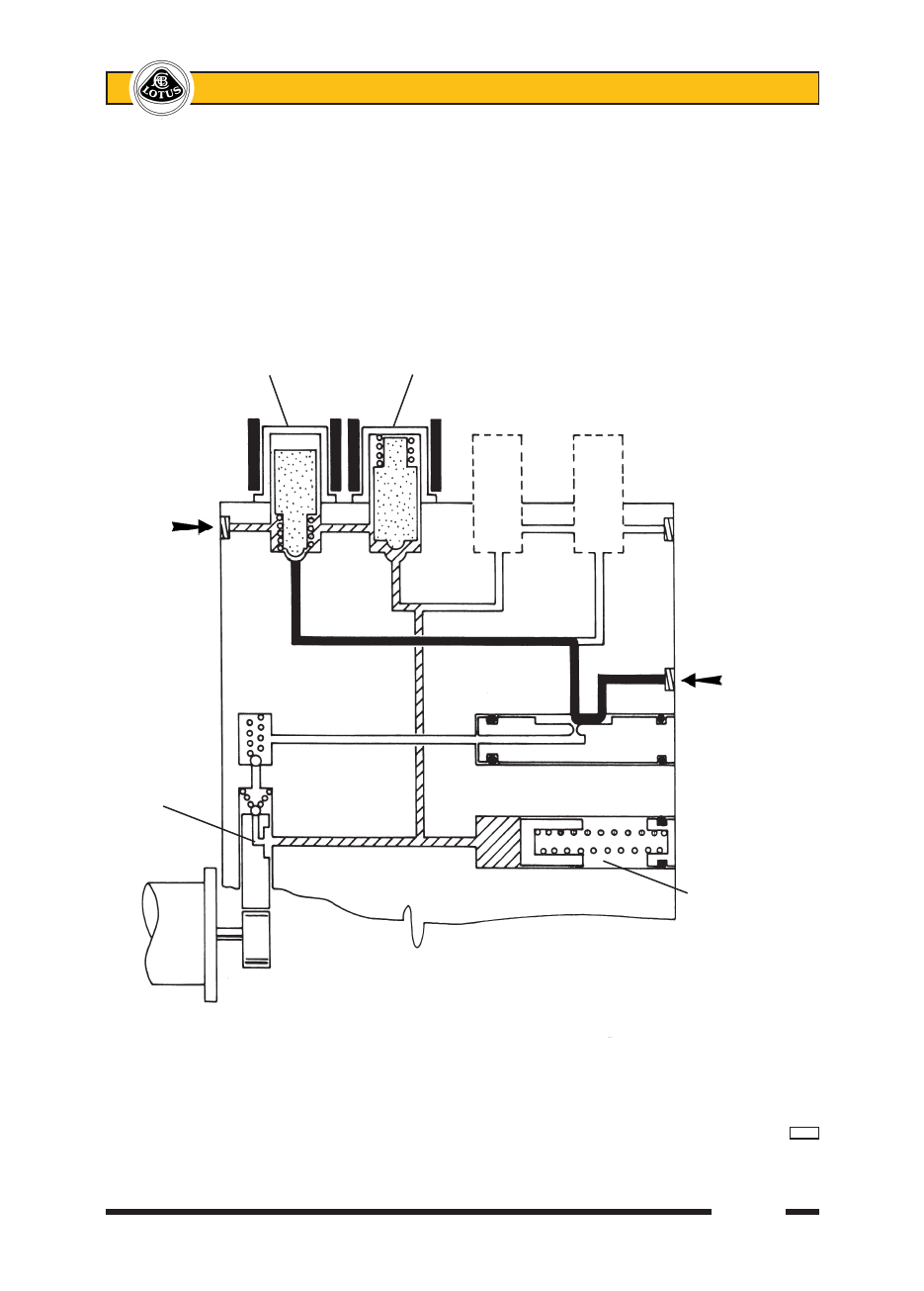
Once the LH front wheel brake circuit has been isolated from the master cylinder, the pressure must be 

reduced in order to allow wheel speed to be restored.  This pressure reduction is achieved by the ECM energis-

ing the dump valve solenoid, which then opens against spring pressure and bleeds off some of the fluid into the 

low pressure accumulator shared with the RH front circuit.  Very short activation pulses are used to maintain 

close control of the pressure reduction, and to limit the reduction to that required to restore wheel speed.  Fluid 

displaced from the wheel brake circuit is stored in the front brake accumulator against spring pressure, and is 

also used to prime the hydraulic pump.

        Isolation valve       Dump valve

        energised and        energised and 

        closed            open

Fluid 

bleeds 

off from 

LHF circuit

                                                            Inlet from

                                                            master

                                                            cylinder


Pump is 

primed

                                                        Low pressure

                                                        accumulator

                                                        charged


                                j149c


Lotus Service Notes   


    Section JL

Pressure Increase (Re-apply)

As soon as imminent wheel lock is detected by the ECM, and the ABS control system is activated, the 

pump motor is energised.  When the dump valve is opened, and fluid is allowed to bleed off from the wheel 

brake circuit into the low pressure accumulator, this fluid is scavenged by the pump and returned back into the 

input circuit through an attenuator orifice.  This action is the origin of the ‘pedal pushing back’ sensation felt by 

the driver, with the pressure pulsations from the pump damped and quietened by the restriction of the orifice.  

When wheel speed has been restored and the brake pressure is required to increase, the isolation valve is 

momentarily opened, to allow master cylinder/pump pressure to raise the pressure in the wheel brake circuit 

in increments.  If imminent locking is again sensed, the isolation valve closes, the dump valve opens and the 

cycle repeats, with the whole process occuring several times a second.  

          Isolation valve

          pulsed open

Increasing

pressure

to LHF

brake

                                                            Inlet from

                                                            master

                                                            cylinder


                                                            Attenuator

Pump                                                         orifice

operating


                                                        Accumulator

                                                        discharges into 

                                                        pump


                                j149d


Lotus Service Notes   


    Section JL

Brake Release

When no further wheel locking is sensed by the ECM, the ABS becomes inactive with the isolation valve 

open (solenoid de-energised) to allow direct communication between the master cylinder and wheel brake 

circuit, and the dump valve closed (solenoid de-energised) to seal off the pressure relief circuit.  The pump will 

remain running for a short time to help drain any fluid from the accumulator, whose piston is returned to its start 

position under the action of the spring, and return the fluid to the master cylinder reservoir.

          Isolation valve

          de-energised 

          and open

Output

to LHF

brake

                                                            Inlet from

                                                            master

                                                            cylinder

Pump runs

for short

period

                                        Fluid scavenged from

                                        low pressure accumulator


                   j149e


Lotus Service Notes   


    Section JL

JL.12 - ELECTRO-HYDRAULIC UNIT

The electro-hydraulic unit is located on the front side of the driver's toebox, and is accessible from below 

after removal of the front undertray.  The protective cover may be removed after slackening the two retaining 

nuts.  The unit is secured to the mounting bracket via two studs and a bottom spigot, all supported in flexible 

grommets.  The mounting bracket is fixed to the chassis by four bolts.  A single 38 pin connector plug with a 

cam lever is provided to connect the vehicle harness to the control module.

CAUTION: Do not disconnect or connect the main connector plug with the ignition switched on.  Switch 

off the ignition and disconnect the harness before carrying out any electrical welding operations on 

the car.

Hydraulic pipe connections to the unit comprise two input pipes from the master cylinder (one for the front 

circuit, one for the rear) and four output pipes, one for each of the wheel brakes.  Note that all hydraulic con-

nections are identified by engraved markings on the unit:

Input:

MC1     From master cylinder rear port (front brake circuit)

MC2     From master cylinder front port (rear brake circuit)

Output:

FL      Front left

FR      Front right

RR      Rear right

RL      Rear left

To Remove Electro-Hydraulic Unit

When removing the unit, beware of dripping brake fluid and take appropriate precautions to prevent dam-

age to paintwork.

1.  Raise the vehicle and remove the front undertray.  Remove the module protective cover.

2.  Switch off the ignition before pressing the release tab and folding back the cam lever to disconnect the 

harness plug.  

3.  Label each of the hydraulic pipes before disconnecting from the unit and immediately capping the pipes 

and plugging the ports to reduce the spillage of brake fluid, and to prevent the ingress of dirt.

4.  Release the four bolts securing the mounting bracket to the chassis and withdraw the bracket with ABS 

unit.

5.  To remove the unit from the bracket, release the two retaining nuts from the studs and slide the unit from 

its three grommets.

6.  To refit, reverse the removal procedure, taking care to connect the brake pipes correctly:


Mounting bracket to chassis;    24 Nm

Modulator inlet pipes;        18 Nm

Modulator outlet pipes;       16 Nm 

7.  Bleed the unit of air (see Sub-section JL.3).

8.  Verify correct connection by using the ‘Lotus Techcentre’ tool in actuator tests with the car on a wheel free 

lift.  Check that operation of each solenoid valve affects the appropriate wheel. 

Note that the ABS controller is calibrated specifically for the Evora.  Do not use parts from other 

sources.


Content   ..  48  49  50  51   ..