Lotus Elise / Lotus Exige. Instruction - part 114


  Index      Lotus     Lotus Elise / Lotus Exige (engine 1ZZ/2ZZ) - service repair instruction 2004 year


Search            


Content   ..  112  113  114  115   ..


Lotus Elise / Lotus Exige. Instruction - part 114


Page 5


Lotus Service Notes   


        2-Eleven

2-ELEVEN.A - CHASSIS

The 2-Eleven uses the basic chassis 'tub' of the Elise/Exige with minor revisions including;

Deletion of door hinge upright extrusions on each end of scuttle beam.

Full height side members (no cabin access cut down).

Revised pick up points for the roll over bar.

Addition of a body side attachment panel to the lower edge of each chassis rail sill extension.

The front crash structure is as Elise/Exige with minor fettling revisions, and the galvanised steel rear 

subframe differs only in respect of incidental fixings.

Roll-Over Bar

The  tubular  steel  roll-over  bar  is  substantially  cross-braced,  including  provision  for  shoulder  harness 

anchorage, and features integral bracing struts to both front and rear.  The feet of the main hoop are bolted to 

tapping plates riveted into the top surface of the chassis side rails, with the front bracing struts locating against 

the joint between the side rail top and scuttle cross-beam and secured by similar riveted tapping plates.  The 

rear bracing struts use a single fixing bolt at each side to secure to the rear subframe.

The roll-over bar complies with FIA requirements for international motorsport, but note that any additions 

or modifications to the 'bar may invalidate such compliance.
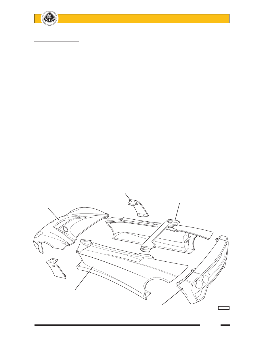
2-ELEVEN.B - BODY

On the 2-Eleven, the rear transom/bumper, body exterior side panels, ‘A’ panels, front splitter and splitter 

end support panels and the single panel comprising the whole of the nose section and front wings, are secured 

by threaded fasteners to permit easy removal for access to chassis or powertrain components, and allow simple 

and economic accident repair.  The composite body inner sides, together with the alloy sheet front and rear 

cabin bulkheads and rear scuttle panel, are secured with an elastomeric adhesive.  

Screw fixed body panels            'A' panel

                                            Rear scuttle panel (also bonded)

Front body section

            Body side

                                Rear transom/bumper                      

pl1001cc


Lotus Service Notes   


        2-Eleven

Page 6

All composite panels on the 2-Eleven are designed for light weight consistent with aerodynamic function, 

with some panels featuring core mat technology to provide a sandwich construction for enhanced stiffness.  

All panels are nevertheless vulnerable to damage caused by inappropriate subjection to  bodyweight or other 

misapplied forces.  

Note: The 2-Eleven is not equipped with conventional shock absorbing bumpers, so extra care should be taken 

when parking to guard against body damage.  The Lotus 2-Eleven does not offer the same kind and degree of 

impact resistance or energy absorption afforded by normal bumper systems.  Some panels, including the front 

quarter panels and ‘A’ panels, have sacrificial functions to help reduce repair costs and damage to the front 

body section in minor accidents.

Care is also required, due to the low ground clearance, to guard against chassis underside damage caused 

by ramps, kerbs and road humps.  Note that the front splitter panel is constructed from timber composite, 

sealed by a layer of resin, and that the occasional grounding of this panel, which is a normal occurrence under 

track conditions, will cause erosion of the outer layer, requiring periodic repair (water absorption may promote 

eventual de-lamination) or replacement.

Engine Lid

A removable panel in the rear body is secured by two recessed ‘Aerocatches’ and provides access to the 

engine for maintenance operations.

To remove the cover, at each latch, press the smaller section of the flush fitting latch plate to allow the 

latch plate lever to spring up.  Fully raise the lever to release the latch.  Lift the rear of the panel, and then draw 

rearwards to disengage the front flange from beneath the rear scuttle, before lifting the panel forwards and over 

the rear aerofoil.  Park the panel where it is unlikely to be damaged or blown away by wind.

To refit, rest the panel on the two rubber buffers at the front of the body aperture and slide forwards to 

engage the tang bracket at each side of the panel, beneath the body edge adjacent to the roll bar backstays, 

and the panel front flange beneath the rear scuttle edge.  Press down the two latch levers to engage the retain-

ing pins, finally pressing the small buttons to allow the lever ends to be captured.   Ensure that each lever is 

correctly clipped shut, and flush with the body surface.

Rear Transom/Bumper Panel

The rear transom panel is screw fixed in the following manner:

At each side, an angle bracket bonded to the underside of the transom top surface is secured by two 

screws to the aerofoil mounting strut. 

A row of screws secures the lower edge of the panel to the muffler alloy heatshield, which is itself screwed 

to the rear subframe.

Bonded Body Panels

                                          Body inner side panel

Front bulkhead


pl1002cc 


      Body inner side panel                                  Rear bulkhead

                                                      (also bonded to rear  

                                                      scuttle panel)      


Page 7


Lotus Service Notes   


        2-Eleven

At each side, two screws pass through the transom end flange into captive nuts in the body side panel.

Rear Scuttle Panel

The rear scuttle panel is fixed at each side by two horizontally disposed M6 screws into bond nuts on the 

body side panel, and is bonded along the top edge of the rear bulkhead.

Body Side Panel

The body side panels are secured by screw fasteners for ease of access and replacement.  Each panel 

is retained as follows:

The top edge of the body outer side panel lips over the body inner side panel, to which it is fixed with four 

screws engaging with captive nuts in the inner panel.

A single screw passes from beneath, through the end of the rear bulkhead capping rail into a captive nut 

in the side panel.

The lower edge of the body side is secured to four threaded inserts in a chassis extension flange.

At the front of the rear wheelarch, two screws secure the side panel baffle/stiffener to a vertical angle 

bracket bolted to the main chassis rail.

At the rear end of the panel, two screws pass from beneath, through the rear transom flange into captive 

nuts in the body side.

At the front of the body side, two screws pass upwards into captive nuts in the rear end of the front body 

panel.

'A' Panels

At the front of each body side, a separate 'A' panel is used to form a duct for air exhausting from the front 

wheelarch.  Each panel is secured by four screws at the top (2 into the body side, 2 into the front body panel), 

and 2 screws into the body side sill at the bottom.

Front Quarter Panels

A front quarter panel is fitted ahead of each front wheel and forms a mounting and duct for the oil cooler, 

as well as tying the front corner of the body to the splitter panel.  The quarter panel is fixed by:

2 screws from beneath, through the splitter into captive nuts in the quarter panel lower flange.

2 screws down through the front body flange into captive nuts in the quarter panel upper flange.

Front Wheelarch Shields

A small moulded plastic panel is fitted within each front wheelarch, fixed between the body side and radia-

tor mounting panel, and provides protection for the cooling and brake system components.

Front Undertray

An alloy sheet undertray is fitted beneath the nose, and stabilises the front body, splitter panel, and crash 

structure to the front of the chassis.  The undertray is secured by:

3 screws into the front edge of the chassis (also slots into the extrusion).

3 screws and nuts at each side into the lower flange of the crash structure.

5 fixings around the front edge, passing through the splitter into captive nuts in the front body flange.

2 screws and nuts to a central support bracket from the crash structure.

1 screw each side to the splitter panel.

Front Splitter Panel

A flat timber composite splitter panel is mounted beneath the nose to cleanly split the airflow above and 

below the underside of the car to optimise aerodynamic downforce whilst minimising drag.  A road and race 

version of the panel are designed to balance the forces produced by the two types of rear aerofoil.  Note that 

the front splitter panel is constructed from timber composite, sealed by a layer of resin, and that the occasional 

grounding of this panel, which is a normal occurrence under track conditions, will cause erosion of the outer 

layer, requiring periodic repair or replacement.

The panel is secured by:

Undertray fixings as listed above.

2 screws at each side to the front quarter panel.


Lotus Service Notes   


        2-Eleven

Page 8

Front Body Panel

To remove the front body panel for access to the radiator, front suspension, brake control system and other 

front chassis components, proceed as follows:

Release each of the two oil coolers from the front body by removing the two securing screws.

Remove the aero screen to prevent damage, or at least release the two rearmost fixings at each side 

securing the screen to the body sides.

Remove the single screw each side from within the front corner of the cockpit into a captive nut in the 

body.

Remove the two screws each side from within the 'A' panel duct into captive nuts in the body.

Remove the two screws each side fixing to the top of the front quarter panels.

Remove the single screw each side from beneath, fixing the splitter panel to the body inboard of the oil 

coolers.

From beneath the nose, remove the 5 screws securing the splitter panel to the body flange.

Carefully lift the front body from the car, disconnecting the wiring harness if applicable.

Note that the front turn lamps (if fitted) are bonded into the front body using Betaseal products. 

Rear Aerofoil

Two types of rear aerofoil are available.  For road going cars, a fixed angle GFRP composite curved blade 

with integral end plates is used, whereas the track optimised aerofoil is made using carbon fibre with alloy end 

plates, and has provision for adjusting the angle of incidence.  Each type should only be used with the corre-

sponding front splitter panel in order to maintain the correct aerodynamic balance.

Both aerofoil types are mounted via machined alloy support plates to the top surface of the rear subframe.  

Each plate uses an angle bracket at its base to secure to the subframe, and two of the same angle bracket to 

brace the plate to the rear clamshell through which the plate penetrates.  A further angle bracket secures the 

blade to the top of the support plate.

The  track  type  aerofoil  angle  of  attack 

may be adjusted by loosening the rear pivot 

screw on each support plinth, and removing 

the  front  fixing  screw.   Tilt  the  blade  to  the 

desired angle, and refit the screw in the most 

appropriate  fixing  hole.    Tighten  all  fixings 

securely.

Slots are also provided on the endplates 

to  allow  correct  horizontal  alignment  to  be 

maintained after adjustment of blade angle.

Exterior

The Launch Edition of the 2-Eleven is finished in a two tone combination of B111 Lotus Sport Black and 

B115 Arctic Silver, with yellow/black/silver styling decals.  A '2 Eleven' decal is applied to the rear transom panel, 

with optional larger decals on each body side.  Stone chip film is fitted to vulnerable areas.

Mirrors

A  central  rear  view  mirror  is  mounted 

on the top of the cabin front scuttle, with an 

additional mirror on both the driver's and pas-

senger's body sides.  Each of the convex glass 

mirrors may be adjusted after slackening (turn 

anticlockwise from above) the knurled clamp 

nut below the mirror.

            Tighten 

            to fix

                          Slacken

                          to adjust


ohs164B


                                Pivot screw

  Alternative

  fixing hole

  positions


ohs166


Content   ..  112  113  114  115   ..