Lotus Elise / Lotus Exige. Instruction - part 73


  Index      Lotus     Lotus Elise / Lotus Exige (engine 1ZZ/2ZZ) - service repair instruction 2004 year


Search            


Content   ..  71  72  73  74   ..


Lotus Elise / Lotus Exige. Instruction - part 73


Page 14


Lotus Service Notes   


    Section MP

Engine Compartment

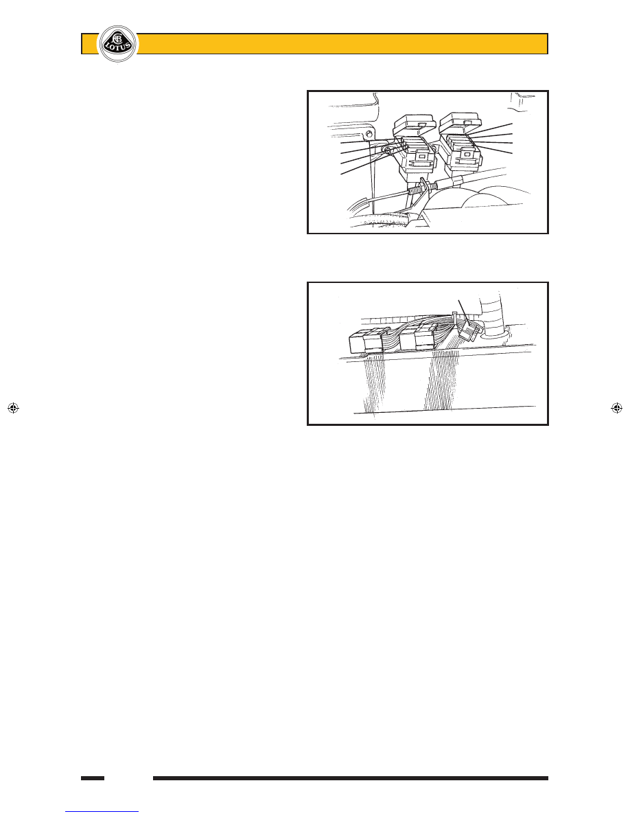
Fuses  and  relays  associated  with  the 

engine  management  system  are  contained 

in two 4-position fuse holders located at the 

front of the engine bay on the cabin bulkhead, 

adjacent to the engine ECM.  To access the 

fuses, unclip rear edge of the cover.

Fuse no.  Rating 

Circuit

R1    

20A   

Fuel pump

R2    

3A   

Immobiliser

R3    

5A   

Alternator sense

R4    

5A   

ECU battery feed

R5    

5A   

O2 heaters

R6    

7.5A  

VSV's VVT, VVL, IAC

R7    

10A   

Injectors, ignition coils

R8    

5A   

Re-circ. pump

Interior Fuses & Relays

The  wash/wipe  module,  turn/hazard 

flasher relay, horn relay and a relay for inertia 

switch activation of the central door locking, 

are mounted on the scuttle beam above the 

passenger footwell, with four fuses secured to 

the harness in that area.

Fuse no.  Rating 

Circuit

C1    

20A   

Interior fan

C2    

15A   

Wiper motor

C3    

7.5A  

Audio key-in

C4    

10A   

A.C. compressor

 A 60A Maxi fuse protecting the ABS circuit is located beneath the passenger side fascia top, adjacent to 

the positive post.

 A multi-function relay unit containing the engine control relay, fuel pump relay and starter relay is mounted 

in the engine bay near the ECU.  A similar relay unit is mounted in the front services compartment alongside 

the fusebox, and operates the a.c. compressor and radiator fans.

  Important Note:  Although the two modules 

are identical in appearance, their function is different and they must not be transposed.  The a.c. relay module 

A117M0038F has a brown label marked YWB100800;  The engine relay module A111E6024F has a white label 

marked YWB100970.

 For the location of the vehicle alarm system components, see sub-section MP.1.  

Fuse colours: 

2A - Black  

3A - Violet 

4A - Pink 

5A - Orange 

7.5A - Brown  10A - Red

15A - Light Blue 20A - Yellow 

25A - Clear

Relay Position

RHD: 

Inboard top;   

Wiper


Inboard bottom; 

Flasher


Outboard top; 

CDL trip


Outboard bottom; 

Horn

LHD:  

Inboard top;   

Flasher


Inboard bottom; 

Wiper


Outboard top; 

Horn


Outboard bottom;   CDL trip

              ENGINE BAY FUSES

                              8

                              7   

    4                          6

    3                          5

    2

    1


 ohs136


  Front            Fusebox ‘C’

  Viewed

  from 

  beneath


m248a


sn_mp_ cyclone.indd   14

02/01/2008   04:42:08

Page 15


Lotus Service Notes   


    Section MP

Component Location

MP.6 - AUDIO EQUIPMENT 

The Elise may be specified with various 

audio equipment options.  All cars are fitted 

with  a  main  wiring  harness  which  includes: 

an ISO 16-way connector located behind the 

standard ISO size audio aperture in the dash 

panel;  speaker  wiring  terminating  behind 

the cabin LH rear corner trim panel; and an 

analogue di-pole aerial routed inside the front 

body.  On cars factory built with a digital audio 

set, this aerial is supplemented by a digital di-

pole aerial routed in a similar manner.   

Speakers

'Two  speaker'  cars  are  fitted  with  a   

speaker in each cabin rear corner in a sound 

deadening full width rear bulkhead trim panel.  

An  upgraded  audio  option  uses  the  same 

rear  speakers,  in  conjunction  with  a  pair  of 

front  speakers,  mounted  one  in  each  dash 

end panel.  USA cars have the front speakers 

mounted in the fascia top panel.  

                                CDL module            Engine bay fuseboxes   


Horn mounted

on crash structure                              ECU                         

                                          mounting

                                          plate           

Fusebox


                                                              Inertia

                                                              switch


Radiator fan/a.c.                                                     

control module                                                           

                                                Fuse

                            ABS                  block                  

                            fuse

        Switch                                Horn relay              

pl1703mt

        controller                              CDL trip relay

                                             Flasher unit

                                             Wiper delay

                             Front speaker

                                Speaker

                                grille


     m243

sn_mp_ cyclone.indd   15

02/01/2008   04:42:09

Page 16


Lotus Service Notes   


    Section MP

Speaker specifications are as follows:

Rear: Blaupunkt GTX 542 2-way co-axial; 90W max; 30W RMS; 4 ohms impedance.

Front: Blaupunkt TSX 402 2-way co-axial; 105W max; 35W RMS; 4 ohms impedance.

To remove the rear bulkhead trim panel, remove the four screws securing the top edge of the panel to the 

bulkhead plinth, and ease the panel from behind the seat belt mounting frame at each side.

MP.7 - BATTERY, BATTERY CABLES & EARTHING POINTS

Battery

WARNING: POISON/DANGER - CAUSES SEVERE BURNS - KEEP OUT OF REACH OF CHILDREN.

Contains sulphuric acid - avoid contact with skin, eyes or clothing.  If in contact with skin or eyes; flush 

with copious amounts of water.  Remove contaminated clothing.  Seek immediate medical attention.  If 

ingested; seek immediate medical attention .  Do not induce vomiting or give fluids to drink.

Batteries produce explosive gases.  Keep sparks, flames and cigarettes away.  Ventilate when charging 

or using in enclosed space.  Always shield eyes when working near batteries.

Battery Access

The 45 Ahr Yuasa type 063/3 battery is located at the left hand front of the rear luggage compartment.  

No routine inspection or topping up of the electrolyte is required, but at intervals specified in the Maintenance 

Schedule, the battery terminals should be checked for security and condition, and protected with petroleum 

jelly.

To remove the battery, unhook the plastic cover, disconnect both battery cables (see below), and pull 

off the breather pipe (if applicable).  Release the single screw securing the clamp bracket at the rear base of 

the battery, and manoeuvre the battery from the base retaining shoes at the front and right hand side.  When 

lifting out the battery, be aware of the considerable weight, and take all appropriate precautions to safeguard 

personal health.

Refit the battery, with its terminals inboard, by reversing the above procedure.  Remember to push on the 

breather pipe (if applicable), and reconnect the battery cables as detailed below.

Disconnecting the Battery

If the battery is to be disconnected, the following precautions should be taken:

i) 

Wait for at least ten seconds after switching off the ignition to allow the engine management system to 

adjust the setting of some components ready for re-starting.

ii)  If the car is fitted with the upgraded security alarm, immediately before disconnection, mobilise the engine 

using the transmitter button with ignition off, and disconnect the battery within 25 seconds.  If disconnected 

after this time, or when immobilisation is in effect, the alarm will be triggered.

iii)  Ensure that all electrical loads (e.g. lights) are switched off.

iv)  Disconnect the negative (earth; black; ‘-’) battery cable first, and re-connect last.  If the battery positive 

terminal is inadvertently earthed (e.g. when using a spanner) whilst the negative terminal is still connected, 

the resultant short circuit with heavy sparking and current flow could cause serious burns.

v)  If the vehicle is fitted with security coded audio equipment,  check that the code is available for entering 

after battery reconnection.


Battery 

  clamp


ohs145

sn_mp_ cyclone.indd   16

02/01/2008   04:42:09

Page 17


Lotus Service Notes   


    Section MP

Battery Reconnection

i) 

Check again that all electrical loads are switched off.

ii) 

Connect the positive battery cable first, followed by the negative (earth) cable.

iii)  Be aware that the vehicle security alarm may be triggered by the action of battery re-connection.  Have 

the alarm transmitter key ready to disarm the alarm (see ‘Vehicle Security Alarm’). 

iv)  After reconnection, a change in the engine performance characteristics may be noted for a period whilst 

the computer controlled engine management system ‘re-learns’ some of its settings. 

v)  If necessary, enter the security code into audio equipment.

Battery Charging

Under conditions of normal daily use, it should not be necessary to use external battery charging equip-

ment.  In a low usage regime, however, it is important to maintain the charge state of the battery using a trickle 

charger, or an automatic battery management charger such as that available through Lotus After Sales.  Such 

devices, when connected to a vehicle battery, continuously monitor battery charge state and switch on and 

off automatically in order to maintain the battery in a fully charged state without danger of damage through 

overcharging.  

If the battery becomes discharged to the extent that the vehicle cannot be started, the recommended 

course of action  is to fit a substitute battery whilst the original battery is trickle charged.  If, in an emergency, 

the vehicle has to be ‘jump’ started, the subsequent conditions of vehicle use may not allow for sufficient alter-

nator charging of the battery to achieve a fully charged state.  The battery should be trickle charged until 12.8 

volts is recorded, which process may take 24 hours or longer.  Putting the battery into service at a lower state 

of charge will reduce the time period for which the vehicle can be parked.  A battery left in a fully discharged 

state for a prolonged period, may not be recoverable to its original condition.

Unless using an automatic battery management charger, the battery should be removed from the car for 

recharging, to a well ventilated area to avoid a build up of fumes in the luggage compartment and to prevent 

damage to the car's electrical system.  Observe the safety precautions listed above when removing the bat-

tery and take care to avoid sharp knocks or shocks, keeping the battery as upright as possible.  Beware of the 

considerable weight of a battery, and take necessary precautions against personal injury.

Check that the electrolyte level is between the upper and lower markers on the battery case, and if neces-

sary add distilled water.  The recommended bench charge rate is 4 amps.  When the battery is fully charged 

(12.8 volts), allow the battery to stand for an hour before refitting into the battery well and reconnecting the 

leads - see above. 

Quiescent Drain

With a fully charged battery, the current drain with all electrical equipment switched off (no radio fitted) 

should be as follows;

Immobiliser active 


15 mA

Alarm set   


20 mA

If current drain is found to be significantly in excess of these figures, the cause must be established by 

isolating components (e.g. at fusebox) and rectifying faults as necessary.


Battery Cables

The main battery positive cable runs from the battery to a binding post mounted on the engine ECU plate, 

itself fixed to the engine bay bulkhead.  From this post, one cable loops to the starter motor and then to the 

alternator, and another is routed through the LH sill, fixed to the outside of the chassis LH side rail together with 

the heater return pipe, clutch hydraulic hose and servo vacuum hose, and penetrates the scuttle baffle panel 

to a second positive post mounted on the top of the scuttle beam.  This post is used to distribute power to the 

main fusebox and other front end circuits.

The battery earth cable connects to a chassis earth point on the inside surface of the LH chassis rail at the 

side of the engine bay, accessible from beneath.  From here, an earth braid connects with the ECU plate and 

also with the transmission casing.  A second earth point is used at the front of the chassis to provide for front 

mounted components, and is located within the front services compartment on the inside surface of the chassis 

LH siderail.  Each chassis earth point uses an M8 threaded insert and on some cars, a special stepped washer 

which must be fitted the correct way round in order to contact the chassis (anodisation removed around insert).  

The chassis and cable earth terminals should be coated with petroleum jelly to protect from corrosion.

On the Exige, positive and negative posts are provided on the passenger side in the front services com-

partment in order to allow for jumper cable connection on a car with a flat battery, when release of the engine 

cover is not available. 

sn_mp_ cyclone.indd   17

02/01/2008   04:42:10


Content   ..  71  72  73  74   ..