Index Lotus Lotus Elise / Lotus Exige (engine 1ZZ/2ZZ) - service repair instruction 2004 year
Search
Content .. 61 62 63 64 ..
Lotus Elise / Lotus Exige. Instruction - part 63
Lotus Service Notes Section JJ
Page 34
4.
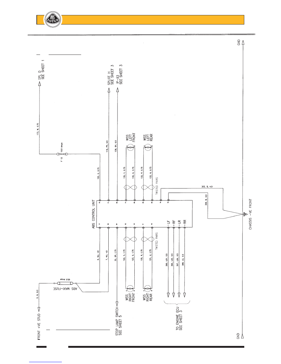
Circuit Diagram
5.
Diagnostic Trouble Codes