Lotus Elise / Lotus Exige. Instruction - part 60


  Index      Lotus     Lotus Elise / Lotus Exige (engine 1ZZ/2ZZ) - service repair instruction 2004 year


Search            


Content   ..  58  59  60  61   ..


Lotus Elise / Lotus Exige. Instruction - part 60


   Lotus Service Notes                                  Section JJ

Page 22

Anti-Lock Braking

Maximum braking force is provided from a tyre when there is around 15% slippage, dependent on road

surface conditions and tyre characteristics.  The function of the ABS is to limit tyre slippage when braking to
around this figure in order to provide optimum grip, and also, by preventing wheel lock, to ensure that steering
control of the vehicle is retained.

A high brake pedal pressure (or low road surface friction) may initiate the locking of one or more wheels.

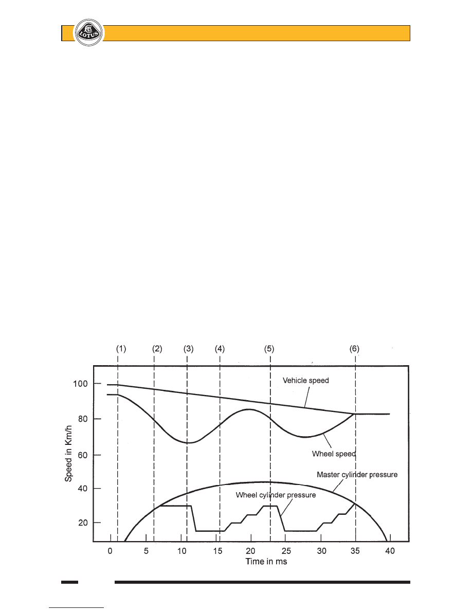
In the diagram below, a typical control strategy is shown:

1.

Normal braking occurs until, as the applied pressure increases, the wheel speed signals received by the
ECM indicate that the left hand front wheel (for example) is tending to lock. i.e. its deceleration is too
rapid, with too great a speed differential with the other wheels.

2.

The connection between the master cylinder and the LH front brake circuit is interrupted (by the isolation
valve), and the rate of slip increase is reduced.

3.

If the wheel speed continues to depart significantly from vehicle speed, the dump valve is energised to
reduce pressure in the LH front circuit until wheel speed begins to increase.  The dump valve is then
closed, as is the isolation valve.

4.

As wheel speed approaches that providing optimum grip, the isolation valve is pulsed open to allow a
stepped pressure increase.

5.

As wheel speed begins to drop off and depart from vehicle speed again, a new cycle starts, repeating
steps (1) to (4).

6.

When wheel speed increases sufficiently to meet vehicle speed, ABS intervention ceases, although
monitoring is continued throughout each braking event.

   Lotus Service Notes

                Section JJ

Page 23

Sequence of Operation

In the following diagrams, one half of the hydraulic modulator is shown schematically, representing the

front brake control circuit, with the sequence of operation described for the left hand front wheel brake.  This
sequence would be similar for any of the other three wheel brakes.  A typical emergency braking event is
described where, in this example, the left hand front wheel tends to lock.  Note that the complete system is
duplicated for the rear brake circuit, which remains completely independent of the front circuit.

Normal Braking

During normal braking, when the wheel speed sensors indicate no imminent wheel locking, the ABS is

inactive.  The solenoids are unenergised, so that the isolation valves are sprung open, and the dump valves
sprung closed.

Hydraulic fluid from the master cylinder enters the modulator via the inlet port, by-passes the attenuator

orifice, passes through the open isolation valve and out to the LH front wheel brake.

LHF

LHF

RHF

RHF

Isolation

Dump

Dump

Isolation

valve

valve

valve

valve

To LHF

To RHF

circuit

circuit

Inlet from
master
cylinder

Pump

Low pressure
accumulator

Pump motor

        j149a


   Lotus Service Notes                                  Section JJ

Page 24

Pressure Isolation (Pressure Maintain)

If signals received from the wheel speed sensors indicate imminent lock up of the LH front wheel, the first

step in the anti-lock sequence is to isolate that wheel brake circuit from the master cylinder.  The ECM ener-
gises the isolator valve solenoid, which closes the valve against spring pressure and maintains existing pres-
sure in the left hand front brake circuit regardless of any increase in pedal pressure.

Isolation valve
energised and
closed

Pressure
trapped
in LHF
brake
line

Inlet from
master
cylinder

        j149b

   Lotus Service Notes

                Section JJ

Page 25

Pressure Reduction

Once the LH front wheel brake circuit has been isolated from the master cylinder, the pressure must be

reduced in order to allow wheel speed to be restored.  This pressure reduction is achieved by the ECM energis-
ing the dump valve solenoid, which then opens against spring pressure and bleeds off some of the fluid into the
low pressure accumulator shared with the RH front circuit.  Very short activation pulses are used to maintain
close control of the pressure reduction, and to limit the reduction to that required to restore wheel speed.  Fluid
displaced from the wheel brake circuit is stored in the front brake accumulator against spring pressure, and is
also used to prime the hydraulic pump.

Isolation valve

Dump valve

energised and

energised and

closed

open

Fluid
bleeds
off from
LHF circuit

Inlet from
master
cylinder

Pump is
primed

Low pressure
accumulator
charged

        j149c


Content   ..  58  59  60  61   ..