Lotus Elise / Lotus Exige. Instruction - part 46


  Index      Lotus     Lotus Elise / Lotus Exige (engine 1ZZ/2ZZ) - service repair instruction 2004 year


Search            


Content   ..  44  45  46  47   ..


Lotus Elise / Lotus Exige. Instruction - part 46


Page 3


Lotus Service Notes   


     Section FJ

The clutch housing bolts to the back of the engine block and provides a dry chamber for the clutch mecha-

nism, and roller bearings for the gearbox input and output shafts.  The taper roller bearing for the differential 

RH output shaft is also accommodated.  The gearbox main case provides ball bearings for the two shafts, and 

houses gears 1 to 4 including the reverse gear pinion on its idler shaft.  The end cover or casing houses 5th 

and 6th gears.  On the 5-speed transmission, the 5th speed gears are overhung on the ends of the input and 

output shafts, but on the 6-speed, the alloy end cover contains ball bearings to support the ends of the two 

extended shafts, both of which are thus supported by a total of three bearings.  The housing for the final drive 

and differential is shared between the clutch housing and main case, with taper roller bearings supporting the 

differential case.

6-Speed Gear Clusters

The input shaft includes integral drive pinions for 1st, 2nd and reverse gears, and carries the clutch driven 

plate, the 3rd/4th synchroniser and the 5th/6th synchroniser, with the latter housed in the end cover.  The output 

shaft features an integral final drive gear, spline fixed 3rd/4th/5th/6th driven pinions, and carries the 1st/2nd 

gear synchroniser.  All forward gears are constant mesh with inertia lock type synchromesh, with reverse gear 

attained by sliding a spur idler pinion into engagement with both a gear on the periphery of the 1st/2nd syn-

chroniser and a drive gear integral with the input shaft.  All gears, with the exception of reverse, use a helical 

tooth form for quiet running.

Sychromesh:  For each gear ratio, one of the shafts has a fixed gear, and meshes with a freely revolving gear 

on the other shaft.  To engage a particular gear, the freely revolving gear must be connected to its shaft via 

the sychro hub.  As an example, third gear operates as follows:  Under normal road driving, when the clutch is 

depressed as a precurser to a gear change, the input shaft with the third gear synchroniser are de-coupled from 

the engine, but will be turning under decaying inertia, clutch windage and oil drag, from the drive pinions (which 

in this condition are being driven by the output shaft).  Third gear pinion on the input shaft is driven by the fixed 

gear on the output shaft, which itself is driven by the roadwheels.  Before the outer sleeve of the synchroniser 

may be slid on its axial splines to engage with the spline ring integral with third speed input shaft gear, the speeds 

of the two parts must be commonised.  To aid this process, a sychroniser/baulk ring is fitted between the two 

parts, being rotationally driven by the synchroniser, and equipped with a female conical surface to mate with a 

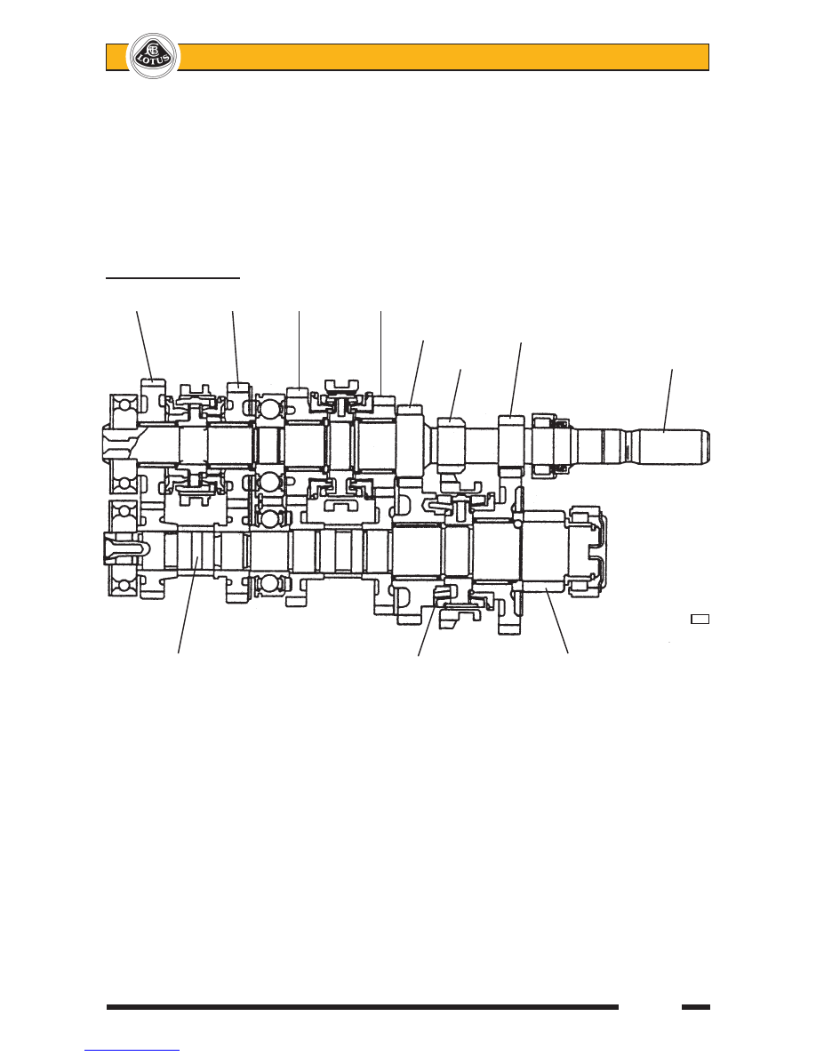
6th gear              5th gear     4th gear    3rd gear 


                                   2nd gear     1st gear 

                                         Reverse                     Input shaft


f130

  Output shaft                  Double cone 2nd          Final drive gear

                            gear synchromesh


Lotus Service Notes   


     Section FJ

Page 4

male cone integral with the gear.  Teeth on the outside of the synchro ring, over which the synchro sleeve must 

slide before engaging the third gear splines, perform a baulking function described below: 

When the gear lever is operated, the outer sleeve of the synchroniser is pushed towards third gear, and 

pushes three spring detent plates which press the synchro ring onto the gear cone.  As the input shaft train 

is turning faster than third gear, the synchro ring is dragged to one end of its rotational constraint slots in the 

synchroniser, in which position the internal spline teeth of the synchroniser sleeve are mis-aligned with the teeth 

on the outside of the synchro ring.  When further pressure is applied via the gearlever, the detent plates are 

overidden, and the synchroniser sleeve splines are pressed against the ends of the sychro ring teeth, increasing 

the pressure on the conical surfaces.  The bevelled ends of the sleeve splines and synchro ring teeth tend to 

turn the ring into alignment, but whilst a speed differential between the ring and the gear remains, the cone drag 

force (caused by gear inertia) is dominant and maintains spline mis-alignment.  This is the 'baulk' function.  

When the speed of the input train is synchronised to that of third gear, there ceases to be a force dragging 

the synchro ring to the end of its slots, such that the force at the bevelled ends of the splines is now dominant,  

allowing the synchro ring to move back in its slot to align the splines and for the synchroniser sleeve to be slid 

over the ring teeth towards the spline teeth on third gear.  These teeth, whose position in relation to those on 

the synchro ring was entirely at random when speed synchronisation occurred, are unlikely to align, but are 

now freed to turn under the action of the spline end bevels, since once the synchroniser sleeve is slid over the 

sychro ring teeth, there is no longer any pressure applied to the cones.  The sleeve completes engagement by 

sliding over the gear spline teeth to connect the synchroniser with the gear.

On 6-speed transmissions, in order to cater for the heavy demands made on the second gear synchroniser, 

and provide high durability, this gear is fitted with a double cone mechanism to increase the conical surface 

area within a small space.

The selector mechanism cross shaft uses Teflon bushes to minimise friction, and a mass damper to improve 

gearchange feel.  A slotted interlock cage allows the selector finger to operate only one selector shaft at a time.  

In order to inhibit the unintended selection of reverse gear, a spring detent mechanism is arranged to act on the 

cross-shaft, in conjunction with, on 6-speed versions, a lift collar at the gearchange lever, and on 5-speeders, 

a mechanism allowing selection of reverse gear only on approach from the central neutral position. 

Differential

Standard cars use a conventional 'open' two bevel gear differential contained in a housing bolted to the 

final drive output gear, and supported in two taper roller bearings.  Optional on some models, in conjunction 

with electronic Lotus Traction Control (LTC), is a Torsen type limited slip differential (LSD) in an otherwise un-

changed transmission housing (Character 3 of 7 digit code on bar code label: 'O' = open; 'L' = LSD).  The LSD 

uses worm wheels to interconnect the two output shafts and uses the poor torque reversal efficiency of this 

type of gearing to ensure that both wheels are always supplied with driving torque. 

Driveshafts

An output extension shaft supported in a ball bearing mounted on the cylinder block, is used on the right 

hand side to allow equal length drive shafts to be used.  The driveshafts use Rzeppa type joints on their out-

board ends and plunging joints at the inboard ends to accommodate the driveshaft length variation concomitant 

with suspension travel.

FJ.2 - GEARCHANGE MECHANISM

6-Speed

The gear lever is spring biased towards 

the 3rd/4th gear plane, and must be moved 

against light spring pressure to the left before 

selecting first or second gear, or against similar 

pressure to the right before selecting 5th or 

6th speed.  

Engaging Reverse Gear:

With the vehicle at a 

complete standstill, pause for a moment with the clutch pedal fully depressed be-

fore moving the lever to the left, raising the lift collar beneath the knob, and then further to the left over a spring 

detent before finally pushing forwards to engage the gear.  


          LIFT

      COLLAR

  6-SPEED CHANGE  PATTERN            

ohs15a

Page 5


Lotus Service Notes   


     Section FJ


                    Crossgate            Gearchange Cable Schematic (prior May '07)


                         Shift

                    Reverse gate lift collar

Reverse

gate                 Crossgate                               Crossgate cable

release               bellcrank lever                

cable                                                                Shift cable

Gear lever 

ball pivot           Reverse gate    Abutment 

                stop arm       block                                  

f133


5-Speed

The gear lever is spring biased towards 

the 3rd/4th gear plane, and must be moved 

against light spring pressure to the left before 

selecting first or second gear, or against similar 

pressure to the right before selecting 5th.


Engaging Reverse Gear:

With the vehicle at a 

complete stand-

still,  pause  for  a  moment  with  the  clutch 

pedal fully depressed before moving the lever 

against spring pressure fully to the right, and 

then rearwards to engage the gear.  Note that 

an inhibit mechanism requires that the lever 

approaches reverse gear only from the central 

neutral position.  Direct access from 5th gear 

is blocked.

 A two cable mechanism is used to connect the gearchange lever with the transmission, one cable ('shift') 

to transmit the fore/aft movement of the lever, and a second ('crossgate') cable for the sideways movement.  

The gearchange lever is pivotted at its base and operates the shift cable directly via a ball joint half way up the 

lever.  The base of the lever has an extended ball pin on the right hand side which engages with a crossgate 

bellcrank lever, the other leg of which operates the crossgate cable.  An inhibit mechanism prevents the gear 

lever being moved into the reverse gear plane unless a collar beneath the gear knob is lifted.  Prior to May '07, 

the collar is connected by control cable to a pivotted stop arm sprung to an 'up' position.  In this position, a stop 

pin on the crossgate bellcrank lever abuts against the end of the stop arm and prevents gearlever movement 

into the reverse gear plane.  When the collar is lifted, the stop arm is pulled down against its spring, to clear 

the stop pin and allow reverse gate selection.  From May '07, lifting the collar raises a boss at the base of the 

lever above a curved inhibitor block, allowing the lever full leftward movement.


  5-SPEED CHANGE  PATTERN               

ohs15b


Lotus Service Notes   


     Section FJ

Page 6

The front end of both inner cables are equipped with socket joints which may be clipped on and off the ball 

pins provided on the gearchange mechanism.  The outer cables are retained by a forked plastic block bolted 

into the gearlever/handbrake mounting frame.  

The gear cables are routed along the centre of the cabin floor, beneath the fuel tank bay, and loop under 

the engine to an abutment bracket on the top of the transmission housing.  Both cables are retained in the 

abutment bracket by spring 'C' clips.  The shift cable is fitted on the left, and uses a bellcrank lever and ball 

jointed link to connect with the transmission cross-shaft lever, in order to rotate the shaft.  The cross-shaft lever 

incorporates an inertia weight to smooth the gearchange action and improve feel.  The crossgate cable is fitted 

on the right and uses a centre pivotted lever arm to impart an axial motion to the transmission cross-shaft.  The 

ends of both inner cables threaded into alloy eyes which are retained on the lever pins by 'R' clips.

Gearchange Cable Adjustment

Under normal circumstances, no adjustment to the gear cables should be required.  If a cable is replaced 

in service, it may be necessary to make minor adjustments via the threaded ball joint at the front of the cable 

in order to accommodate lever movement within the shroud aperture.   

Gearchange Cable Replacement

For access to the gear cables, the gear lever shroud and parking brake lever trim must be removed: Un-

screw the gear lever knob, remove the single screw each side of the shroud, and withdraw the shroud over the 

gear and parking brake levers.  Remove the engine bay undertray.

At the front end of the cables, unclip the inner cable ball joint sockets from the ball pins on the mechanism 

levers.  Release the outer cable plastic abutment block from the mounting frame.  At the rear end of the cables, 

remove the 'R' clips retaining the inner cable eyes to the levers, and the 'C' clips securing the outer cables to 

the abutment bracket.  Release the 'P' clips and cable ties as necessary to allow the cables to be withdrawn 

from the car, noting the routing of the cables past the parking brake lever and wiring harness.

Refit in reverse order to removal, paying particular attention to the routing through or alongside the park-

ing brake lever mounting frame.

Transmission                'R' clip        'C' clip

External Levers

                                          Shift bellcrank lever

                                                Crossgate cable

            Crossgate

Inertia        lever                                          Shift cable

weight

Transmission

cross-shaft

housing                            


f132


Content   ..  44  45  46  47   ..