Snowmobile Arctic Cat (2002 year). Instruction - part 173
9-170
13. Using Shock Retaining Blocks (p/n 0644-142) to
hold the shock in place and using an adjustable
wrench, tighten the end cap securely.
AP016DA
14. Apply a light coat of oil on the bladder housing O-
ring; then install the brass bladder housing into the
lower end cap. Tighten securely.
AP014
15. Pressurize the shock (see Pressurizing Rebuildable
Shocks section). After shock has been pressurized,
install screw into bladder housing. Tighten
securely.
16. Install shock eyelet bushings and axle.
Servicing Front Arm
Quick-Adjust Shock
REMOVING
1. Remove the shock from the snowmobile.
NOTE: When removing the shock from the snow-
mobile, it will be necessary to disconnect the
adjuster assembly. Before disconnecting the
adjuster, the adjustment knob must be turned
completely open (counterclockwise) so there is no
pressure on the line. To prevent oil spillage, place
a protective cap on the hose end.
2. Wash the shock body in parts-cleaning solvent;
then dry with compressed air to remove sand and
dirt.
AG807
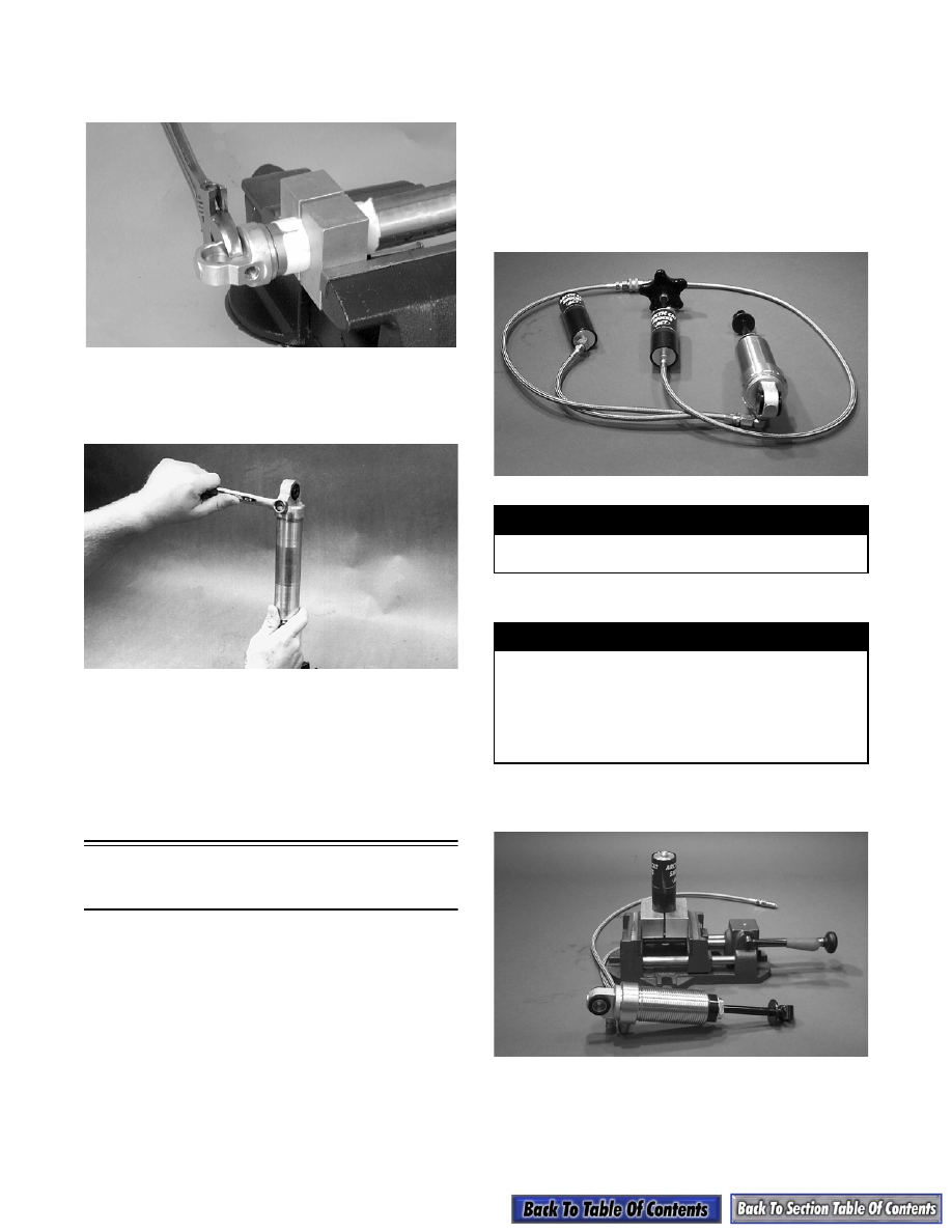
DISASSEMBLING
1. Using the Shock Retaining Blocks (p/n 0644-142),
place the remote reservoir in a vise.
AG808
2. Remove the valve screw from the pressure valve.
! WARNING
When using compressed air to dry components,
always wear safety glasses.
! WARNING
Before any work can be performed on the gas
shock absorber, first discharge all pressure from
the shock remote reservoir. Remove the valve
screw from the pressure valve and insert the Shock
Inflation Needle (p/n 0644-158). Open valve until all
pressure is released. Failure to do this may cause
personal injury.