Snowmobile Arctic Cat (2002 year). Instruction - part 161
9-122
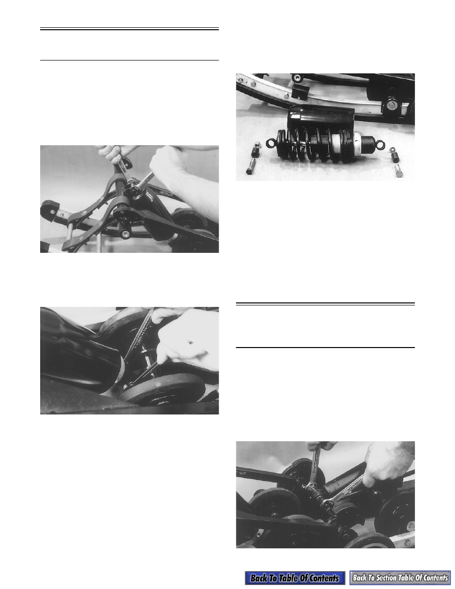
Front Arm Shock
Absorber
NOTE: The skid frame must be removed for this
procedure.
DISASSEMBLING
1. Remove the cap screw and lock nut securing the
upper shock absorber eyelet to the front arm.
Account for a bushing.
AG306
2. Remove the cap screw and lock nut securing the
lower shock eyelet to the front shock bracket.
Remove the shock absorber and account for a
bushing.
AG317
3. Slide the rubber shock boot off the shock absorber.
INSPECTING
NOTE: Whenever a part is worn excessively,
cracked, or damaged in any way, replacement is
necessary.
1. Inspect the shock absorber for any signs of oil
leakage especially at the point where the shock
shaft enters the shock body.
2. Inspect the shock absorber eyelet welds (at each
end) for any cracks or signs of separation.
ASSEMBLING
1. Apply a light coat of grease to both bushings and
install the bushings into the shock absorber eye-
lets.
AG318
2. Position the lower shock absorber eyelet into the
crossbrace bracket and secure with a cap screw
and lock nut. Tighten to 3.2 kg-m (23 ft-lb).
3. Position the upper shock absorber eyelet into the
front arm bracket and secure with a cap screw
(coated with red Loctite #271) and lock nut.
Tighten to 3.2 kg-m (23 ft-lb).
NOTE: Do not over-tighten the shock cap screws
as the shock eyelets must be free to pivot.
Rear Arm
Shock Absorber
And Shock Links
NOTE: The skid frame must be removed for this
procedure.
DISASSEMBLING
1. Remove the cap screw and lock nut securing the
lower shock absorber eyelet and shock links to the
pivot tube bracket. Account for the two shock link
axles.
AG314