Index Snowmobiles / ATV Snowmobile Arctic Cat - instruction 2002 year
Search
Content .. 95 96 97 98 ..
Snowmobile Arctic Cat (2002 year). Instruction - part 97
0737-338
6-40
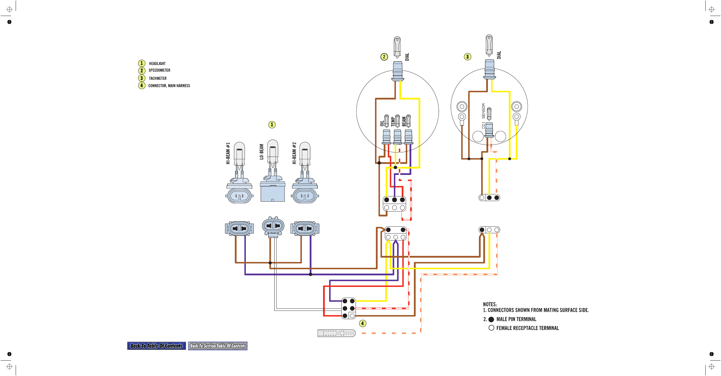
Harness
V
(p/n 0686-699)