Snowmobile Arctic Cat (2002 year). Instruction - part 78
5-31
5
B170
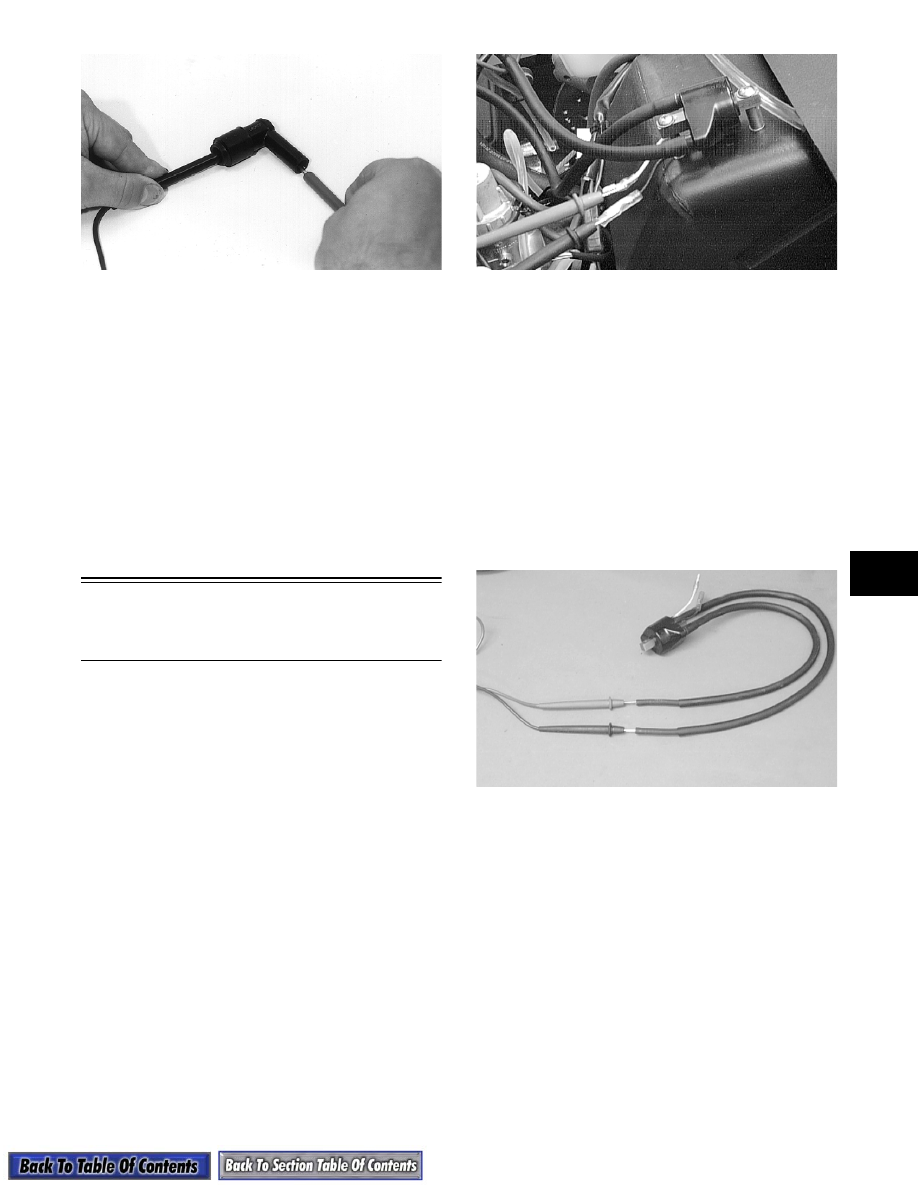
4. Spark-plug cap resistance must be between 4000-
6000 ohms.
IGNITION SWITCH
1. Remove the main wiring harness connectors from
the ignition switch.
2. Rotate the key to the OFF position.
3. The meter must read less than 1 ohm of resistance
between the ignition switch terminals.
4. Rotate the key to the RUN position.
5. The meter must indicate OL (infinite resistance).
Testing Electrical
Resistances
(600 cc Triple Model)
NOTE: Resistance tests of the engine electrical
components should be made using the Fluke Mul-
timeter only. Analog-style multitesters may not be
accurate enough to use in these critical tests.
Replace any component that does not have a test
value within specifications.
IGNITION COIL (Primary)
1. Disconnect the spade connectors from the ignition
coil body.
2. Set the selector in the X1 position.
3. Connect the red meter lead to the positive spade
terminal; then connect the black meter lead to the
negative spade terminal.
AK051D
4. Ignition coil primary resistance must be between
0.29-0.39 ohm.
IGNITION COIL (Secondary)
1. Remove the spark-plug caps from the high tension
wires.
2. Set the selector in the X1K position.
3. On the dual lead coil, connect the red meter lead to
one high tension wire; then connect the black
meter lead to the other high tension wire.
4. On the single lead coil, connect the red meter lead
to one high tension wire; then connect the black
meter lead to the positive spade terminal.
AK050D
5. Ignition coil secondary resistance must be between
6320-9480 ohms on both coils.
DC POWER COIL
NOTE: On APV-equipped carbureted models, the
traditional charge coil(s) have been replaced by a
single DC power coil on the stator.
1. Disconnect the two plugs (red/yellow and yellow/
red) from the CDI unit to the DC power coil.
2. Set the selector in the X1 position.
3. Connect the red meter lead to one wire; then
connect the black meter lead to the other wire.
4. DC power coil resistance must be between 0.71-
1.07 ohms.