Snowmobile Arctic Cat (2002 year). Instruction - part 38


  Index      Snowmobiles / ATV     Snowmobile Arctic Cat - instruction 2002 year


Search            


Content   ..  36  37  38  39   ..


Snowmobile Arctic Cat (2002 year). Instruction - part 38


2-135

2

AP118C

AP117

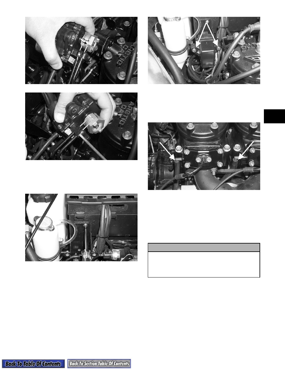
22. Position the tab (on the bottom of the servomotor

mounting plate) into the slot in the air-intake

silencer; then secure the mounting plate to the

silencer with a screw.

AP127

23. Place the servomotor with cover into position on

the mounting plate; then secure with two cap

screws.

AP116A

24. Check APV cable adjustment. See Arctic Power

Valve (APV) System in Section 3.

25. Connect the two APV drain hoses making sure

they are not in contact with hot or moving parts.

AP128A

26. Turn the gas tank shut-off valve to the OPEN

position.

27. Start engine and verify ignition timing.

28. Test drive or run the snowmobile and recheck the

coolant level after 5-6 minutes. Tighten the drive

clutch cap screw to 7.6 kg-m (55 ft-lb).

! CAUTION

If the engine had a major overhaul or if any major
component was replaced, proper engine break-in
procedures must be followed. If the proper
engine break-in procedures are not followed,
severe engine damage may result.

2-136

Installing Engine

(Triple Models)

1. Secure the four engine mounting brackets to the

crankcase. Tighten the cap screws securing the

front and right-side rear brackets to 2.4 kg-m

(17 ft-lb). Tighten the rear PTO-side bracket to

1.4 kg-m (10 ft-lb).

2. Place the engine assembly in the engine

compartment. Place the recoil starter into position

and secure with four cap screws and lock washers.

Tighten to 0.7 kg-m (5 ft-lb).

AN150

3. Place the resonator into position; then secure with

the cap screws, washers, bushings, spacers, and

retainer nuts.

„

NOTE: On models equipped with electric start,

make sure the battery ground cable and star
washer are properly positioned.

4. Connect the temperature-gauge sender wire.

AJ159

5. Place the coolant hoses into position and secure

with the clamps.

6. Connect the cable to the oil-injection pump and

secure with the nylon washer and E-clip; then

connect the oil-supply and oil-output hoses and

secure with the clamp. Bleed the oil-injection

system (see Fuel System - Related Items in

Section 4).

AN009

7. Connect the impulse hose to the crankcase.

8. Secure the right-side front and rear and left-side

front engine mounts to the front end making sure

the mounts are properly positioned. Tighten the

cap screws and nut to 2.8-3.5 kg-m (20-25 ft-lb).

AN611D

9. Adjust the torque bumper to allow a clearance

between the engine and the torque bumper of

1.78 mm (0.070 in.) on the 1000 cc or 1.5 mm

(0.060 in.) on the 600 cc; then secure the adjust-

ment by tightening the jam nuts.

10. Place the carburetors into position and secure with

the flange clamps. Synchronize the oil-injection

pump (see Fuel System (Related Items) in Section

4).

AN614D

2-137

2

11. Connect the main wiring harness, ignition timing

sensor wiring harness, and the spark-plug caps.

Secure the two brown ground wires to the magneto

housing with a cap screw.

AQ125

12. In order, place the expansion chambers and grafoil

gaskets into position. Secure the expansion

chambers to the header pipes and resonator with

the springs. Secure the expansion chambers to the

front end with the long spring.

13. Connect the hood cable to the cable hook; then

secure the hook.

„

NOTE: Before installing the drive clutch, be sure

to wipe both the crankshaft taper and clutch
mounting taper clean using a clean towel.

14. Place the drive clutch into position on the

crankshaft making sure the two sleeves are

properly positioned (see Section 8) and secure

with the clutch bolt and lock washer. Tighten to

6.9-7.6 kg-m (50-55 ft-lb). Install the belly pan

plug.

AF477D

„

NOTE: Apply a coat of Anti-Seize Thread Com-

pound (p/n 0678-146) to the keyway end of the
driven shaft.

15. Install the driven pulley, stub shaft, key, and

washers (see Section 8). Secure with a cap screw.

Tighten to 2.6-3.3 kg-m (19-24 ft-lb).

SC013D

16. Check drive clutch/driven pulley alignment (see

Section 8).

17. Install the drive belt. Check belt deflection (see

Section 8). Secure the belt guard.

18. Fill the cooling system (see Section 3); then install

the coolant filler cap.

19. Bleed the oil-injection system (see Fuel System  -

Related Items in Section 4).

„

NOTE: Steps 20 through 24 are for APV equipped

engines.

20. Slide the cable drums into the servomotor

actuator; then place the cable housings into

position in the servomotor. Secure the cable

housings with the holder.

AP118C

AP117

2-138

21. Position the tab (on the bottom of the servomotor

mounting plate) into the slot in the air-intake

silencer; then secure the mounting plate to the

silencer with a screw.

AP127

22. Place the servomotor with cover into position on

the mounting plate; then secure with two cap

screws.

AP116A

23. Check APV cable adjustment. See Arctic Cat

Power Valve (APV) System in Section 3.

24. Connect the two APV drain hoses making sure

they are not in contact with hot or moving pats.

AP128A

25. Turn the shut-off valve to the OPEN position.

26. Check ignition timing.

27. Test drive the snowmobile and recheck the coolant

level after 5-10 minutes. Retighten the drive clutch

to 7.6 kg-m (55 ft-lb).

! CAUTION

If the engine had a major overhaul or if any major
component was replaced, proper engine break-in
procedures must be followed. If the proper
engine break-in procedures are not followed,
severe engine damage may result.


Content   ..  36  37  38  39   ..