Snowmobile Arctic Cat (2002 year). Instruction - part 15


  Index      Snowmobiles / ATV     Snowmobile Arctic Cat - instruction 2002 year


Search            


Content   ..  13  14  15  16   ..


Snowmobile Arctic Cat (2002 year). Instruction - part 15


2-43

2

AN233

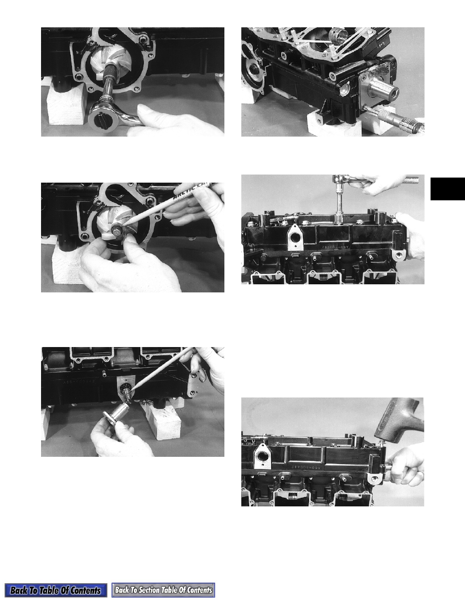
24. Using a plastic hammer, gently tap on the head of

the cap screw until the impeller is free of the shaft.

Remove the cap screw and impeller.

AN232

25. From the opposite side of the crankcase, remove

the oil pump retainer and shaft. Account for the

shaft thrust washer located between the retainer

and shaft flange.

AN231

26. Using an impact driver, remove the four screws

securing the seal protector plate to the end of the

crankcase; then slide the plate free of the

crankshaft.

AN230

27. Remove the 14 cap screws securing the two

crankcase halves together.

AN229

28. To separate the crankcase halves, start two of the

crankcase cap screws into the crankcase at

opposite corners. Thread the cap screws into the

crankcase until a 6.4 mm (1/4 in.) space remains

between the cap screw flange and the crankcase

surface.

29. Set the crankcase on its side with the flat reed

surfaces resting on the work bench. Using a

hammer, strike the heads of the two cap screws

alternately driving the two case halves apart.

AN227

30. Once there is a 6.4 mm (1/4 in.) space between the

two case halves, set the crankcase down on the

work bench with its bottom side up. Remove the

cap screws; then lift the bottom of the crankcase

free of the engine.

2-44

AN221

31. Grasp the crankshaft at either end and carefully lift

it from the crankcase. Have a clean area ready to

lay the crankshaft on once it has been removed.

Account for the two crankcase dowel pins.

AN222

32. With the crankshaft removed from the top half of

the crankcase, remove the seven bearing retaining

pins and the C-ring.

AN223

„

NOTE: Do not replace the inner oil seal or

mechanical seal unless the water pump shows
signs of leaking coolant out of the small bleed hole
in the bottom half of the crankcase. If a water
pump seal is to be replaced, use the Water Pump
Bearing and Seal Kit (p/n 0644-084).

33. Place the crankcase on the bench with the water

pump side down. Using the long seal driver, drive

the water pump seal from the crankcase.

AN226

34. Using a pair of snap ring pliers, remove the snap

ring securing the inner seal in the crankcase.

35. Using the hooked end of the seal driver, pull the

inner seal free of the crankcase.

AN224

36. Using a sharp-pointed tool, pry the seal ring from

the backside of the water pump impeller.

AN051

2-45

2

Disassembling Engine

(1000 cc Models)

„

NOTE: If servicing the exhaust manifolds,

remove them at this time.

1. Using an impact driver or a 6-mm hex wrench,

remove the four cap screws securing the magneto

case to the crankcase. Account for the dowel pins.

2. Using an impact driver, remove the five screws

securing the water pump cover. Remove the cover

and account for the O-ring seal and two dowel

pins.

AQ005

3. Secure the crankshaft using a spanner wrench;

then remove the cap screw securing the water

pump impeller.

AQ006

4. Remove the water pump impeller from the

counterbalance shaft.

5. With the impeller removed, check the condition of

the seal on the back side. It must be free of any

cracks, chips, or rough areas.

„

NOTE: If any rough areas are found, the seal ring

can be removed using a small screwdriver. Simply
pry the seal ring upward; then remove the rubber
cup from beneath the seal ring.

AQ008

6. Remove the remaining water pump center and

back section from the counterbalance shaft.

7. Inspect the front mechanical seal and rear seal

surface for any rough areas. If the seals need

replacement, see the appropriate Repairing Water

Pump in Section 3.

AQ010

8. Using a spanner wrench to secure the crankshaft,

remove the cap screw, lock washer, and large flat

washer securing the flywheel.

9. Remove the three cap screws securing the starter

pulley to the flywheel.

10. To prevent damaging the crankshaft threads during

the flywheel removal procedure, use the Puller

Insert (p/n 0644-179) on the end of the crankshaft.

AQ019

2-46

11. Attach the flywheel puller to the flywheel using

three 8-mm cap screws approximately 2 3/4 in.

long. Thread each of the three cap screws evenly

into the flywheel 1/2 in.

12. Tighten the center puller bolt against the insert on

the crankshaft. Continue to tighten the puller bolt

until the flywheel snaps free of the crankshaft

taper. Remove the puller from the flywheel and

place the flywheel, open side up, on a clean work

bench. Account for the flywheel key.

AQ020

13. Remove the Allen-head cap screws securing the

stator to the stator plate.

14. Remove the rubber grommet from the crankcase

and slide the stator free of the crankshaft.

AQ021

15. Remove the three Allen-head cap screws securing

the stator plate to the crankcase.

16. Remove the thermostat cover; then remove the

thermostat from the water manifold.

„

NOTE: The thermostat is designed to open at

50°C (122°F). It should be checked for proper oper-
ation before installing (see Section 3).

17. Remove the water manifold assembly.

18. Remove the heads from the cylinders. Account for

the two O-rings under each head.

19. For assembly purposes, number the three heads

and cylinders. Start from the MAG-side.

AQ026

20. Remove the four nuts, lock washers, and flat

washers securing each cylinder to the crankcase;

then carefully lift each cylinder straight up and

free of the piston. Support the piston as the

cylinder clears the piston to prevent the connecting

rod from dropping against the crankcase and

causing damage to the crankcase sealing surface.

AQ027

21. For assembly purposes, number the dome of each

piston starting from the MAG-side; then remove

the MAG-side circlip from each piston.

AQ028

22. Using Piston Pin Puller (p/n 0644-328), remove

the piston pin from each piston. Remove the

piston, piston pin bearing, and the two shim

washers. Keep each piston, piston pin, and bearing

together as a set.


Content   ..  13  14  15  16   ..