Snowmobile Yamaha Phazer PZ50 (2007-2008 year). Instruction - part 100
9-53
SPEC
C
F
G
H
I
I
J
K
L
9
0
A
B
C
C
C
D
E
1
1
1
2
3
4
5
5
5
6
6
6
7
M
N
O
P
Q
R
S
T
U
V
W
X
Y
Z
[
\
]
^
a
b
b
b
c
c
c
c
d
e
f
g
h
i
A
A
B
B
C
A-A
B-B
8
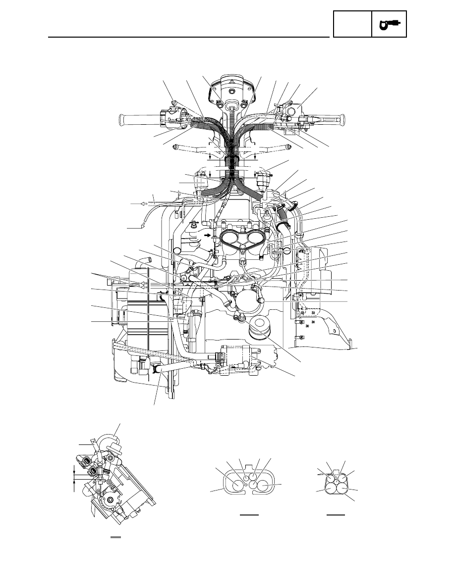
CABLE ROUTING
|
|
|
9-53 SPEC C F G H I I J K 9 0 A B C C C D E 1 1 1 2 3 4 5 5 5 6 6 6 7 M P S T U V W X Y Z [ \ ] ^ a b b b c c c c d e f g h i A A B B C A-A B-B 8 CABLE ROUTING |