Snowmobile Polaris Two Stroke (2007 year). Instruction - part 62


  Index      Snowmobiles / ATV     Snowmobile Polaris Two Stroke - instruction 2007 year


Search            


Content   ..  60  61  62  63   ..


Snowmobile Polaris Two Stroke (2007 year). Instruction - part 62


9.31

REAR SUSPENSION

9

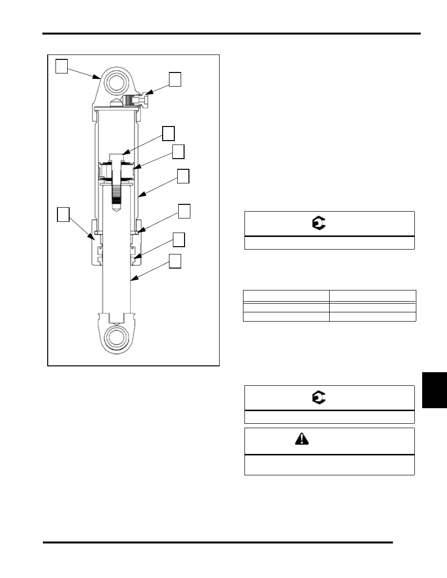
Walker Evans Shocks (7043234, 7043233)

This type of shock has some critical servicing items that you will
need to address when servicing these shocks. There are three
ways that you can adjust the performance of the shock; by
adjusting the shim stack, adjusting the fluid level and adjusting
the pressure. 

Shim stacks can be adjusted just like any other shock.

Nitrogen pressure must be 215 psi (14.8 bar) for these shocks
(7043234, 7043233).

Fluid level must be at 70cc for the front track shock and 95 cc
for the IFS shock.

IMPORTANT: Some important notes when rebuilding

these shocks are listed in bullet points below.

• Protect the shock rod with supplied sleeve when 

removing or installing the shock on the vehicle.

• When charging or discharging the shock always have 

the shock rod facing downward.

• Fluid level and Nitrogen pressure are critical.

1.

Place the body cap (1) of the shock in the vise so that the
shock rod (2) is facing downward. 

2.

Remove the service port screw (3) and release the pressure
with the shock charging needle.

3.

Make sure that all pressure is out of the shock or oil may
spray out in step 5.

4.

Place the body cap (1) in the vise, so that the shock rod (2)
is facing upward.

5.

Slowly loosen the shock rod bearing cap (4) and remove it
from the shock.

6.

Empty all the shock oil from the shock body and discard
the old oil. 

7.

At this time you can service or adjust the valve stack (5) as
needed. 

8.

If service or adjustment was done at this time torque the
piston retaining bolt (6) to 25-30 ft-lb (34-41 N-m).

9.

If needed remove the body cap and install a seal (7)/O-ring
(8) kit. 

10. Place the specified amount of fluid into the shock body.

IMPORTANT: Be sure to only insert the required

amount of 5wt shock fluid -2cc / + 1cc. If more than the

specified amount is inserted shock damage will

occur.

11. Insert and torque down the shock rod assembly into the

shock body (9) to 85 ft-lb (115 N-m).

12. Flip shock over in the vice so that the shock rod is facing

downward.

13. Pressurize the shock to 215 psi (14.8 bar).

IMPORTANT: Fill shock with Nitrogen to 215 psi (14.8

bar). Do not fill the shock and re-check. The volume in

3

1

6

7

2

9

4

5

8

T 

Piston retaining bolt: 25-30 ft-lb (34-41 N-m)

S

HOCK

 PN

F

LUID

 L

EVEL

7043234 (FTS)

70cc

7043205 (RTS)

95cc

T 

Body Cap Torque: 85 ft-lb (115 N-m)

CAUTION

Do not over torque the shock rod bearing cap or 

shock performance will be compromised.

9.32

REAR SUSPENSION

the gauge will deplete the pressure in the shock and

will affect performance.

14. Check for any leaks.

15. Protect the shock rod (2) and carefully place it back onto

vehicle.

Ryde Fx Mono-tube Shock Disassembly

Procedures for the proper disassembly and assembly of RydeFX
gas charged IFP and emulsion mono-tube shock absorbers.

1.

Remove the shock(s) from the vehicle.

2.

Before unscrewing pre-load springs, measure the
compressed length of the installed spring and mark position
for reinstallation.

3.

If the shock incorporates a spring, remove the spring and
all collateral retainers.

4.

Wash the shock body in parts cleaner; then dry with
compressed air to remove sand and dirt.

5.

Remove bearing, sleeve and/or bushings from lower shock
mount eyelet. Secure the lower mount of the shock in a vise.
The use of soft jaws is recommend to prevent damage or
marks to the shock.

6.

Remove the small button head screw from the pressure
valve assembly.

7.

Depressurize the shock.

8.

Internal Floating Piston Shocks, using a slotted
screwdriver, loosen the pressure valve assembly counter-
clockwise two full revolutions allowing the gas pressure to
fully escape past the pressure valve assembly O-ring.

9.

Emulsion Shocks: With the shock inverted and the piston
rod fully extended, secure the lower mount of the shock in
a vise. Allow a couple of minutes for the gas pressure to
separate from the oil and rise to the top. Using a rag as a
shield to prevent spraying gas and oil; place rag over top
the pressure valve assembly and slowly loosen the valve
assembly with slotted screw driver three full revolutions,
allowing all the gas pressure to escape past the pressure
valve assembly O-ring.

10. Allow all the gas pressure to escape before proceeding with

the removal of the pressure valve assembly. Pressurized gas
and shock oil could eject the valve assembly from the
cylinder resulting in bodily injury.

11. Using a slotted screwdriver, remove the pressure valve

assembly from the lower end mount. Account for an O-ring.

12. Using an adjustable face spanner (PN PS45262), fully

loosen and remove cylinder head assembly.

13. Pour the oil out of the shock body. Discard old oil into an

approved storage container and dispose appropriately.
Never reuse damper oil during shock rebuild.

14. Using the I.F.P extraction tool thread the tool into the I.F.P

and pull upwards, removing the I.F.P from the shock body.
Account for wear band and an O-ring. Note: Not applicable
for emulsion shock

15. Clean the inside of the shock body using clean parts-

cleaning solvent and blow dry using compressed air.

16. Place the shock piston rod upper mount in bench vise, begin

piston and valve removal. Arrange parts removed in the
sequence of disassembly. The piston should have the flat
slots facing the nut end (as highlighted in black).

17. Items to inspect: Piston rod for straightness, nicks or burrs.

Cylinder Head Assembly / DU Bearing clean, inspect, or
replace. Inside of shock body for scratches, burrs or
excessive wear. Teflon piston and I.F.P wear band for cuts,
chipped or nicked edges, or excessive wear. O-rings for
nicks, cuts, or cracks. Cap and rod seals for nicks, cuts or
cracks. Valve discs for kinks or waves. Compression
bumpers (ski shocks only) for chipping, cracking or
missing. Should any of these items be in question
replacement is recommended.

Ryde Fx Mono-tube Shock Assembly

1.

Place the piston rod upper mount into the vise. Reassemble
damper rod assembly in the reverse order of disassembly.
Special attention should be paid the order of the Rebound
and Compression disc (shim) stacks, ensuring that they are
in the same order prior to disassembly. Tighten the lock
nut to 15-20 ft-lb. of torque. DO NOT OVER-TORQUE.
If excessive torque is applied, damage to the piston and
valves will occur.

2.

Secure the shock body by its lower mount in vise. The use
of soft jaws is recommend to prevent damage or marks to
the shock. It is important that the gas shock be retained in
the vice by the lower mount. Any other method of securing
the shock body during these procedures may deform the
shock body cylinder.

NOTE:  The next points on IFP are not applicable for
emulsion shocks. Proceed to assembly of the
pressure valve.

3.

Thread the positioning head onto the I.F.P locator tool and
adjust the top of the value indicator to the appropriate
measurement. Depending on which shock absorber is being
worked on, adjust the piston location tool to the specified
depth indicated in the shock specification chart.

4.

Apply a thin film of oil onto the floating wear band and O-
ring and install the floating piston into the top of the shock
body, positioning it below the counterbore. 

5.

Using the tool as a handle, push the floating piston down
into the shock body, being careful not to damage I.F.P wear
band and O-ring, until the value indicator knob comes in
contact with the shock body. The piston should now be
located correctly.  

6.

Screw the pressure valve assembly into the valve port by
hand with a slotted head screwdriver; and tighten to 100-
110 in.lb of torque. 

7.

Fill the shock body with shock oil. Internal Floating Piston
Shocks: Fill the shock body with shock oil to the bottom of

9.33

REAR SUSPENSION

9

the thread within the cylinder. Emulsion Shocks: Fill shock
body with 110cc's of oil. This will allow for the required
air space to properly gas charge the shock with nitrogen gas.

NOTE:  After filling the shock body with oil, allow a
couple of minutes for all air bubbles to rise to the
top. 

8.

With the cylinder head assembly pushed down against the
piston, carefully, insert the piston rod and assembly into the
cylinder; Slightly oscillating the piston rod to allow piston
to enter shock body bore. A light coating of oil on the piston
wear band will ease installation. 

9.

Slowly push the piston rod and assembly into shock body
until the cylinder head assembly bottoms on the cylinder
counterbore. Slight up and down movement may be
required to allow all air to pass through piston assembly.

10. During installation, some shock oil will overflow. Wrap a

shop cloth around shock body to catch possible oil
overflow. Fast installation of the piston rod and assembly
may displace the floating piston from its original position.
This must not occur if the damper is expected to perform
as designed.

11. Using an open face spanner wrench tighten cylinder head

securely into the shock cylinder. 

12. Pressurize the shock, through the pressure valve, with

nitrogen gas to the specified pressure.

13. If using RydeFX inflation tool Refer to Procedures for use

of replaceable inflation needle instruction manual found in
the RydeFX inflation tool case.

14. After being compressed, the piston rod should fully extend

from the shock body once the shock has been pressurized.

15. Install the small button head screw in the pressure valve

assembly and tighten securely.

16. Reinstall sleeve and bushings in lower shock mount.

Fox Monotube Disassembly

1.

Remove the shock from the vehicle.

2.

Remove the steel sleeve from the eyelet using the mallet
and an appropriate sized socket.

3.

Pry the polyurethane bushings out using the flat blade
screwdriver, being careful not to scratch the body cap.

4.

Clean the entire shock assembly with soapy water. Try to
remove as much dirt and grime as possible by scrubbing
with a soft bristle brush. Never pressure wash your shock,
as this can force water and debris inside which will damage
the seals. Dry the shock assembly with compressed air, if
available, or use clean towels.

5.

Use a 3/32" Hex Key to remove the button head screw from
the FOX air valve in the shock body.

6.

Securely clamp Fox Nitrogen Safety Needle in vice.

7.

Insert the Fox Safety Needle squarely into center of gas
valve. 

8.

Using a blunt object, depress the air valve core to release
pressure.

9.

When the shock is FULLY DISCHARGED, pull reservoir
away from the Fox Safety Needle in a straight, smooth
motion.

10. Clamp the body end eyelet of the shock securely in vice

with shaft side up.

11. Using the 1 3/8" wrench, loosen and unscrew the bearing

assembly from the shock body. If the body cap unscrews
instead of the bearing, that is OK. You will need to remove
both for this rebuild procedure.

12. Clamp the shock in the vice using the body clamp blocks.

If the bearing is still in the body, use the 1 3/8” end wrench
to loosen and unthread the bearing. If the body cap is what
needs removal, use the large crescent wrench to loosen and
unthread the body cap.

13. Remove the shaft assembly from the body tube, and place

on a clean, lint free paper towel. Remove the shock from
the vice and pour shock oil from body tube into a proper
disposal container. Do not re-use old shock oil.

14. Using the handle of the mallet, push the IFP out of the shock

body on to a folded shop towel. 

15. Remove the bleed screw from the IFP using the 1/8" T-

Handle

16. Clean the IFP with solvent. Dry with compressed air in a

well ventilated area. If compressed air is not available, dry
parts using clean, lint free paper towels and let sit in a well
ventilated area to allow the solvents to evaporate.

17. Set body assembly aside on a clean, lint free towel.

18. Clamp the shaft eyelet securely in vice with the piston end

up.

19. Using a 9/16" wrench, remove the piston lock nut from the

end of the shaft.

20. Hold the tip of the Phillips Head Screwdriver against the

end of shaft. Hold the piston assembly under the top-out
plate and lift upwards. Slide the piston assembly onto the
shaft of the screwdriver. Pull the Screwdriver away from
shock shaft while supporting the piston assembly. Set this
on a clean, lint free towel. There are many pieces to the
piston assembly, and the assembly order of these pieces is
critical to the proper performance of your shock. This step
ensures that the proper order is kept. 

21. Slide bearing assembly off of shaft. Use extreme caution

not to scratch inside of the bearing assembly when passing
it over the threads at end of shaft and set it on a clean, lint
free towel.

22. Remove the bleed screw from the IFP and set them both on

a clean, lint free towel. 

Fox Monotube Assembly

1.

Using a small pair of snap ring pliers, remove the snap ring
from the bearing housing. Using your fingers, remove the

9.34

REAR SUSPENSION

FIST scraper from the housing. Use a scribe or a dental
pick to remove the o-ring from the inside of the FIST
scraper by "spearing" the seal with the point of the scribe
and pulling it out. Use extreme caution when using a scribe
to remove seals. Always "spear" the seal with the point of
the scribe. Do not wedge the point of the scribe in behind
the seal. This can scratch the surface of the seal groove
which will compromise the performance and reliability of
the shock absorber.

2.

Use the scribe to remove the u-cup wiper and o-ring seals
from the bearing housing. Be careful not to scratch the seal
grooves or the DU bushing that is pressed into the bearing. 

3.

Thoroughly clean the FIST scraper, bearing housing, and
piston assembly with solvent. Dry with compressed air in
a well ventilated area. If compressed air is not available, dry
parts using clean, lint free paper towels and let sit in a well
ventilated area, to allow the remaining solvent to evaporate.

4.

Use a scribe or dental pick to remove the o-ring seal from
the IFP.

5.

Install the new, well lubricated, o-ring into the FIST
scraper. Check to make sure the seal is properly seated, and
is not twisted. If a tool is required to aid in proper seating
of o-ring, use the non-writing end of a pen, or a similar soft,
blunt object, to push it in.

6.

Install the new, well lubricated, o-rings into the bearing
housing. Correct placement of the shaft seal o-ring is in the
groove next to the DU bushing. Check to make sure the
seals are properly seated, and are not twisted. If a tool is
required to aid in proper seating of o-ring, use the non-
writing end of a pen, or a similar soft, blunt object, to push
it in.

7.

Install the new U-cup seal into bearing. U-cup should be
installed so the cupped end is facing the DU bushing inside
of bearing. Check to make sure seal is properly seated. If a
tool is required to aid in proper seating of U-cup seal, use
the non-writing end of a pen, or a similar soft, blunt object,
to push it in. 

8.

Install FIST bearing into housing. Check for proper
orientation of the FIST bearing. The stepped side of the
FIST bearing should be visible.

9.

Using a small pair of snap-ring pliers, install the snap-ring
into the bearing housing. Check for proper orientation of
the snap ring. The flat side of the snap-ring should be
visible. Check to make sure the snap-ring is properly
seated.

10. Install the new, well greased o-ring onto the IFP.

11. Install the new, well greased o-ring on the IFP bleed screw.

REAR SUSPENSION 
TROUBLESHOOTING

PROBLEM

SOLUTION

Rear suspension 
bottoms too easily 

Increase rear shock 
compression valving by turning 
screw clockwise (if equipped 
with optional Indy Select 
shock) or refer to optional 
valving on Suspension Wall 
chart for Fox equipped models.

Increase torsion spring preload

Rides too stiff in rear

Check for binding suspension 
shafts and grease all pivot 
points.

Decrease torsion spring preload 
adjustments.

Decrease rear shock 
compression valving by turning 
screw counterclockwise (if 
equipped with optional Indy 
Select shock) or refer to 
optional valving on Suspension 
Wall chart for Fox equipped 
models.

Setting up for deep snow 
operation

Change worn rail slides.

Increase front limiter strap 
length

Based on rider preference, 
RRSS may be removed to 
increase weight transfer


Content   ..  60  61  62  63   ..