Snowmobile Polaris Two Stroke (2007 year). Instruction - part 48


  Index      Snowmobiles / ATV     Snowmobile Polaris Two Stroke - instruction 2007 year


Search            


Content   ..  46  47  48  49   ..


Snowmobile Polaris Two Stroke (2007 year). Instruction - part 48


7.19

FINAL DRIVE/BRAKES

7

HYDRAULIC BRAKE SYSTEM

Overview

The Polaris snowmobile hydraulic brake system consists of the
following components or assemblies: brake lever, master
cylinder, hydraulic hose, brake caliper (slave cylinder), brake
pads, and a brake disc which is secured to the drive line.

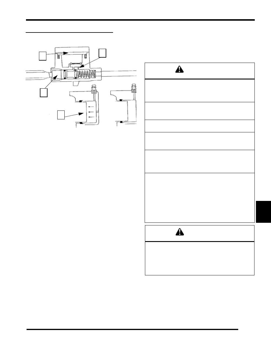
When the hand activated brake lever (A) is applied, it contacts
a piston (B) within the master cylinder. As the master cylinder
piston moves inward it closes a small opening called a
compensating port (C) within the cylinder and starts to build
pressure within the brake system. As the pressure within the
system is increased, the pistons (D) located in the brake caliper
move toward the disc and applies pressure to the moveable
brake pads. As the lever pressure is increased, the braking effect
is increased.

The friction applied to the brake pads will cause the pads to
wear. As the pads wear, the piston within the caliper self-adjusts
and moves further outward.

Brake fluid level is critical to proper system operation. A low
fluid level allows air to enter the system causing the brakes to
feel spongy.

Compensating Port

Located within the master cylinder is a small compensating port
(C) which is opened and closed by the master cylinder piston
assembly. The port is open when the brake lever is released and
the piston is outward. As the temperature within the hydraulic
system changes, this port compensates for fluid expansion
caused by heat, or contraction caused by cooling. During system
service, be sure this port is open. Due to the high temperatures
created within the system during heavy braking, it is very
important that the master cylinder reservoir have adequate space
to allow for the brake fluid to expand. Master cylinder reservoirs
should be filled to the top of the fluid level mark on the inside
of the reservoir, 1/4" - 5/16" (.6 -.8 cm) below lip of reservoir
opening.

This system also incorporates a diaphragm (E) as part of the
cover gasket and a vent port (on cover) located between the
gasket and the cover. The combination diaphragm and vent

allow for the air above the fluid to equalize pressure as the fluid
expands or contracts. Be sure the vent is open and allowed to
function. If the reservoir is overfilled or the diaphragm vent is
plugged, the expanding fluid may build pressure in the brake
system and lead to brake failure.

General Guidelines

Keep these points in mind when bleeding hydraulic brakes:

• The master cylinder reservoirs have limited capacities. 

It is easy to empty them during the bleeding procedure. 
This introduces air into the system which you are trying 
to purge. Watch the reservoir closely and add fluid 
when necessary to prevent air from entering the system.

• Apply only light to moderate pressure to the lever or 

pedal when bleeding the brake system. Extreme 

B

E

C

D

WARNING

Contaminated brake discs or brake pads greatly reduce 
braking performance and increase stopping distance. 
Do not attempt to clean contaminated pads. Replace 
them. Clean the brake disc with brake cleaner.

This brake system requires ethylene-glycol based fluid 
(DOT 4). Do not use or mix different types of fluid such 
as silicone-based or petroleum-based.

Do not use brake fluid taken from old, used or unsealed 
containers. Never reuse brake fluid. 

Keep brake fluid tightly sealed and out of reach of chil-
dren. Brake fluid can accumulate moisture, reducing it's 
effectiveness.

A soft, spongy feeling in the brake lever and/or brake 
pedal could indicate a hazardous condition in the brake 
system. Do not operate the motorcycle until the failure 
in the brake system is corrected.

An unsafe condition exists when air is trapped in the hy-
draulic brake system. Air in the brake hydraulic system 
acts like a soft spring and absorbs a large percentage 
of the pressure developed by the master cylinder. With-
out this pressure, the braking system cannot develop 
full braking force to allow for safe, controlled stops. It is 
extremely important to bleed the brakes properly after 
any brake system work has been performed or when in-
spection reveals spongy brakes.

CAUTION

Pressure bleeding is not recommended. When fluid 
surges through the fittings, it is possible to cavitate the 
fluid and create air in the system. In addition, the fluid 
stored in a pressure bleeder may be contaminated. Al-
ways use fresh DOT 4 brake fluid from a sealed con-
tainer.

7.20

FINAL DRIVE/BRAKES

pressure will cause a surge of fluid through the small orifices of the brake system when the bleeder screw is opened and 
introduce air into the system by means of cavitation.

• Small amounts of air can become trapped in the banjo bolt fittings at the master cylinder(s) and junction points of brake 

lines. These fittings can be purged of air by following a standard bleeding procedure at these fittings (instead of the bleed 
screw on caliper) if necessary to speed the bleeding process. This is usually only needed if system was completely drained 
of fluid. Bleed each line connection, starting with the fitting closest to the master cylinder, working toward the caliper, and 
ending with the bleed screw. 

• Always torque banjo bolts and other brake system fittings to specified torque.

• Change fluid every 2 years, or when fluid is dark or contamination is suspected.

Brake Fluid Replacement & Bleeding

This procedure should be used to change fluid or bleed brakes during regular maintenance, or after complete brake service. Brake
fluid may damage painted or plastic surfaces. Take care not to spill, and wipe up any spills immediately. Cover parts to avoid damage.

1.

Clean the reservoir cover.

2.

Remove the two T-15 Torx™ screws from the cover.

3.

Carefully remove the cover and diaphragm assembly from the reservoir.

4.

Under the cover, inspect the vent slots under the bellows and remove any debris or blockage.

5.

Bleed or replace the fluid by attaching a clear hose from the caliper bleeder fitting to a clean container. Be sure the hose fits
tightly on the bleeder fitting.

6.

Pump the brake lever a few times and hold.

7.

Slowly open the bleeder fitting and let the old fluid or air escape. You will feel the lever release as you let the fluid or air escape.

8.

Pump the brake lever a few times and hold it again.

7.21

FINAL DRIVE/BRAKES

7

9.

Repeat steps 7 and 8 until you see new brake fluid coming
from the caliper bleeder fitting or if you are bleeding the
air, repeat this step until you see only fluid coming out. This
may take several intervals.

10. Torque the bleeder screw to 8-11 ft-lb (11-15 N-m).

11. When adding fluid, add DOT 4 brake fluid to 1/4-5/16" (.6-

.8 cm) from the reservoir top.

12. Install cover and diaphragm assembly.

13. Tighten the cover screws to 16-20 in-lb (1.8-2.3 N-m).

14. Field test machine before putting into service. Check for

proper braking action and lever reserve. Lever reserve is
when the lever is firmly applied, the lever reserve should
be no less than 1/2" (1.3 cm) from the handlebar. 

15. Verify that the sight glass indicates a full reservoir. 

16. Check brake system for any fluid leaks.

Brake Line Replacement

Follow these steps if the brake line is to be replaced.

1.

If needed bleed the brake system by attaching a clear hose
to the caliper bleed fitting.

2.

Attach the other end to a Mity Vac or similar vacuum tool.

3.

Bleed the system of brake fluid.

4.

Note the orientation of the brake line. The brake line will
need to be replaced in the same orientation.

5.

Remove the brake line from the caliper. Cap or cover the
end to catch any brake fluid that may still be in the line.

6.

Loosen the brake line from the master cylinder 1/4 to 1/2
turn.

7.

Remove the 4 screws that hold the master cylinder to the
handlebar. This will separate the master cylinder from the
switch pack.

8.

Unplug the brake light switch harness from the master
cylinder.

9.

Remove the brake line from the master cylinder.

10. Install new brake line on caliper and orientate it as noted in

step 4.

T 

Bleeder Screw: 8-11 ft-lb (11-15 N-m)

T 

Cover Screws: 16-20 in-lb (1.8-2.3 N-m)

144-192 in-lb (16-22\N-m)

brake light switch

168-216in-lb (18.9-24.4 N-m)

7.22

FINAL DRIVE/BRAKES

11. Torque the caliper banjo bolt to 168-216 in-lb (19-24 N-m).

12. Insert the new brake line and install into the master

cylinder. Torque the brake line to 144-192 in-lb 
(16-21 N-m).

13. Tighten the brake line into the master cylinder in an

orientation so that the line does not have any sharp bends
when it is installed on the handlebar.

14. Route the brake light switch in the harness correctly.

15. Place the switch pack with the master cylinder onto the

handle bar. Two smaller screws should be placed on the top
and the longest screw is placed on the lower right.

16. Follow the bleeding procedure. See “Brake Fluid

Replacement & Bleeding” on page 7.20.

Brake Light Switch Replacement

1.

Remove the 4 screws that hold the master cylinder to the
handlebar. This will separate the master cylinder from the
switch pack.

2.

Unplug the brake light switch harness from the master
cylinder.

3.

Unplug the brake light switch from the master cylinder.

4.

Replace faulty brake light switch into the master cylinder
and route wires correctly.

5.

Plug the brake switch back into the harness.

6.

Replace the master cylinder to the switch pack and insert
the smaller screws on the top, the longest one goes into the
lower right side.

T 

Caliper Banjo Bolt: 168-216 in-lb (18-24 N-m)

T 

Brake Line: 144-192 in-lb (16-22 N-m)

500 INDY, 340 Classic, 550 Classic, 340 Touring, Trail Touring,Trail Touring Deluxe 


Content   ..  46  47  48  49   ..