Snowmobile Polaris EDGE / WIDETRAK (2007-2012 year). Instruction - part 35


  Index      Snowmobiles / ATV     LX Snowmobile Polaris EDGE / WIDETRAK - instruction 2007-2012 year


Search            copyright infringement  


Content   ..  33  34  35  36   ..


Snowmobile Polaris EDGE / WIDETRAK (2007-2012 year). Instruction - part 35


5.38

Engine Systems

9923396 - 2007-2012 EDGE/Widetrak LX Service Manual

©2011 Polaris Sales Inc.

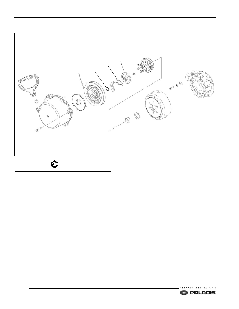
500EV Recoil / Magneto

Disassembly / Assembly Process

1.

Remove the exhaust pipe and resonator.

2.

If the recoil assembly does not require attention, the
recoil rope can remained attached to the handle. If
recoil component work is desired, reference the
Recoil Assembly section. See “Recoil Pulley” on
page 5.12.

3.

Remove the recoil / magneto housing cover. The
recoil assembly is located inside the housing.

4.

Remover the recoil hub from the flywheel. Secure the
flywheel with a strap wrench, PN PU-45419. Remove
the flywheel nut and washer.

5.

Using the flywheel puller tool, PN 2871043, insert the
puller’s three screws into the flywheel.

NOTE: Do not thread the puller screws into the
magneto/stator located behind the flywheel.

6.

Turn the puller center bolt in until the flywheel “pops”

off of the crankshaft.

7.

Mark the location of the magneto / stator plate in
several places using a scribe.

8.

Remove the magneto / stator from the crankcase.

9.

Clean the crankshaft and flywheel tapers with a
solvent such as clutch cleaner.

10. Assembly is reverse of disassembly. Reference the

fastener torque specifications at the beginning of the
chapter.

11. Do not use an impact wrench to install the flywheel

nut.

RECOIL HANDLE

ROPE GUIDE

RECOIL HOUSING

SPRING

ROPE REEL

RETURN SPRING

RATCHET

FRICTION SPRING

FRICTION PLATE

RECOIL HUB

FLYWHEEL NUT

FLYWHEEL

MAGNETO / STATOR

A

B

A

C

B

T 

A = 9 Ft.Lbs. (12 Nm)
B = 5 Ft.Lbs. (7 Nm) - Apply Loctite 242 (Stator)
C = 90 Ft.Lbs. (122 Nm) - Apply Loctite 242

5.39

Engine Systems

5

9923396 - 2007-2012 EDGE/Widetrak LX Service Manual

©2011 Polaris Sales Inc.

500EV Pistons / Crankshaft

Disassembly / Assembly Process

1.

To remove the pistons, follow the process for
removing the cylinder head and cylinders from the
engine.

2.

To remove the crankshaft, follow the process for
disassembling the crankcase assembly.

3.

With the piston out of the cylinder, remove one of the
c-clips and discard. Never re-use piston c-clips.

4.

Push the piston pin out of the piston and upper rod
bearings. Inspect the pin for galling and abnormal
wear. Inspect the needle bearing by feel and replace
as required.

5.

New pistons are supplied with new rings and a piston
pin. It is recommended that new needle bearings be
installed as well.

6.

When installing a new piston, insert one c-clip into the
piston making sure the open end is 180° opposite of

the groove opening.

7.

Apply a liberal amount of Polaris two-stroke engine oil
to the needle bearings, piston pin and piston
assembly.

8.

Push the pin in to the piston, then through the needle
bearing. Install the remaining c-clip with the open end
is 180° opposite of the groove opening.

NOTE:  Always use new cylinder base gaskets.

9.

Apply a liberal amount of Polaris two-stroke oil to the
cylinder wall. Align the piston ring gaps around the
piston locating pins. Compress the upper ring, then
carefully slide the cylinder down over the ring.

10. Compress the lower ring, then slide the cylinder down

over the ring.

PISTON

PISTON PIN

PISTON RINGS

C-CLIP

NEEDLE BEARINGS

PTO CRANKCASE SEAL

BEARINGS

BEARING

FLYWHEEL KEY

MAG CRANKCASE SEAL

Piston Matrix

Engine Model

Piston PN

Piston ID

S3033-5044-PF5F

2202318

EK-2252d

5.40

Engine Systems

9923396 - 2007-2012 EDGE/Widetrak LX Service Manual

©2011 Polaris Sales Inc.

500EV Crankcase

Disassembly / Assembly Process

1.

Remove the engine from the engine compartment. 

2.

Follow the process for removing the cylinder head,
cylinders, pistons, flywheel / recoil housing, and the
water / oil pump.

3.

Remove the intake boots, and reed assemblies.
Discard any seals or gaskets.

4.

Remove the crankcase fasteners then carefully pry
apart the crankcase halves. Discard the PTO and
MAG crankshaft seals.

5.

Clean the two crankcase mating surfaces with
carburetor cleaner and a gasket remover. Flush out
the crankcase.

6.

Reinstall the crankshaft back into the lower crankcase
using two new crankcase seals.

7.

Apply a thin bead of Three Bond 1215 to the lower
crankcase mating surface. Install the upper
crankcase.

8.

Loosely install the crankcase fasteners, then torque to
the specifications at the beginning of the chapter. Use
the correct torque sequence when tightening the
screws.

INTAKE BOOTS

REED STUFFERS

REED ASSEMBLIES

IMPULSE FITTING

OIL INJECTION CHECK VALVES

CRANKCASE

WATERPUMP BUSHING SCREW

DRAIN PLUGS

CYLINDER STUDS

A

B,C

T 

A = 9 Ft.Lbs. (12 Nm)
B = (M8) - 22 Ft.Lbs. (30 Nm) - Apply Loctite 242
C = (M6) - 9 Ft.Lbs. (12 Nm) - Apply Loctite 242

In. / mm. 

Long Studs Height (Exhaust side) = 3.66" (93mm)
Small Stud Height (Intake side) = 2.16" (55mm)

5.41

Engine Systems

5

9923396 - 2007-2012 EDGE/Widetrak LX Service Manual

©2011 Polaris Sales Inc.

500EV Water / Oil Pump

Disassembly / Assembly Process

IMPORTANT: Use the mechanical seal installation
tool to install the water pump seal, PN: 2872010.

1.

Remove the coolant from the engine using a siphon,
wet/dry vac. or a drain pan.

2.

Remove the airbox, exhaust pipe and resonator.
Remove the hose connected to the water pump cover.

3.

To access the impeller and mechanical seal, remove
the water pump cover. Discard the water pump cover
gasket.

4.

Remove the impeller nut, impeller and washers from
the cross shaft.

5.

Carefully pry the mechanical seal  and seal out of the

crankcase.

6.

Water pump assembly is the reverse of disassembly.
Always use new seals and gaskets during assembly.

7.

To remove the oil pump / cover, remove the two
fasteners then pull the pump / cover out of the
crankcase bore. Discard the gasket.

8.

The cross shaft can be extracted from the water pump
side of the crankcase.

9.

Assembly is the reverse of disassembly. Always use
new o-rings, seals and gaskets during assembly.

10. Install a new seal onto the shaft from the water pump

side.

11. To install a new water pump seal, use the seal

installation tool, PN 2872010. Verify the seal lips are
facing the cross shaft gear.

OIL PUMP

GASKET

BUSHING

O-RING

WASHER

CROSS SHAFT

WATER PUMP COVER

WATER PUMP COVER GASKET

NUT

WASHER

WASHER

MECHANICAL SEAL

SEAL

A

B

C

WASHER

T 

A = 7 Ft.Lbs. (9.5 Nm)
B = 10 Ft.Lbs. (13 Nm)
C = 9 Ft.Lbs. (12 Nm)


Content   ..  33  34  35  36   ..