Snowmobile Polaris EDGE / WIDETRAK (2007-2012 year). Instruction - part 18


  Index      Snowmobiles / ATV     LX Snowmobile Polaris EDGE / WIDETRAK - instruction 2007-2012 year


Search            copyright infringement  


Content   ..  16  17  18  19   ..


Snowmobile Polaris EDGE / WIDETRAK (2007-2012 year). Instruction - part 18


3.10

Maintenance

9923396 - 2007-2012 EDGE/Widetrak LX Service Manual

©2011 Polaris Sales Inc.

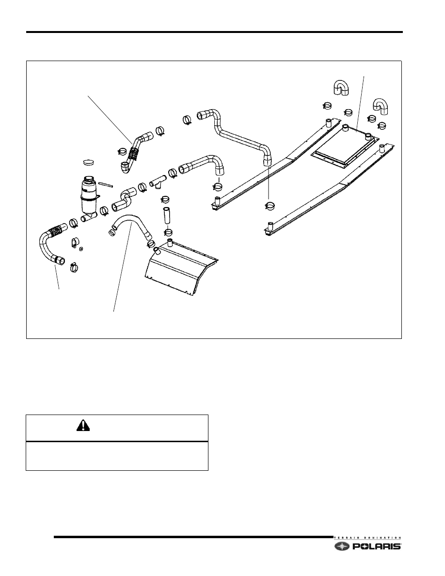
500 XCSP Cooling System

Surge Tank

Keep the level of the coolant inside the surge tank
between high and low marks. Coolant level will rise and fall
depending on the coolant temperature.

Always add coolant when the cooling system is COLD.

FRONT HEAT EXCHANGER

LEFT HEAT EXCHANGER

COOLANT HOSE

(FLOW = TO ENGINE)

BRAKE CALIPER

SURGE TANK

COOLANT HOSE
(FLOW = ENGINE OUT - THERMOSTAT OPEN)

RIGHT HEAT EXCHANGER

REAR HEAT EXCHANGER

COOLANT HOSE
(FLOW = ENGINE OUT - BYPASS CIRCUIT

CAUTION

Never remove the fill tube pressure cap when the cooling
system is warm. Severe burns to skin may occur from
escaping coolant or steam.

3.11

Maintenance

3

9923396 - 2007-2012 EDGE/Widetrak LX Service Manual

©2011 Polaris Sales Inc.

Recommended Coolant

Use Polaris Premium 60 / 40 pre-mix antifreeze. This
premium antifreeze is rated for temperatures down to -
62°F (-52°C). 

Cooling System Bleeding

1.

Allow the cooling system to cool completely.

2.

Verify the coolant level in the surge tank is at the
COLD mark.

3.

Remove the pressure cap and fill the fill cap with
coolant to the base of the pressure cap seat. Loosely
install the pressure cap.

4.

Elevate the front of the machine slightly.

5.

Apply the parking brake and start the engine.

6.

Allow the engine idle time to stabilize, then set the
RPM to approximately 600 RPM.

7.

Immediately add coolant to the fill tube if the coolant
level dropped significantly after the engine started.
Watch the level and add more coolant until the level
stops dropping.

8.

Secure the pressure cap with the vent lock open.

9.

Verify the tunnel coolers begin to warm up as the
engine continues to run.

10. Turn off the engine once the tunnel coolers are

sufficiently warmed-up. Close the vent lock on the
pressure cap. Release the parking brake.

11. Allow time for the coolant temperature to cool. Re-

check the coolant level in the surge tank. Add more
coolant if required.

12. Reset the engine idle RPM to specification.

Water Pump Drive Belt Tension

1.

Slightly loosen the water pump mounting fasteners.

2.

Pull the intake nozzle-side of the housing up to apply
tension to the belt.

3.

Secure mounting fasteners when belt deflection is 1/
8

 to 3/16

 (3 - 4mm).

Oil Pump Adjustment - 340 / 550 Engines

NOTE:  Before adjusting oil pump, always verify the
throttle lever free play and idle speed RPM are set to
specification.

1.

Verify the oil pump MAX OIL FLOW in line marker is
aligned with the oil pump body mark at WOT (Wide
Open Throttle).

2.

Lever adjustment is accomplished by loosening the
two oil pump cable jam nuts, then moving the
threaded barrel up or down until the two marker lines
are aligned at WOT.

3.

Apply Loctite 262 to barrel threads and secure jam
nuts when adjustment is set.

Oil Pump Adjustment - 488 LC Engine

NOTE:  Before adjusting oil pump, always verify the
throttle lever free play and idle speed RPM are set to
specification.

1.

Verify the oil pump lever in line marker is aligned with
the oil pump body mark at the exact point when the
carburetor slides begin to move when the throttle lever
is pressed.

3.12

Maintenance

9923396 - 2007-2012 EDGE/Widetrak LX Service Manual

©2011 Polaris Sales Inc.

2.

Lever adjustment is accomplished by loosening the
two oil pump cable jam nuts, then moving the
threaded barrel up or down until the two marker lines
are aligned at the exact point when the throttle slides
begin to move.

3.

Apply Loctite 262 to barrel threads and secure jam
nuts when adjustment is set.

Oil Pump Adjustment - 500 XCSP

NOTE:  Before adjusting oil pump, always verify the
throttle lever free play and idle speed RPM are set to
specification.

1.

Always verify the throttle cable free play is set to
specification (.010

 - .030

).

NOTE: The oil pump lever arm line mark MUST be
aligned with the oil pump boss index mark at the exact
moment when the throttle slides begin to lift from the
idle position.

2.

Remove the air box from the engine compartment.

3.

Locate the oil pump under the carburetor rack.

4.

If necessary, use a mirror or a bore scope and a light,
to visually inspect the current oil pump setting.

5.

Verify the lever mark is inline with the oil pump boss
index mark at the exact moment when the throttle
slides begin to lift from the idle position.

6.

If the oil pump lever requires adjustment or the cable
is going to be replaced, loosen the two jam nuts using
a 10mm wrench.

7.

When adjusting the lever, make adjustments in small
increments, then re-check the timing mark alignment.

8.

After setting the oil pump lever correctly, apply a small
drop of Loctite 242 to the cable barrel threads, then
secure the jam nuts.

9.

Re-check the oil pump alignment marks after securing
the jam nuts to verify the marks are set correctly.

10. Re-assemble the removed components in the reverse

they were removed. Reference the appropriate
service manual chapter for component assembly
fastener torques.

Oil Pump Bleeding

1.

Verify oil tank is filled with oil.

2.

Loosen the bleed screw (A). Verify a stream of oil
flows from the bleed screw.

3.

After bleeding oil pump, secure bleed screw and wipe
up oil residue.

NOTE:  Any time that the engine is disassembled or
repaired, it is important to purge air within the hoses
and oil pump.

Oil Pump Bleeding - 550 Engines

1.

On 550cc engines that do not feature the oil pump
bleed hose between the oil pump and oil tank, place
some clean shop towels around the oil pump. Start the
engine, then pull the oil pump lever to the full-open
position for 30 seconds.

2.

Verify a stream of oil flows from the bleed screw.

3.

Turn off the engine, then secure the bleed screw.

4.

After bleeding oil pump, secure bleed screw and wipe
up oil residue.

NOTE:  Any time that the engine is disassembled or
repaired, it is important to purge air within the hoses
and oil pump.

CAUTION

The oil pump lever and pump boss marks must be 

observed straight-on to yield accurate results.

BLEED SCREW

LEVER MARK

BOSS INDEX MARK

A

3.13

Maintenance

3

9923396 - 2007-2012 EDGE/Widetrak LX Service Manual

©2011 Polaris Sales Inc.

Oil Pump Bleeding - 550 Engines with Auto 

Bleed

1.

Large pockets of air can be purged from the oil hoses
by using a Mity Vac hand pump if desired.

NOTE: THE ENGINE WILL STILL RECEIVE THE
REQUIRED AMOUNT OF OIL WHILE RUNNING EVEN
WITH AIR TRAPPED IN THE SUPPLY HOSE.
FOLLOWING PROCEDURE SHOWN ON A 550 IQ OIL
TANK. PROCESS IS THE SAME ON EDGE OIL TANKS.

2.

Remove the auto-bleed hose from the oil storage
tank. Connect a Mity Vac hand pump to the storage
tank fitting.

3.

Place the end of the auto-bleed hose into a small cup
or container. Pressurize the storage tank with the
hand pump until oil begins to flow from the auto-bleed
hose.

4.

To stop the flow of oil, loosen the oil tank cap.

5.

Reinstall the auto-bleed hose on the tank fitting.

6.

Pour the oil in the container into the storage tank.

Oil / Fuel Filter

• EDGE Models - The oil filter on EDGE models is 

incorporated within the oil level sender unit. Filter 
replacement requires sender replacement.

• Widetrak Models - The oil filter on Widetrak 

models is an in-line type. The arrow on the filter 
body indicates the oil flow.

All models feature a fuel pickup a with filter located inside
the fuel tank. To inspect and replace:

1.

Remove the gas cap.

2.

Use a coat hanger to carefully pickup the fuel hose
inside the tank.

3.

Inspect and replace the pickup/filter at the end of the
hose.

CAUTION

The in tank fuel filter and fuel lines should be inspected 

regularly. Special attention should be given to the fuel 

line condition after periods of storage. 

Normal deterioration from weather and fuel can occur 

during this storage period. Do not damage fuel lines 

when removing them. If a fuel line has been damaged or 

kinked it must be replaced.


Content   ..  16  17  18  19   ..