Snowmobile Polaris (2006 year). Instruction - part 70
13.22
ELECTRICAL
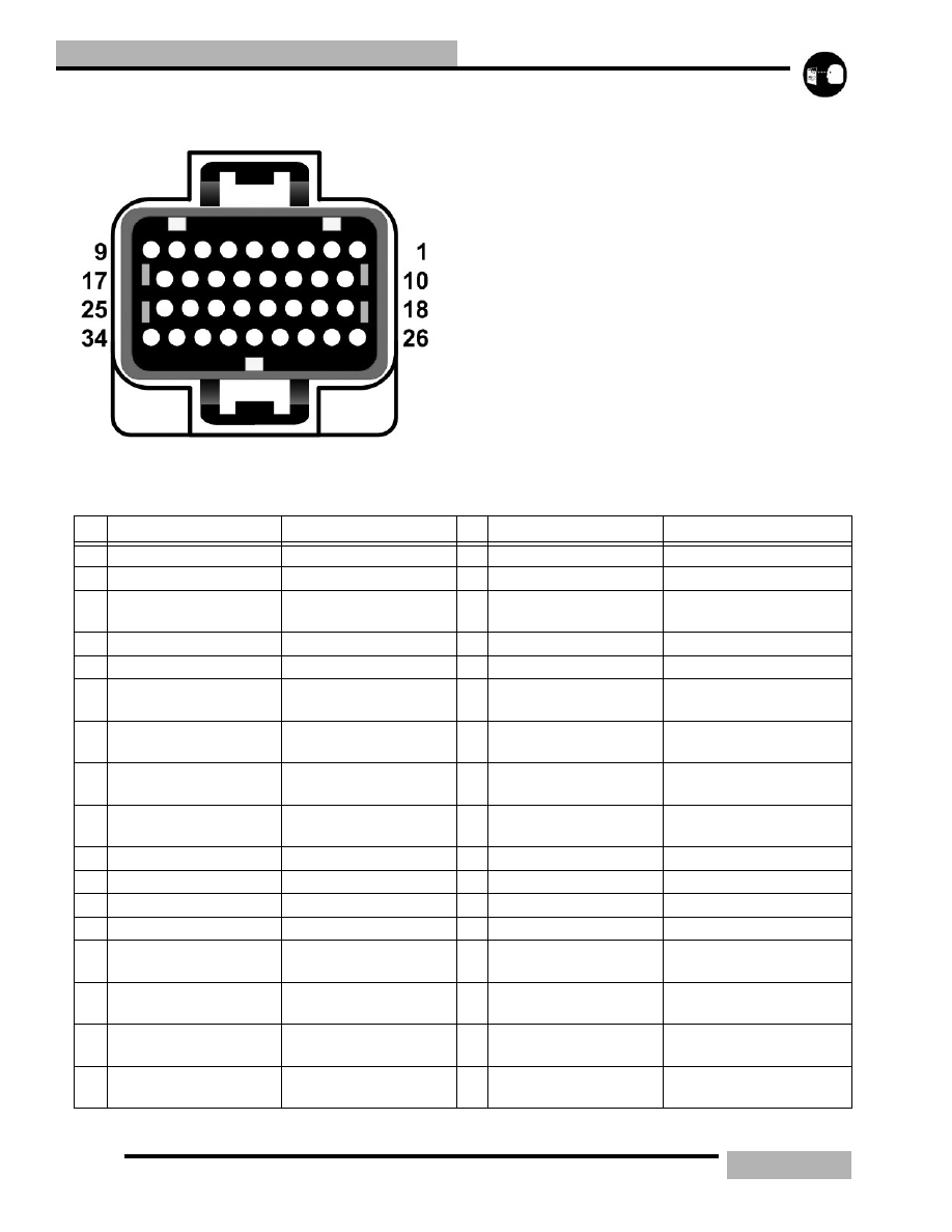
ECU PLUG #1
As viewed unplugged
Table 13-16:
PIN
WIRE COLOR
COMPONTENT
PIN
WIRE COLOR
COMPONENT
1
Orange
Reg Rec (power)
18 Orange
Reg Rec (power)
2
-
-
19 Red/Black
External Battery Voltage
3
-
-
20 Black/Blue
Exhaust/Air Temp sensor
(ground)
4
Yellow/Red
Tachometer (signal)
21 Black
Auxilary Kill Switch
5
Blue/Red
Water temp (signal)
22 Black/Red
software kill
6
Green
PTO Injector full load
(ground)
23 Blue
Air Temp
7
Green/White
PTO Injector part load
(ground)
24 White/Black
Exhaust temp sensor
8
Yellow
MAG Injector full load
(ground)
25 Green/Blue
EV Solenoid (ground)
9
Yellow/White
MAG Injector part load
(ground)
26 Red
Voltage Reg (power)
10 Orange
Reg Rec (power)
27 -
-
11 White/Blue
Chassis Relay Coil
28 Brown
Ground (ECU)
12 -
-
29 Black/White
Dianostic LED
13 Gray
Reverse Switch
30 Green/Blue
Hot lamp
14 Red/Blue
PTO Injector full load
(power)
31 White
Reverse lamp
15 Red/Blue
PTO Injector part load
(power)
32 -
-
16 Red/Blue
MAG Injector full load
(power)
33 Orange/Green
Battery Relay Coil
17 Red/Blue
MAG Injector part load
(power)
34 -
-