Suzki Burgman AN400. Manual - part 22
ENGINE 3-51
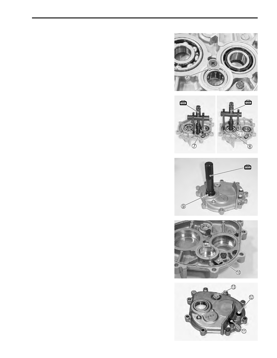
• Remove the bearing retainer
6
.
• Remove the bearings
7
,
8
using the special tool.
%
09921-20240: Bearing remover set(
7
20 mm)
(
8
25 mm)
• Remove the bearing
9
using the special tool.
%
09913-70210: Bearing installer set (32 × 35 mm)
• Remove the magnet
0
.
• Clean the magnet with a cleaning solvent.
• Remove the drain plug
A
, oil level plug
B
and oil filler plug
C
.