Suzki Burgman AN400. Manual - part 15
ENGINE 3-23
ENGINE COMPONENT INSPECTION AND
SERVICE
CYLINDER HEAD COVER
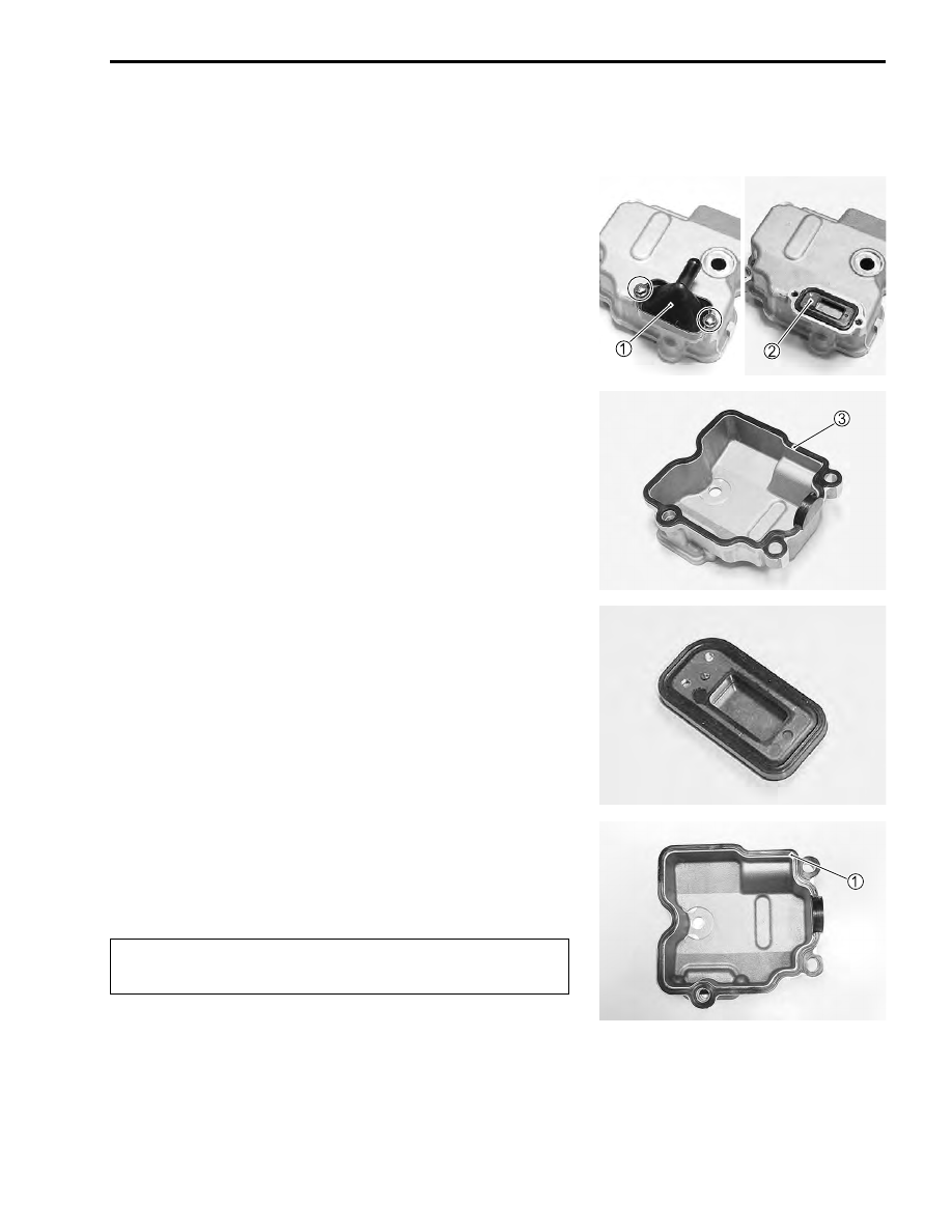
DISASSEMBLY
• Remove the PAIR reed valve cover
1
and PAIR reed valve
2
.
• Remove the cylinder head cover gasket
3
.
INSPECTION
• Inspect the reed valve for the carbon deposit.
• If the carbon deposit is found in the reed valve, replace the
PAIR reed valve with a new one.
REASSEMBLY
• Reassembly the cylinder head cover in the reverse order of
disassembly. Pay attention to the following points:
• Install the cylinder head cover gasket
1
.
$
Replace the removed cylinder head cover gasket with
a new one.