Suzki Burgman AN400. Manual - part 7
2-18 PERIODIC MAINTENANCE
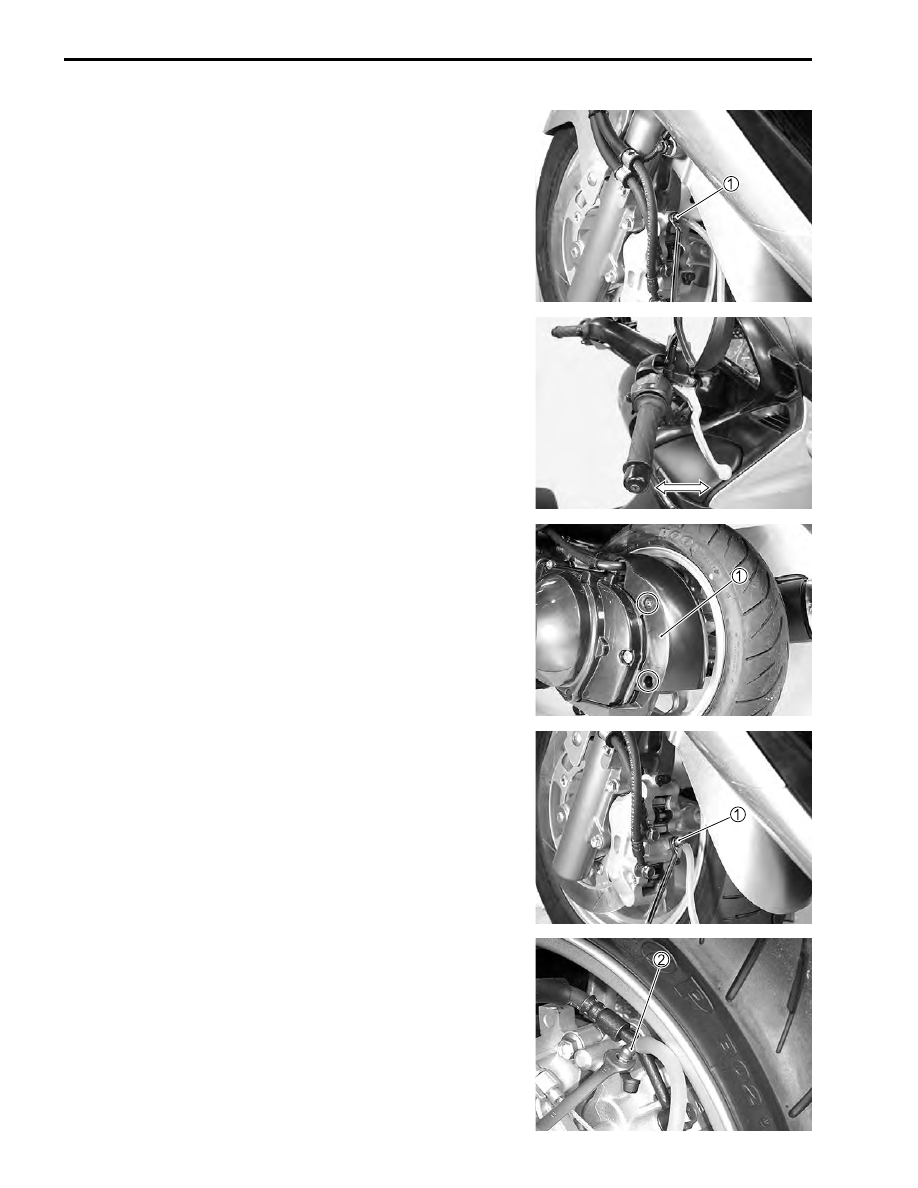
• Connect a clear hose
1
to the air bleeder valve and insert the
other end of the hose into a receptacle.
• Loosen the air bleeder valve and pump the brake lever until
the old brake fluid is completely out of the brake system.
• Close the air bleeder valve and disconnect the clear hose. Fill
the reservoir with new brake fluid to the upper end of the
inspection window.
#
Air bleeder valve: 7.5 N·m (0.75 kgf-m, 5.5 lb-ft)
COMBINATION BRAKE FLUID REPLACEMENT
• Place the motorcycle on a level surface and keep the handle-
bar straight.
• Remove the rear brake caliper cover
1
.
• Remove the master cylinder reservoir cap and diaphragm.
• Suck up the old brake fluid as much as possible.
• Fill the reservoir with new brake fluid.
)
Specification and classification: DOT4
• Connect a clear hose
1
to the air bleeder valve and insert the
other end of the hose into a receptacle.
• Loosen the air bleeder valve and pump the brake lever until
the old brake fluid is completely out of the brake system.
• Close the air bleeder valve and disconnect the clear hose. Fill
the reservoir with new brake fluid to the upper end of the
inspection window.
• Next, connect a clear hose
2
to the air bleeder valve on the
rear brake caliper. The rear brake fluid replacement is the
same way as that of the front one.