Airbus A319/A320/A321. Flightdeck and systems briefingfor pilots (1998)

AIRBUS
A319/A320/A321
Flightdeck and systems
briefingfor pilots
THIS BROCHURE IS PROVIDED
FOR INFORMATION PURPOSES ONLY
AND ITS CONTENTS
WILL NOT BE UPDATED.
IT MUST NOT BE USED AS AN OFFICIAL REFERENCE.
FOR TECHNICAL DATA OR OPERATIONAL PROCEDURES,
PLEASE REFER TO THE
RELEVANT AIRBUS DOCUMENTATION
STL 945.7136/97
Issue September 1998

Contents
1. General
2. Flight deck layout
3. Electrical system
4. Hydraulic system
5. Flight controls
6. Landing gear
7. Fuel system
8. Engine controls
9. Auxiliary power unit
10. Automatic flight system
11. Environmental flight system
12. Electronic instrument system
13. Radio management and communication
14. Maintenance centralized fault display system
STL 945.7136/97
1

1. General
STL 945.7136/97
1.1
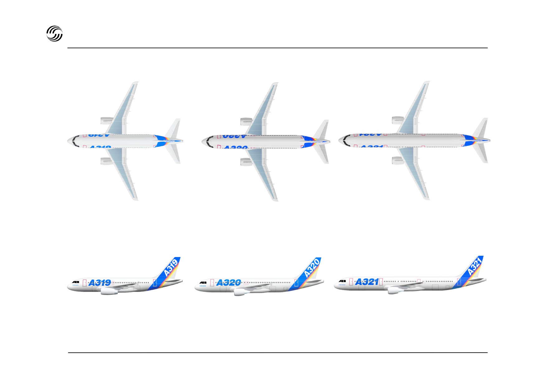
A319/A320/A321 General
A319
A320
A321
STL 945.7136/97
1.2
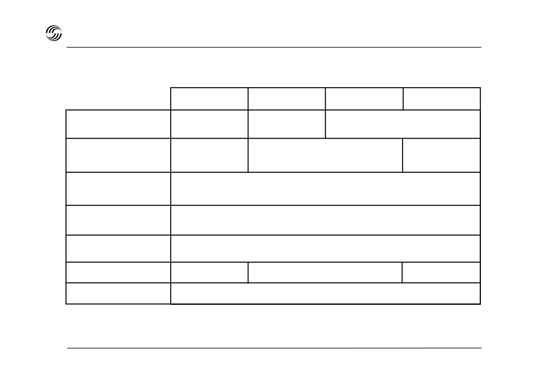
A319/A320/A321 general
A319-100
A320-100
A320-200
A321-100
Span
34.10m
33.91m
34.10m
111ft 10in
111ft 3in
111ft 10in
Length
33.84m
37.57m
44.51m
111ft
123ft 3in
146ft
11.76m
Height
38ft 7in
Fuselage
3.95m
Diameter
12ft 11in
7.59m
Track
24ft 11in
Max. pax
145
180
220
Max. FL
390
STL 945.7136/97
1.3
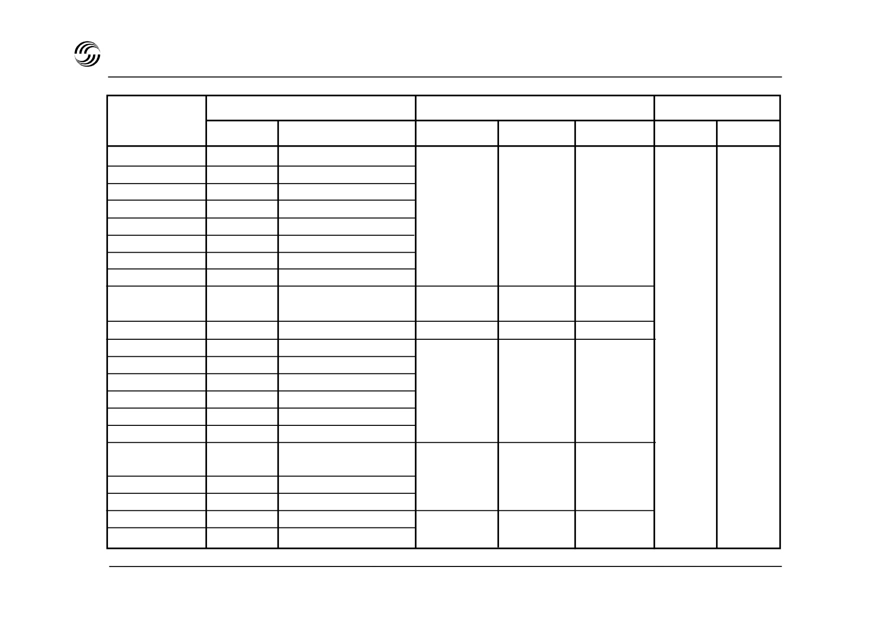
A319/A320/A3210general
Engine
Maximum weights (kg)
Operation limits
Model
Manuf.
Type
MTOW
MLW
MZFW
Mmo
Vmo
A319-111
CFM
CFM56-5B5
A319-112
CFM
CFM56-5B6
A319-113
CFM
CFM565A4
A319-114
CFM
CFM56-5A5
64 000
61
000
57 000
A319-115
CFM
CFM56-5B7
(options :
A319-131
IAE
V2522-A5
68 000 or
A319-132
IAE
V2524-A5
70 000)
A319-133
IAE
V2527-M-A5
A319
CFM
CFM56-5-B6/5B7
Corporate Jet
IAE
V2524-A5/V2527-M-A5
75 500
62
500
58 000
A320-111
CFM
CFM56-5-A1
68 000
63
000
59 000
0.82
350kt
A320-211
CFM
CFM56-5A1/5A3
A320-212
CFM
CFM56-5A3
73 500
64
500
60 500
A320-214
CFM
CFM56-5B4
(options : from
(option :
A320-231
IAE
V2500-A1
68 000 up to
61 000)
A320-232
IAE
V2527-A5
77 000)
A320-233
IAE
V2527E-A5
83 000
A321-111
CFM
CFM56-5B1
(options :
73
500
69 500
A321-112
CFM
CFM56-5B2
78 000 or
(option :
(option :
A321-131
IAE
V2530-A5
85 000)
74 500)
70 500
A321-211
CFM
CFM56-5B3
A321-231
IAE
V2533-A5
89 000
75 000
71 500
STL 945.7136/97
1.4

A319/A320/A321 introduction
The A319/A320/A321 are narrow body, twin-engined,
Introduced for airline service in March 1988, the A320
short
/ medium-range aircraft, the A319
being the
represents the largest single advance in civil aircraft
shortened version of the A320, and the A321 being the
technology since the introduction of the jet engine and
stretched version of the A320.
results in a major stride forward in airline profitability.
They both offer an increased fuselage cross-section
A computer-managed system gives complete
leading to an increased revenue potential through :
protection against excursions outside the normal flight
envelope and greatly improves the man / machine
- greater passenger comfort with wider seats and
interface.
aisle
- greater overhead baggage volume
- greater cargo capacity
- wide-body compatible container capability
- quicker turnrounds.
Advanced technology applied to aerodynamics,
structure, systems and powerplant offer reduced costs
through :
- unmatched fuel efficiency
- more accurate flight path control
- reduced maintenance costs
- increased reliability
- reduced trouble-shooting time.
STL 945.7136/97
1.5

2. A319/A320/A321flight deck layout
STL 945.7136/97
2.1

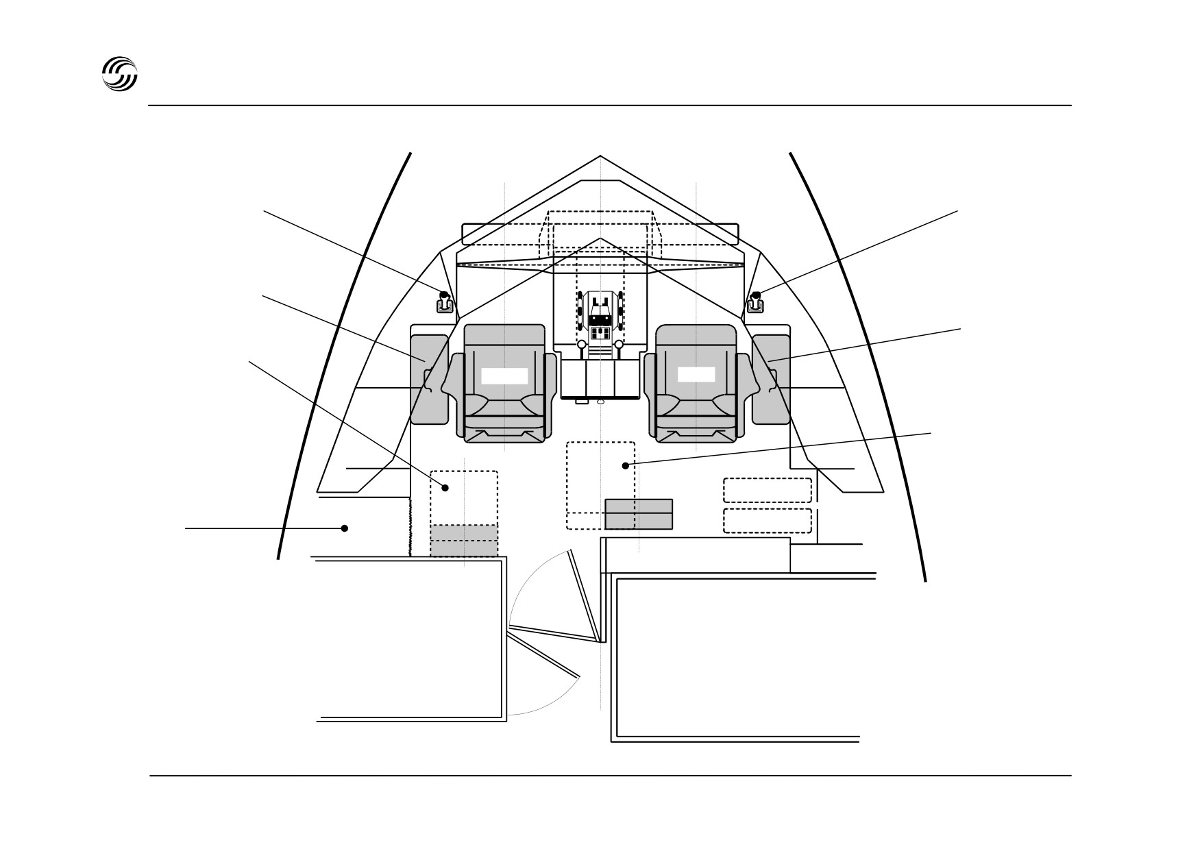
A319/A320/A321 flight deck - plan view
Capt. sidestick
F / O sidestick
Capt. nav. bag
F / O nav. bag
4th occupant
seat (optional)
CAPT
F/O
3rd occupant seat
Coat
stowage
z An observer seat aft of the pedestal offers maximum
visibility over all panels.
zAfourthoccupantseatsisofferedasanoption.
STL 945.7136/97
2.3

A319/A320/A321 flight deck - general arrangement
Foward view
Ceiling light
Reading light
Sun visor
F / O boomset stowage
Assist handle
Rope stowage
F / O boomset jack panel
Air conditioning outlet
Cup holder
Roller sunblind
Window control handle
Miscellaneous stowage
Sidestick
Flash light
Waste stowage
Briefcase
Hand microphone
Air conditioning outlet
lighting
Ashtray
Nosewheel
steering ctl
Operational manual
Briefcase
stowage
Check list stowage
Portable fire extinguisher
F / O quick donning oxygen mask
Flight documents stowage
3rd occupant quick donning oxygen mask
STL 945.7136/97
2.4
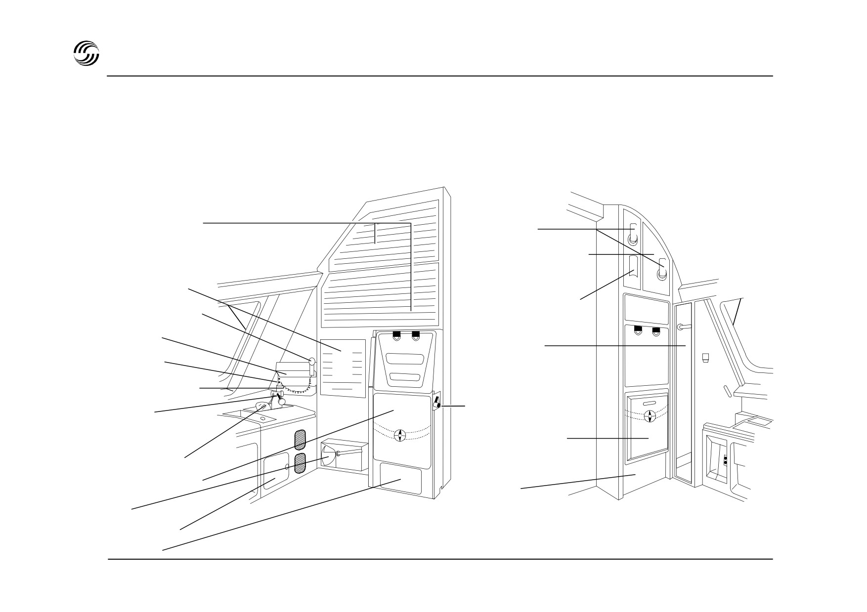
A319/A320/A321 flight deck - general arrangement
Rear view
Right corner
Left corner
Secondary
Hat stowage
circuit breakers
Bulbs, fuses stowage
Primary
circuit breakers
Rain repellant bottle
Hand microphone
Hat holder
Coat stowage
Jack panel
Headset stowage
Portable
Seat unlock
oxygen bottle
4th occupant seat
(optional)
Full face mask
3rd occupant seat
Life vest
Axe
Safety locker
Life vest
STL 945.7136/97
2.5
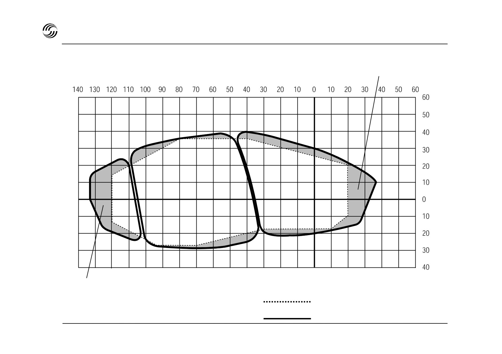
A319/A320/A321 flight deck - pilot’s field of view
Improved pilot vision
Pilot
Wing tip
axis
visible
Aerospace standard 580 B
A319/A320/A321
STL 945.7136/97
2.6

A319/A320/A321 flight deck - pilot’s field of view
Visibility
z Windows are designed to meet or exceed the
Aerospace standard 580 B.
Geometry :
- windshield panels
:
flat glass
- lateral windows
:
curved acrylic.
z Clear surface of each window :
Windshield panel
0.52m2 each
Lateral sliding window
0.36m2 each
Lateral rear window
0.30m2 each
Flight deck total
2.36m2
z This geometry improves external aircraft monitoring,
thereby increasing safety standards :
- downward visibility in the pilot axis is 20°
- wing tips visible from respective pilot stations.
STL 945.7136/97
2.7
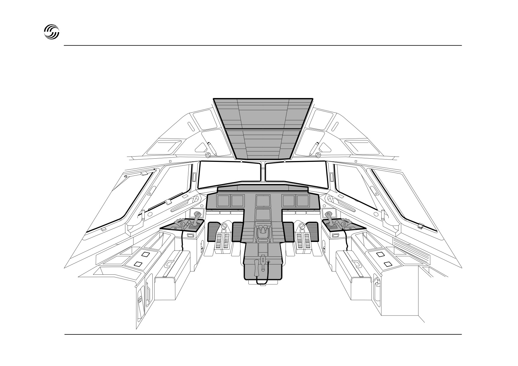
A319/A320/A321 flight deck - main features
Control and indication panels in bold outline
STL 945.7136/97
2.8

A319/A320/A321 flight deck - main features
z The main features :
- sidestick controllers which leave the main
instrument panel unobstructed
- six display units (DU) interchangeable, switchable
and integrated into the same system architecture
(EFIS / ECAM)
z The other features evolve directly from the concepts
introduced with the A300 / A310 family :
- ergonomic layout of panels, synoptically arranged
according to frequency of use (normal, abnormal,
emergency) within easy reach and visibility for
both crewmembers
- philosophy of panels (e.g., “lights out” philosophy
for overhead panel)
- principles of presentation on information (“need to
know” concept)
- monitoring of systems through an Electronic
Centralized Aircraft Monitor (ECAM)
- coherent system of colour coding for EFIS, ECAM
and panel lights.
STL 945.7136/97
2.9
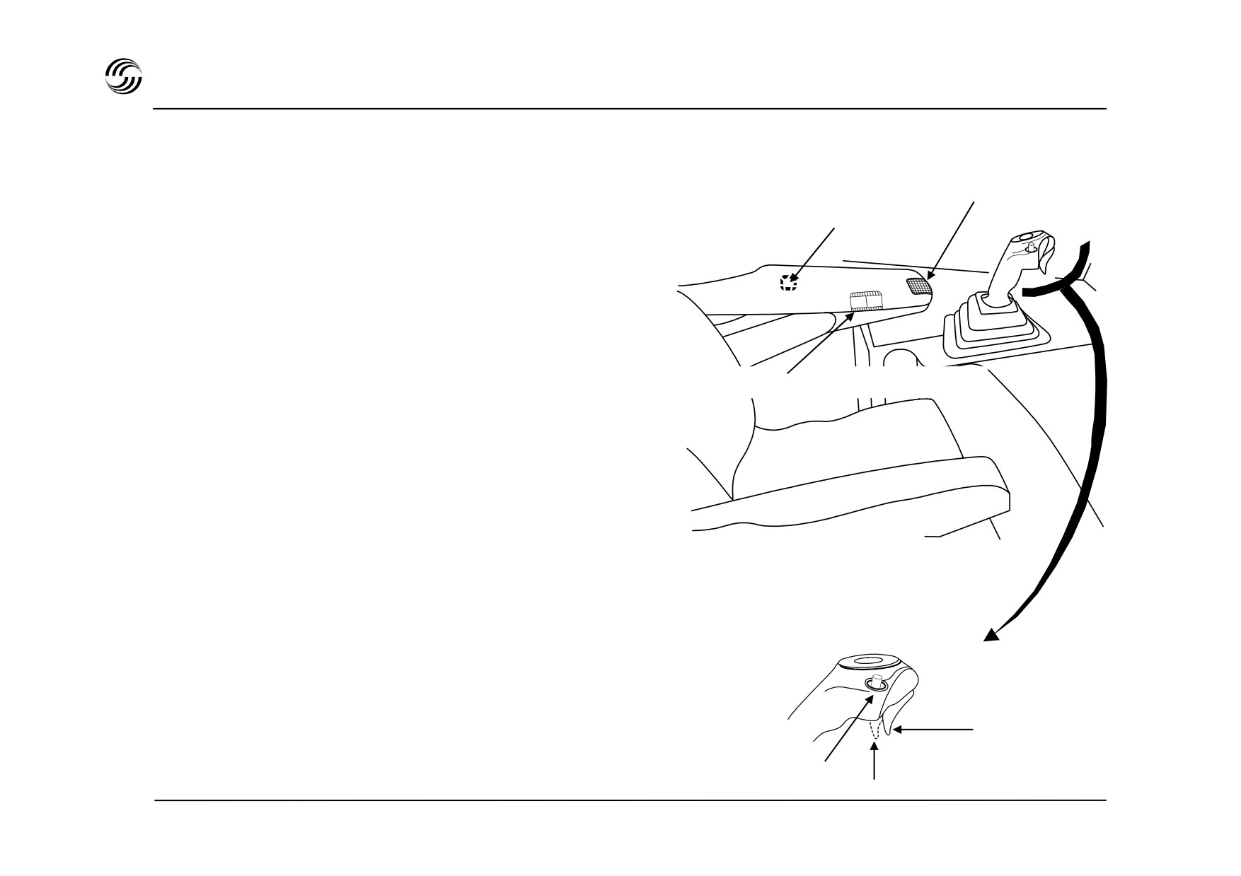
A319/A320/A321 flight deck - sidestick arrangement
Pitch control
z Sidesticks are installed on the CAPT and F
/ O
Height adjustment
forward lateral consoles.
z An adjustable armrest to facilitate free wrist
movement is fitted on each seat.
z The sidestick works against a spring force
proportional to the angular displacement.
Armrest memory position display
z Sidestick includes :
- radio communication trigger
- a take-over button for autopilot disconnection and
priority take-over.
Neutral
Take-over button
Radio
STL 945.7136/97
2.10
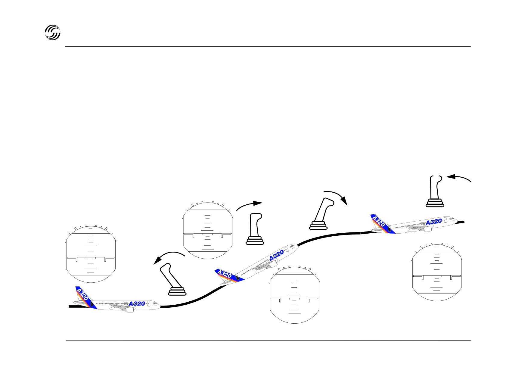
A319/A320/A321 flight deck - sidestick operation
z Moving the sidestick results in “setting the aircraft
trajectory” with a certain level of “g” for the requested
manoeuvre depending on the amount of sidestick
movement.
z Movement is very precise since back lash and friction
are negligible.
z Control of the flight path is performed by the
Electronic Flight Control System (EFCS) which links
the trajectory order with aerodynamic
data to
Sidestick released :
stabilize the aircraft and protect it from prohibited
return to neutral
attitudes.
Sidestick released : Sidestick pushed
return to neutral
10
10
10
10
10
10
10
10
10
10
10
10
10
10
10
10
STL 945.7136/97
2.11
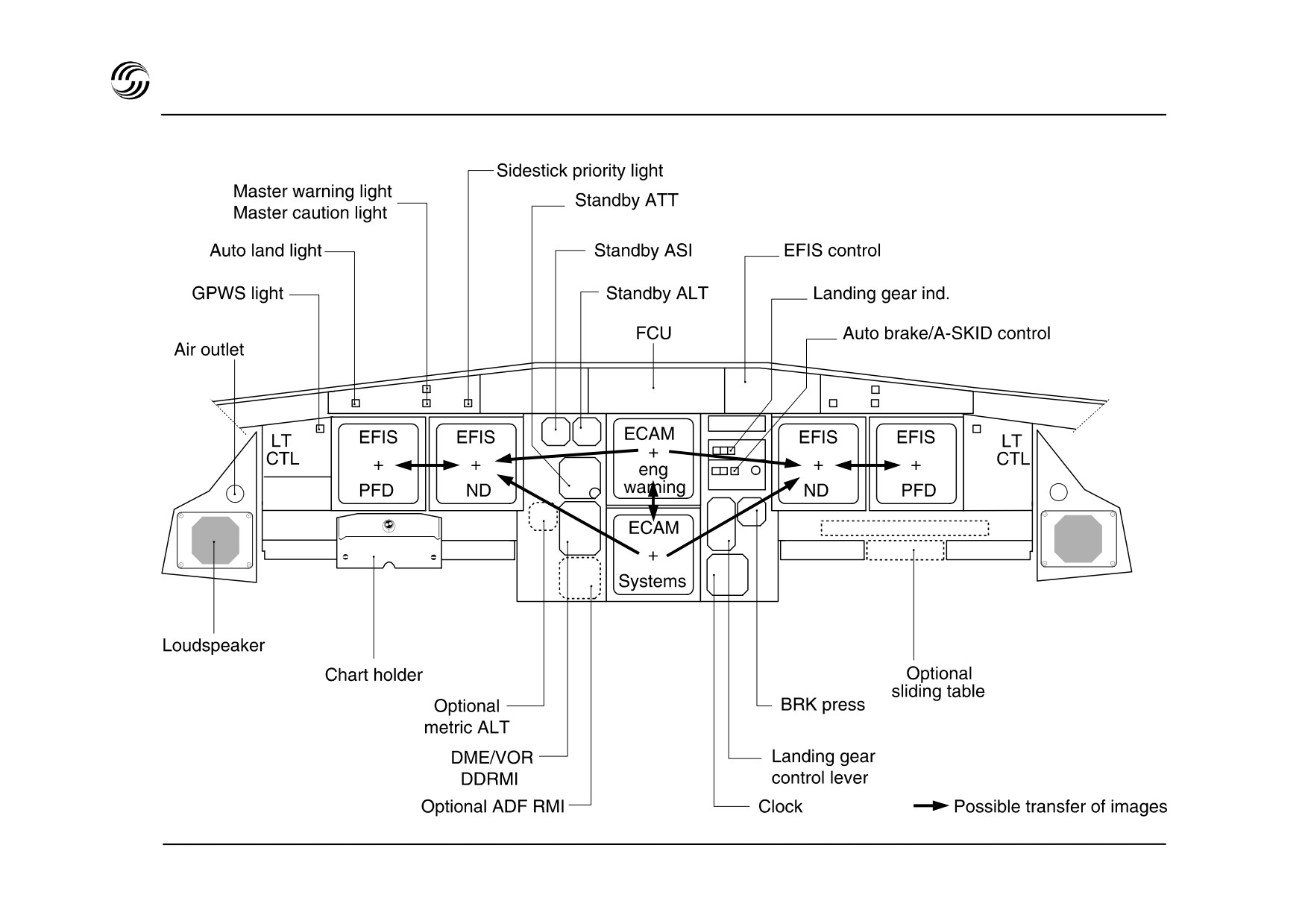
A319/A320/A321 flight deck - main instruments panels
STL 945.7136/97
2.12

A319/A320/A321 flight deck - CAPT and F/O panels
z
The CAPT and F / O panels are mirror image of each
z Navigation display offers three modes :
other
; both incorporate two side-by-side Display
Units (DU’s) (7.25in x 7.25in) :
-
ROSE mode (ILS, VOR or NAV): heading up,
aircraft symbol in screen centre, with radar
- a Primary Flight Display (PFD)
available,
- a Navigation Display (ND).
-
ARC mode : heading up, horizon limited to a 90°
forward sector, with radar available,
z
This arrangement facilitates :
-
PLAN mode : north up, display centered on
selected waypoint.
- a better visibility on all Dus in normal configuration
and in case of reconfiguration (PFD ND or ECAM
Note : In ROSE-NAV, ARC, and PLAN modes, MAP
ND)
data from FMS is presented.
- The possibility to install a sliding table (option) and
a footrest in front of each pilot.
z
Primary flight display includes the complete Basic
T with :
- attitude
- airspeed / Mach (with all upper ad lower limits)
- altitude / vertical speed
- heading
- AFS status
- ILS deviation / maker
- radio altitude
STL 945.7136/97
2.13
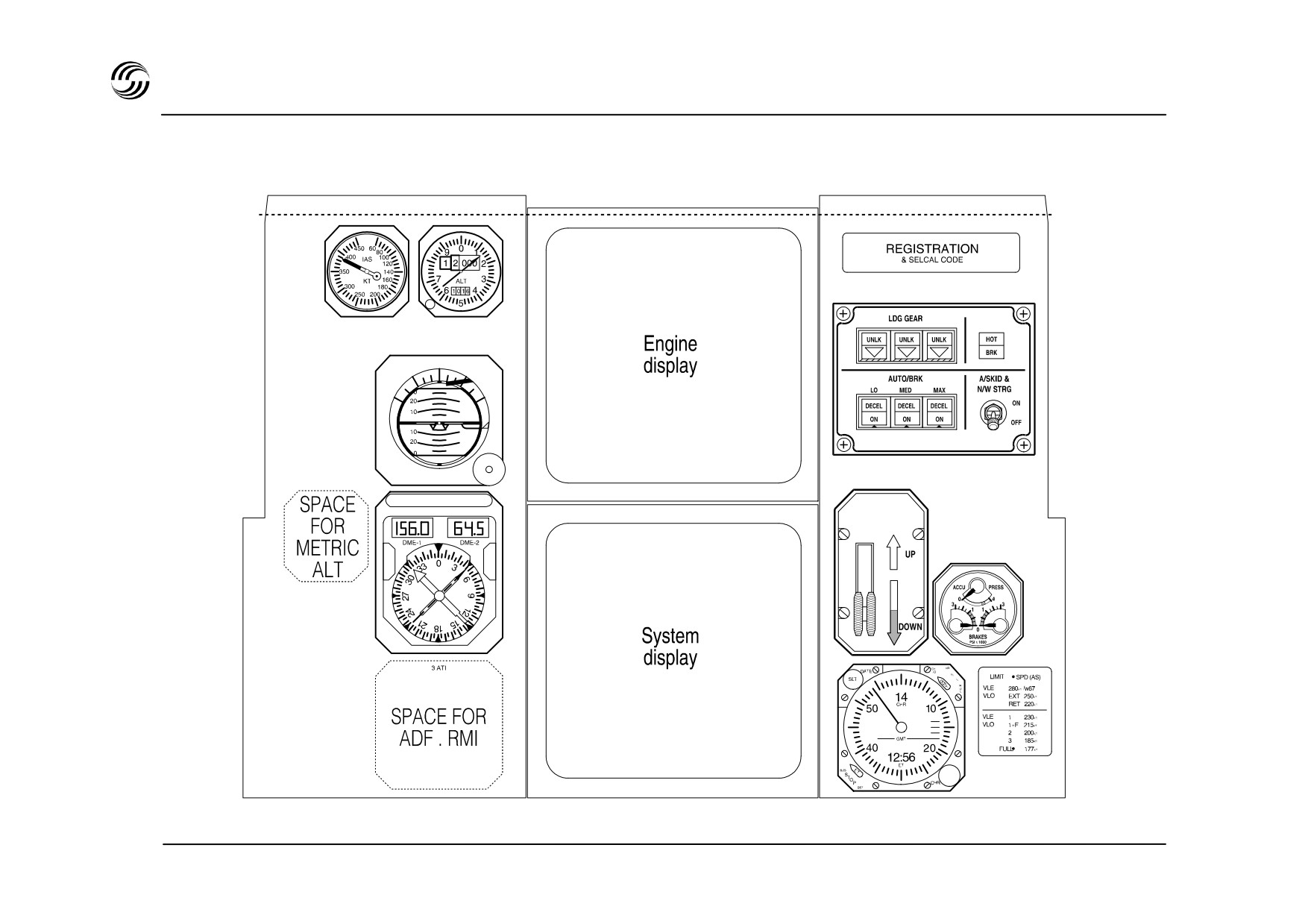
A319/A320/A321 flight deck - centre panel
STL 945.7136/97
2.14

A319/A320/A321 flight deck - centre panel
The centre panel groups :
- two Dus, one above the other, same size and
interchangeable with the CAPT and F / O Dus :
z Engine Display (DU 1), showing :
- the main engine parameters : N1, EGT; N2 (CFM)
or EPR, EGT, N1, N2 (IAE)
- thrust limit and command
- total fuel
- the flaps and slats position
- memo and warning.
z System Display (DU 2) showing :
- presentation of system synoptic diagrams
- status of the aircraft (list of all operationally
significant items)
- standby instruments
- landing gear control and indications (including
brakes)
- clock
STL 945.7136/97
2.15
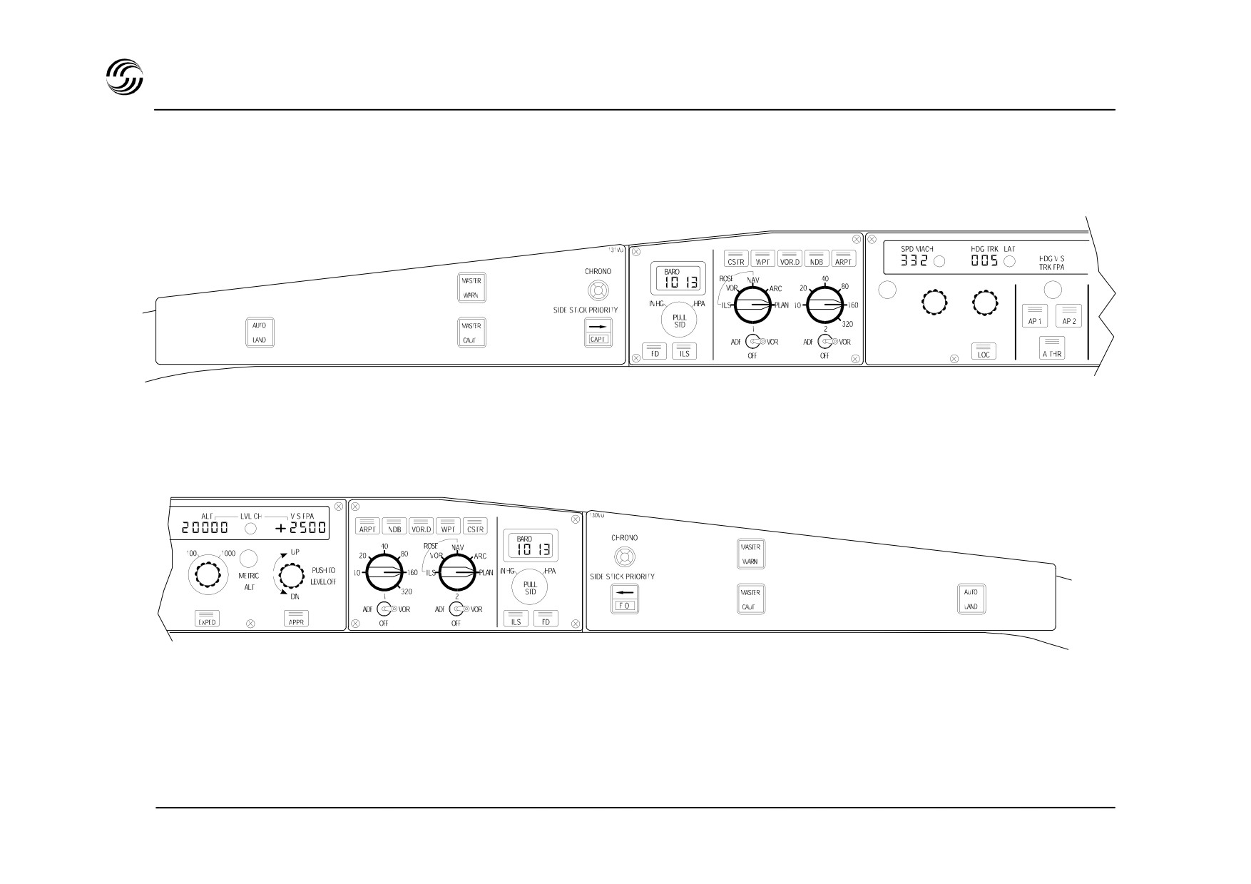
A319/A320/A321 flight deck - glareshield
STL 945.7136/97
2.16

A319/A320/A321 flight deck - glareshield
z The Flight Control Unit
(FCU) provides short-term
interface between the FMGC and crew for :
- engagement of A / P, FD, ATHR
- selection of required guidance modes
- manual selection of flight parameters SPD, MACH,
ALT, VSPD, HDG or track.
z The EFIS control panels for :
- selection of desired ND modes (ROSE-ILS, -VOR,
ARC, PLAN) and ranges,
- selection of baro setting.
z The master warning, master caution, autoland and
sidestick priority lights.
STL 945.7136/97
2.17
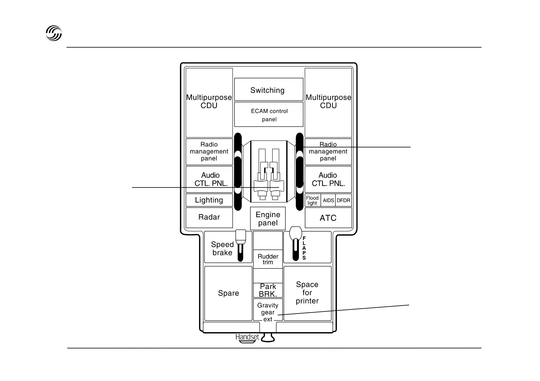
A319/A320/A321 flight deck - pedestal
Pitch trim wheel
Thrust and thrust
reverse control levers
Landing gear
gravity
extension handle
STL 945.7136/97
2.18

A319/A320/A321 flight deck - pedestal
In addition to the thrust levers and the engine control
functions, the main features on the pedestal are :
z The Multipurpose Control and Display Units (MCDU)
for flight management functions and various other
functions such as data link, maintenance etc…
z The Radio Management Panel (RMP) for tuning of :
all radio communications and the radio navigation as
a back-up to the normal operation through the Flight
Management and Guidance Computers (FMGC).
z The electrical rudder trim.
z A handle at the rear of the pedestal enables the
gravity landing gear function, to be operated easily
and rapidly.
STL 945.7136/97
2.19
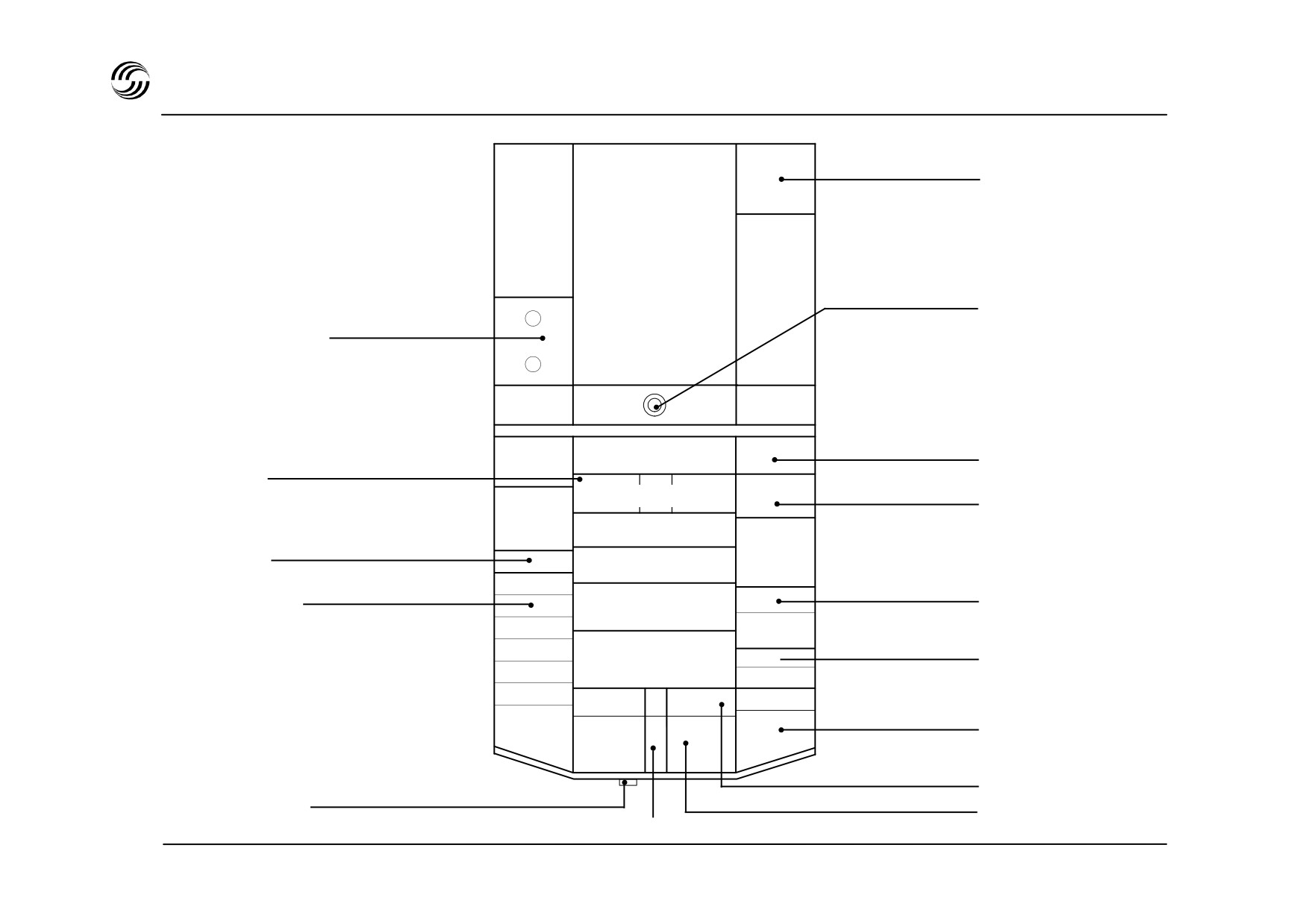
A319/A320/A321 flight deck - overhead panel
Maintenance panel
Spare
Circuit
breakers
Spare
Pedestal light
3rd and 4th occupant
air outlets
FMS
Spare
load
Spare
3rd audio control
Fire controls
Eng 1 APU Eng
2
3rd RMP (option)
ADIRS
CP
Hydraulics
Spare
Flight control
Fuel
EVAC
Flight control
Standby electrics
Electrics
Cargo
GPWS
heat
Options
RCDR
Air cond.
Cargo smoke
Oxygen
Vent
Calls
Anti-ice
Engine
Wiper
Wiper
EXT LT
Cabin pressure
CVR microphone
Internal lights and signs
APU control
STL 945.7136/97
2.20

A319/A320/A321 flight deck - overhead panel
z The overhead panel is “single slope” and one inch
higher than on previous Airbus aircraft.
z All controls on the overhead panel can be reached by
either pilot.
z Two main zones are separated by protective padding :
- Forward zone :
- for most frequently used functions at the front of
the panel
- for system controls : arranged in three main
rows :
center row for engine related systems
•
arranged in a logical way
lateral rows for other systems
•
- Aft zone, not used in flight, mainly :
- for circuit breakers corresponding to essential
systems necessitating segregation
- for a small maintenance panel corresponding to
some systems not linked to the Centralized
Fault and Display System (CFDS).
z The push-button philosophy is identical to that
already applied on existing Airbus aircraft.
STL 945.7136/97
2.21


3. Electricalsystem
STL 945.7136/97
3.1
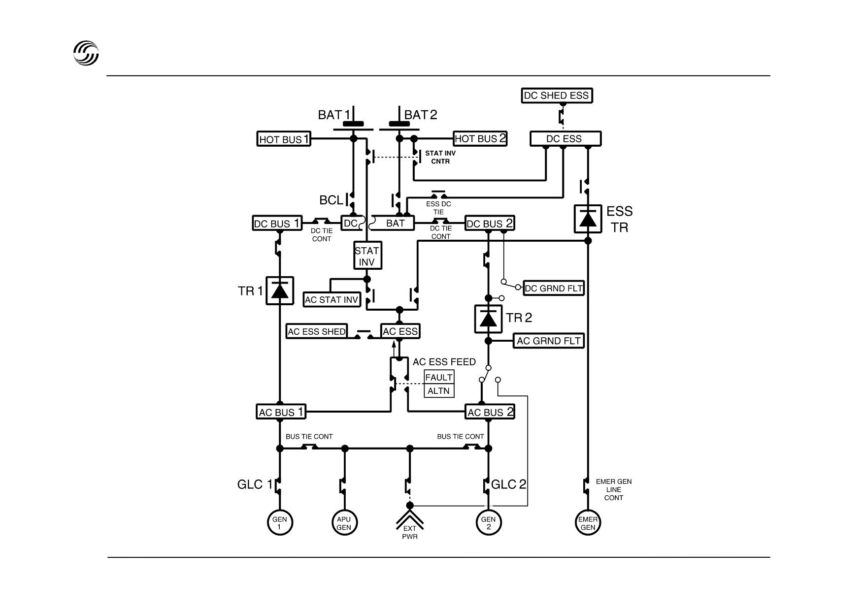
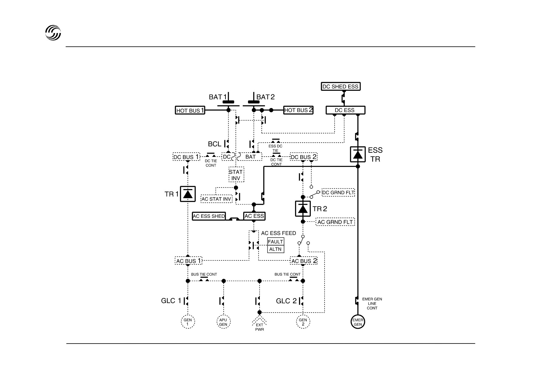
A319/A320/A321 electrical system architecture
STL 945.7136/97
3.2

A319/A320/A321 electrical system architecture
The electrical power generation comprises :
z Two batteries, nominal capacity 23Ah each
z Two engine-driven AC generators, nominal power
- on ground : to provide an autonomous source
90kVA
mainly for APU starting
- in emergency configuration to feed some
z One auxiliary power unit
(APU) AC generator
equipment :
nominal power 90kVA
•
during RAT deployment
•
after landing gear extension (only for A320).
z One emergency generator nominal power 5kVA,
hydraulically driven by the Ram Air Turbine (RAT),
automatically deployed in case of main generators
loss
z One ground connector, power 90kVA.
z DC network supplied via three identical Transformer /
Rectifier Units (TRU) :
- two of them are normally used
- the third is used :
in emergency configuration (loss of main AC
•
generators)
•
in case of TR 1 or TR 2 failure
STL 945.7136/97
3.3
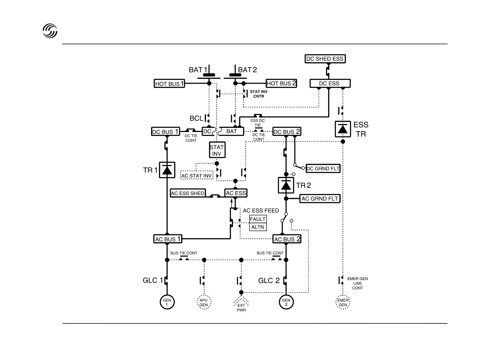
A319/A320/A321 normal electrical flight configuration
STL 945.7136/97
3.4

A319/A320/A321 normal electrical flight configuration
z In normal configuration, both normal AC systems are
split
z Each engine-driven generator supplies its associated
AC BUS via its Generator Line Contactor (GLC).
z AC ESS BUS is normally supplied from AC BUS via a
contactor.
z DC BAT BUS and the DC ESS BUS are normally
powered by the TR 1.
z Two batteries are connected to the DC BAT BUS via
the Battery Charge Limiter (BCL).
z Each battery has its own HOT BUS bar (engine / APU
firesquib, ADIRS, CIDS, ELAC
1, SEC
1, slide
warnings, parking brake etc).
STL 945.7136/97
3.5
A319/A320/A321 normal electrical flight configuration
Loss of main electrical generators - EMER GEN running
STL 945.7136/97
3.6

A319/A320/A321 normal electrical flight configuration
z In case of failure, the failed generator is automatically
replaced by :
- the APU generator if available
- the other main generator with automatic partial
galley load shedding.
z In case of total loss of all main generators, the RAT is
automatically extended and drives the emergency
generator via a hydraulic motor.
The EMER GEN supplies the AC ESS BUS and the
DC ESS BUS via the ESS TR.
The ECAM WD remains powered, with associated
procedures presented.
Alternate law is operative through ELAC 1 and SEC 1.
STL 945.7136/97
3.7

A319/A320/A321 electrical - control and display
Control panel
Batteries indication
System display :
Buses indication
Transformer / Rectifier
ELEC system page
Normal configuration
Generator indication
Integrate Drive
Generator indications
STL 945.7136/97
3.8
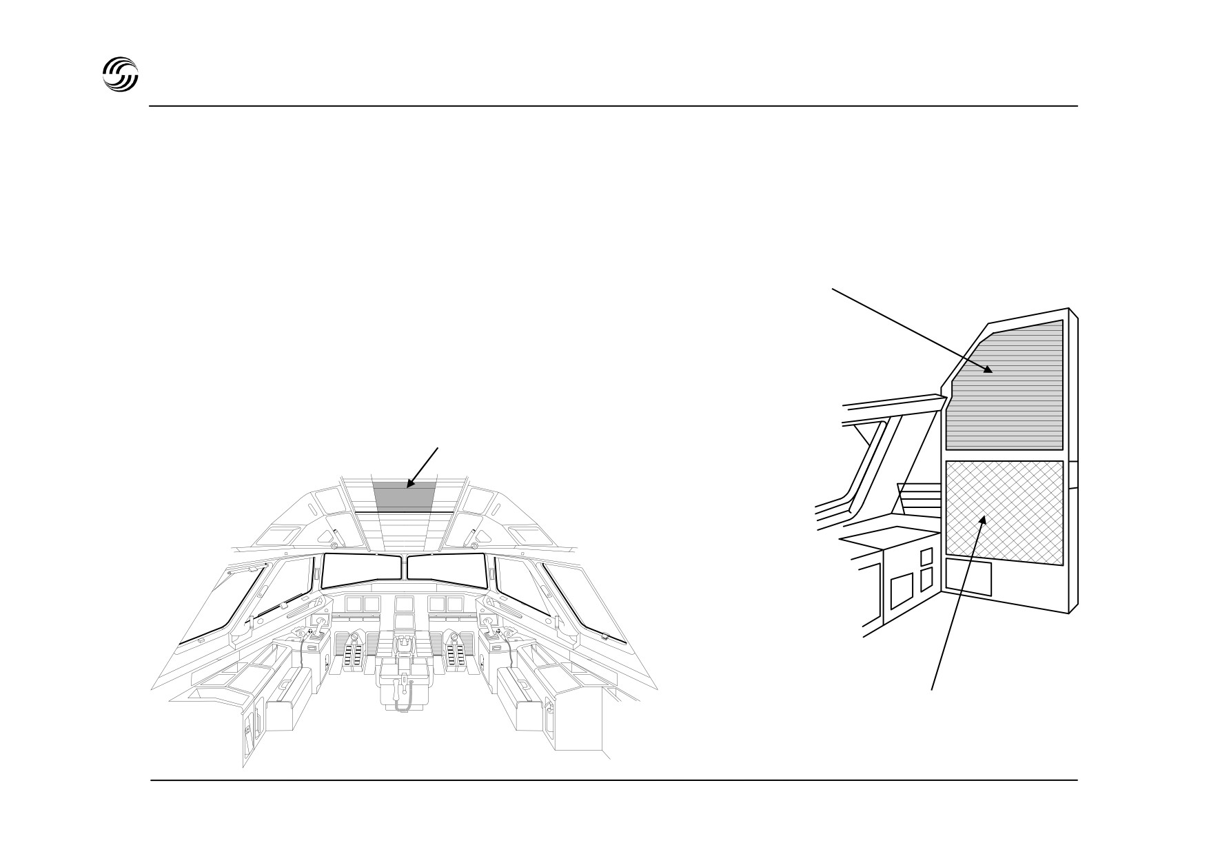
A319/A320/A321 cockpit circuit - breakers
z Circuit breakers (C / Bs) are constantly monitored and the
tripping of a C / B will be clearly indicated :
Rear right panel
either through
- activation of a system warning
- a failure test
- an abnormal instrument configuration
Secondary circuit breakers
(aircraft systems)
or, for C / Bs monitored by the ECAM system :
- six zones have been defined
- each time a C
/ B trips, the corresponding zone is
identified
Overhead panel
Emergency circuit breaker
Primary circuit breakers
(electrical generation)
STL 945.7136/97
3.9


4. Hydraulic system
STL 945.7136/97
4.1
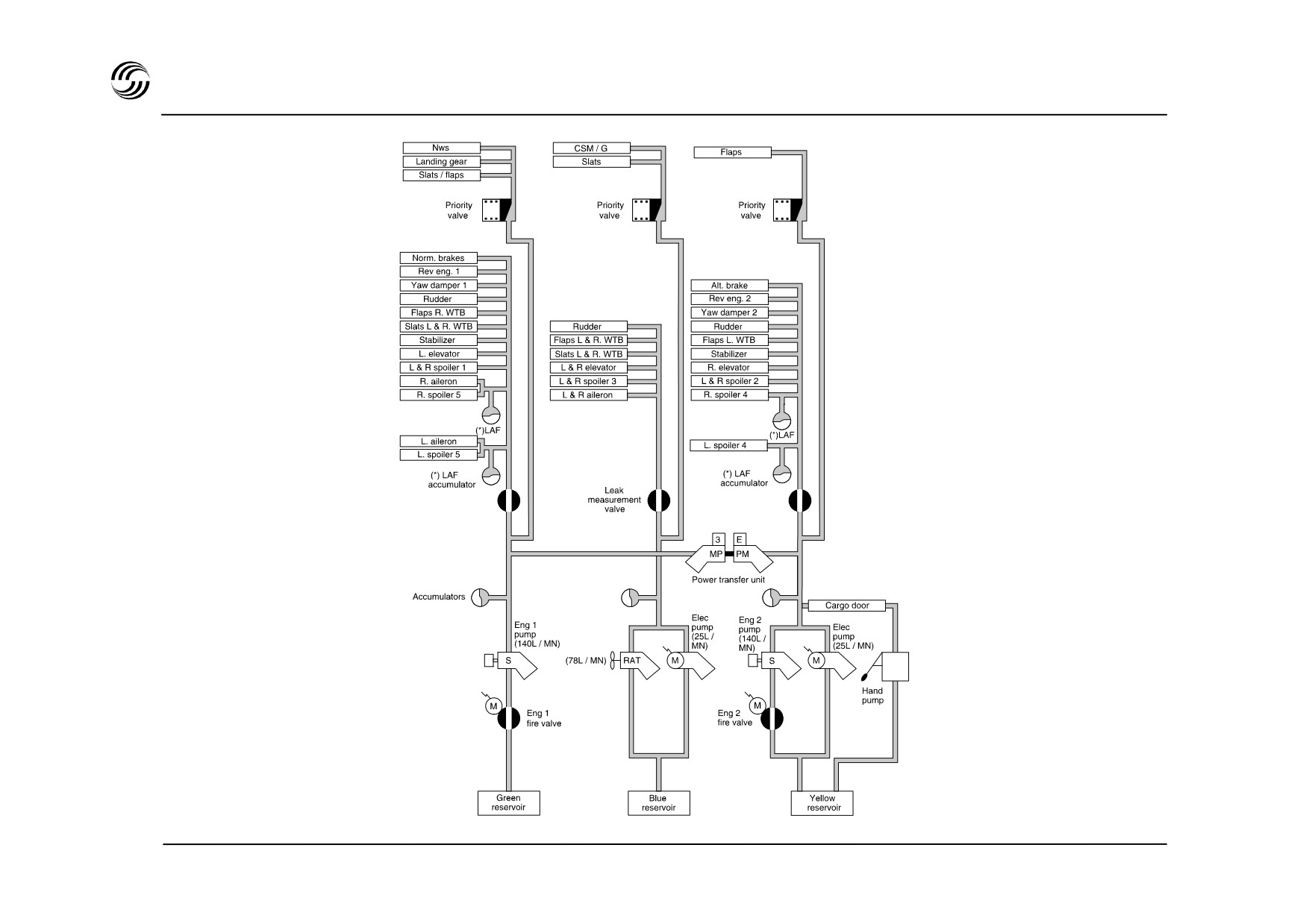
A319/A320/A321 hydraulic system architecture
(*) only for A320
STL 945.7136/97
4.2

A319/A320/A321 hydraulic system - general
z
Three fully independent systems : Green, Yellow,
z
On ground :
Blue.
-
Blue and Yellow systems may be pressurized by
z
Normal operation :
electric pumps.
A handpump (operated from the ground on the
- two engine-driven pumps (one each - Green and
yellow system) facilitates manoeuvring of the cargo
Yellow systems)
doors.
- one electric pump (Blue system)
-
Green/Yellow system may be pressurized by the
PTU.
z
Abnormal operation :
- if engine No. 1 inoperative or Green pump failed :
then Green system pressurized by the reversible
Power Transfer Unit (PTU)
- if engine No. 2 inoperative or Yellow pump failed :
then Yellow system pressurized by the reversible
PTU
- if Yellow system pump inoperative and PTU failed :
then an electric pump will pressurize the Yellow
system.
- if case of dual engine failure or total electrical
power loss :
the Ram Air Turbine (RAT) will pressurize the Blue
system.
STL 945.7136/97
4.3

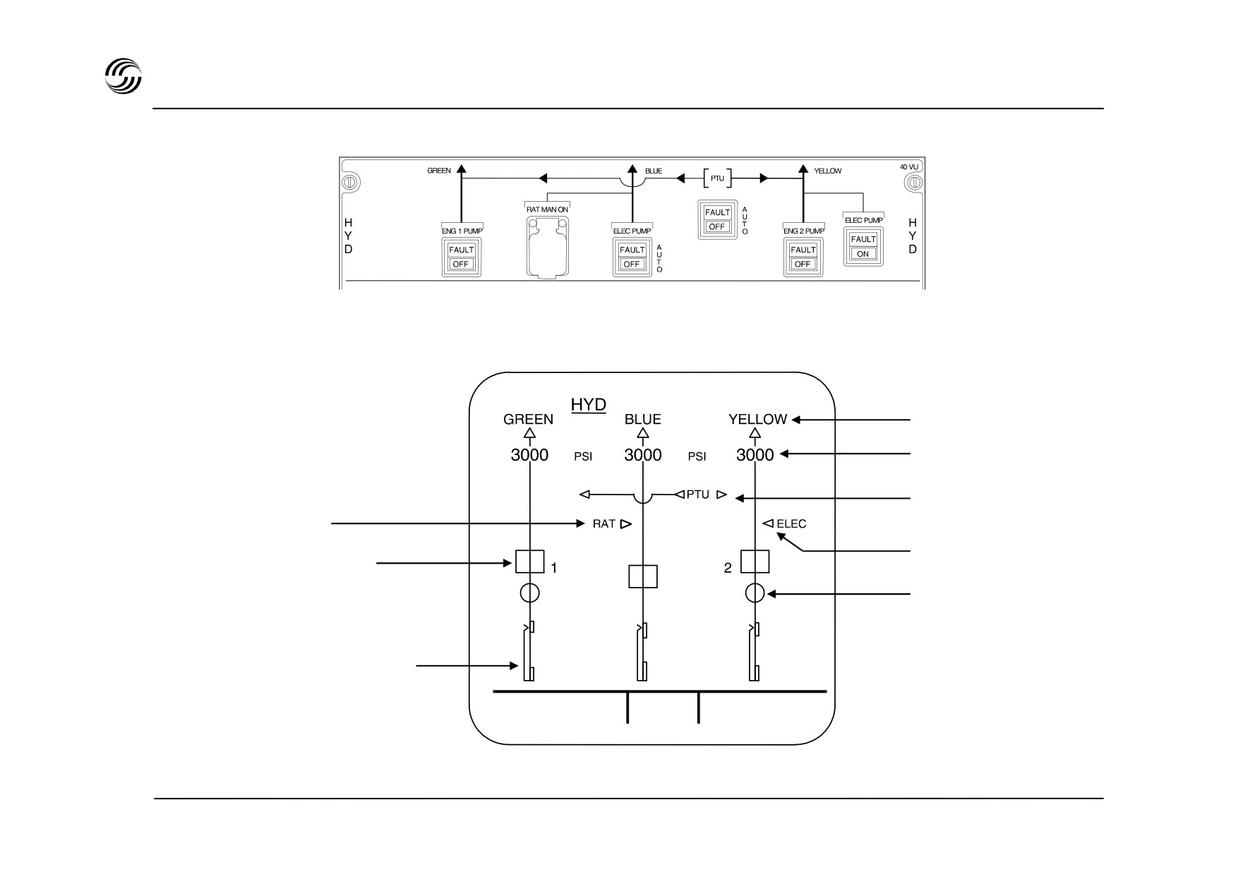
A319/A320/A321 hydraulic - control and display
Control panel
System display :
System label
System pressure
HYD system page
Power Transfer Unit
RAT
Yellow electrical pump
Engine pump
Fire valve position
Reservoir
quantity indication
TAT + 19 °C
G.W. 60300kg
SAT + 18 °C
23 H 56
STL 945.7136/97
4.5


5. Flightcontrols
STL 945.7136/97
5.1


A319/A320/A321 EFCS advantages
The Electrical Flight Control System (EFCS) provides :
z Safety improvements (stall
/ windshear / overstress
/
overspeed protection)
z Economical aspects
- weight saving =
W > 200kg considering the impact
on AFS
A319/A320/A321 plus same weight
gain on wing structure due to
integration of load alleviation function
function (A320 only).
- maintenance costs decreased
- training costs decreased
- production costs decreased
z Improvements in handling and comfort
- flight handling improvement
- new cockpit concept
STL 945.7136/97
5.3
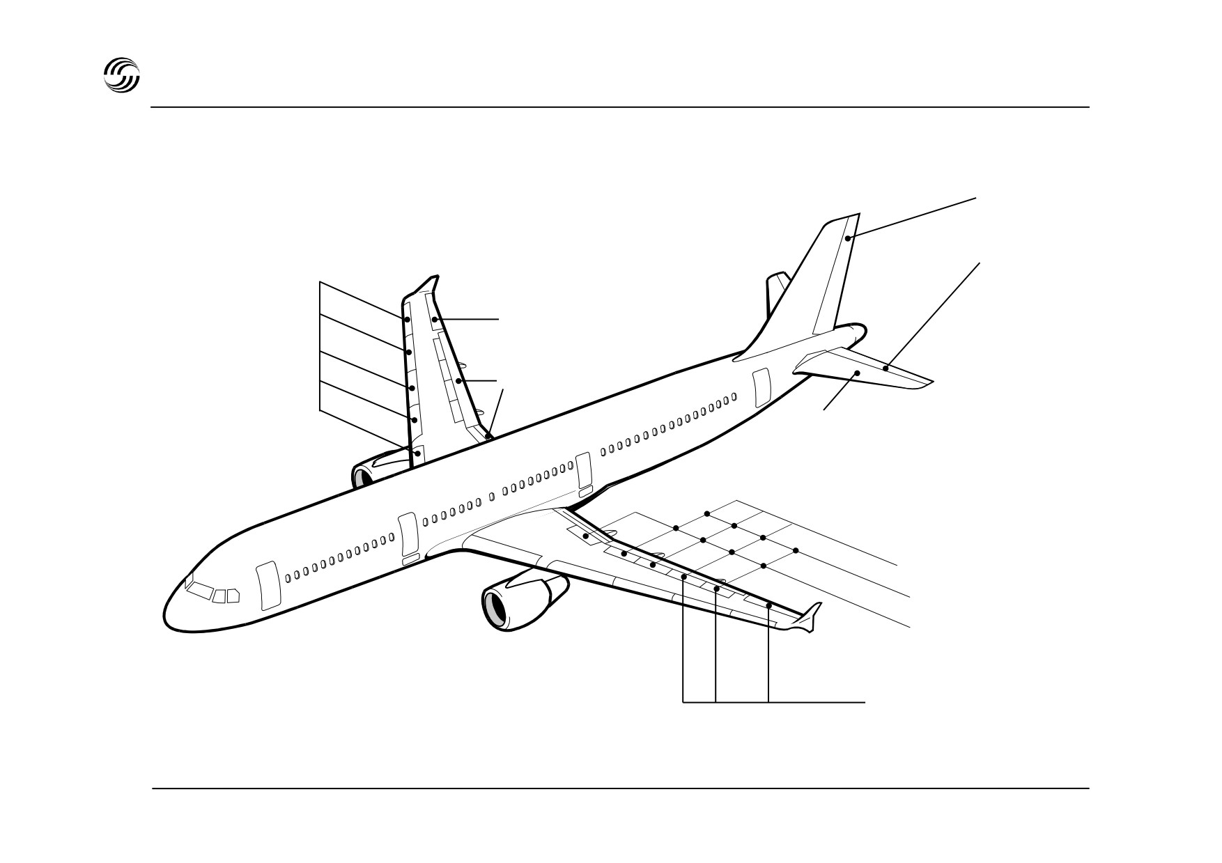
A319/A320/A321 flight controls surfaces
Rudder
Elevator
Slats
Aileron
Flaps
Trimmable horizontal
stabilizer
Speed brakes
Roll spoilers
Lift dumpers
Load alleviation function
(only for A320)
STL 945.7136/97
5.4

A319/A320/A321 flight controls surfaces
z Control is achieved through conventional surfaces
z All the surfaces are hydraulically actuated
z Roll and pitch control is electrical :
- elevator
- ailerons
- roll spoilers
- trimmable horizontal stabilizers
- slats and flaps (single flap surfaces for A320 and
A319, double slotted surfaces for A321)
- speedbrakes / ground spoilers.
z Yaw control is mechanical :
- rudder (yaw damping, turn coordination and trim are
electrically ensured)
z Mechanical back up :
- trimmable horizontal stabilizers
STL 945.7136/97
5.5
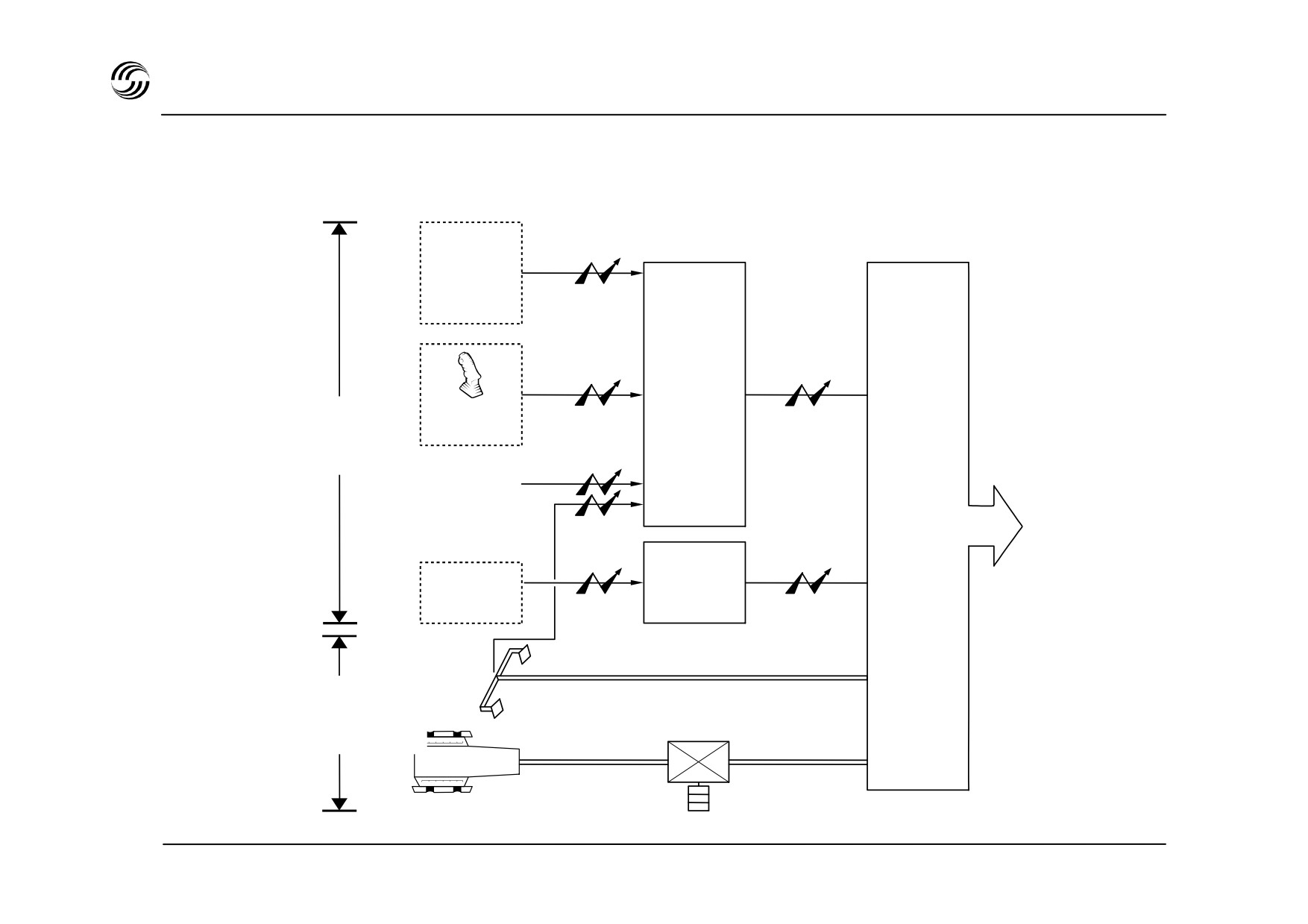
A319/A320/A321 EFCS command principle
Commands
Digital
Electro / hydraulic
computers
jacks
Autopilot
ELACS (2)
SECs (3)
Sidestick
Electrical
orders
Elevator
FACs (2)
Stabilizer
Ailerons
Hyd.
Spoilers
jacks
Rudder
Slats
SFCCs (2)
Slats/flaps
Flaps
Rudder
pedals
Mechanical
back up
STL 945.7136/97
5.6

A319/A320/A321 EFCS computer
Flight control is achieved by three types of computer :
z Two ELACs (Elevator Aileron Computer) to ensure
commands of :
- normal elevator and stabilizer
- aileron
z Three SECs (Spoiler Elevator Computer)
- three computers achieve spoiler control
- two of them are devoted to standby elevator and
stabilizer control
z Two FACs (Flight Augmentation Computer)
Two computers which achieve electrical rudder control
and characteristics speeds calculation for displays on
PFD
In addition
- two SFCCs (Slats Flaps Control Computer)
- two FCDCs (Flight Control Data Concentrator)
acquire data from ELACs and SECs and send them
to ECAM and CFDS.
STL 945.7136/97
5.7


Classic and Fly-by-Wire (FBW) controls compared
Classic flight controls
Fly-by-wire controls
z Directly proportional relationship between pilot stick
z No directly proportional relationship between pilot stick
input and control surface position.
input and control surface position.
z Aircraft response depending on aircraft dynamics and
z Computers’ response to stick input modulating
flight envelope area coverage.
servocontrolled jacks to satisfy :
z Airworthiness and aircraft performance requirements
- normal, alternate or direct laws (pitch, roll and yaw
leading to increasingly complex system :
axes),
- optimised flight control characteristics (easy
- variable artificial feel to modulate pilot forces with
handling, good stability),
flight conditions (efforts / g),
- improved safety :overspeed, stall, windshear,
- hydraulically powered servocontrols, servoed
manoeuvre and attitude protections.
autopilots, control wheel steering,
- stall protection devices (stick shaker, stick pusher),
- stability augmentation systems (Mach trim, speed
trim, angle-of-attack trim, roll and yaw damping).
STL 945.7136/97
5.9

A319/A320/A321 C* law description
Autotrim function
Control surface autotrim
function
Ground or Z < 100 ft*
Ground
Electric trim
GAIN
NZ
GAIN
(and Ø compensated)
GAIN
Z < 100 ft*
THS
Elevator
Z < 100 ft*
* Before landing
STL 945.7136/97
5.10

A319/A320/A321 normal law - pitch axis
z Manoeuvre demand law as basic flight mode
z Medium-term flight path stability :
- neutral speed stability with full flight envelope
- maintenance of parallel trajectory 1g in pitch even
protection
after atmosphere disturbance.
z Vertical load factor control proportional to stick
z Automatic pitch trim eliminating need to correct for
deflection : C* law
speed or configuration changes :
- independent of speed, weight, center of gravity ;
- electric autotrim function holding elevator position
for constant flight path,
stick displacement :
Nz = n Nz = n + 1g
- control surface autotrim function returning elevators
to the THS trail.
stick neutral :
Nz = O Nz = 1g
z Automatic elevator for bank angle compensation up to
z Flight path stability instead of speed stability
33°.
- control inputs are made to alter the flight path, not
to hold it.
STL 945.7136/97
5.11

A319/A320/A321 normal law - pitch axis
z Adaptation of basic control law objectives to :
- Ground phase : ground mode
Direct relationship between stick and elevator
available before lift-off and after touch-down
- Take-off phase : take-off mode
For smooth transition, blend of ground phase law
and Nz command law over 5 seconds after lift off.
- Landing phase : landing mode
At 50ft the attitude is memorized as reference pitch
attitude.
At 30ft this value is progressively reduced to 2°
nose down to induce gentle positive pilot action for
a conventional flare.
STL 945.7136/97
5.12

A319/A320/A321 normal law - roll and yaw axes
z
Roll rate demand (15° / Sec max.) as basic flight
z
Engine failure or aircraft asymmetry compensation
mode :
consisting of :
z
Coordinated roll and yaw surfaces deflections :
- If no pilot action :
stabilized sideslip and bank angle followed by,
•
- to achieve and maintain bank angle up to 33°, stick
automatic rudder trimming to compensate
•
released
asymmetric thrust
slowly diverging heading.
•
z
Bank angle protection above 33° :
- Recommanded action :
- positive spiral stability restored up to
67° inside
zero sideslip target with pedals (take-offf, go-
•
normal flight envelope
around),
- limit of 67° bank angle
heading stabilization with stick input,
•
steady flight stick free / no pedal forces (rudder
•
z
Lateral control laws providing handling quality features
trim).
such as :
z
Adaptation of basic control law objectives to :
- bank angle resistance to disturbance, stick free,
- precise piloting
- Ground phase : ground mode
- good turn coordination,
Direct relationship between stick and roll control
•
- dutch roll damping,
surfaces
- sideslip minimization.
Rudder : mechanical control from pedals + yaw
•
damper function
z
Sidestick free with pedal deflection results in stabilized
sideslip and bank angle facilitating “de-crabbing” in
z
Transition from ground to in-flight law
(and vice
crosswind landings.
versa)
Switching over in 0.5 second after lift-off or touch-
down.
STL 945.7136/97
5.13
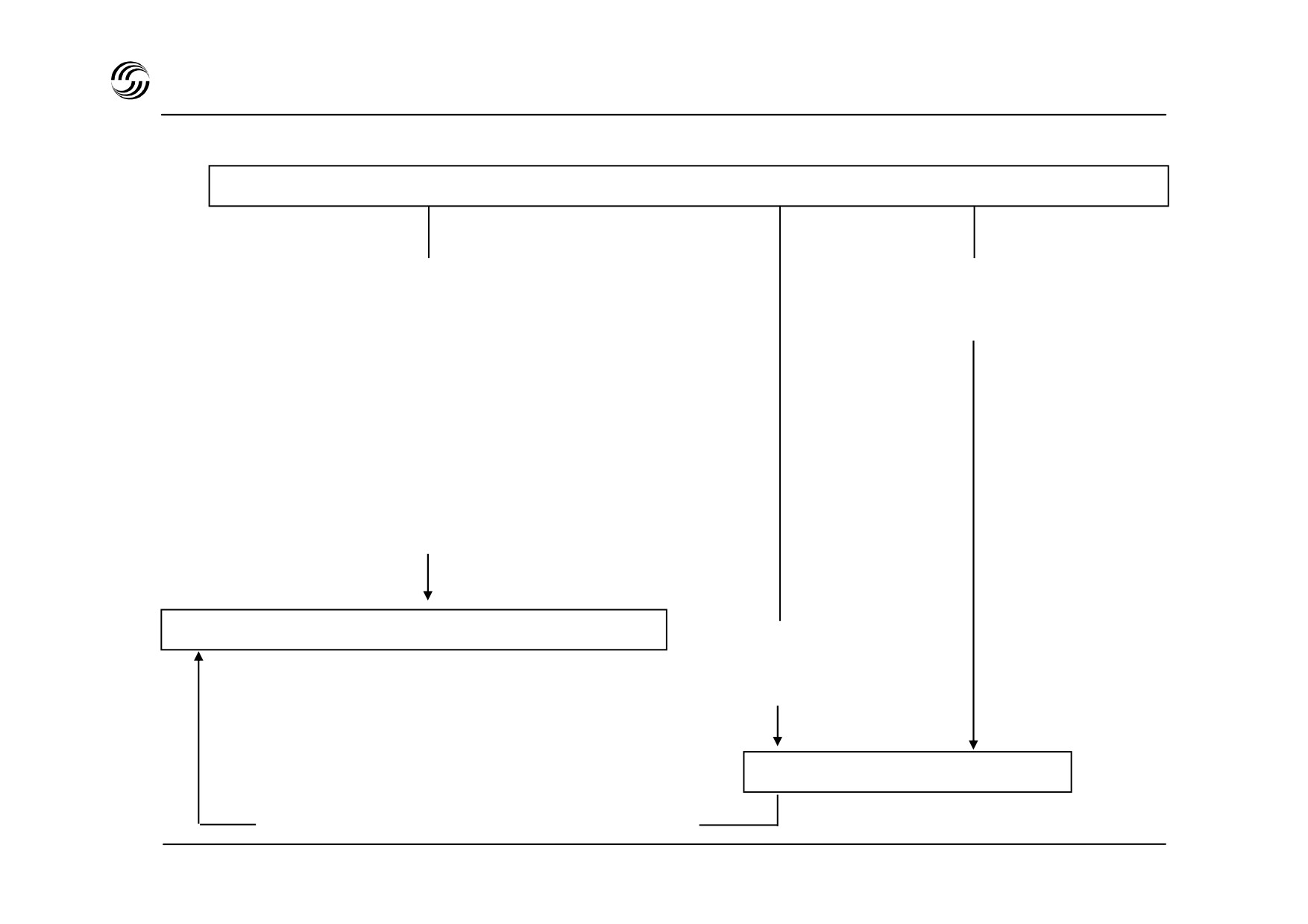
A319/A320/A321 control laws - reconfiguration logics
Normal law
Double self-detected ADC or IRS failure
Triple IRS failure
or double (2nd not self-detected) ADC failure
or double radio-altimeter
or triple ADC failure
failure (when landing gear
or double ELAC failure
extended)
or double FAC failure
or double SFCC slat channel failure
or double hydraulic failure (B+G) or Y+G)
or double aileron failure
or loss of all spoilers
or THS jammed
or emergency power supply
Alternate law
Double (2nd not
self-detected
IRS failure
Direct law
Crew action (identification of failed IRS)
STL 945.7136/97
5.14

A319/A320/A321 alternate law
z Flight mode as basic control laws :
- pitch axis
: as normal law, stick deflection to
change Nz,
- roll/yaw axes : direct stick-to-roll-surface
relationship, speed, configuration
and surface availability
dependent,
- automatic pitch trim.
z Loss of flight envelope protections except :
- manoeuvre protection against excessive load
factor
- low speed stability
- conventional aural stall and overspeed warning
z Reversion of basic control law :
- alternate law not being adapted to landing phase -
automatic reversion to direct law after landing
gear extension.
z Automatic reconfigurations after loss of basic control
law in either axis.
STL 945.7136/97
5.15

A319/A320/A321 direct law and mechanical back-up
Direct law
Mechanical back-up
z On all axes :
z Highly improbable operational necessity.
- direct stick to elevator or roll control surface
z To sustain the aircraft during a temporary complete
relationship,
loss of electrical power.
- center of gravity, configuration and surface
availability dependent.
z Longitudinal control of the aircraft through trim
wheel. Elevators kept at zero deflection..
z Manual trimming through trim wheel :
z Lateral control from pedals.
- amber message on PFD
(“USE MAN PITCH
TRIM”)
z Manual trimming through trim wheel :
z Loss of all flight envelope protections :
- red message on PFD
(“MAN PITCH TRIM
ONLY”)
- conventional aural stall and overspeed warning.
z Automatic reconfiguration after loss of basic control
law in either axis.
STL 945.7136/97
5.16

Performance comparison of sidestick/FBW and conventional controls
z A300 flying testbed equipped with dual sidestick/FBW
system
(left side) and control column conventional flight
control system (right side).
z Two pilots twice flew each of the following three flight
conditions in well-specified and demanding experimental
circuits :
-
Flight Director (FD)
: FD and autothrottle system on,
-
ILS (raw data)
: FD and autothrottle system off,
-
NDB (non-precision) : FD, autothrottle and ILS off.
z The following measurements of recorded flight parameters
were calculated when appropriate and compared for flying
with the sidestick and conventional controls :
-
Mean
: average of 1 second values,
-
Standard deviation : amount of variation around the
mean,
-
Rate zero
: number of sign changes per minute,
-
Reversal rate
: number of direction reversals per
minute.
STL 945.7136/97
5.17
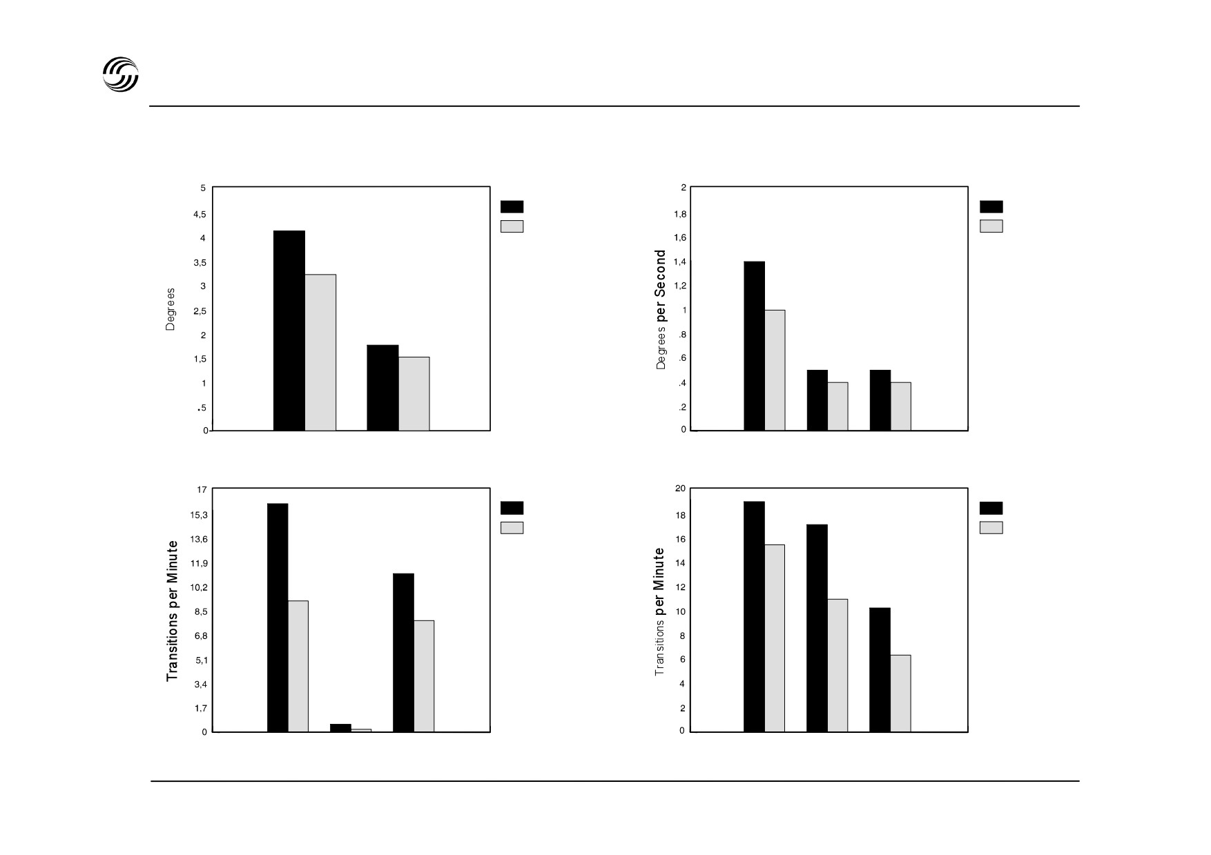
Performance comparison of sidestick/FBW and conventional controls
Roll and pitch angles
Roll, pitch and yaw rates
Standard deviation
Standard deviation
Control
Control
Conventional
Conventional
4
Sidestick/FBW
Sidestick/FBW
4
4
3,2
1
1,6
1,4
.5
.5
.4
.4
Roll
Pitch
Roll Rate Pitch Rate Yaw Rate
Acceleration
Roll, pitch and yaw rates
Transitions through zero
Transitions through zero
Control
19,2
Control
16
Conventional
Conventional
17,5
Sidestick/FBW
Sidestick/FBW
15,7
11,2
9
11,1
10,4
8
6,4
.6
.2
Vertical Longitudinal Lateral
Roll Rate Pitch Rate Yaw Rate
Acceleration Type
STL 945.7136/97
5.18

Performance comparison : major results and conclusions
z All measurements of smoothness and stability
favoured the sidestick by a large margin :
-
for roll and pitch angles and rates, standard
deviations and rate through zero were reduced
by 20% or more when flying with the sidestick,
-
accelerations in all three axes showed a large
reduction in standard deviation and rate
through zero when flying with the sidestick
STL 945.7136/97
5.19
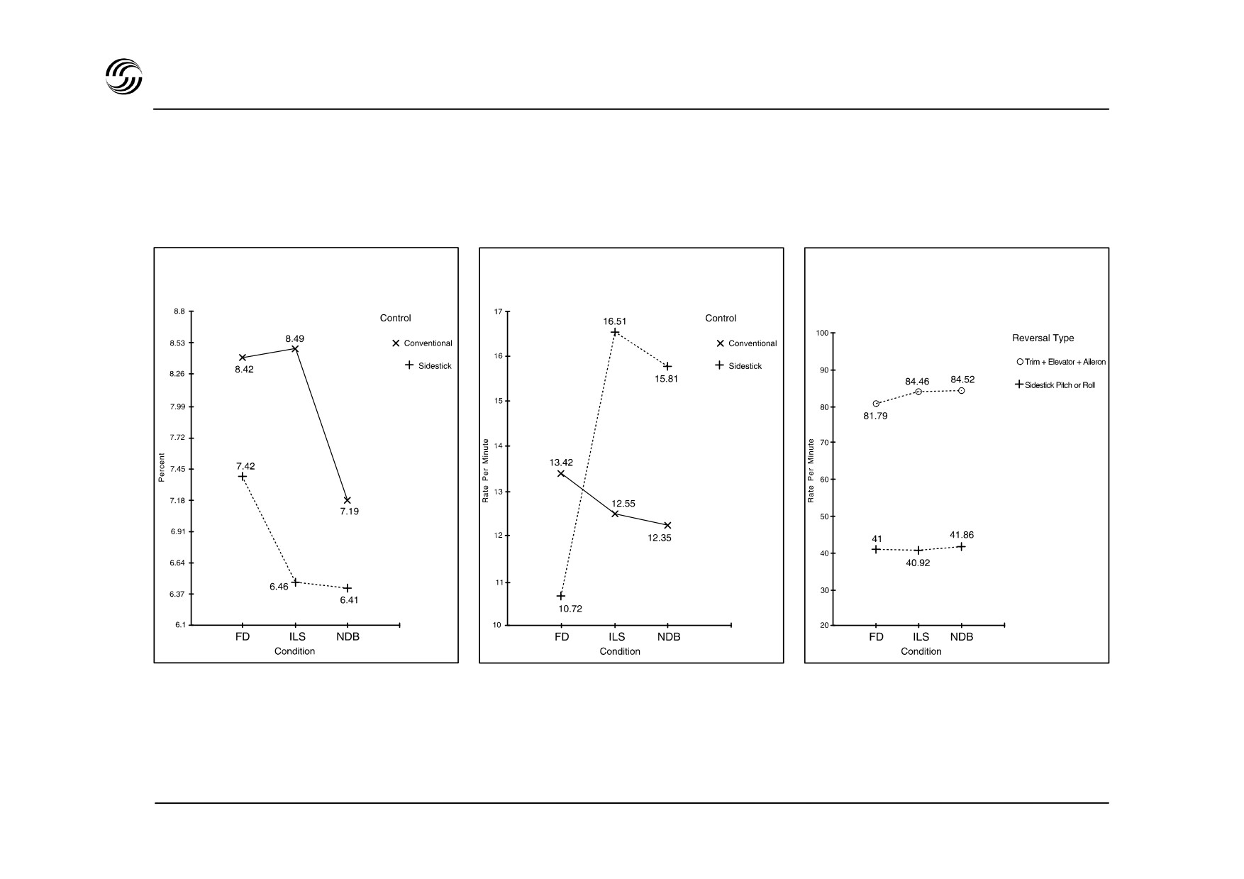
Performance comparison of sidestick/FWB and conventional controls
N1 engine No.1
N1 engine No.1
Pitch trim + elevator
Standard deviation
Reversal rate
+ aileron reversals
vs
Any sidestick reversal
STL 945.7136/97
5.20

Performance comparison : major results and conclusions
z All parameters related to fuel burn showed
significantly better values with sidestick :
-
the sidestick/EFCS combination should
improve fuel economy through unnecessary
control surface movements and increased rear
C.G. limits.
z Pilot control inputs were reduced by 50% or more
and the system still achieved much better overall
performance :
-
lower pilot workload should allow more time for
dealing with emergencies and managing flight
efficiency.
STL 945.7136/97
5.21
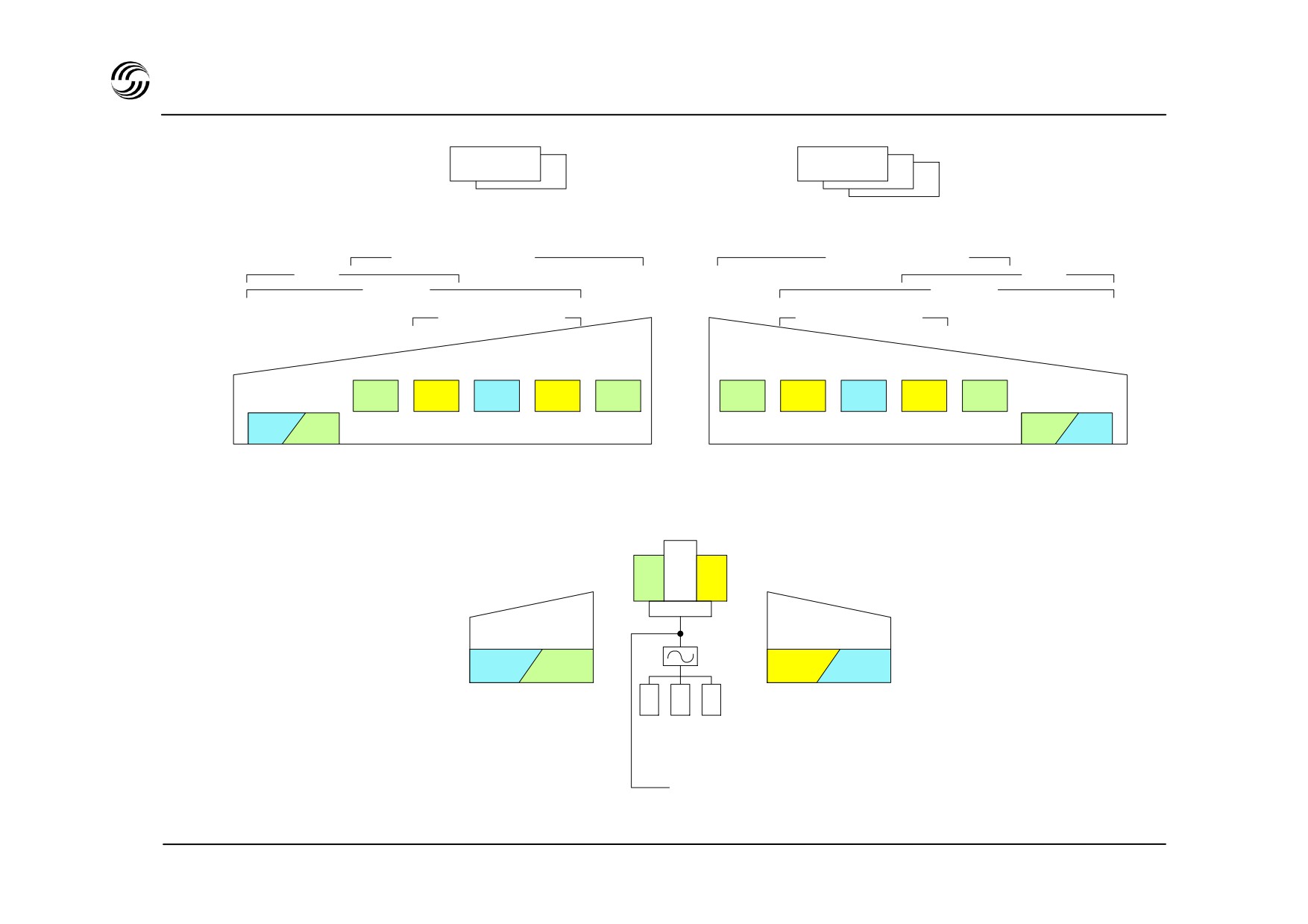
A319/A320/A321 EFCS architecture
ELAC
SEC 1
2
2
3
2 Elevator/Aileron Computers (ELAC)
3 Spoiler/Elevator Computers (SEC)
Ground spoiler
Ground spoiler
LAF*
LAF*
Roll
Roll
Speed brake
Speed brake
LH Aileron
G
Y
B
Y
G
G
Y
B
Y
G
RH Aileron
B G
G B
Normal control
ELAC 1
2
2
1
1
3
3
Normal
3
3
1
1
2
SEC
SEC
control
THS actuator**
G
Y
LH Elevator
LH Elevator
Hydraulic
B
G
Y B
B - Blue system
ELAC 1
2
2
1
2
1 ELAC
G - Green system
SEC 1
2
1
2
2
1 SEC
Y - Yellow system
Mechanical
* LAF = Load Alleviation Function (A320 only)
**THS = Trimmable Horizontal Stabilizer
STL 945.7136/97
5.22

A319/A320/A321 EFCS redundancy aspects
Use of dissimilar redundancy
z Two types of computer
- two ELACs to achieve aileron
control and normal pitch
control
- three SECs to achieve spoiler
control and standby pitch
control
z No single type of µ P :
ELAC - Motorola 68000
SEC - INTEL 80186
z Each ELAC and SEC is divided into two units :
- one Control Unit (COM)
- one Monitoring unit (MON)
z Four different softwares : ELAC COM + MON
SEC COM + MON.
z Physical separation of hardware for COM and MON units.
In addition, mechanical back-up
(through rudder and
stabilizer control) will ensure adequate control in case of
temporary loss of all electrical power sources including
batteries.
STL 945.7136/97
5.23

A319/A320/A321 EFCS electronic protections
Self tests
Other protections
z
Each computer is able to detect its own failures :
z
Specific routes are dedicated to :
control signals
- processor test (check sum, watchdog…)
monitoring signals
- electrical supply monitoring
- input and output test
z
Signals are linked :
- wrap around of output to input.
ELAC 1 and SEC 1 computers on one side
-
ELAC 2, SEC 2 and SEC 3 computers on the other
z
Inputs are monitored :
side.
- by comparison of signals of the
same type but
z
ELAC and SEC computers are qualified in
sent by different sources
convenience with DO 160 for electrical susceptibility
- by checking the signal coherence.
test, the most severe category (Z) being applied.
- Wires are installed in metal shields in the exposed
areas.
- For each signal, wires are twisted.
- No signal grounding in the exposed areas.
- Computer inputs and outputs connected to
exposed wires are protected against the most
severe spikes.
z
This protection, combined with the precautions taken
in the software, ensure good protection against
lightning strikes and electromagnetic disturbances.
STL 945.7136/97
5.24
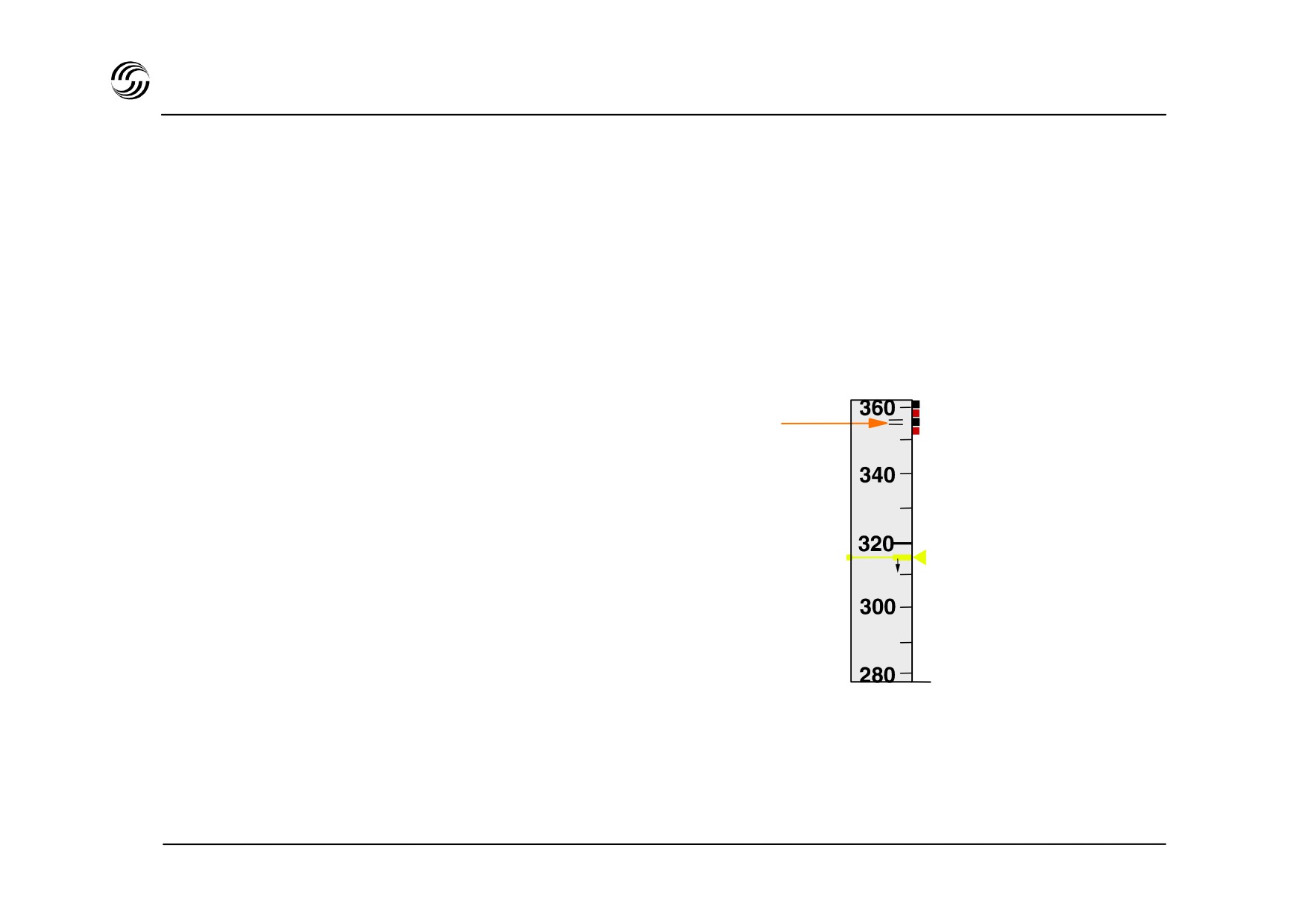
A319/A320/A321 EFCS flight envelope protection
Overspeed protection
z Positive load factor demand automatically applied
when Vmo + 6kt ot Mmo + 0.01 is reached,
-
z Speed limited to Vmo + 16kt and Mmo + 0.04 when
full nose-down stick is maintained,
z Vmo/Mmo warning :
Overspeed
- continuous repetitive chime
protection
- master warning light
symbol
- overspeed red message on ECAM
- red and black strip along the PFD scale.
PFD
speed scale
z Bank angle limitation to 45°
STL 945.7136/97
5.25
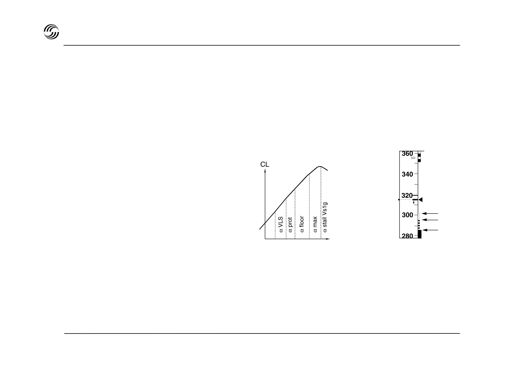
A319/A320/A321 EFCS flight envelope protection
z
AOA protection - principle
- When becomes greater than prot, the flight
control normal law is replaced by an angle of
attack law (angle of attack corresponds to stick
displacement). Autotrim stops, resulting in a
nose-down tendency.
- If reaches floor the auto-thrust system will
apply go-around thrust.
- The max cannot be exceeded even if the stick
is pulled fully back.
- At max + 4° an audio stall warning (cricket +
VLS
synthetic voice) is provided.
Amber
Vprot
Black amber
Vmax
z
Consequences
Red
-
prot is maintained if sidestick is left neutral
-
max is maintained if sidestick is deflected fully
aft
- Return to normal law is obtained when sidestick is
pushed forward.
z
Amber strip on PFD indicates 1.13 Vs at take-off, or
1.23 Vs in other phases of flight.
STL 945.7136/97
5.26
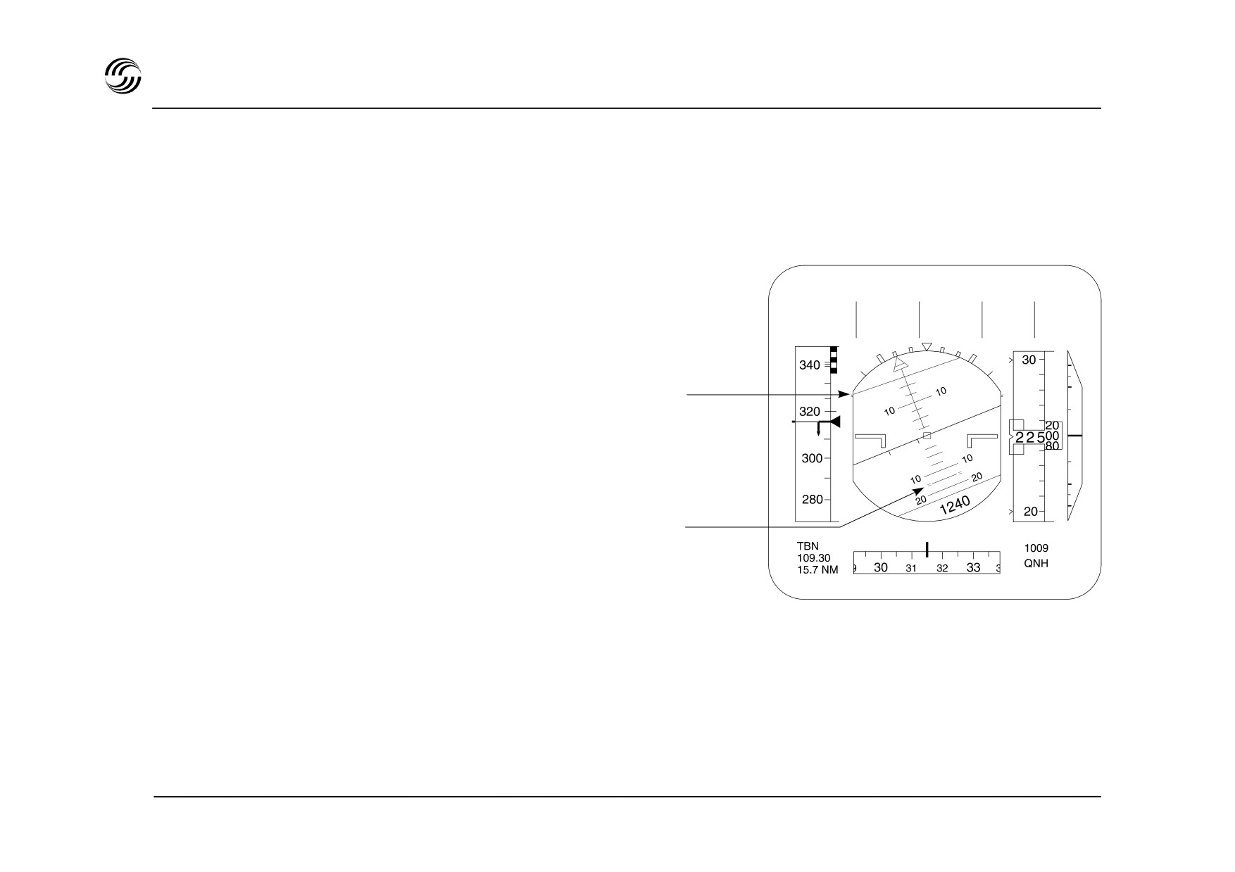
A319/A320/A321 EFCS flight envelope protection
z Manoeuvre protection
Primary Flight Display
The objective is to limit the load factor so as to allow
the pilot to apply full sidestick deflection when high
manoeuvrability is required.
Load factor limits : + 2.5g to 1g in clean configuration
+ 2g to 0g flaps extended.
Bank
z Attitude protection
limitation (67°)
The objective is to complement AOA and high speed
protection in extreme conditions and in windshear.
Bank is limited to : 33° stick released
67° stick fully deflected.
Pitch
limitation (15°)
Pitch is limited to : 30° nose up
15° nose down.
If these limits are approached, the aircraft pitch and
roll rate decrease and stop at the limit.
STL 945.7136/97
5.27


A319/A320/A321 EFCS flight envelope protection
z Windshear protection
z Load Alleviation Function (LAF) (only for A320)
Windshear protection is ensured by :
- The load alleviation function is used in conditions
of turbulence in order to relieve wing structure
- SRS more
loads
- speed trend indication
- wind (speed and direction indication)
- The LAF becomes active at more than
0.3g in
- flight path vector
which case the ailerons and the spoilers 4 and 5
- high angle of attack protection
are deflected symmetrically upwards
- windshear warning (optional).
- The LAF is no longer necessary for A321
and
z Low energy protection (basic on A321 and A319)
A319 which benefit from a reinforced structure.
- An audio warning “SPEED, SPEED, SPEED” is
triggered to indicate to the crew that a thrust
increase is necessary to recover a positive flight
path angle through pitch control.
STL 945.7136/97
5.29
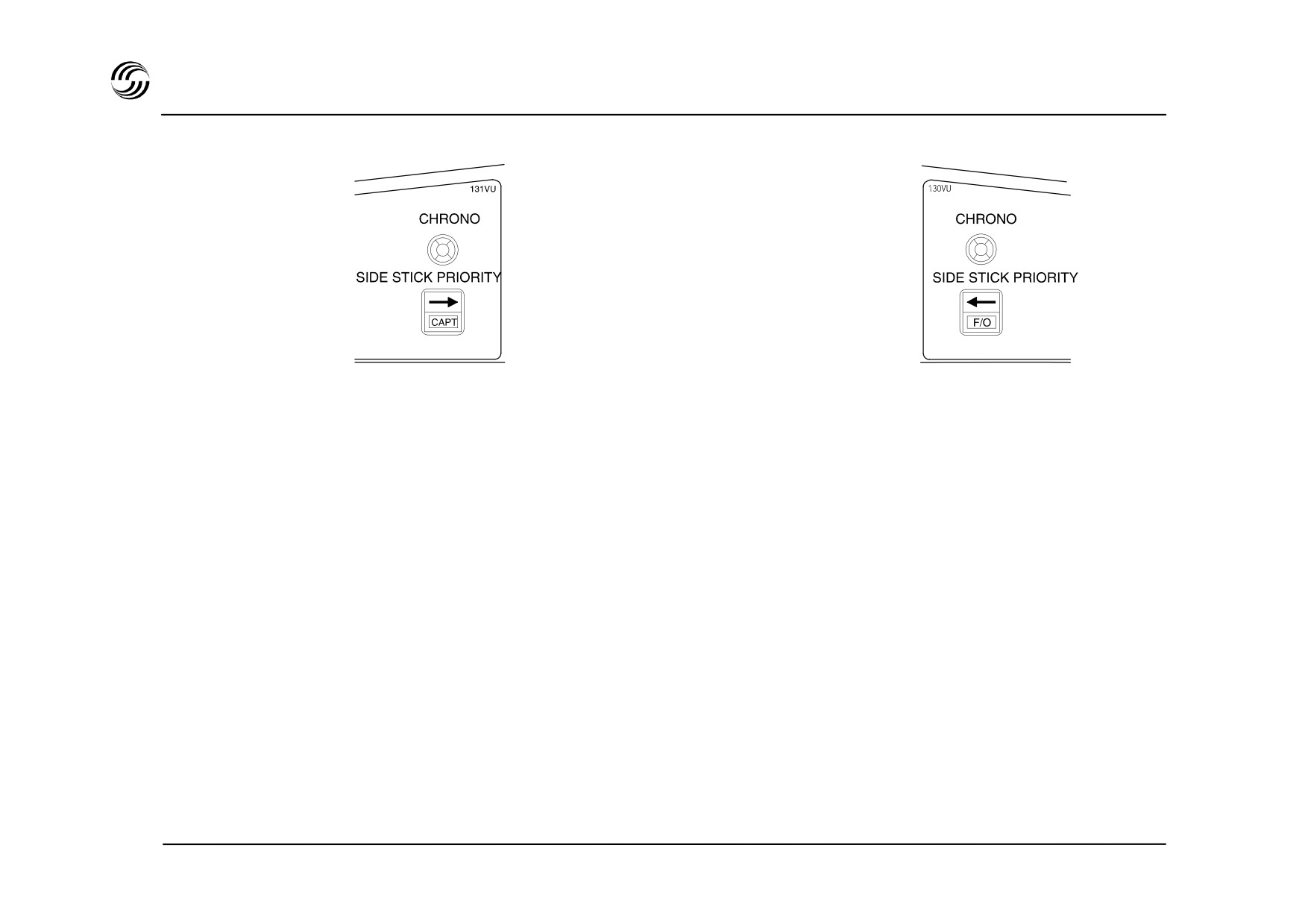
A319/A320/A321 EFCS flight sidestick coupling/function
Priority lights in front of CAPT and F / O
Red
Red
Green
Green
z Both sidesticks are coupled electronically to deal
with :
- simultaneous inputs
- conflicts.
z Full control is obtained by pressing and keeping
pressed the take-over button, thereby deactivating
the other pilot’s stick.
z After pressing the take-over button for more than 40
seconds, it can be released without loosing priority.
z When both pilots press their take-over buttons, the
last pilot to press will get the priority.
z onside priority can be maintained throughout by
keeping the button pressed continuously for 40s.
STL 945.7136/97
5.30
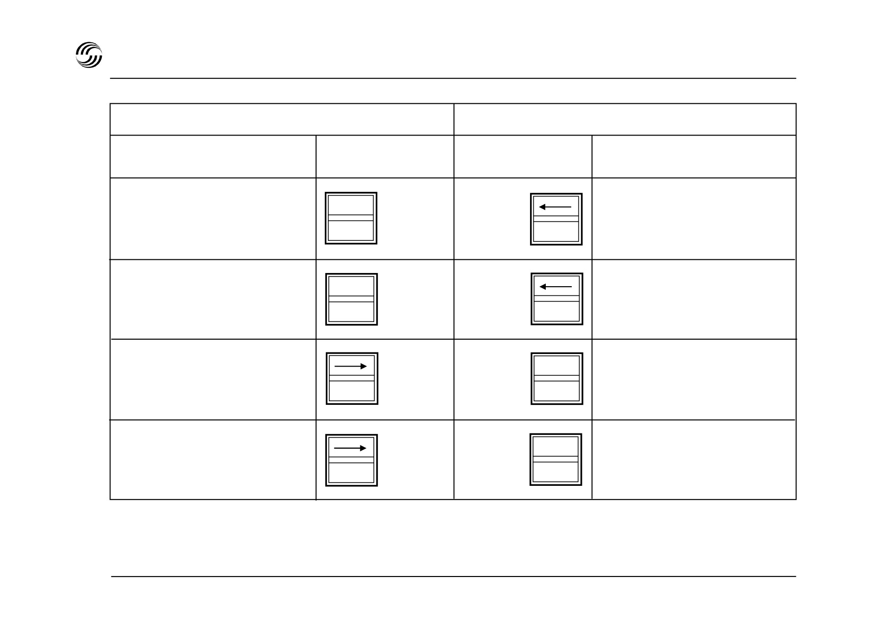
A319/A320/A321 EFCS sidestick priority display logic
Captain’s side
First Officer’s side
Sidestick
Annunciation
Annunciation
Sidestick
Red
Take-over button
Sidestick deflected
depressed
CAPT
Green
Red
Take-over button
Sidestick in neutral
depressed
Red
Take-over button
Sidestick deflected
Green
F/O
depressed
Red
Take-over button
Sidestick in neutral
depressed
Red arrow in front of
Green arrow in front of
the pilot = loss of authority
the pilot = authority when
opposite sidestick deflected
“PRIORITY RIGHT/LEFT” audio voice message when priority is taken.
STL 945.7136/97
5.31
A319/A320/A321 EFCS speed brakes and ground spoilers
z
Speed brakes
- Achieves by three surfaces
- When the sum of a roll order and a simultaneous
speed brake order on either surface is greater
than the maximum deflection achievable, the
symmetrical surface is retracted until the
difference between both corresponding surfaces
is equal to the roll order.
z
If engine power is above idle, an amber message is
displayed on ECAM.
RET
RET
z
Speedbrakes are automatically retracted when :
- selection of flaps configuration FULL for A320 and
SPEED
A319 (or 3 or FULL for A321)
BRAKE
1/2
1/2
- AOA protection is active
z
Ground spoilers
FULL
FULL
- Preselection achieved :
•
with control handle in the armed position and
idle thrust selected, or
•
by selecting reverse thrust
- Maximal extension
(50°) of all surfaces then
automatically achieved when wheels speed
>72kt.
STL 945.7136/97
5.32
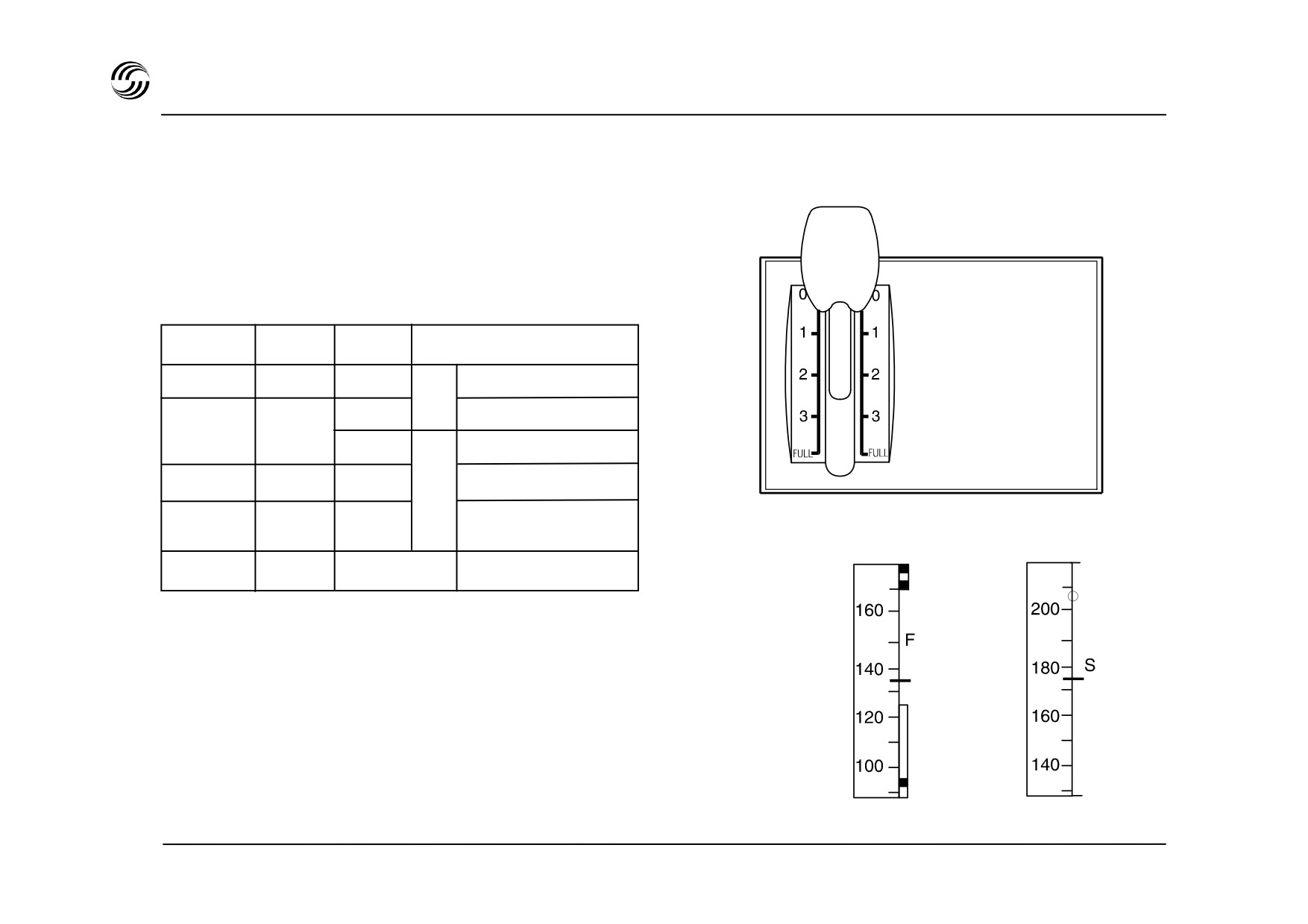
A319/A320/A321 EFCS - flaps and slats control
- The flaps lever selects simultaneous operation of
the slats and flaps.
- The five positions of the lever correspond to the
following surfaces positions and flight phases :
Position
Slats
Flats
Flight phases
FLAPS
0
0°
0°
Cruise / Hold
1
18°
0°
Hold / Approach
10°
Take
2
22°
15°(14°)
Approach
off
3
22°
20°
Approach / landing
(21°)
FULL
27°
35°(*) (25°)
Landing
(*)
:
40° for A320 with IAE engine or A319
()
:
setting for A321
-
Computed by FACs, retraction speeds are
presented on PFDs for :
• minimum flaps retraction or F -speed,
•
minimum slats retraction or S -speed.
STL 945.7136/97
5.33
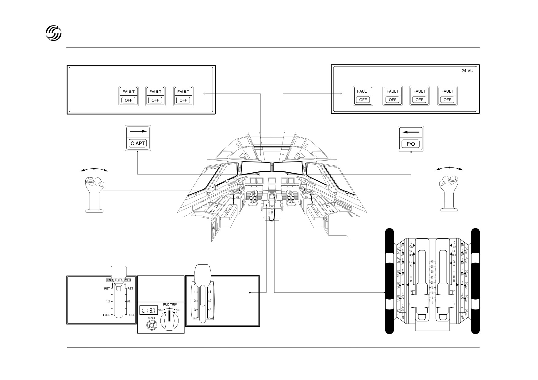
A319/A320/A321 EFCS controls
FLT CTL
FLT CTL
ELAC 1
SEC 1
FAC 1
ELAC 2
SEC 2
SEC 3
FAC 2
SPEED
FLAPS
BRAKE
STL 945.7136/97
5.34
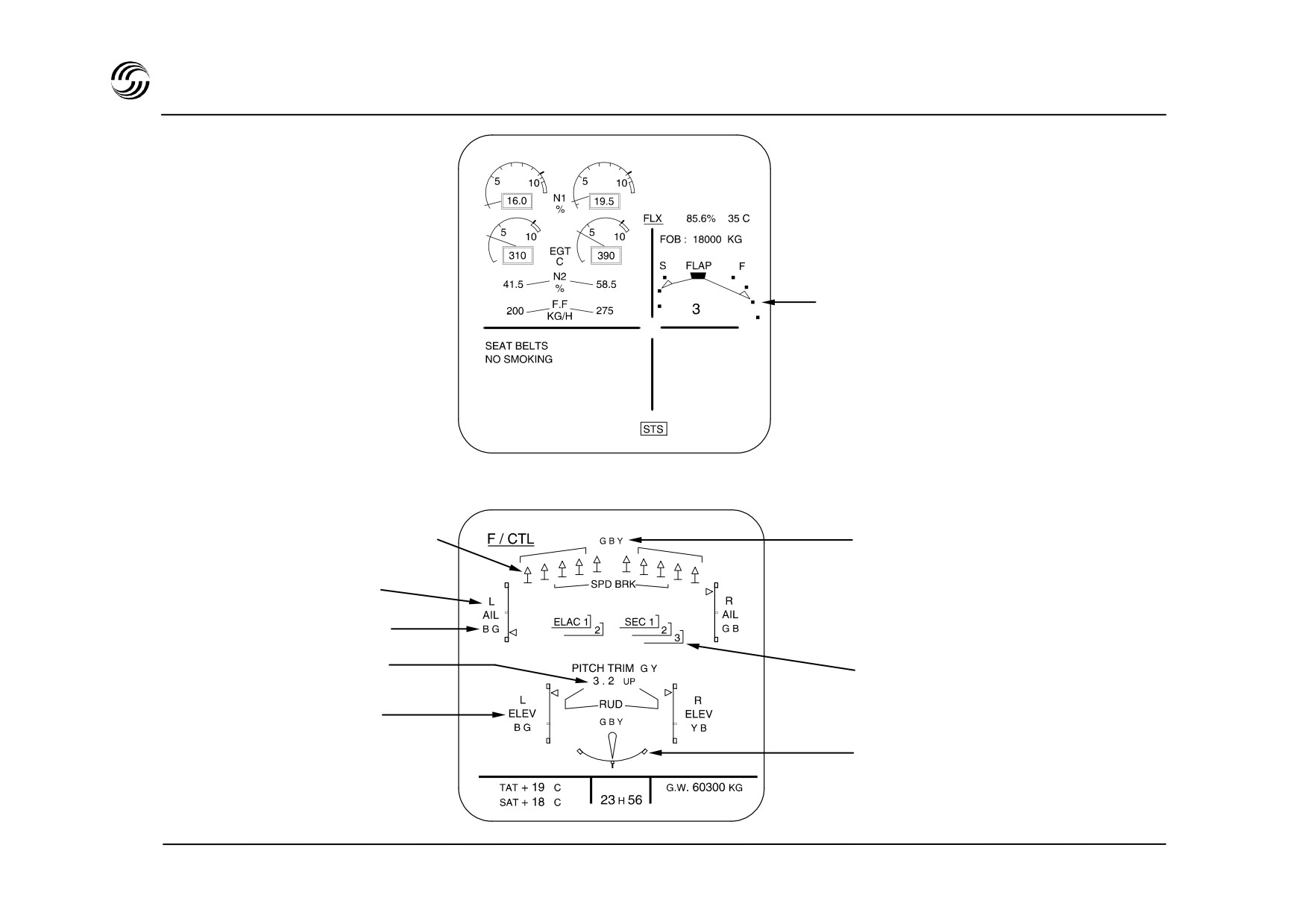
A319/A320/A321 EFCS indications
ECAM upper display
Slats/flaps indication
ECAM lower display
F / CTL page
Spoilers / speedbrakes
Hydraulic system pressure indication
Ailerons position
Ailerons actuators
Pitch trim position
Computers
Elevator position
Rudder position
STL 945.7136/97
5.35


6. Landinggear
STL 945.7136/97
6.1


A319/A320/A321 landing gear
Main feature
Braking system
z Conventional tricycle or bogie (option) landing gear
The Braking and Steering Control Unit (BSCU) is a fully
and direct-action shock absorbers.
digital dual-channel computer controlling the following
functions :
z Main gear retracts laterally and nose gear forward
into the fuselage.
- normal braking system control
- anti-skid control (normal and alternate)
z Electrically controlled by two Landing Gear
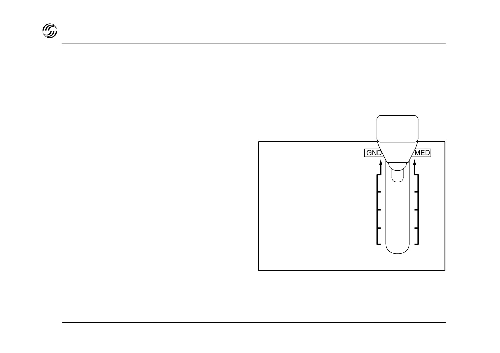
- auto brake function with LO, MED, MAX
Control/Interface Units (LGCIU).
- nosewheel steering command processing
- monitoring of all these functions
z Hydraulically actuated with alternative free-fall/spring
downlock mode
z Alternating use of both LGCIUs for each
retraction/extension cycle.
z In the event of one LGCIU failure, resetting the
landing gear control lever results in transition to the
other LGCIU.
z Elimination of gear lever neutral position through
automatic depressurization of landing gear hydraulic
supply above 260kt.
z Elimination of microswitches by use of trouble-free
proximity detectors for position sensing.
STL 945.7136/97
6.3

A319/A320/A321 landing gear - braking system
Auxiliary LP distribution line
To other side
dual valve
Pedals
Accu
Yellow
Green
HP
HP
Normal
selector valve
Control valve
parking brake
Automatic
BSCU
selector
To other gear
To other
Dual shuttle
wheels
valve
To opposite
Accumulator
wheel
Normal
pressure
servo valve
To ECAM
STL 945.7136/97
6.4

A319/A320/A321 landing gear - braking system
z Carbon disk brakes are standard.
z Parking brake
(Yellow hydraulic system supply or
Yellow brake power accumulator) :
z Normal system (Green hydraulic system supply) :
- electrically signaled
- electrically signalled through anti-skid valves
- hydraulically controlled with brake pressure
- individual wheel anti-skid control
indication on gauges.
- autobrake function
- automatic switchover to alternate system in event
of Green hydraulic supply failure.
z Alternate braking system (Yellow hydraulic system
supply) :
- hydraullically controlled through dual valve
- individual wheel anti-skid control
- no autobrake function.
z Emergency braking system (Yellow hydraulic system
supply or Yellow brake power accumulator) :
- hydraulically controlled by pedals with brake
pressure indication on gauges
- no anti-skid control
STL 945.7136/97
6.5
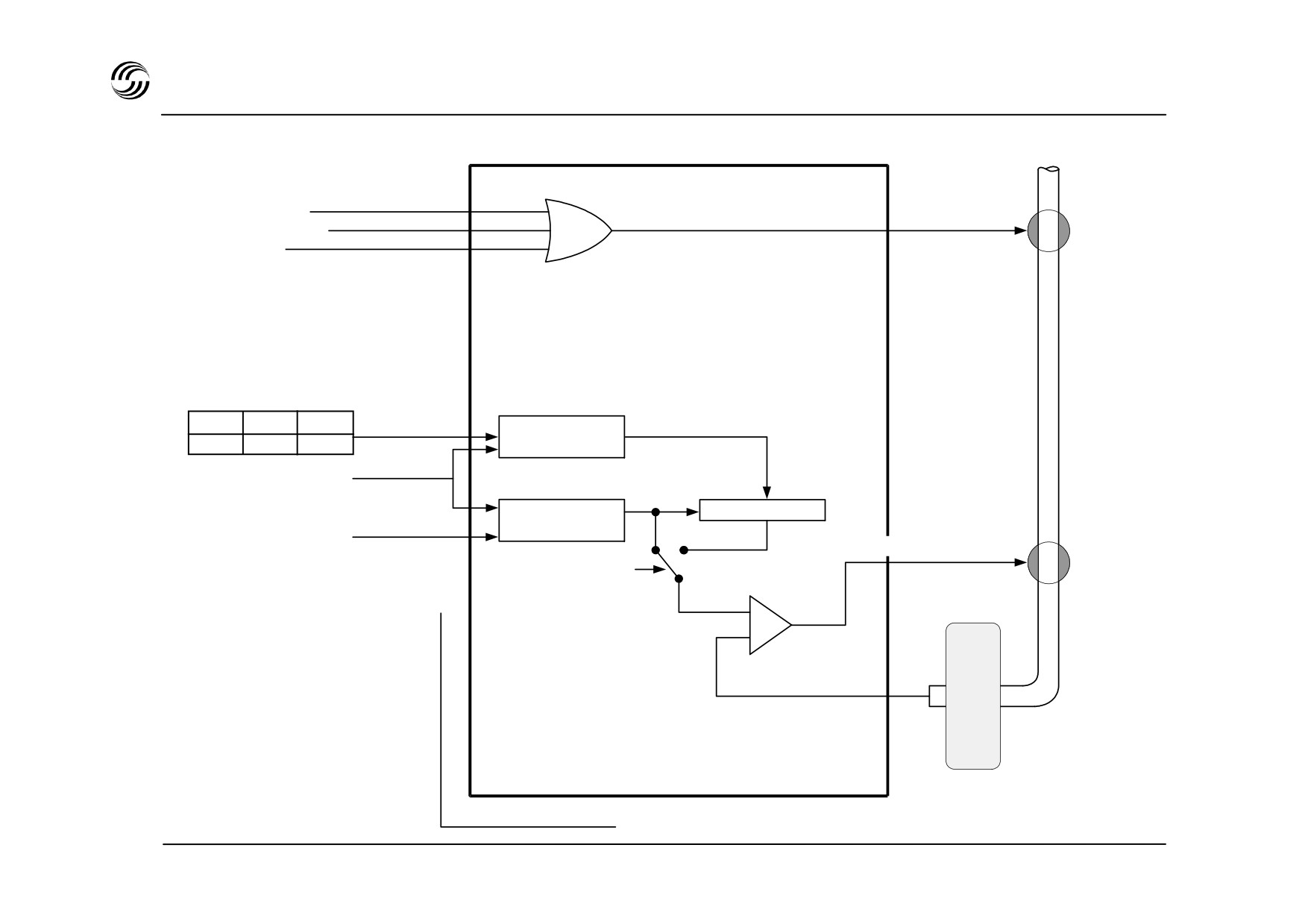
A319/A320/A321 landing gear - antiskid principle
Green H.P.
Pedals depressed
Normal
Opening
autobrake activated
selector
OR
gear retraction
valve
LO MED MAX
Decel
Decel
Decel
prog
V prog
Vo prog
on
on
on
Vo
Aircraft speed at
touchdown
(wheel tachy.)
Highest value
ir
Vo - ir. t
Aircraft longitudinal
On
Release order
deceleration
Off
Normal
Autobrake
servo valve
(ADIRS)
Vref
Wheel speed
BSCU 1
BSCU 2
STL 945.7136/97
6.6

A319/A320/A321 landing gear braking principle
Anti-skid system
z From touchdown, aircraft speed is computed based
on touchdown speed
(wheels) and integrated
deceleration
(ADIRS). This reference speed is
compared with each wheel speed to generate a
release order for closing the normal servo valve in
case of skid exceeding 13%.
z Brake pedals order results in opening this
servovalve also modulated by anti-ski closing
signals.
Autobrake system
z From touchdown a specific speed is computed
based on touchdown speed
(wheels) and
programmed deceleration (low, medium, max). This
programmed speed is compared with each wheel
speed to generate a release order for closing the
normal servovalve to meet selected deceleration.
z If reference speed exceeds programmed speed
(contaminated or iced runways) the former will take
over for the anti-skid to modulate the normal servo
valve.
STL 945.7136/97
6.7
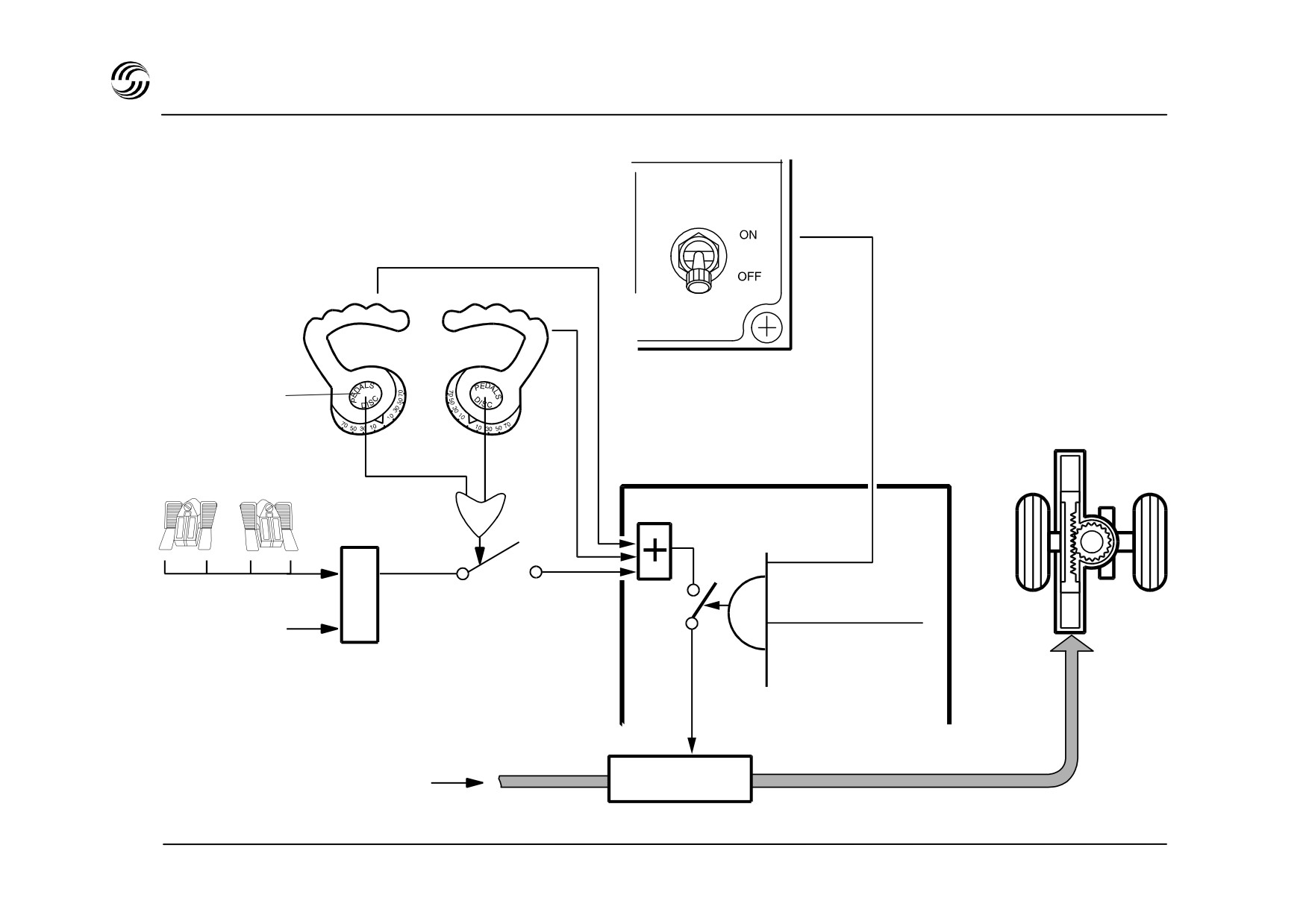
A319/A320/A321 landing gear - nose gear steering principle
A/SKID &
N/W STRG
Rudder pedal
disconnect
pushbutton
OR
E
One engine running
L
A
and
Towing lever
Auto pilot
C
Normal position
MLG Compressed
BSCU
Steering servo
Green hydraulic supply
valve
STL 945.7136/97
6.8
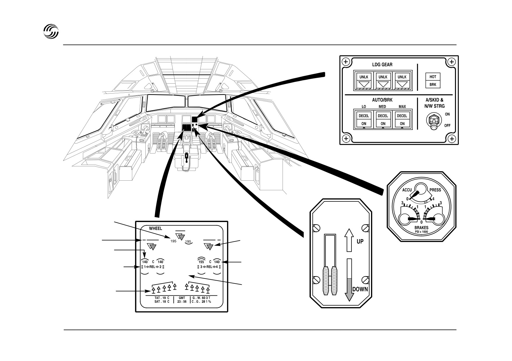
A319/A320/A321 landing gear
Autobrake panel and gear position indicator
(System 1)
Tyre pressure
psi (optional)
Gear downlock
LDG door
indication
Brake pressure
Hottest brake
indication
Brake temp. °C
(alternate system)
Anti-skid release
indicator
Autobrake
Ground spoiler
indication
extension
Wheel system page landing roll
STL 945.7136/97
6.9


7. Fuel system
STL 945.7136/97
7.1
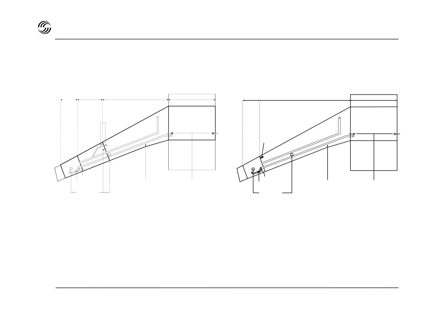
A319/A320/A321 fuel system - ventilation
A319 / A320
A321
Surge tank Outer cell
Inner cell
Center tank
Surge tank
Wing tank
Center tank
Vent valve
Vent valve
NACA intake
NACA intake
Vent line
Pressure relief outlets
Vent line
Pressure relief outlets
Flame arrestor
Flame arrestor
Pressure relief
Pressure relief
outlets
outlets
STL 945.7136/97
7.2

A319/A320/A321 fuel system - basic layout
z Total fuel capacity
z Ventilation
- Each tank is separately ventilated via surge tanks at
each wing tip.
A319 / A320
- The center tank is ventilated via the LH surge tank.
- The surge tanks are opened to atmosphere via
Two outer cells
1 760 litres (1 408kg)
flame arrestors and NACA inlets.
Two inner cells
13 849 litres (11 079kg)
- Vent valves ensure correct operation of the vent
system.
One center tank
8 250 litres (6 600kg)
- Pressure relief outlets protect the tanks from over-
or under- pressure.
A321
Two wing tank
15 500 litres (12 400kg)
One center tank
8 200 litres (
6 560kg)
(Weight calculated with a density of 0.8
An additional center tank (optional) increases the
total fuel capacity by 2 900 litres (2 320kg).
On the A319 Corporate Jet, up to 6 additional
center tanks can be added to increase the total
fuel capacity by up to 17 000 litres.
An additional volume of
2% is available for
expansion without spillage into the vent surge
tank.
STL 945.7136/97
7.3
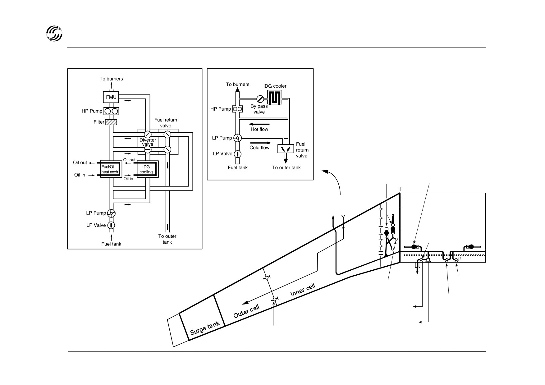
A319/A320 fuel system - engine feed
IAE Eng
CFM Eng
Sequence valves Pump
Fuel recirculation
system
Center
tank
15
Defuel valve
Suction valve
(ground only)
22
(gravity feed)
Cross feed valve
APU LP valve
26
twin actuators
twin actuators
APU
pump
Transfer valves
STL 945.7136/97
7.4

A319/A320 fuel system - engine feed
A319/A320 definition
z Fuel is delivered to the engines by means of booster
pumps.
- Each tank is equipped with two identical booster
pumps.
- Center tank feeds first, except during take-off and
fuel recirculation when center tank pumps are
switched off automatically.
- Wing tank pumps operate permanently at a lower
pressure than center tank pumps.
- Thus, when center tank pumps stop, engine feed
comes automatically from wing tank pumps.
z Two electrical transfer valves are installed on each
wing.
They automatically open when the inner cell fuel
reaches a low level (about 750kg) for fuel to drain
from the outer to the inner cells.
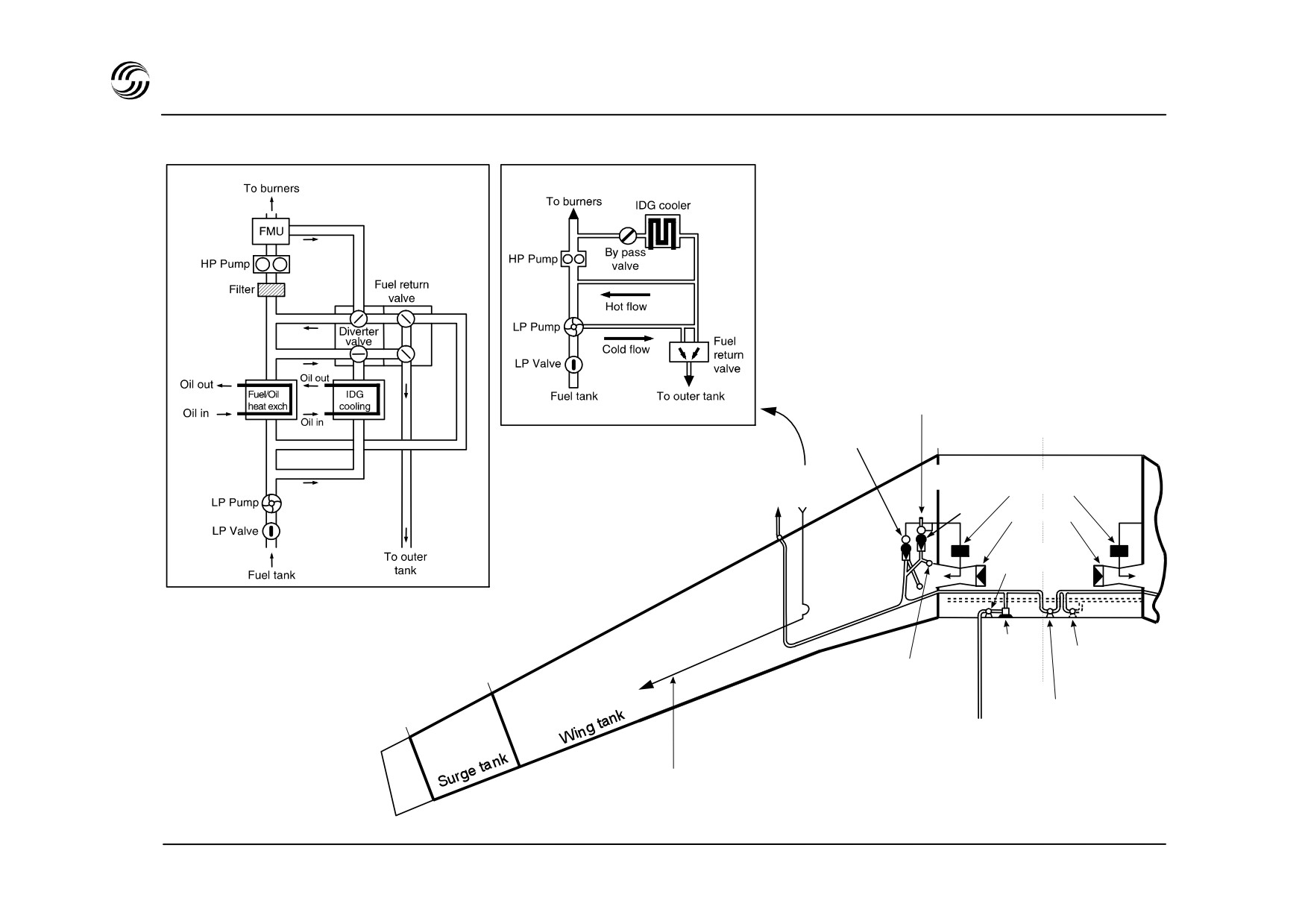
z Fuel is recirculated automatically and transparently
to the crew :
It ensures the IDG cooling (CFM and IAE eng.) and
the engine oil cooling (IAE only) through a set of
valves controlled by the FADEC.
STL 945.7136/97
7.5
A321 fuel system - engine feed
IAE Eng
CFM Eng
Remote pick-up
(all pumps)
Sequence
Center tank
valve
Center tank
Fuel recirculation
transfer valves
system
Pumps
Jet pumps
APU LP valve
(twin actuators)
APU
Defuel/tansfer
Suction valve
fuel pump
Valve twin actuators
22
(gravity feed)
(ground only)
Cross feed valve
26
(twin actuators)
Recirculation line
STL 945.7136/97
7.6

A321 fuel system - engine feed
A321 definition
The A321 fuel system has been simplified compared to
the A319/A320 :
z Single wing tank in place of two cells wing tank,
suppression of the outer/inner cell transfer valves.
z Center tank transfer to wing tank in place of center
tank feed to engines :
When the transfer valves are open, fuel tapped from
the wing pumps flows into the center tank jet pumps.
It creates a depressurization which sucks the center
tank fuel into the wing tanks
- a transfer valve automatically closes when the
related wing tank is overfilled or when the center
tank is empty.
The fuel recirculation principle is identical to
A319/A320, the recirculated fuel being returned into the
wing tank.
STL 945.7136/97
7.7
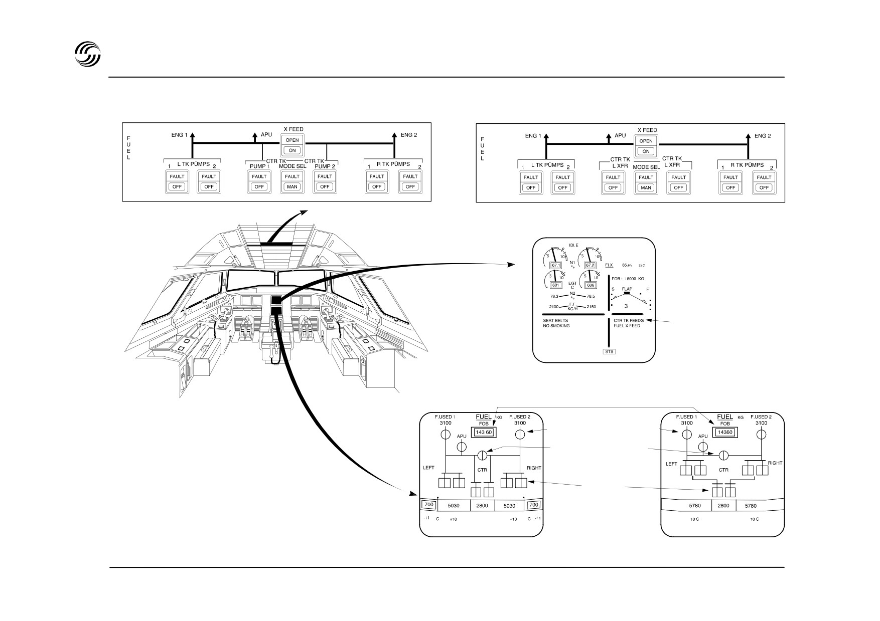
A319/A320A321 fuel system - control and indications
A319/A320
OVERHEAD PANEL
A321
UPPER ECAM
Memo indications :
systems temporarily
used
LOWER ECAM
A319/A320
Fuel on board
A321
Low pressure valve
Cross-feed valve
Pumps
indication
STL 945.7136/97
7.8

A319/A320A321 fuel system - control and indications
z No crew action is required for normal operation.
z Indications :
- fuel data
(quantity, temperature) are available
from a Fuel Quantity Indication (FQI) system
- fuel quantity is permanently displayed on upper
ECAM DU
- fuel system synoptic on lower ECAM DU is
displayed according to ECAM logic
- low level warning is totally independent from FQI.
z Abnormal operations :
- fuel feed sequence may be operated manually
- one or both engines may be fed from any tank via
cross-feed valve
- gravity feed is possible from wing tanks.
STL 945.7136/97
7.9
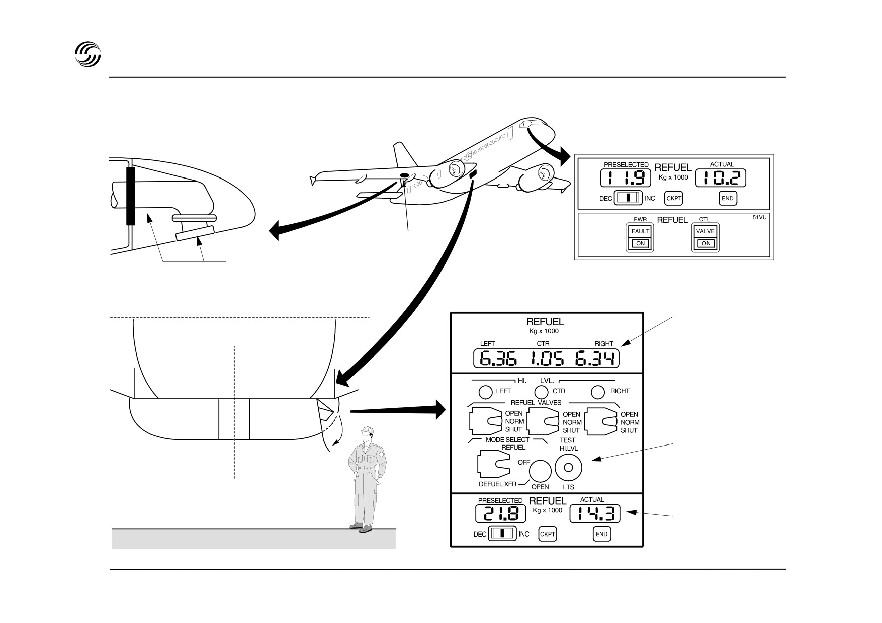
A319/A320A321 fuel system - refuel/defuel
In cockpit (optional)
Refuel coupling
Refuel
coupling and cap
Refuel panel :
Fuselage datum line
Fuel quantity
indicator
Refuel valve
control
Refuel
preselector
STL 945.7136/97
7.10

A319/A320A321 fuel system - refuelling
z Refuel/defuel control is from an external panel
located in the fuselage fairing under the RH wing
within easy reach from the ground.
z One refuel/defuel coupling is located under the RH
wing.
z Identical coupling on LH wing is available as an
option.
z Refuelling is auto sequenced :
It starts with the outer cells (A319/A320) or the wing
tanks (A321).
If the selected fuel quantity exceeds the wing tank
capacity, the center tank is refuelled simultaneously.
z Refuelling time at nominal pressure is approximately
20 minutes for all tanks.
z Gravity refuelling can be achieved by overwing
refuelling points.
STL 945.7136/97
7.11


8. Engine controls
STL 945.7136/97
8.1


A319/A320/A321 engine controls - FADEC
z
Thrust control is operated through Full Authority
z
The system design is fault-tolerant being fully
Digital Engine Control (FADEC) computers which :
duplicated, with
“graceful degradation” for minor
failures (i.e. sensor failures may lose functions but not
- command the engines to provide the best suited
the total system).
power to each flight phase
- automatically provide all the associated protection
The engine shut-down rate resulting from FADEC
required :
failures will be at least as good as today’s latest
hydromechanical systems with supervisory override.
•
either in manual (thrust lever)
or in automatic (autothrust) with a fixed thrust
z
FADEC is an electronic system which incorporates a
•
lever.
fully redundant Engine Control Unit
(ECU) and an
Engine Interface Unit (EIU).
z
Engine performance and safety better than with
current hydromechanical control system.
Each engine is equipped with a FADEC which provide
the following operational functions :
Simplification of engine/aircraft communication
architecture.
- gas generator control
- engine limit protection
Reduction of crew workload by means of automatic
- engine automatic starting
functions (starting, power management).
- power management
- engine data for cockpit indication
Ease of on-wing maintenance.
- engine condition parameters
- reverser control and feed back.
STL 945.7136/97
8.3
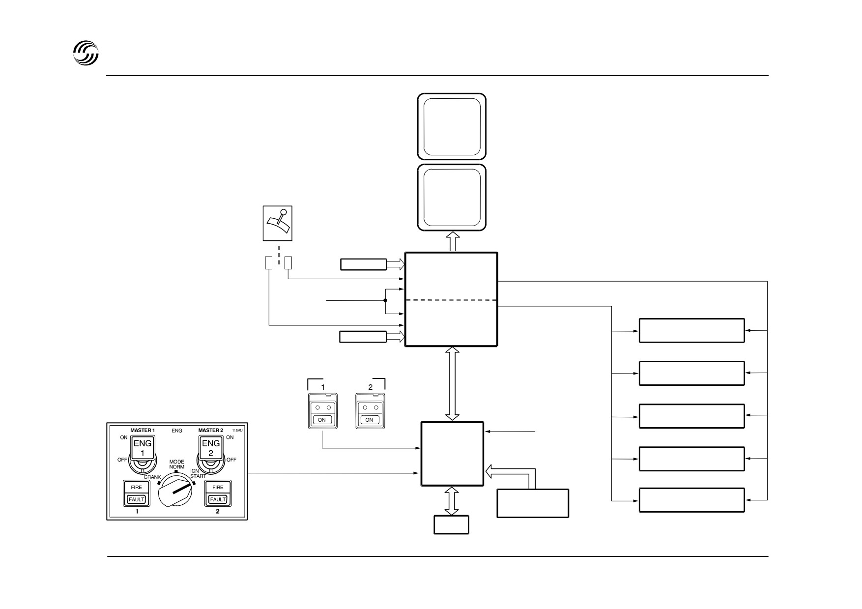
A319/A320/A321 engine controls - FADEC architecture
SYSTEMS
DISPLAYS
ENGINE/
THRUST
WARNINGS
LEVER 1
DISPLAY
ADIRS 1+2
TLAA
ECU CHANNEL. A
ENGINE
PARAMETERS
ECU CHANNEL. B
HYDROMECHANICAL
TLAB
ADIRS 1+2
UNIT
ENG
MAN START
START VALVE
THRUST REVERSER
GRND/FLT
SYSTEM
ENGINE
INTERFACE
UNIT 1
IGNITION SYSTEM
BLEED STATUS
(ECU)
FUEL RECIRCULATION
ZONE
VALVE
CONTROLLER
FMGS
STL 945.7136/97
8.4

A319/A320/A321 engine controls - ECU and EIU
One ECU located on the engine with dual redundant
The interface between the FADEC system and the
channels (active and standby) each having separate 28V
other aircraft systems is mainly performed by the EIU
DC aircraft power sources to ensure engine starting on
through digital data buses.
ground and in flight.
One EIU per engine is located in the avionics bay.
In addition dedicated ECU alternator assures self power
above 12% N2 for CFM56 (10% N2 for IAE V2500).
Care is taken to preserve systems segregation for
safety and integrity.
Dual redundancy for electrical input devices (ADIRS 1+2,
TLAs, engine parameters).
Dual redundancy for electrical part of control actuator.
Simplex system for hydromechanical parts of the control.
Fault tolerance and fail operational capability.
High level of protection against electromagnetic
disturbance.
STL 945.7136/97
8.5
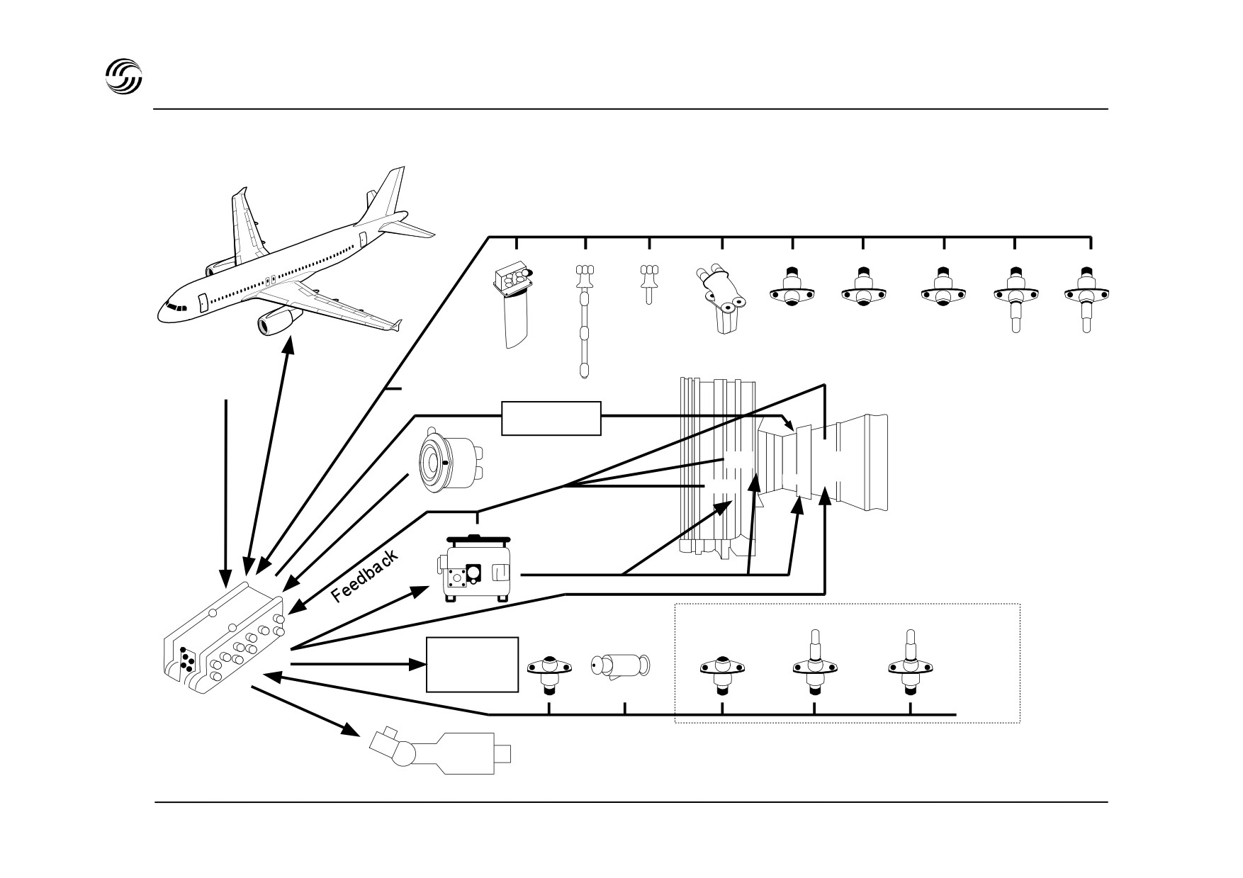
A319/A320/A321 engine controls - CFM56
Control
signals
N2
T25
PS12
PS12
PS3
Tcase
T3
T12
ARINC
28 VDC
data
P
N1
0
buses
Ignition
VSV
HPT
Alternator
CC
Fuel
VBV
Hydromech.
unit
Fuel
PS13
P25
T5
flow
T fuel
Thrust
reverser
Engine
Starter air
Monitoring signals (optional)
control
valve / starter
unit
STL 945.7136/97
8.6
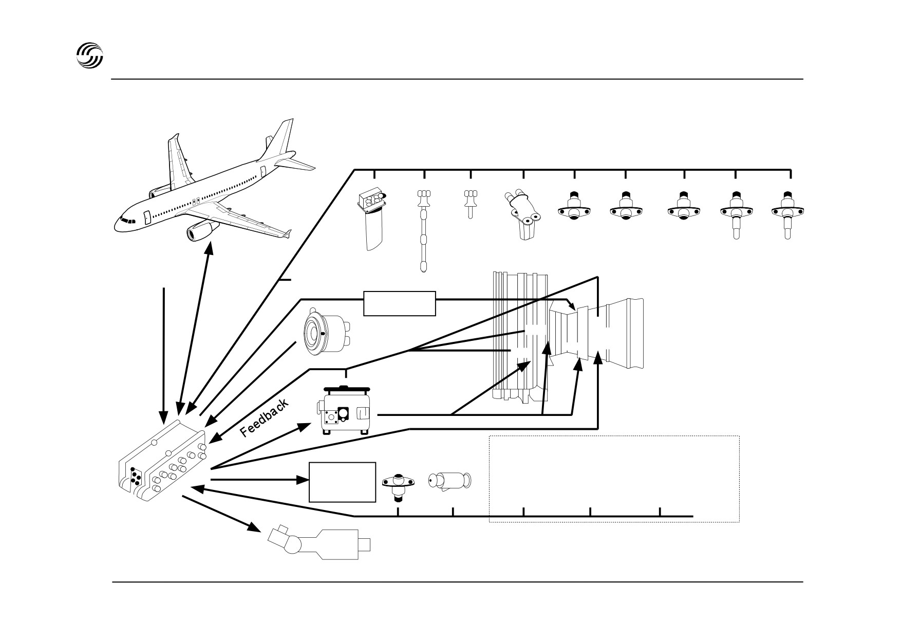
A319/A320/A321 engine controls - V2500
Control
signals
N2
P2
P5
P3
T4.9
T3
Pb
T2
ARINC
28 VDC
data
P
N1
0
buses
Ignition
VSV
Alternator
HPT
Fuel
CC
VBV
Hydromech.
unit
Fuel
flow
T fuel
Thrust
reverser
P
P2.5
T2.5
12.5
Electronic
Starter air
Monitoring signals (optional)
engine
valve / starter
control
STL 945.7136/97
8.7
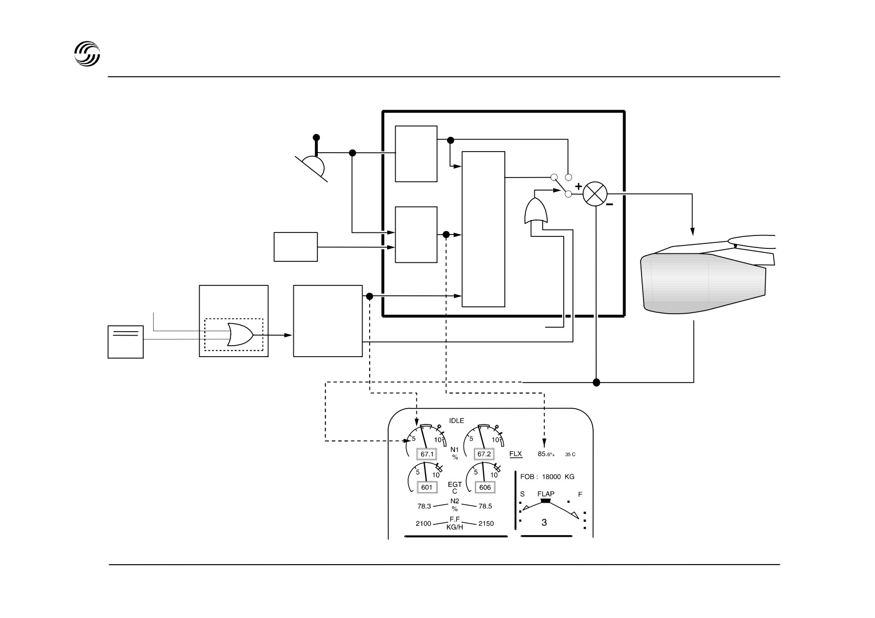
A319/A320/A321 engine controls - thrust control schematic
CFM56
ECU
N1
THR
N1
Thrust
Auto
lever
Manual
mode
comput.
mode
Fuel flow
N1
control
N1
or
N1 limit
limitation
limit
compu
ADC
tation
N1 target
TLA out of
FMGC
ATS range
ATS
EIU
Instinctive
or
disconnect PB
ATHR
ATS not active
Disengaged
Actual N1
Upper ECAM DU
STL 945.7136/97
8.8
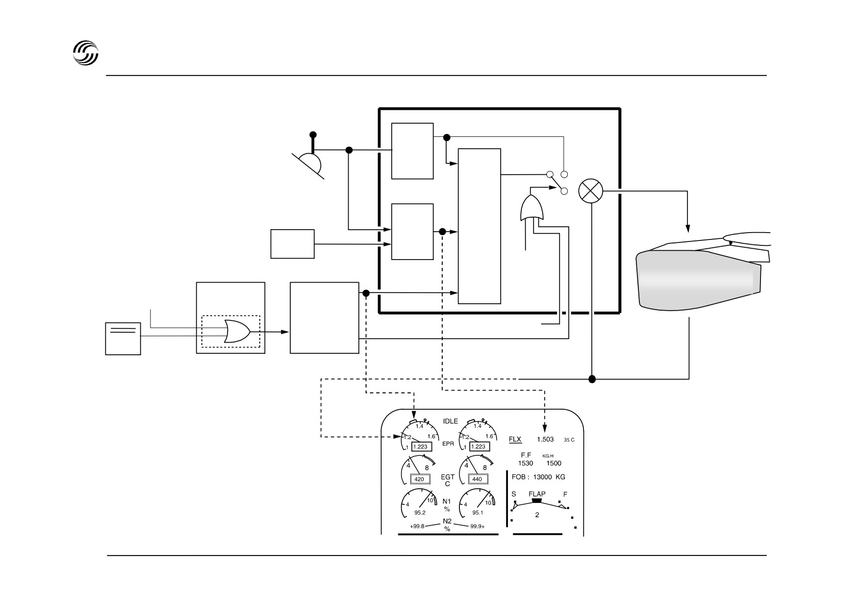
A319/A320/A321 engine controls - thrust control schematic
IAE V2500
EEC
EPR
Trottle
EPR
Thrust
Auto
lever
Manual
comput.
mode
mode
+
Fuel flow
EPR
target
-
control
or
EPR
EPR
limitation
limit
limit
computa.
ADC
and selec.
N1 mode
selection
EPR target
TLA out of
FMGC
ATS range
EIU
Instinctive
ATS or
disconnect PB
ATHR
ATS not active
Disengaged
Actual EPR
Upper ECAM DU
STL 945.7136/97
8.9

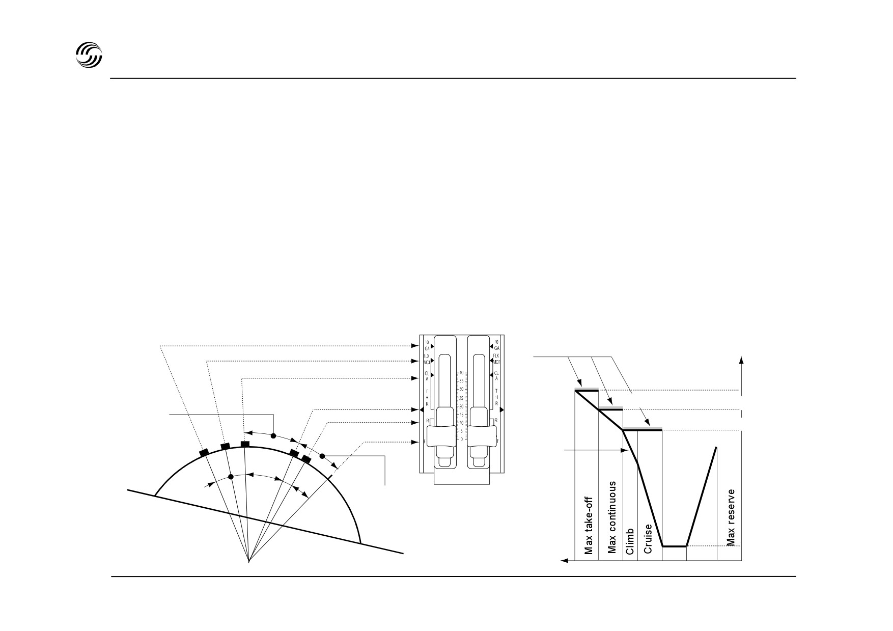
A319/A320/A321 engine controls - thrust control operations
Limited thrust parameters
(N1
for CFM56, EPR for
Thrust lever only to be moved manually
(no
V2500) computed by FADEC.
servomotor)
:
lever position not necessarily
representing engine thrust delivered
Selection of thrust limit mode obtained directly by throttle
position :
According to the thrust lever position the FADEC
Six positions defined by detents or stops.
computes :
-
Thrust rating limit (no TRP)
-
N1 (EPR) when in manual mode
-
N1 (EPR) which can be achieved in
Go Around (GA)
Max Take-Off (TO)
Mode selection
Thrust
Max continuous (MCT)
Flex. Take-Off (FLX)
Max Climb (CL)
Thrust limit T.O/GA
Idle
Thrust limit FLX TO/Max Cont
ATS max
Reserve idle
operating range
Thrust limit max climb
Max reserve
Command
f (TLA)
Reserve
Idle
STL 945.7136/97
8.11

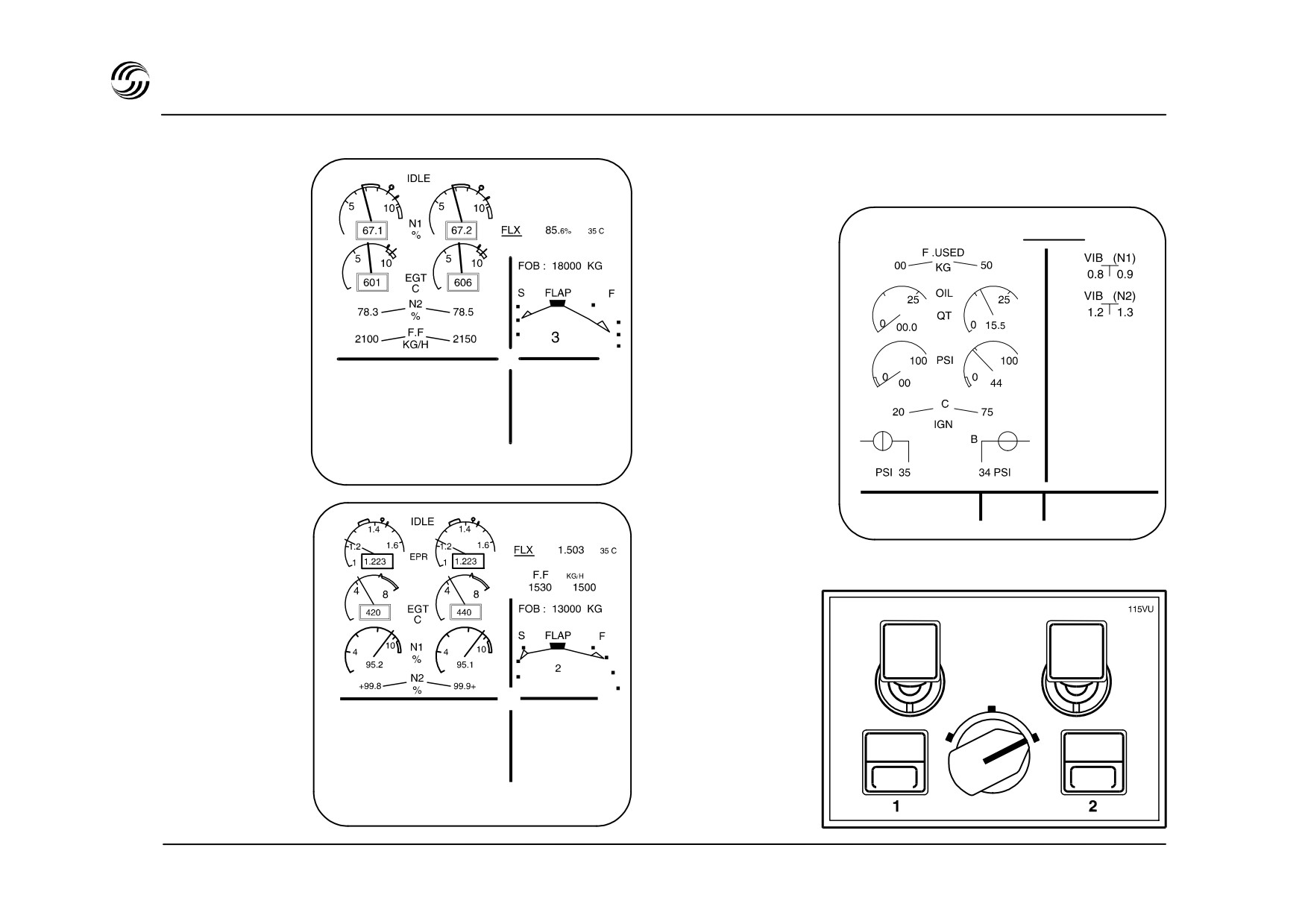
A319/A320/A321 engine controls indications (CFM56) on ECAM upper DU
Appears when both
Transient N1 during ATS operation
engines at IDLE (*)
corresponding to FMGC demand to
go to N1 target
Symbol corresponding to
Max N 1
the thrust lever position
Max permissibleN1
IDLE
N1 actual
Flex temperature
(entered through MCDU)
Exhaust gas
N 1 rating limit
temperature
S
FLX
F
3
SEAT BELTS
FOB : 18000 KG
NO SMOKING
Thrust limit mode
* Basic on A319/A321
STL 945.7136/97
8.12
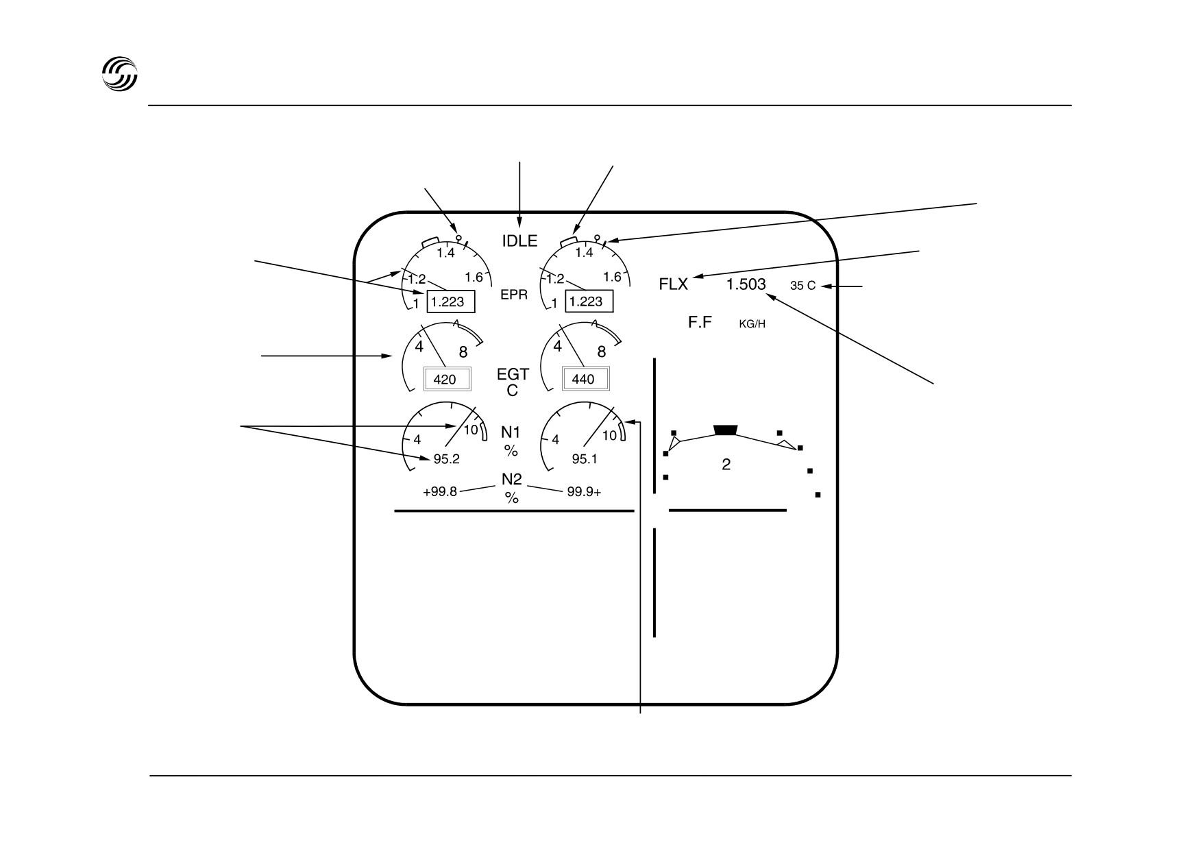
A319/A320/A321 engine controls indications (IAE 2500) on ECAM upper DU
Appears when both
engines at IDLE (*) Transient N1 during ATS operation
Symbol corresponding to
corresponding to FMGC demand to
the thrust lever position
go to EPR target
Max EPR
Thrust limit mode
Actual EPR
Flex temperature
(entered through MCDU)
1530
1500
Exhaust gas
temperature
FOB : 13000 KG
EPR rating limit
S FLAP F
Actual N1
F
SEAT BELTS
NO SMOKING
Max permissible N1
* Basic on A319/A321
STL 945.7136/97
8.13
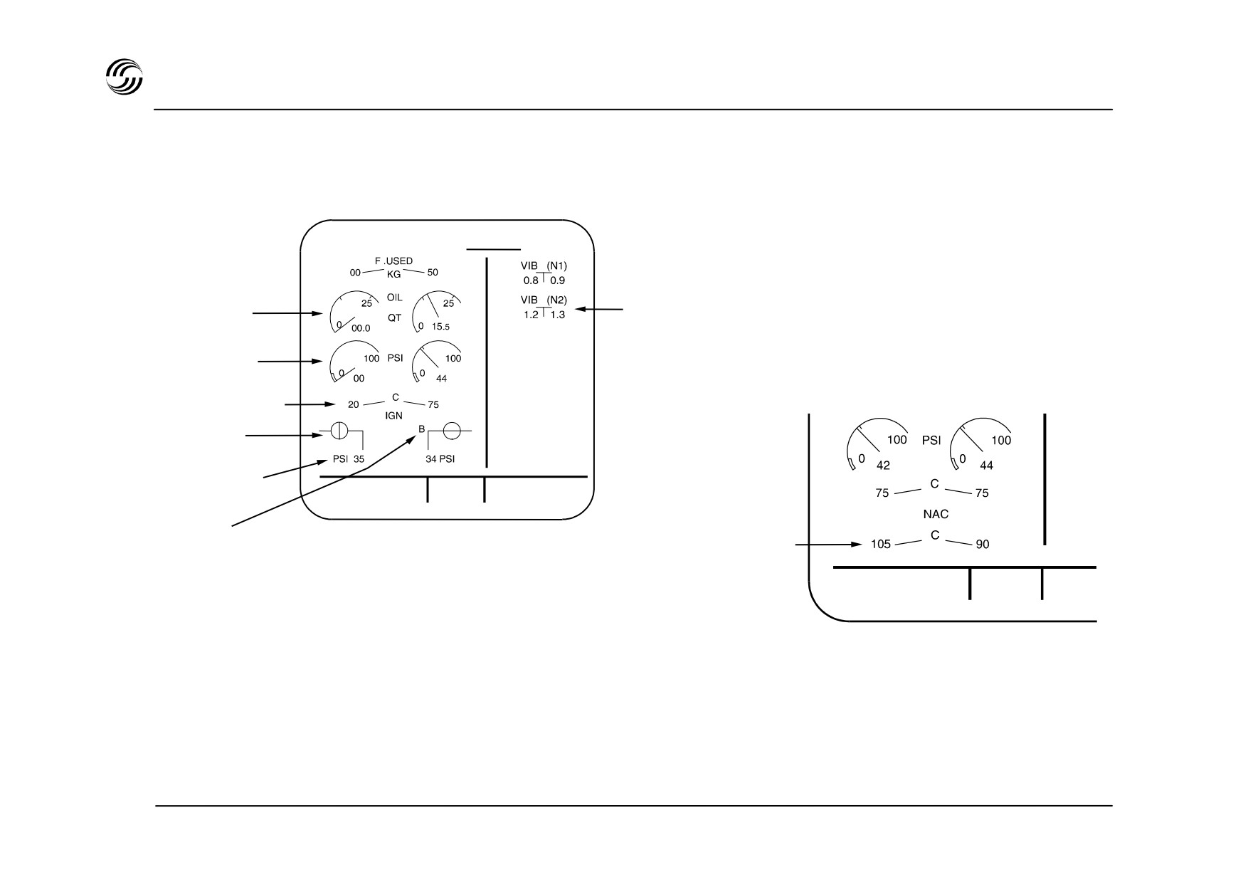
A319/A320/A321 EIS independent : after “clear” action
Start configuration
Oil quantity
Engine vibration
Oil pressure
After start configuration
°
Oil temperature
Start valve
position
Engine bleed
°
TAT + 19 °C
G.W. 60300 kg
pressure
23 H 56
SAT + 18 °C
Selected
°
Nacelle temperature
ignition
TAT + 19 °C
G.W.
SAT + 18 °C
23 H 56
STL 945.7136/97
8.14
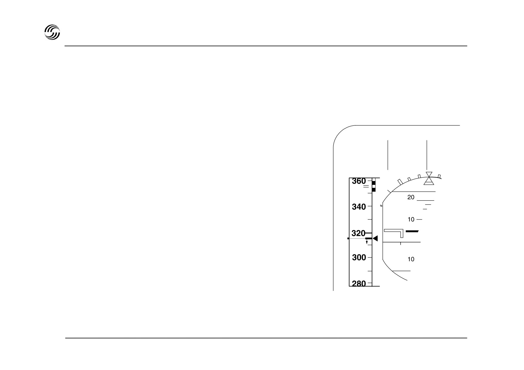
A319/A320/A321 engine controls indications on PFD : FMA
The following indications may appear on the PFD Flight
Mode Annunciator (FMA), in upper left corner :
ASYM
:
Only one thrust lever is set to CLB or
MCT position,
FINAL APP NA
CLB
:
Flashing when aircraft above thrust
reduction altitude and thrust levers
ASYM
not in CLB notch,
MCT
:
Flashing in case of engine failure if the
non-affected thrust lever is not set at
MCT,
A-FLOOR :
-floor condition encountered,
TOGA LK : When leaving -floor condition and
thrust still at MTO
STL 945.7136/97
8.15


A319/A320/A321 engine controls - thrust reverse
Reverser deployment selection by positioning thrust
lever into reverse area and by acting on independent
locking levers.
Thrust lever position below rev. idle modulates reverse
power.
Automatic engine idle setting in case of reverser
malfunction.
Automatic max. reverse power limitation versus
ambient conditions with full rearward thrust lever
position.
Display of reverser status on ECAM upper DU.
STL 945.7136/97
8.17
A319/A320/A321 engine controls - start procedure
Lower ECAM DU
CFM
°
°
SEAT BELTS
CTR TK FEEDG
NO SMOKING
°
Upper
ECAM DU
TAT + 19 °C
G.W. 60300 KG
23 H 56
SAT + 18 °C
°
IAE
MASTER 1
MASTER 2
°
ON
ON
ENG
ENG
1
2
OFF
OFF
MODE
NORM
SEAT BELTS
CTR TK FEEDG
IGN
CRANK
START
NO SMOKING
FIRE
FIRE
FAULT
FAULT
STL 945.7136/97
8.18

A319/A320/A321 engine controls - start procedure
z Engine mode selection
IGN/START
ECAM ENG page is automatically displayed on lower ECAM.
- Pack valves close (CFM engines)
z MASTER switch
ON
- Start valve opens
- APU RPM increases
- N2 increases
- Oil pressure increases
- Pack valves close (IAE engines)
Depending on N2 values reached :
- Ignition starts
- HP fuel valve opens
When sufficient N2 value is reached :
- Start valve closes, ignition stops, APU RPM returns to normal, pack valve reopens.
z Main and secondary parameters
CHECK NORMAL
For abnormal conditions on ground :
FADEC automatically controls :
- Start abort in case of hot start, hung start or no light up.
- Automatic engine crank after :
- first start abort for IAE
- any additional start attempts for CFM.
STL 945.7136/97
8.19


9. Auxiliarypower unit
STL 945.7136/97
9.1
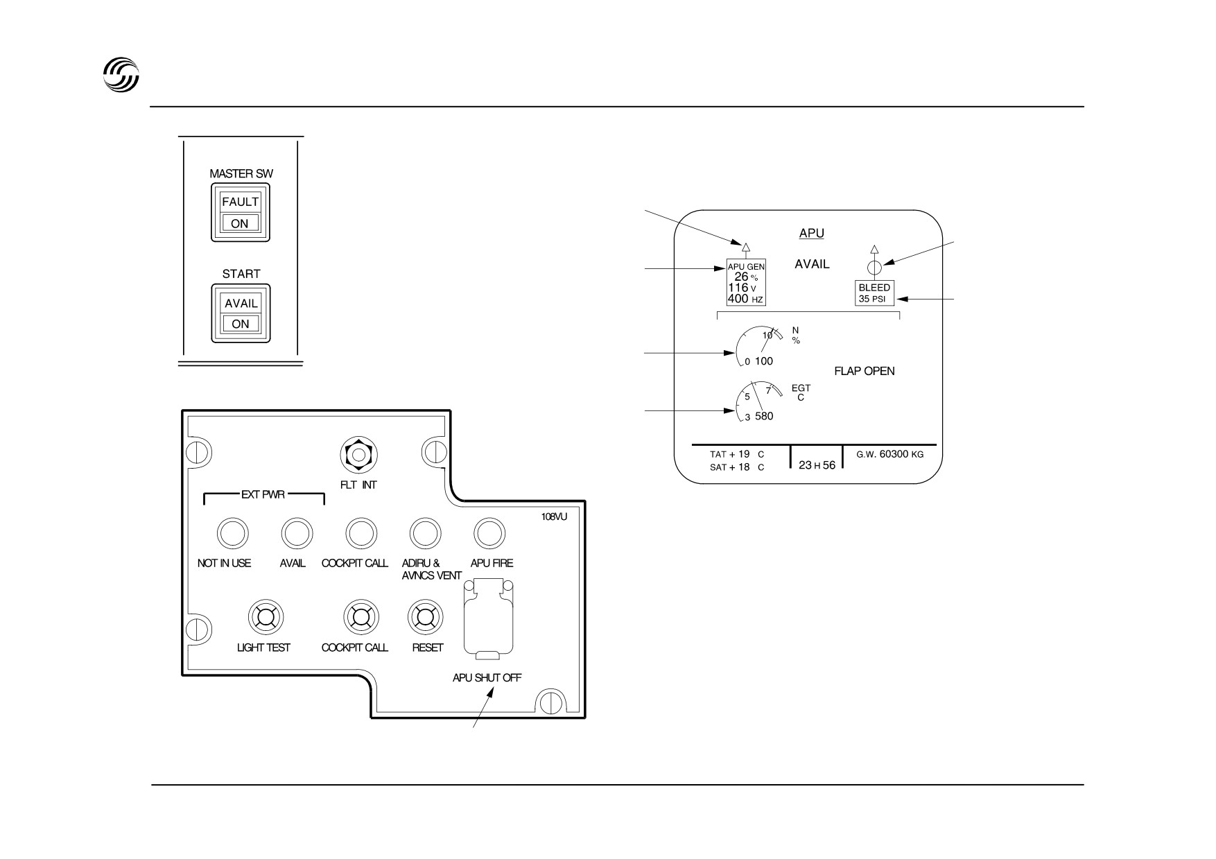
A319/A320/A321 APU - controls and display
ECAM lower display :
APU system page
APU generator
line contactor
APU bleed
Overhead panel
valve position
APU generator
parameters
APU bleed air
pressure
APU speed
External panel (on nosewheel)
°
APU EGT
°
°
APU shut-off push-button
STL 945.7136/97
9.2

A319/A320/A321 APU
z On ground, the APU makes the aircraft independent of
pneumatics and electrical sources by :
- providing bleed air for engine start and air
conditioning systems;
- providing electrical power to supply the electrical
system,
z In flight, provision of back-up power for electrical and
air conditioning systems,
z The APU may be started using either the aircraft
batteries, external power or normal aircraft supply.
The normal flight envelope does not impose any
limitations for starting.
z The APU is automatically controlled by the Electronic
Control Box (ECB) which is mainly acting as FADEC
for monitoring start and shut-down sequences, bleed
air and speed/temperature regulation.
z Control and displays :
- on the overhead panel for APU normal operation
and fire protection
- on the ECAM for APU parameters display
- on the external panel, under the nose fuselage, for
APU shut down.
STL 945.7136/97
9.3


10. Automaticflight system
STL 945.7136/97
10.1
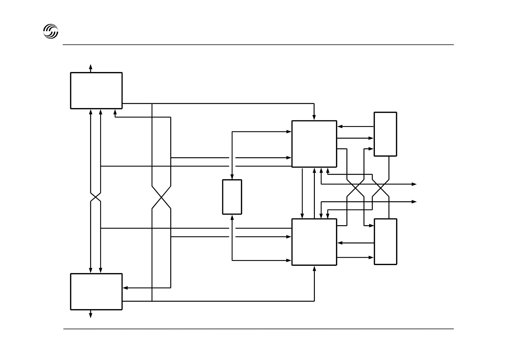
A319/A320/A321 FMGS system architecture
Yaw control
FAC 1
M
C
D
FMGC
U
1
1
FADEC
engine 1
F
C
FADEC
U
engine 2
M
C
FMGC
D
2
U
2
FAC 2
Yaw control
STL 945.7136/97
10.2

A319/A320/A321 FMGS - AFS/FMS integration
z Composed of two Flight Management and Guidance
z The AP/FD achieves either :
Computers
(FMGC), this pilot interactive system
provides :
- automatic control of the aircraft with regard to
speed, lateral path and vertical plan as computed
- flight management for navigation, performance
by the FMGCs,
optimization, radio navaid tuning and information
- manual control of the aircraft with regard to speed
display management,
and vertical plan (selected through FCU), lateral
- flight guidance for autopilot commands (to EFCS),
path (through FMGC or FCU).
flight director command bar inputs and thrust
commands (to FADECs).
z Two FACs (Flight Augmentation Computer) provide :
- rudder commands (yaw damping, rudder trim and
limiting, turn coordination, automatic engine failure
compensation),
- flight envelope and speed computation.
z For operational convenience the FMGS offers two
types of guidance concept :
- managed according to FMGS flight plan data
entered into the Multipurpose Control and Display
(MCDU),
- selected by the pilot through the Flight Control Unit
(FCU).
STL 945.7136/97
10.3
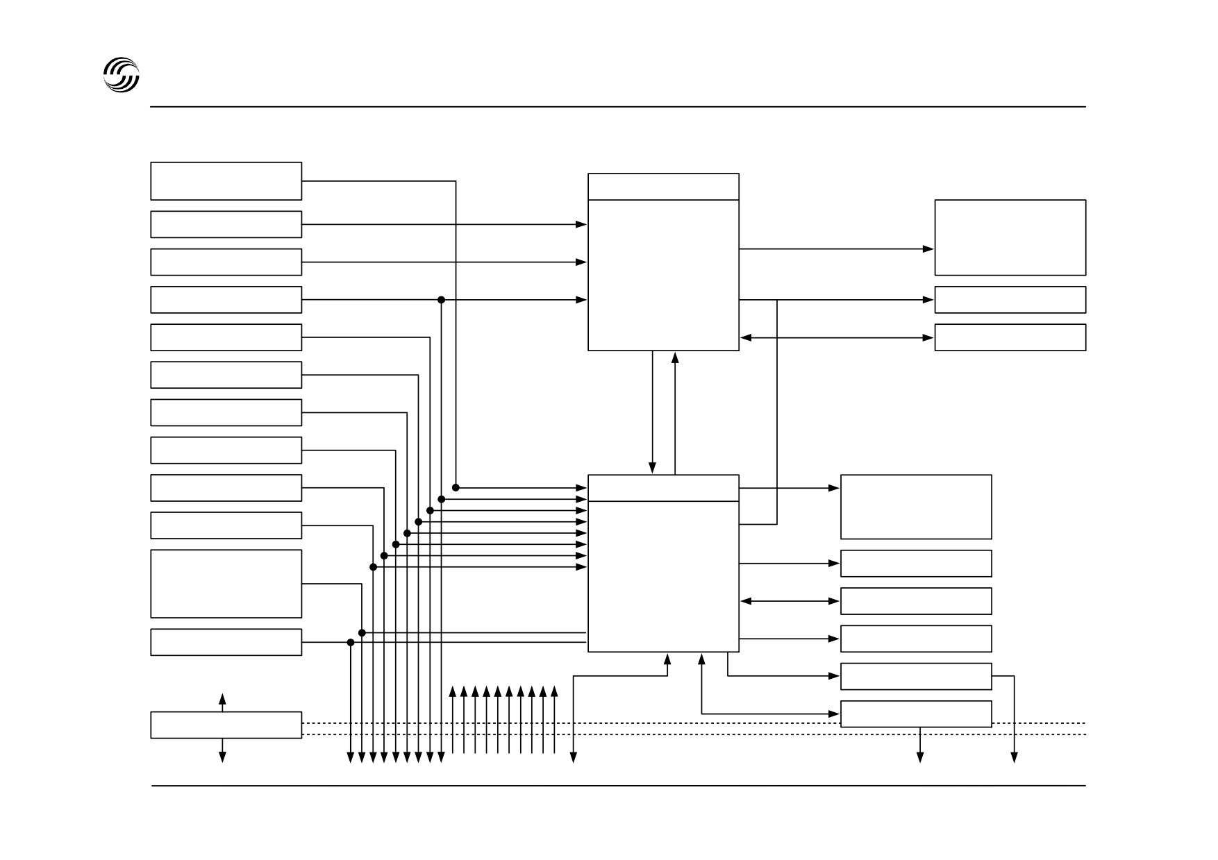
A319/A320/A321 FMGS - system interface
FCDC 1
ELAC/SEC
FAC 1
• Yaw damper
Actuators for :
Landing gear
rudder trim
• Rudder travel
yaw trim damper
limiting
Slats/flaps
rudder travel
• Rudder trim
ADIRS 1
• Flight envelope
EIS (DMC 1, 2,
3)
protection
ILS 1
• Yaw AP
CFDIU
RA 1
VOR 1
DME 1
Clock
FMGC 1
Radio navigation
auto tuning
Fuel
• AP/FD/ATS
• Cruise and land
Data
modes
EIS (DM 1, 2, 3)
base
• Lateral nav.
loader
ELAC-SEC
• Vertical nav.
• Performance
FADEC 1
FWC 1, 2
To FAC 1
To system
1
ECU
and FMGC 1
Side
1
MCDU
ADIRS 3
Side 2
To FAC
2
FMGC 2
To system
2
STL 945.7136/97
10.4
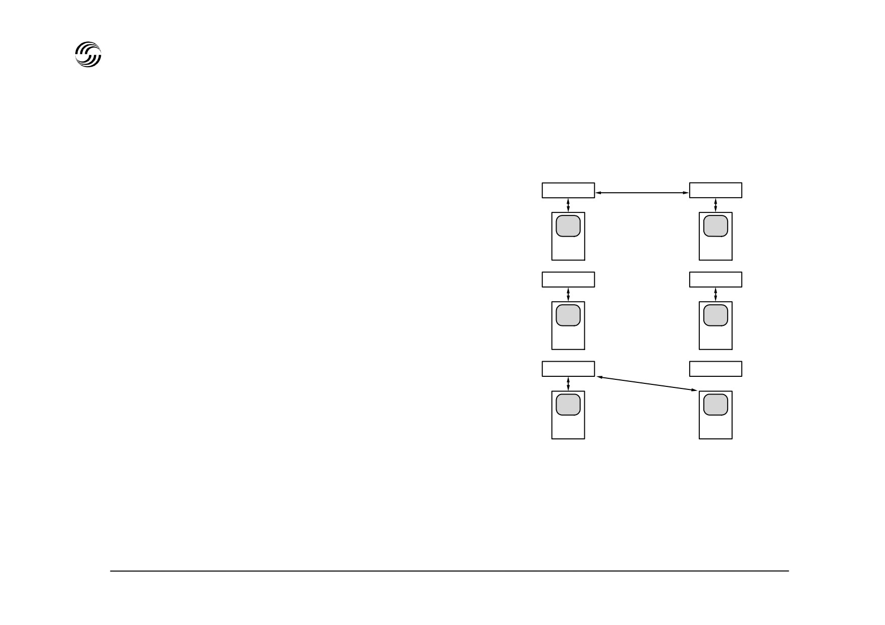
A319/A320/A321 FMGS - system redundancy
Two FMGCs associated to two MCDUs provide a
redundant configuration.
Crosstalk
FMGC 1
FMGC 2
z
Normal mode operation : dual mode
buses
- Each FMGC makes its own computation
- One FMGC is MASTER - the other one is SLAVE
MCDU
MCDU
- Both MCDUs act independently (entries are
automatically recopied on the other MCDU and
FMGC 1
FMGC 2
applied to both FMGCs)
z
Independent mode
MCDU
MCDU
- Automatically operative if mismatch between
FMGCs
FMGC 1
FMGC 2
- Independent operation of FMGCs with associated
MCDUs. (Data insertion and display related to the
side concerned).
- One FMGC remains master.
MCDU
MCDU
z Single mode
- One FMGC fails
- Either MCDU can be used to enter or display data
related to the remaining FMGC.
STL 945.7136/97
10.5
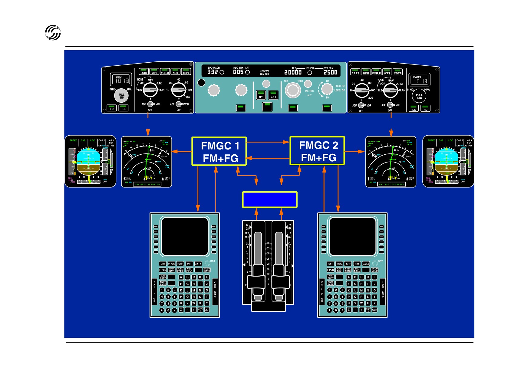
A319/A320/A321 FMGS crew interface
ND 1 control
FCU
ND 2 control
PFD 1
ND 1
ND 2
PFD 2
Guidance Navigation
Navigation Guidance
FADEC
display
display
display
display
MCDU 1
Thrust levers
MCDU 2
STL 945.7136/97
10.6

A319/A320/A321 FMGS crew interface
z Two MCDUs on the central pedestal provide long-term
interface between the crew and FMGCs in terms of :
- flight plan definition and display
- data insertion (speeds, weights, cruise level, etc)
- selection of specific functions (direct to, offset,
secondary flight plan).
z One FCU on the central glareshield to provide short-
term interface between crew and FMGCs.
z Two thrust levers linked to the FMGCs and FADECs
provide autothrust or manual thrust control selection to
the crew.
z Two PFDs and two NDs provide visual interface with
flight management and guidance related data such as :
on PFD :
- FMGS guidance targets,
- armed and active modes
- system engagement status
on ND :
- flight plan presentation,
- aircraft position and flight path,
- navigation items (radio navaid, wind).
STL 945.7136/97
10.7
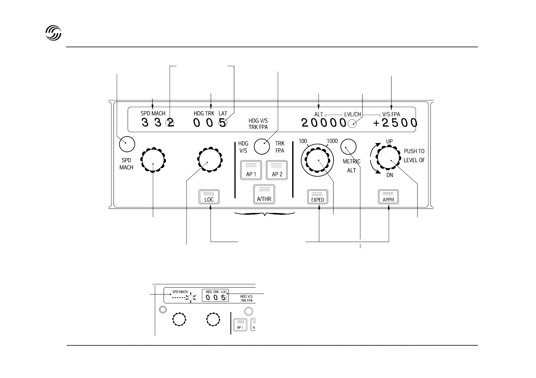
A319/A320/A321 FMGS flight guidance
Speed / Mach
Auto control
Vertical speed /
Commutation
white lights
Flight Path angle
Altitude Auto control
window
Heading / track
Speed / Mach
window
window white lights
window
AP / A / THR
Altitude
V / S or FPA
SPD or TRK
engagement
selection
selection
selection
Mode engagement
HDG or TRK
Control the display of selected altitude
selection
(in meters) on lower ECAM (permanent data)
z Managed guidance parameter window is dashed and auto control illuminated.
Managed speed guidance
Lateral selected guidance
STL 945.7136/97
10.8

A319/A320/A321 FMGS flight guidance
z
The FCU is the main crew interface for short-term
guidance with a single rule for the various control
knobs :
- pull + rotate = pilot input
- push = return to FMGS control.
z
As an example, a change of altitude can be achieved
by a double action on the FCU :
- either by selection of a new altitude through the
FCU selector and validation of this new
altitude pushing (management guidance)
this knob.
- or by
selection of a V / S through the FCU
selector and validation of this new V
/ S by pulling this knob.
z
Actions on the FCU are displayed on the FCU as well
as on the PFD in the dedicated FMA
(Flight
Management Annunciator) part.
STL 945.7136/97
10.9

A319/A320/A321 FMGS flight management
Flight plan stringing
Navigation
Flight plan definition by company route or city pair.
Automatic guidance along flight plan from take-off to
approach.
Departure and arrival procedures including associated,
speed/altitude/time constraints.
Aircraft position determination.
Flight plan revision
(offset, DIR, TO, holding pattern,
Aircraft position referenced to the flight plan.
alternative flight plan activation,…)
Automatic VOR/DME/ILS/ADF selection.
Secondary flight plan creation similar to primary flight plan.
IRS alignment.
Ground speed and wind computation.
Optimum radio and inertial sensor mixing.
Provision for GPS and MLS.
STL 945.7136/97
10.10

A319/A320/A321 FMGS performance management
z Flight plan optimization, through the performance data
base, in terms of :
- optimum speeds
- optimum altitudes.
z The computations are based on :
- flight conditions (cruise level, weights, center of
gravity, meteorological data)
- cost index
- speed entered on the FCU or given in the flight
plan.
z Performance predictions :
- time, altitude, speed at all waypoints
- estimated time of arrival, distance to destination,
estimated fuel on board at destination.
z Advisory functions :
- fuel planning
- optimum altitudes and step climb.
z Full vertical guidance related to flight plan predictions
from initial climb to approach.
STL 945.7136/97
10.11
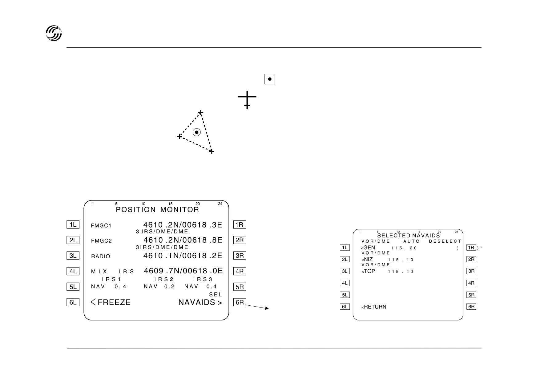
A319/A320/A321 FMGS - lateral navigation
Radio or GPIRS position (if GPS primary installed)
FMGC position
IRS 1
Mix IRS
IRS 2
Mix IRS = mean IRS
IRS 3
GIPRS = GPS position integrity verified against IRS position
To see the
navaids used for
radio position
STL 945.7136/97
10.12

A319/A320/A321 FMGS - lateral navigation
z Position computation :
The navigation modes may be :
- before flight, the three IRSs are aligned on airfield
En route :
or gate position. (manually or via database)
- at take-off, the position is automatically updated to
IRS - GPS (if GPS installed)
the runway threshold
IRS - DME
- in flight, position updating is computed using GPS if
IRS - VOR/DME
installed, and radio navaids (DME,VOR, ILS)
IRS only
The FMGC position depends upon the IRS’s mean,
In approach :
the GPS and the radio position.
IRS - GPS (if GPS installed)
z
Navigation mode selection :
IRS - DME
IRS - VOR/DME
- if the aircraft is equipped with GPS primary, the
IRS - ILS/DME
FMGC uses GPIRS position in priority
- if the GPIRS position is not available or if the
aircraft is not equipped with GPS primary,
depending upon availability of navaids and sensors,
FMGC automatically tunes the best navaids to
compute the most accurate position.
STL 945.7136/97
10.13
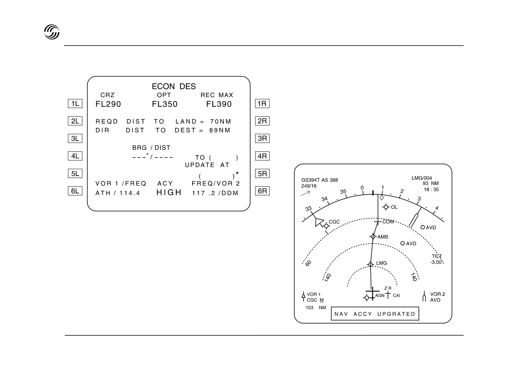
A319/A320/A321 FMGS - lateral navigation
MCDU
ND
STL 945.7136/97
10.14

A319/A320/A321 FMGS - lateral navigation
z FMGC provides the crew with lateral position and its
associated accuracy criteria which depend upon :
- FMGC Error Position Estimate (EPE)
- zone currently flown (en route, terminal, approach)
- Airworthiness Authorities Accuracy Requirements
(AAAR)
z If EPE AAAR then HIGH is displayed on MCDU and
the computed positions may be used without
restriction.
z If EPE > AAAR then LOW is displayed on MCDU and
the position must be cross-checked with raw data
(ADF/VOR needles, DME reading).
z Each time HIGH (or LOW) reverts to LOW (or HIGH)
the message NAV ACCY DOWNGRADED
(or
UPGRADED) is displayed on NDs and MCDUs.
STL 945.7136/97
10.15
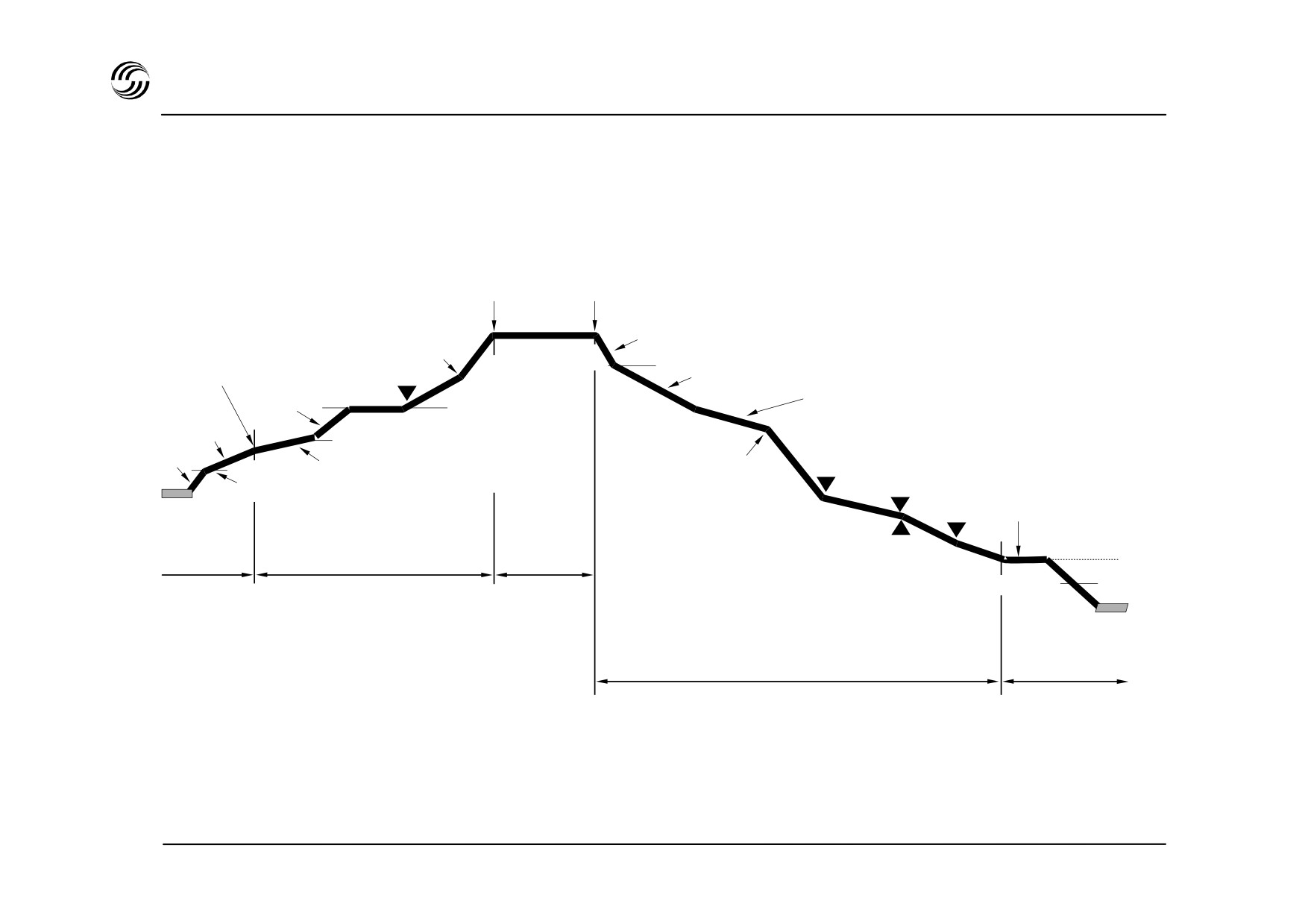
A319/A320/A321 flight deck - main features
Top of climb Top of descent
Cruise
ECON
ECON CRZ
cruise Mach
Transition
Mach
Mach/speed
Level segment
ECON DES
Acc. Alt.
Transition from
speed to Mach
speed
Deceleration at 500ft/min
Climb
average
V2+10
Acceleration by
“At or below”
V2+10
Speed limit
energy sharing
constraint
Thrust
reduction
“At or below”
Deceleration
Take-off
constraint
in flight level
runway
Alt.
“At”
Glideslope
constraint
Take-off
Climb
Cruise
100ft : VAPP
Runway
Descent
Approach
STL 945.7136/97
10.16

A319/A320/A321 FMGS - vertical profile
z Take-off :
z Approach :
From DECEL point a deceleration allows configuration
SRS control law maintains V2
+ 10 up to thrust
changes in level flight.
reduction altitude where max climb thrust is applied.
V2 + 10 is held up to acceleration altitude (ACC LT).
Approach phase is planned to reach approach speed
at 1000ft above ground level.
z Climb :
Energy sharing is applied for acceleration (70% thrust)
and for altitude (30% thrust) from ACC ALT up to first
climb speed. Max climb thrust is kept
- Altitude
constraints are taken into account.
z CRZ :
Steps may exist and/or may be inserted.
z Descent :
Top of Descent (T/D) is provided on ND.
From T/D down to the highest altitude constraint,
ECON descent speed is supposed to be held on
elevator and IDLE + on thrust.
Then, if this status can no longer be kept, geometric
segments will be followed between the constraints.
STL 945.7136/97
10.17

A319/A320/A321 FMGS - AP / FD modes
Guidance
Managed
Selected
z
NAV and APP NAV
z
HDG - TRK
z
APPR
z
LOC
Lateral
z
RWY
z
RWY TRK
z
G.A. TRK
z
CLB
z
OP CLB
z
DES
z
OP DES
Vertical
z
SRS (TO / GA)
z
Expedite (towards altitude
z
G/S
selected on FCU but
z
FLARE
managed speed)
z
FINAL
z
ALT
z
V / S - FPA
z
F. PLN reference
z
FCU selected
Speed
(ex. : optimum)
z
Expedite
STL 945.7136/97
10.18

A319/A320/A321 FMGS - AP / FD modes
z Managed guidance
z Selected guidance
Take-off :
Lateral :
- RWY
: automatic runway axis follow up
- HDG/TRK
: selected on FCU
through ILS use
- RWY. TRK : follow up of the memorized runway axis
Vertical :
- SRS
: pitch guidance to maintain V2 + 10
- OP CLB/OP DES : open modes for level changes
Climb/Cruise/Descent :
with a fixed thrust and speed
held on elevator
- NAV
: lateral guidance along the defined F.PLN
- EXPED
: level change with maximum
- CLB/DES
: vertical guidance with respect of all the
climb/descent
F.PLN defined constraints
- ALT
: altitude capture and hold
- APP NAV
: lateral guidance along a defined non
- V/S-FPA
: vertical speed or flight path
precision approach
angle track
Approach and landing :
- APPR
: ILS approach (ILS beams capture and
track) and non precision approach
- LOC
: LOC use only (capture and track)
- FLARE
: automatically performed around 30ft
- FINAL
: vertical guidance along a defined non
precision approach
STL 945.7136/97
10.19
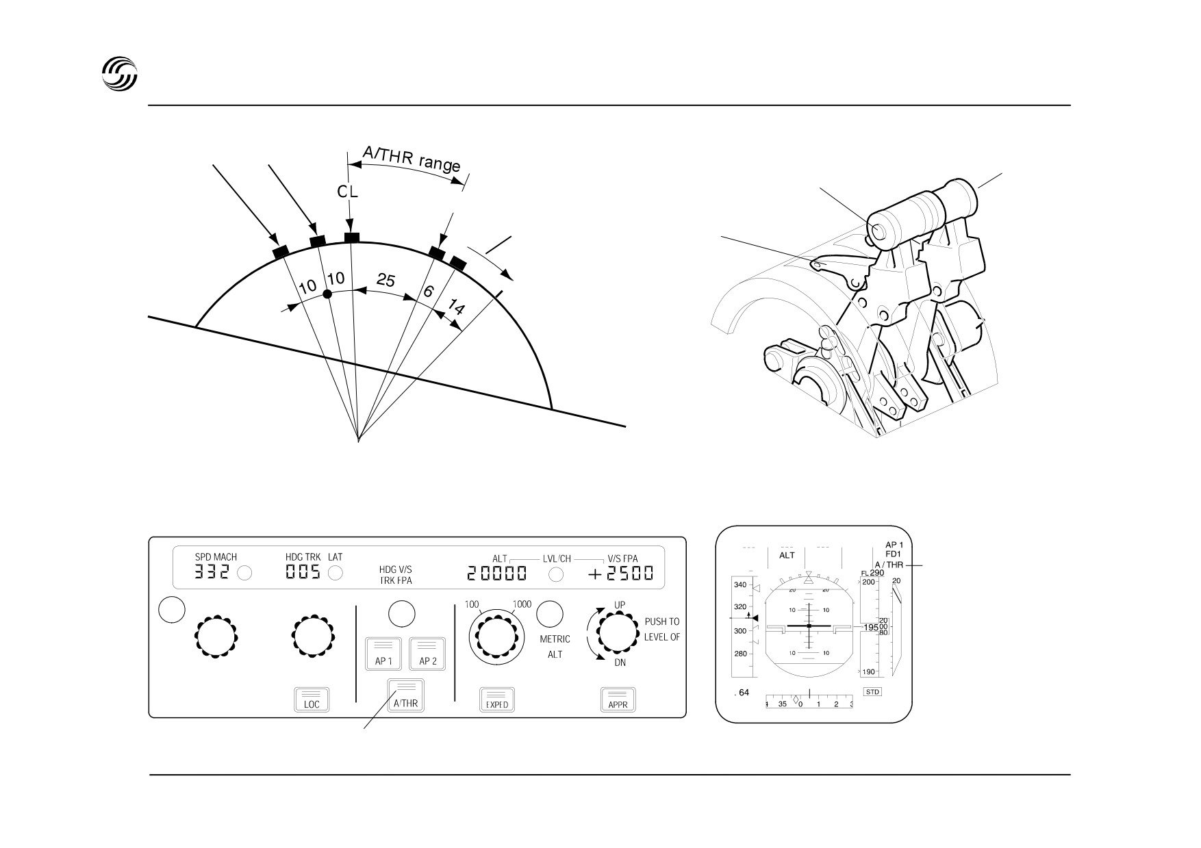
A319/A320/A321 ATS - controls and display
T.O
FLX T.O.
Instinctive
G.A MCT
disconnect
Thrust levers
pushbutton
Idle
Reverse unlock
Reverse
FCU
PFD
Displayed
- Cyan when engaged
- White when active
Illuminated greed when
A/THR engaged
STL 945.7136/97
10.20

A319/A320/A321 FMGS - autothrust function
z Autothrust (A/THR) is part of FMGC
z No mechanical linkage between levers and engines.
Thrust levers position is measured and transmitted to
the FADEC in digital form.
z Autothrust :
- either ensures thrust control depending upon
AP/FD modes (if these are engaged)
- or manages thrust to hold the current target speed
(if no AP/FD engaged)
- thrust control is achieved without moving the levers.
z A/THR engagement status and thrust limit mode
depend upon thrust lever angle (TLA).
Thrust limit selection and computation are made by
the FADEC.
z
5 positions are fitted within the levers position range.
STL 945.7136/97
10.21
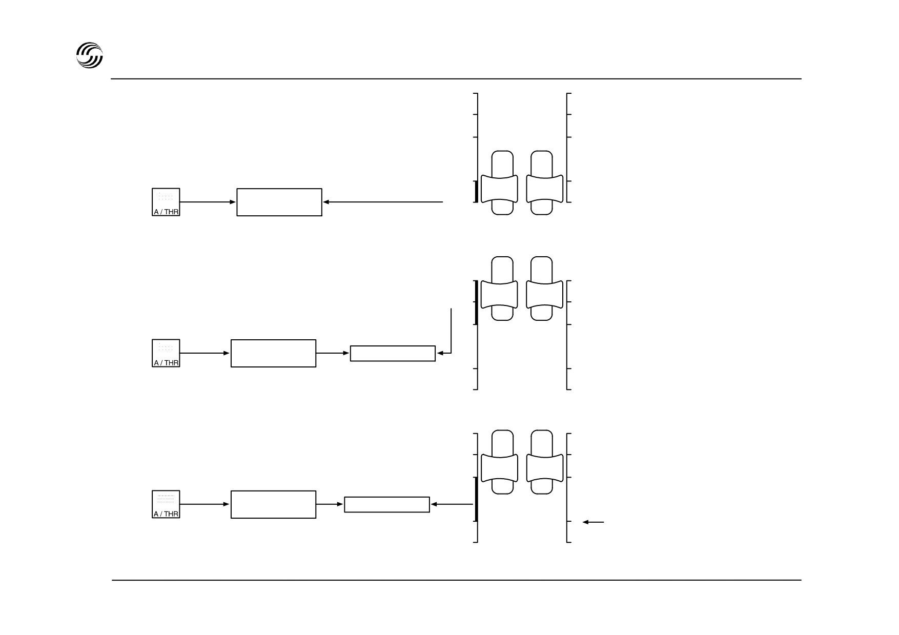
A319/A320/A321 FMGS - autothrust function
TO / GA
TO / GA
FLX / MCT
FLX / MCT
CL
CL
0
0
Not engaged
REV
REV
Thrust levers
TO / GA
TO / GA
FLX / MCT
FLX / MCT
CL
CL
Engaged
Not active
0
0
REV
REV
Thrust levers
TO / GA
TO / GA
FLX / MCT
FLX / MCT
CL
CL
Engaged
Active
0
0
Both thrust levers at idle result in
REV
REV
A/THR disengagement
Thrust levers
STL 945.7136/97
10.22

A319/A320/A321 FMGS - autothrust function
Operational rules
z A/THR can be engaged :
- manually by pressing the A/THR pushbutton
- automatically, by setting the thrust levers at TO/GA
or FLEX position.
z A/THR is then activated if thrust levers are set between
CL (included) and IDLE (excluded) gates.
In this case, commanded thrust is limited by TLA
(except ALPHA-FLOOR activation).
z A/THR not active (A/THR p/b on FCU extinguished)
and
Pressing A/THR p/b on FCU activates A/THR
thrust levers within A/THR range
z A/THR can be disengaged by :
Depressing the instinctive disconnect P/B on the levers
or depressing the illuminated A/THR P/B on FCU or
setting both thrust levers in IDLE gate.
STL 945.7136/97
10.23
A319/A320/A321 FMGS - autothrust function
z If the levers are in CLB gate and A/THR is disengaged
then :
- thrust is frozen at its current value until thrust levers
are moved out of the gate.
THR LK amber message appear on PFD.
z If the levers are not in CLB gate when A/THR is
disengaged then :
- thrust is not frozen but is set according to the lever
position.
z Engagement of A/THR mode is automatic according to
AP/FD engaged mode :
AP/FD mode
ATS mode
V/S-FPA
SPD/Mach
ALT (ACQ/HOLD)
Expedite
Thrust
Descent/Climb
Thrust/SPD/Mach
SPD/Mach
Thrust
final descent
SPD
Approach
glide
SPD
flare
Retard
TO/ GA
ATS Armed
STL 945.7136/97
10.24

A319/A320/A321 FMGS - autothrust function
Autothrust operation
z Take-off performed :
- in TO limit mode with levers in TO.GA notch
- in FLEX TO limit mode with levers in FLX TO/MCT
detent provided a FLX temperature has been entered
on MCDU (take-off page). Lowest FLX TO thrust is
automatically limited to CL thrust.
Note : In both cases, this manoeuvre also engages
the flight director TO mode.
z Once out of take-off (or go around), the nominal phases
in autothrust are always :
This is indicated to
- CL gate in twin engine situation
the crew by a CLB
or MCT message
- MCT gate in single engine situation
on PFD
- One lever in CL gate and the other out of this gate (in
twin-engine operation) causes the engines to be
regulated differently. ASYM amber message appears
on PFD
z In approach, A/THR control depends on type of
approach
(ILS, non precision) and vertical mode
selected on FCU.
z If Alpha floor function is activated, TO/GA thrust is
automatically applied whatever the lever position and
A/THR status are.
STL 945.7136/97
10.25


11. Environmentalcontrol system
STL 945.7136/97
11.1

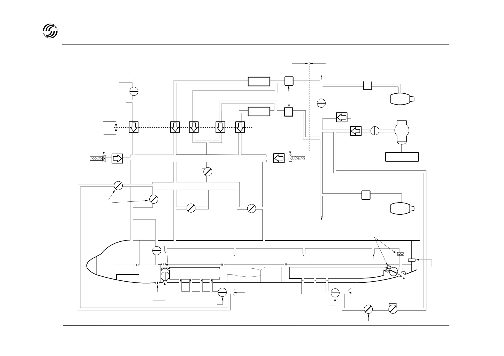
A319/A320/A321 ECS - system schematic
Air conditioning
Pneumatic
ATA 21
ATA 36
Bleed air
To wing
regulation
Emergency ram air
Pack 2
Pack
valves
Eng 2
LP ground connection
Cross-bleed valve
Non-
Non-
Pack 1
return
return
HP ground-connection
Air generation
valve
valve
APU
Air distribution
APU bleed
Recirculation fan
Recirculation fan
valve
Filter
Mixer unit
Non-return valve
Filter
APU control unit
Pressure
Non-
regulating valve
return
Bleed air
valve
Hot manifold
regulation
Trim air
Eng 1
valves
Trim air
Trim air
valves
valves
To wing anti ice
Extraction
fan
Flight
Extraction
deck
fan
Fwd zone
Aft zone
Electr
Safety
Fwd cargo com.
Aft cargo comp.
comp.
valve
Cabin
Electr. vent
Outflow
ambient air
Venturi
valve
Isolation valve
Isolation valve
Trim air valve
Pressure regulating valve
STL 945.7136/97
11.3
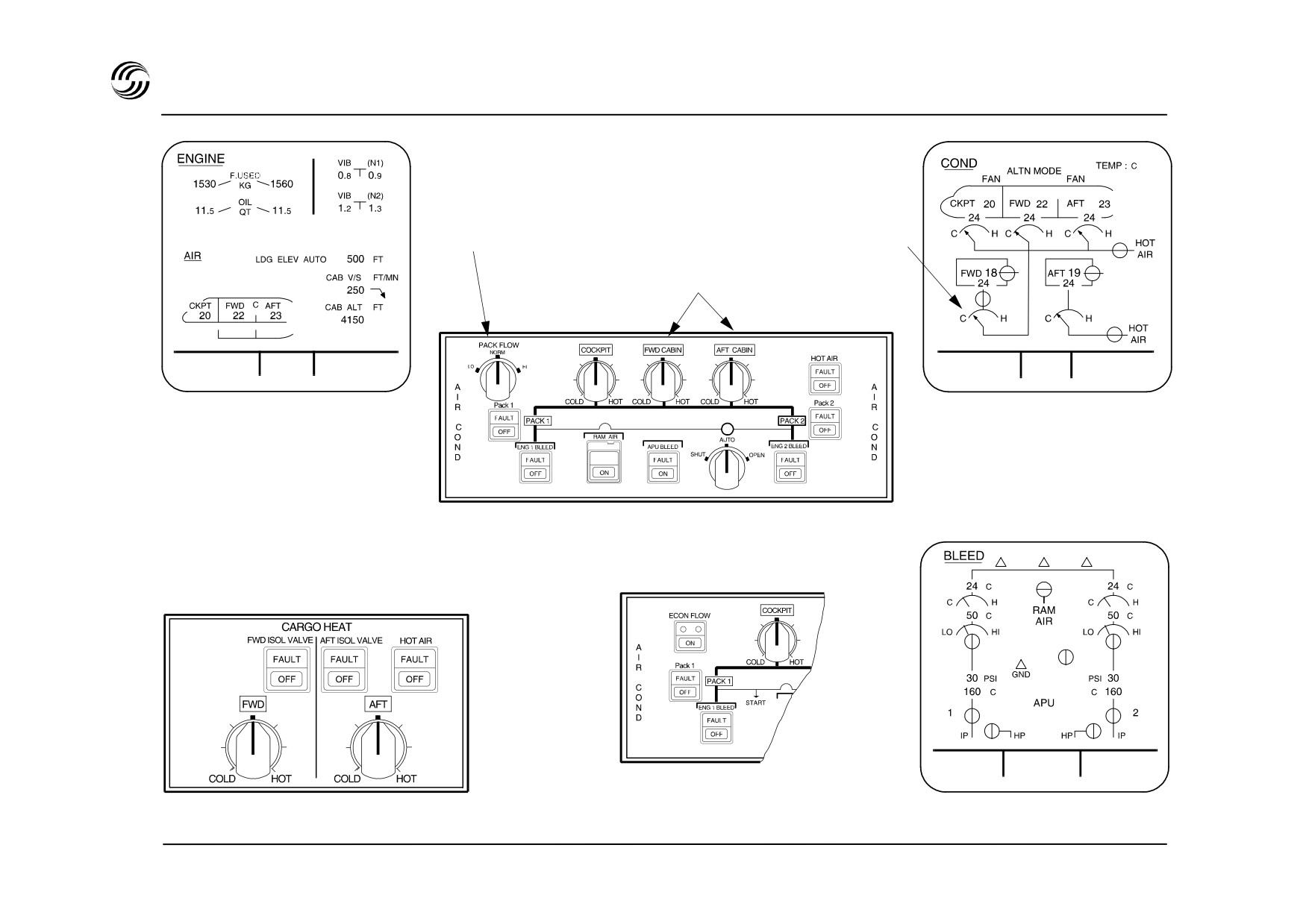
A319/A320/A321 ECS - temperature and flow control
Space optional
Variable flow selector
FWD + AFT cargo heat
Automatic temperature control selectors
Flight deck
TAT + 19°C
G.W. 60300 KG
TAT + 19 °C
G.W. 60300 KG
SAT + 18 °C
23 H 56
23 H 56
SAT + 18 °C
System display :
System display :
Cruise page
CON system page
System display :
A319/A320
BLEED system page
Cargo heat - optional
A321
TAT + 19 °C
G.W. 60300 KG
SAT + 18 °C
23 H 56
STL 945.7136/97
11.4

A319/A320/A321 ECS - air conditioning - pneumatic - general
Air conditioning
Pneumatic
Continuous air renewal and temperature regulation in three
High pressure air is supplied for air conditioning, air
independently controlled zones (cockpit, forward cabin, aft
starting, wing anti-ice, water pressurization, hydraulic
cabin).
reservoir pressurization.
Downstream both packs, a dedicated unit mixes cold air
System operation is electrically monitored by two Bleed
with recirculated cabin air for distribution to the three
Monitoring Computers
(BMC), and is pneumatically
zones.
controlled.
Optimized air temperature is obtained by adding engine
A leak detection system is provided to detect any
hot air to mixing unit air via three trim air valves.
overheat in the vicinity of the hot air ducts.
Cabin and pack temperature regulation are achieved by a
zone controller and two pack controllers.
STL 945.7136/97
11.5
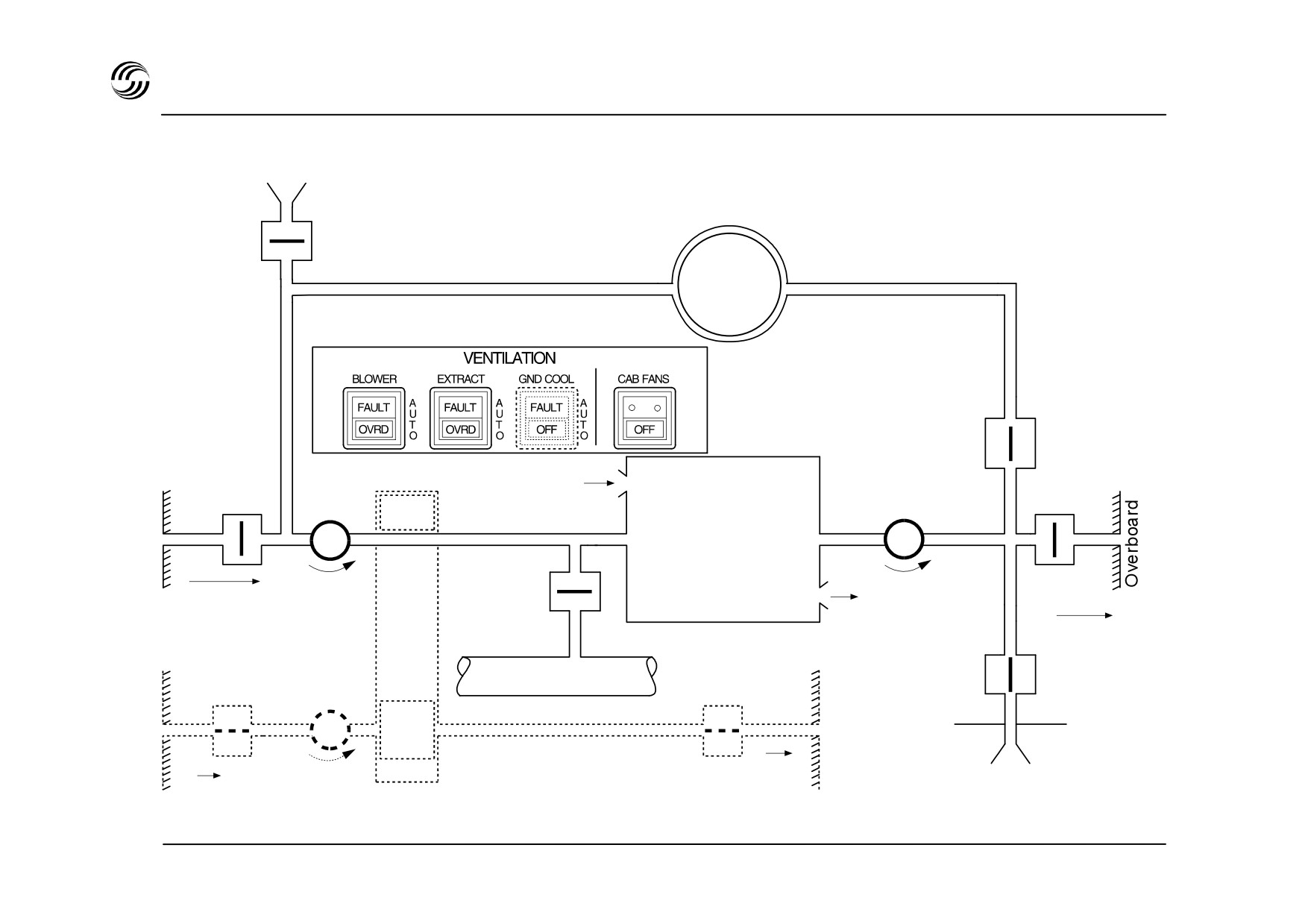
A319/A320/A321 ECS flight deck - main features
Avionics bay
Skin heat
Open if T > 35°C in flight
exchanger
outlet bypass
Skin heat
valve
exchanger
Skin heat
exchanger
isolation
Inlet
Evaporator
valve
Blower
Extract
valve
fan
fan
Avionics
equipment
Extract
Ground
valve
cooling
unit
Skin heat exchanger
(optional)
Air conditioning
Closed on
inlet
duct
ground
bypass valve
Condensor
Cargo
underfloor
STL 945.7136/97
11.6

A319/A320/A321 ECS - ventilation
Avionics ventilation
Battery ventilation
Provide ventilation and cooling of avionics and electronic
Achieved by ambient air being drawn around the
equipment under digital control (AEVC) and without any
batteries and then vented directly outboard via a venturi.
crew intervention.
Lavatory & galley ventilation
Three main operational configurations are automatically
selected :
Achieved by ambient cabin air extracted by a fan
exhausted near the outflow valve.
•
closed-circuit configuration
(flight) by means of an
aircraft skin heat exchanger and a pair blower and
extract fans,
open-circuit configuration using outside fresh air
•
through opening of inlet and extract valves,
an intermediate flight configuration is selected in case of
•
high temperature, whereby the skin exchanger outlet
bypass valve is opened and the extract valve is
maintained half open.
STL 945.7136/97
11.7
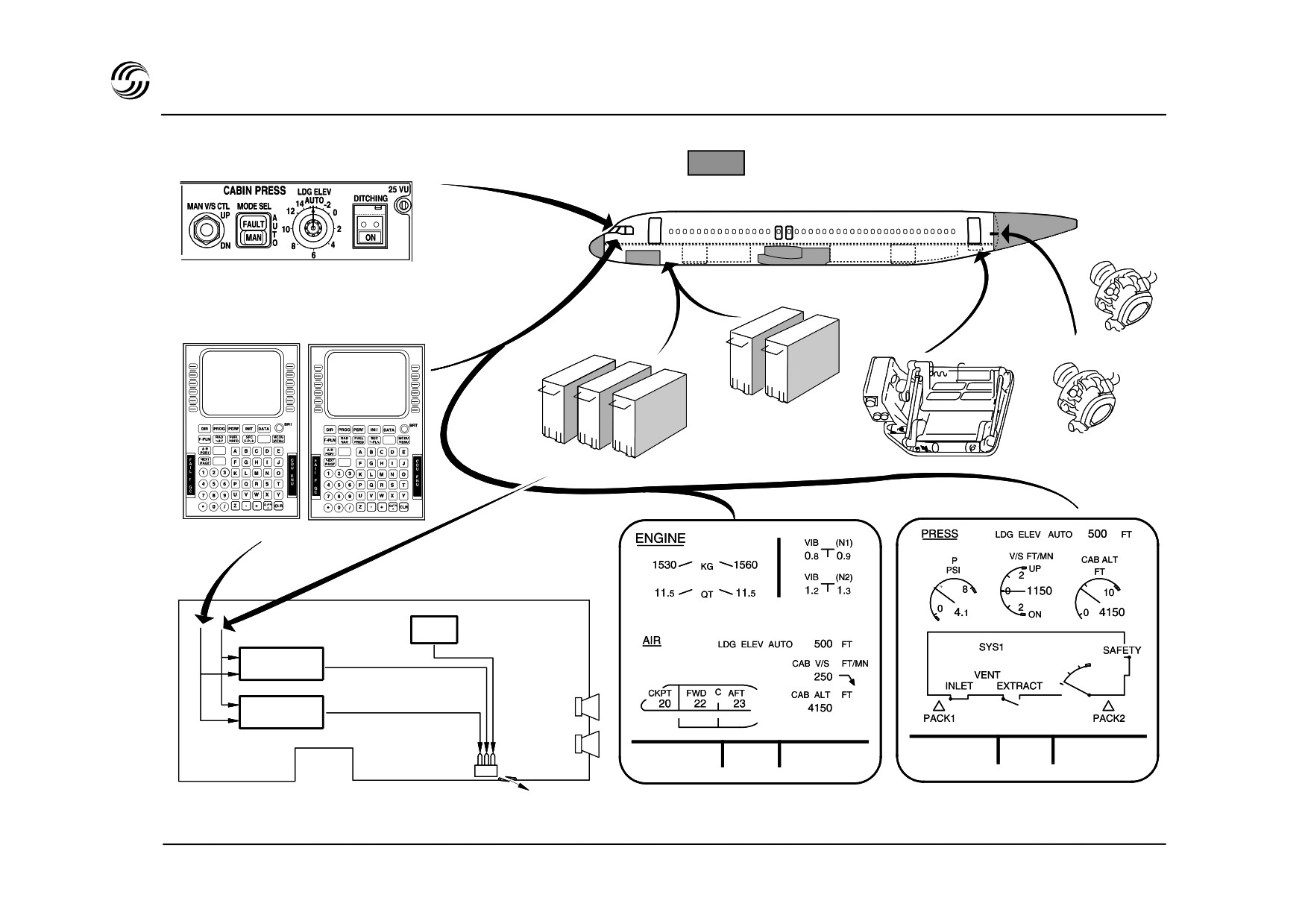
A319/A320/A321 ECS - cabin pressure control
Unpressurized areas
Cabin pressure panel
Outflow
valve
Safety valves
Controllers
ADIRS
FMGS
Manual
control
Cabin pressure
controller 1
Cabin pressure
controller 2
G.W. 60300 KG
TAT + 19 °C
G.W. 60300 KG
3 motors
TAT + 19 °C
and gears
SAT + 18 °C
23 H 56
SAT + 18 °C
23 H 56
Flap type outflow valve
DU 2 CRZ page
DU 2 press system page
STL 945.7136/97
11.8

A319/A320/A321 ECS - pressurization
z The pressurization control system operates fully
automatically without any crew action.
z Dual system with automatic switchover after failure.
Alternative use for each flight. A single outflow valve is
operated by one of three independent electric motors.
Two of these are associated with automatic controllers.
z In normal operation, cabin altitude and rate of change
are automatically controlled from FMGC flight plan data :
- cruise FL, landing field elevation, QNH,
- time to top of climb, time to landing.
z In case of dual FMGC failure, the crew has to manually
select the landing elevation. The cabin altitude varies
according to a preprogrammed law.
z In case of failure of both pressurization system auto-
controllers, the manual back-up mode is provided
through the third outflow valve motor.
STL 945.7136/97
11.9


12. Electronicinstrument system
STL 945.7136/97
12.1
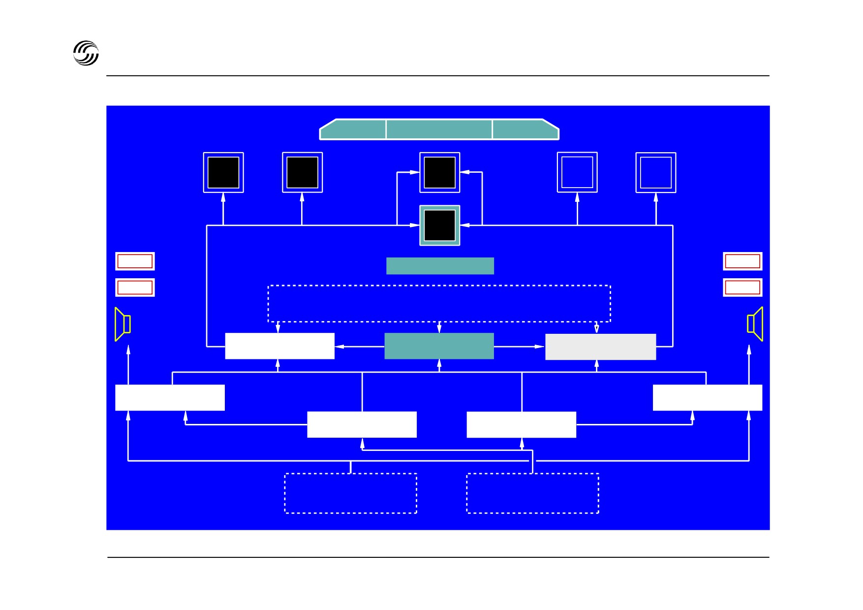
A319/A320/A321 EIS - EFIS/ECAM architecture
EFIS 1
EFIS 2
PFD
ND
ND
PFD
ECAM
1
1
DU 1
2
2
ECAM
DU 2
WARN
WARN
ECAM control panel
CAUT
CAUT
Inputs for EFIS displays : ADIRS, FMGC, FACs , FCU
ADFs, VORs, DMEs, ILS, Ras’ WXRs.
Input for ECAM display : FADEC, FQI, WBCs
DMC 1
DMC 3
DM 2
FWC 1
FWC 2
SDAC 1
SDAC 2
Aircraft systems sensors
Inputs for :
Aircraft systems sensors
Inputs for :
- red warnings
- amber caution
- system pages
- system pages
- flight phases
STL 945.7136/97
12.2

A319/A320/A321 EIS - components
z Six identical (7.25 in x 7.25 in) cathode ray tubes Display
Units (DU), including integrated graphics generator :
- Two primary flight displays + two navigation display
(EFIS)
- One engine warning display + one system display
(ECAM)
z Three Display Management Computers (DMC)
- Generating images to be displayed on PFD, ND and
ECAM Dus
- Digital data link to display units
- No.3 DMC may replace either No.1 or No.2
z Two System Data Acquisition Concentrators (SDAC)
- Acquiring systems data for transmission of
caution/warnings to FWCs and systems condition to
DMCs
- Operations not affected with either SDAC failure.
z Two Flight Warning Computers (FWC)
- Generating alert messages, aural alerts and
procedural messages for display on ECAM
- operations not affected with either FWC failure.
STL 945.7136/97
12.3

A319/A320/A321 EIS - EFIS arrangement
z Primary flight display
- Attitude
- Airspeed
- Altitude/vertical speed
- Heading
- ILS deviation/marker
- Radio altitude
- AFS status (FMA)
z Navigation display, three modes :
- ROSE mode (ILS, VOR or NAV) : aircraft symbol in
screen centre, heading up with radar available
- ARC mode : aircraft symbol in lower part of the
screen, heading up with radar available
- PLAN mode : display centred on selected waypoint,
north up
Note : In ROSE-NAV, ARC and PLAN modes, map data
from FMS are presented
STL 945.7136/97
12.4
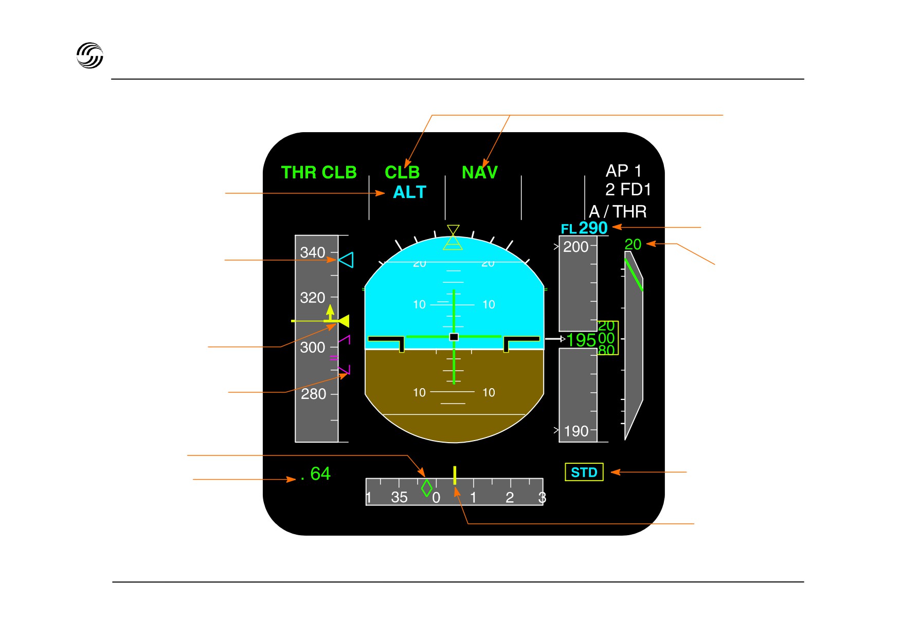
A319/A320/A321 EIS - PFD : climb - FMS guidance
Normal AFS
operational
configuration
ALT acquire armed
Selected altitude
Speed select index
Vertical speed
from FMGS or FCU
2000 ft minute
Actual airspeed
and speed trend
ECON speed range
Aircraft track
Altimeter baro/STD
Mach number
setting display
Magnetic heading
reference
STL 945.7136/97
12.5
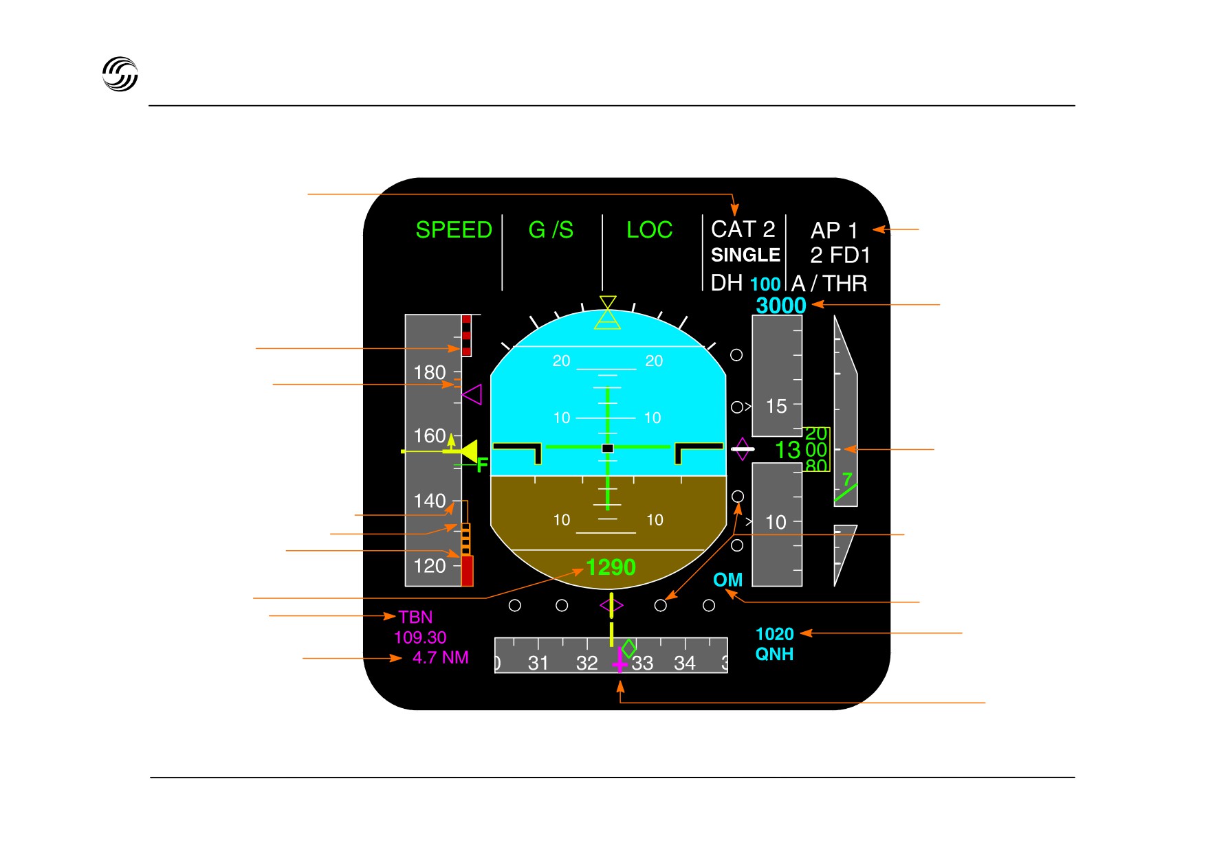
A319/A320/A321 EIS - PFD : approach configuration
Approach capability
and decision height
AP / FD and A / THR
engagement status
Selected altitude
VFE or actual
configuration
VFE of the next
configuration
Altitude indication
Minimum selectable speed
Alpha protection speed
G / S and LOC scales
Alpha max speed
and DEV indexes
Radio altitude
Outer marker “light”
ILS ident + freq
Altimeter baro
ILS - DME distance
setting display
ILS course
STL 945.7136/97
12.6
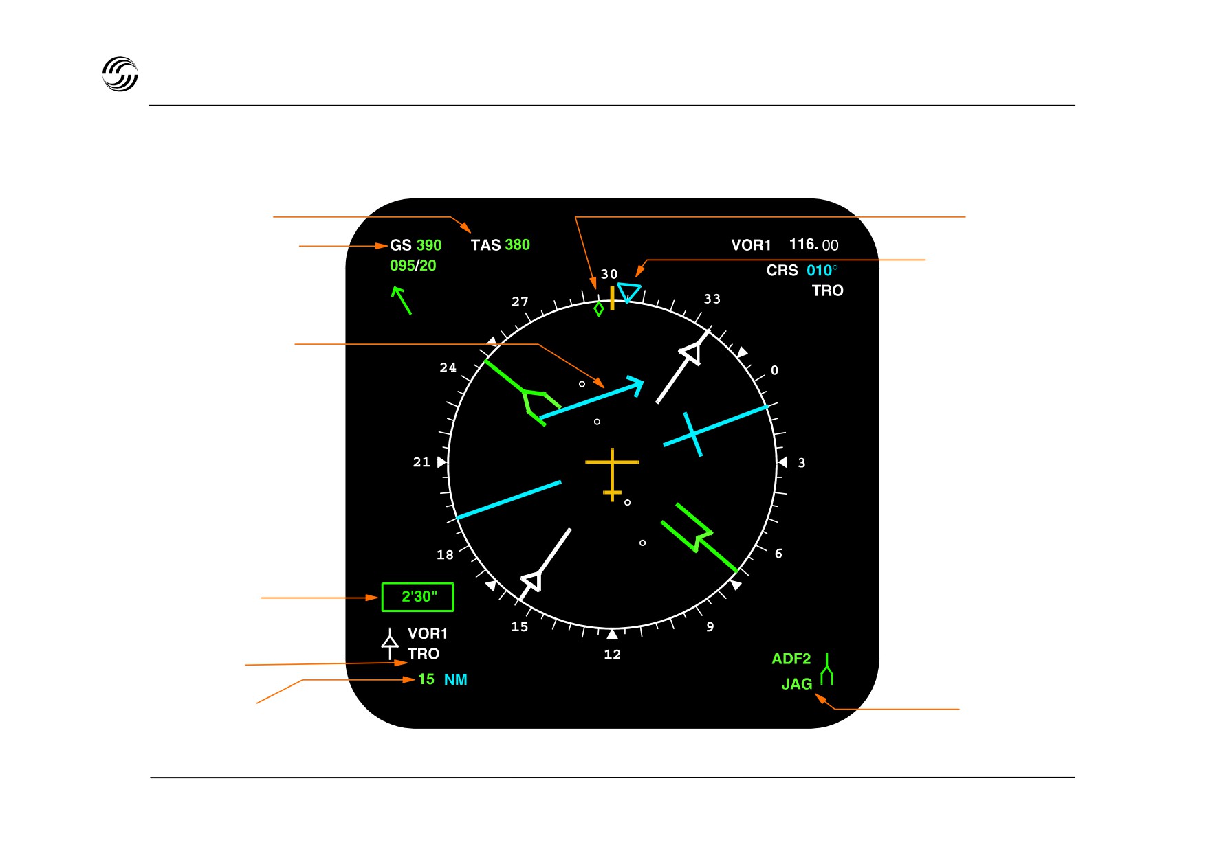
A319/A320/A321 EIS - ND : ROSE / VOR mode
True air speed
Actual track
Selected heading
Lateral deviation
bar
Elapsed time
VOR 1
identification
ADF 2
DME distance
Identification
STL 945.7136/97
12.7
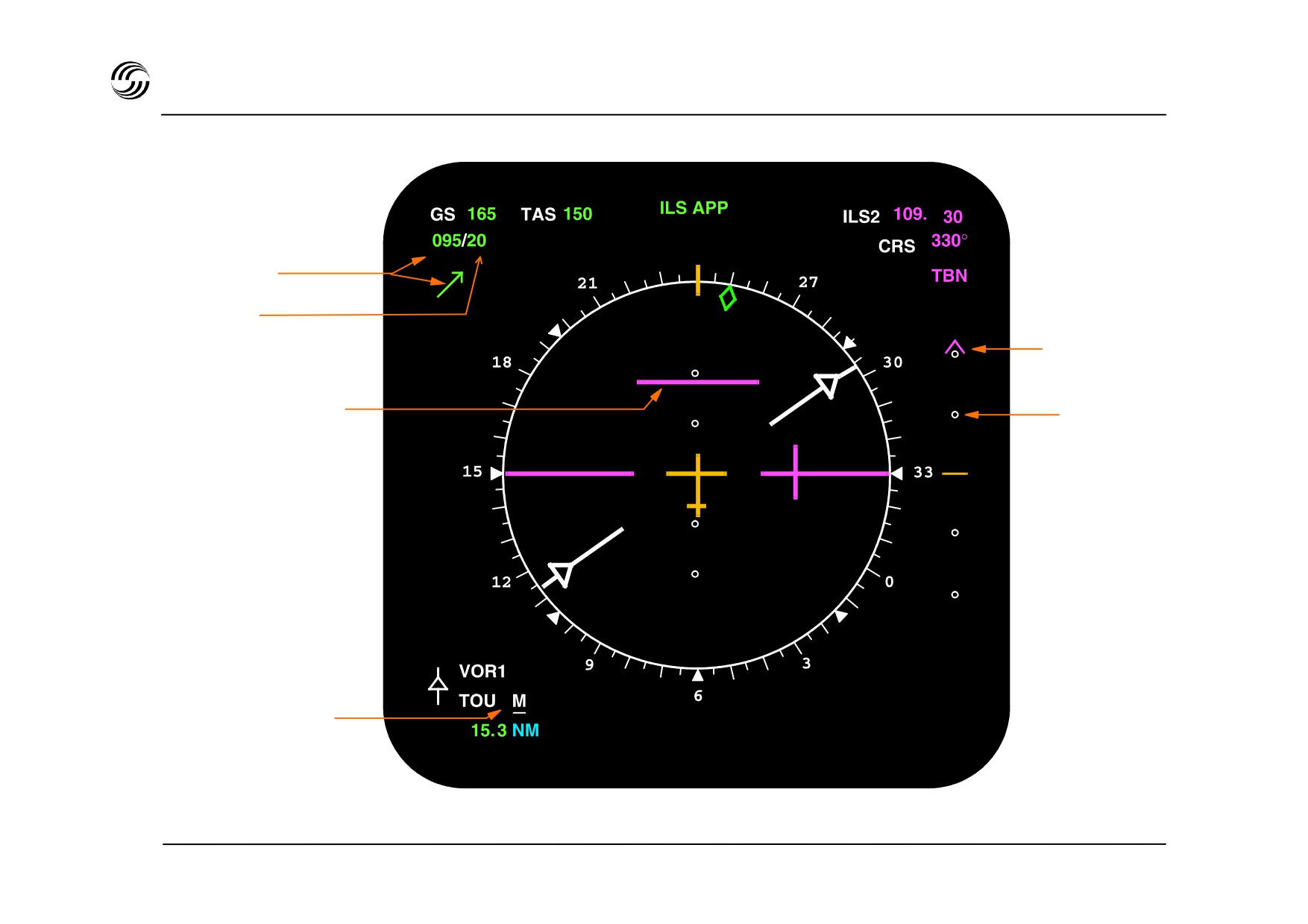
A319/A320/A321 EIS - ND : ROSE / ILS mode
Wind direction
Wind force
Glide deviation
Localizer deviation
Glide scale
bar
VOR 1
M=manuallytuned
STL 945.7136/97
12.8
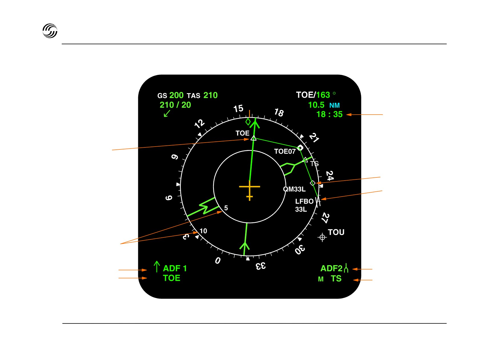
A319/A320/A321 EIS - ND : ROSE / NAV mode
ETA
ADF
Waypoint
Airport
Distance scale
ADF 1
ADF 2
Identification
M = manually tuned
STL 945.7136/97
12.9
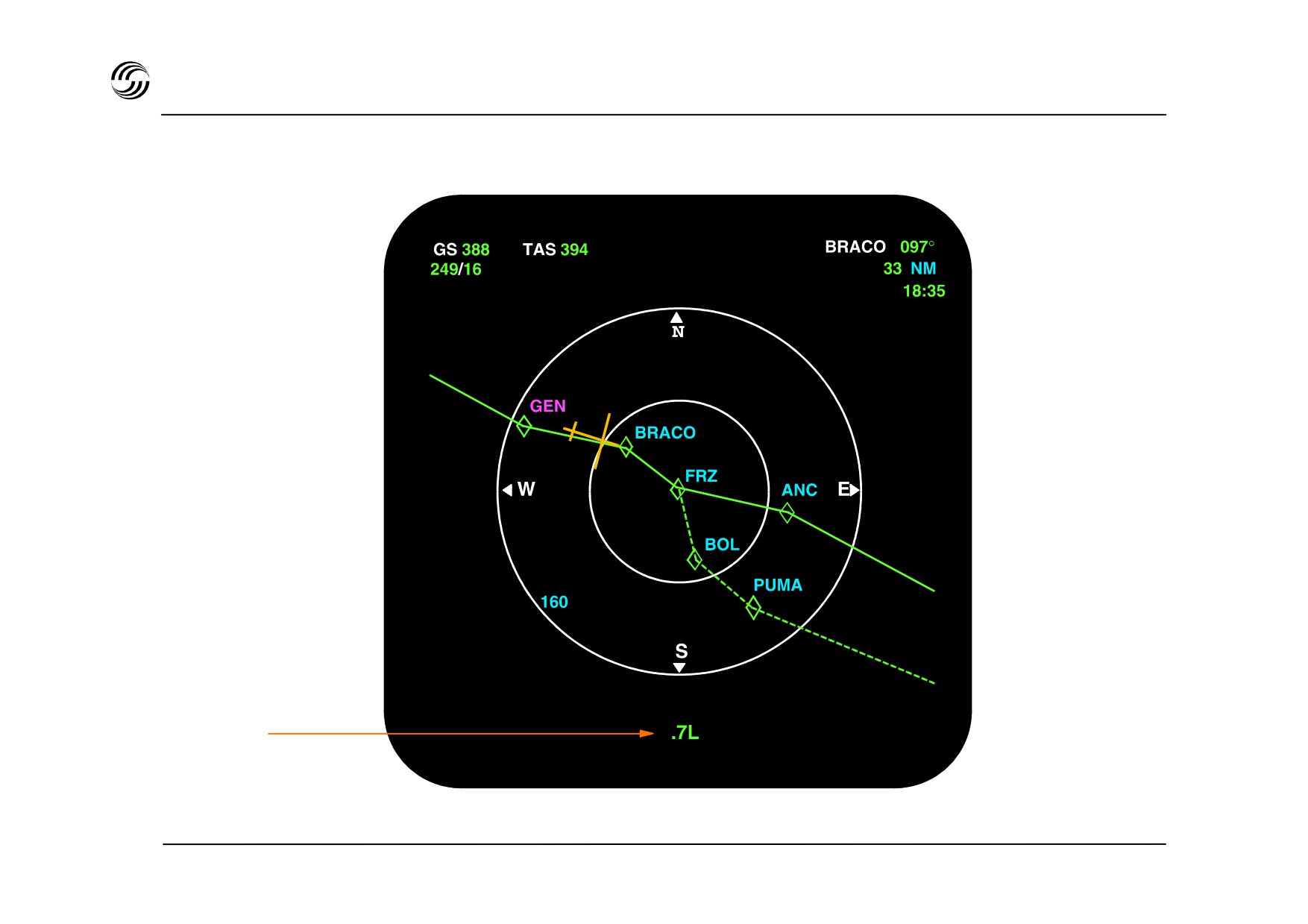
A319/A320/A321 EIS - ND : PLAN mode
Cross track
error
STL 945.7136/97
12.10
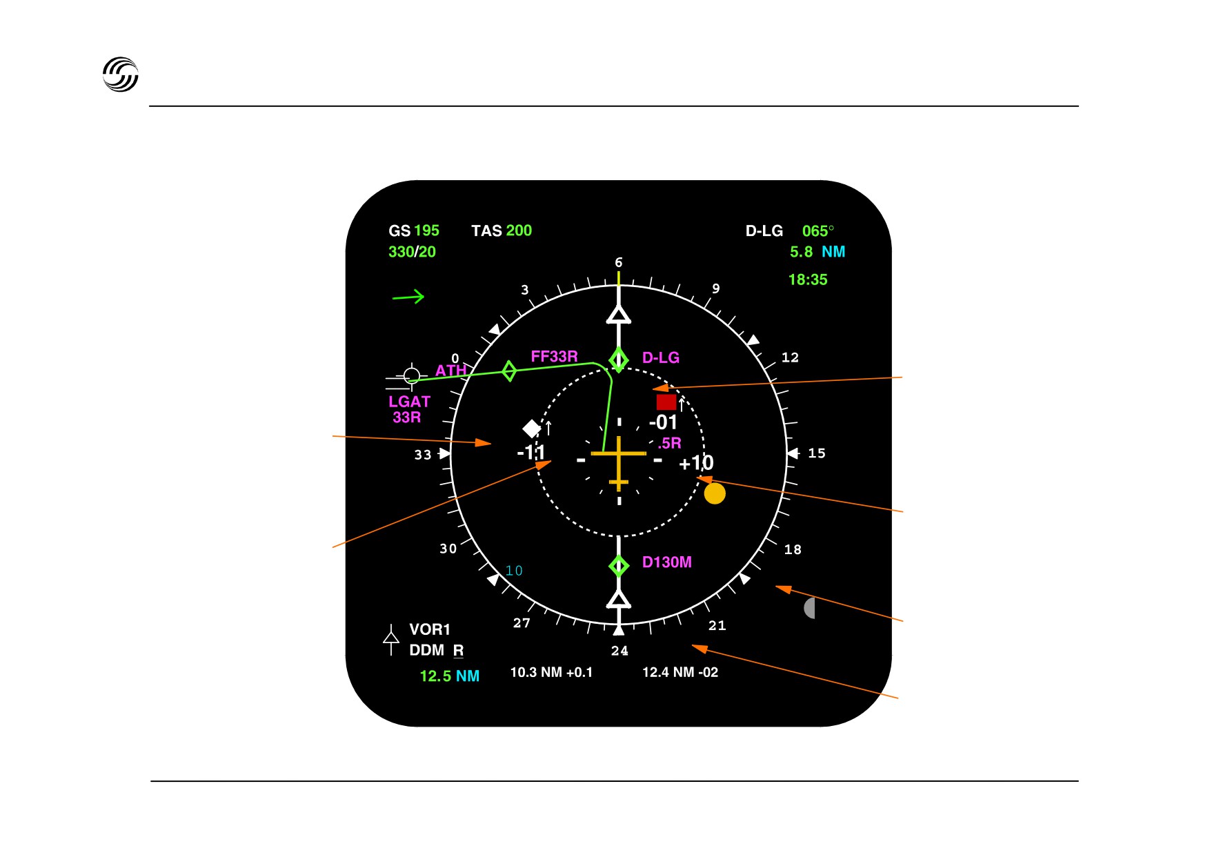
A319/A320/A321 EIS - ND : TCAS (optional)
Selected
Range : 20 nm
Resolution advisory :
RED
Proximate aircraft :
WHITE
Traffic advisory :
AMBER
2.5 nm range ring
Off scale intruder
No bearing intruders
STL 945.7136/97
12.11

A319/A320/A321 EIS - ECAM arrangement
z ECAM (EFIS) colour symbology
- Warnings
: RED
for configuration or failure
needing immediate action
- Cautions
: AMBER
for configuration or failure
needing awareness
- Indications : GREEN
for normal long term operations
WHITE
for titling and guiding remarks
BLUE
for actions to be carried out
MAGENTA
for particular messages, e.g.
inhibitions
z ECAM arrangement
Upper DU
- Engine primary indication
- Fuel quantity information
- Slats/flaps position
- Memo/configuration data or warning/caution messages
Lower DU
- Aircraft system synoptic diagram or status messages
STL 945.7136/97
12.12
A319/A320/A321 EIS - ECAM arrangement
ECAM sound Symbology
Warning signal
Condition
Duration
Continuous
Red warnings
Permanent
repetitive chime
Single chime
Amber caution
1 / 2 second
A/P disconnection by take-over pb
1.5 second
Cavalry change
A/P disconnection due to failure
Permanent
Click
Landing capability change
½ second (three pulses)
Cricket
Stall
Permanent
Intermittent buzzer
SELCAL call
Permanent
Continuous buzzer
Cabin call
Permanent
‘C’ chord
Altitude alert
1.5 second or Permanent
Auto call-out
Height announcement
Permanent
(synthetic voice)
below 400ft
Ground proximity
warning
GWPS warning
Permanent
(synthetic voice)
STL 945.7136/97
12.13
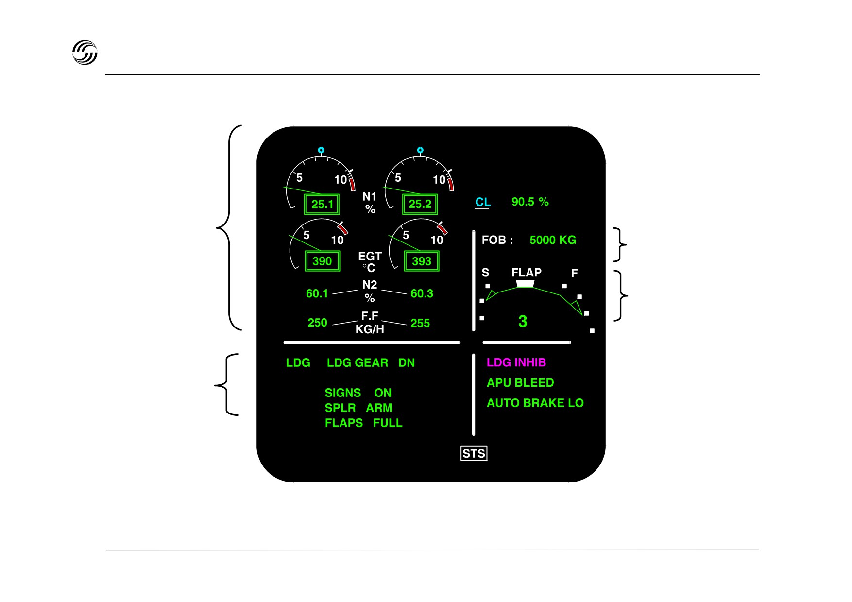
A319/A320/A321 EIS - ECAM upper display
Primary engine
indications
Fuel quantity indication
Flap / slats position
indication
MEMO :
landing
STL 945.7136/97
12.14

A319/A320/A321 EIS - ECAM upper display
z The ECAM upper DU can provide the following
memo items for systems which can be use
temporarily and for which no dedicated
annunciator lights are provided.
z Specific memos for take-off and landing are also
available when appropriate.
TO MEMO
LDG MEMO
IRS IN ALIGN X MIN
SPEED BRK
SWITCHING PNL
AUTO BRK…….MAX
LDG GEAR…….DN
IRS ALIGNED
PARK BRK
GPWS FLAP 3
SIGNS …………ON
SIGNS …………ON
SEA BELTS
HYD PTU
ACARS STBY
SPLRS …………ARM
SPLRS …………ARM
NO SMOKING
RAT OUT
MAN LDG ELEV
FLAPS …………TO
FLAPS …………FULL
REFUEL G
EMER GEN
CRT TK FEEDG
TO CONFIG ….. TEST
or
CONFIG 3
OUTR CELL FUELXFRD
RAM AIR ON
FUEL X FEED
CABIN ………… READY
STROBE LT OFF
ACARS CALL
T.O. INHIB
N. WHEEL STEERG DISC
ACARS MSG.
LDG INHIB
IGNITION
ENG A.ICE
LAND ASAP
GND SPLRS ARMED
WING A.ICE
OFF
GPWS FLAP MODE OFF
APU AVAIL
LO
APU BLEED
AUTO BRK
MED
LDG LT
MAX
BRK FAN
AUDIO 3 X FRD
STL 945.7136/97
12.15
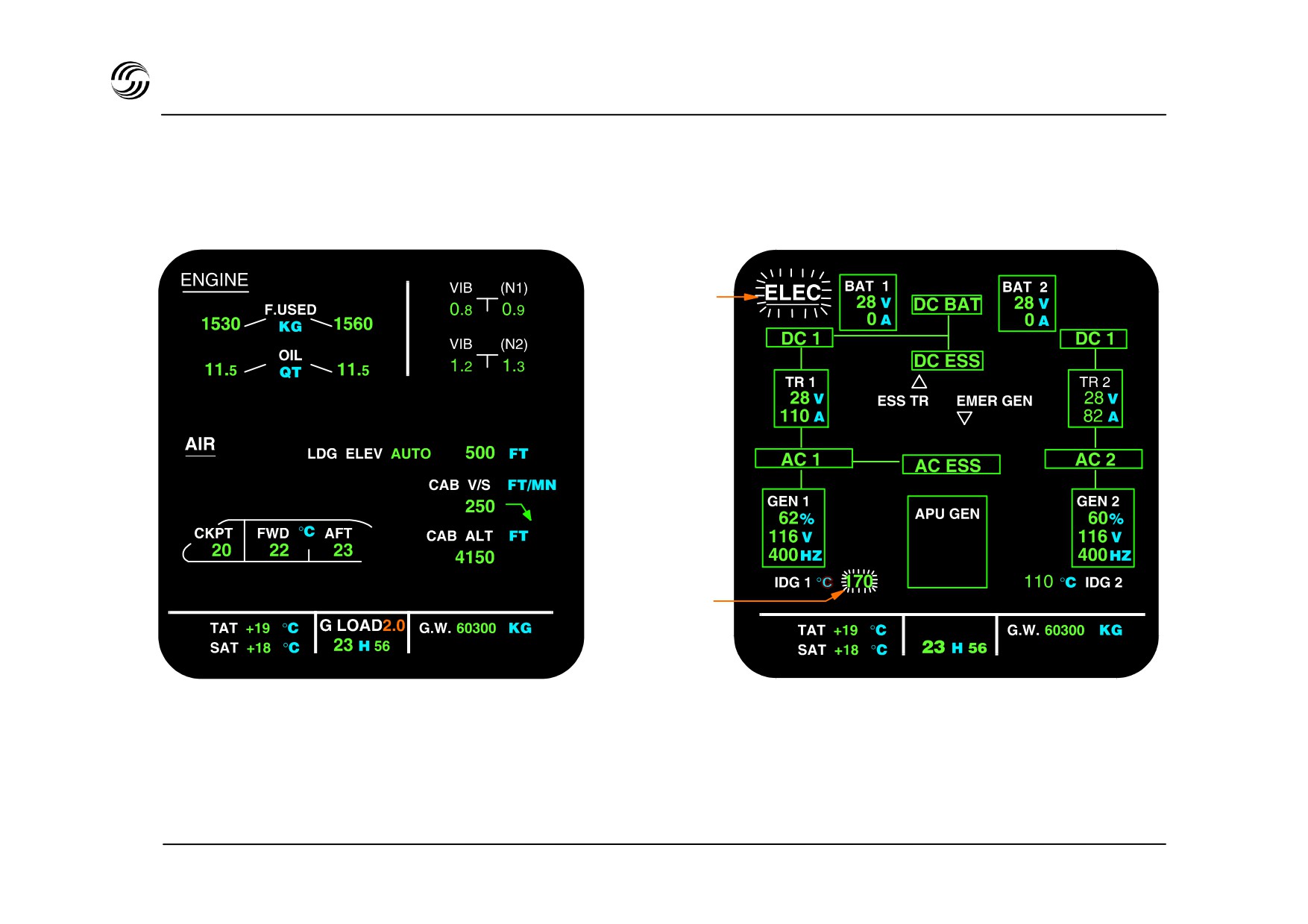
A319/A320/A321 EIS - ECAM lower DU
Cruise page
Electrical system page with advisory
Title of the
system page
pulsing
Value pulsing
STL 945.7136/97
12.16

A319/A320/A321 EIS - ECAM lower DU
z The ECAM lower DU presents either (one of twelve)
system pages or status pages.
z Selection of System page is :
- either manual from the ECAM control panel,
- or automatic
in association with a warning/caution message,
•
with an advisory pulse message when a
•
parameter drifts out of range
according to flight phase.
•
z
12 available pages :
Air bleed,
Air conditioning,
Cabin pressurization,
Electrical power supply - AC / DC,
Flight controls,
Fuel,
Hydraulics,
APU,
Engine monitoring,
Doors / oxygen,
Braking (wheel, ground spoiler),
Cruise.
STL 945.7136/97
12.17
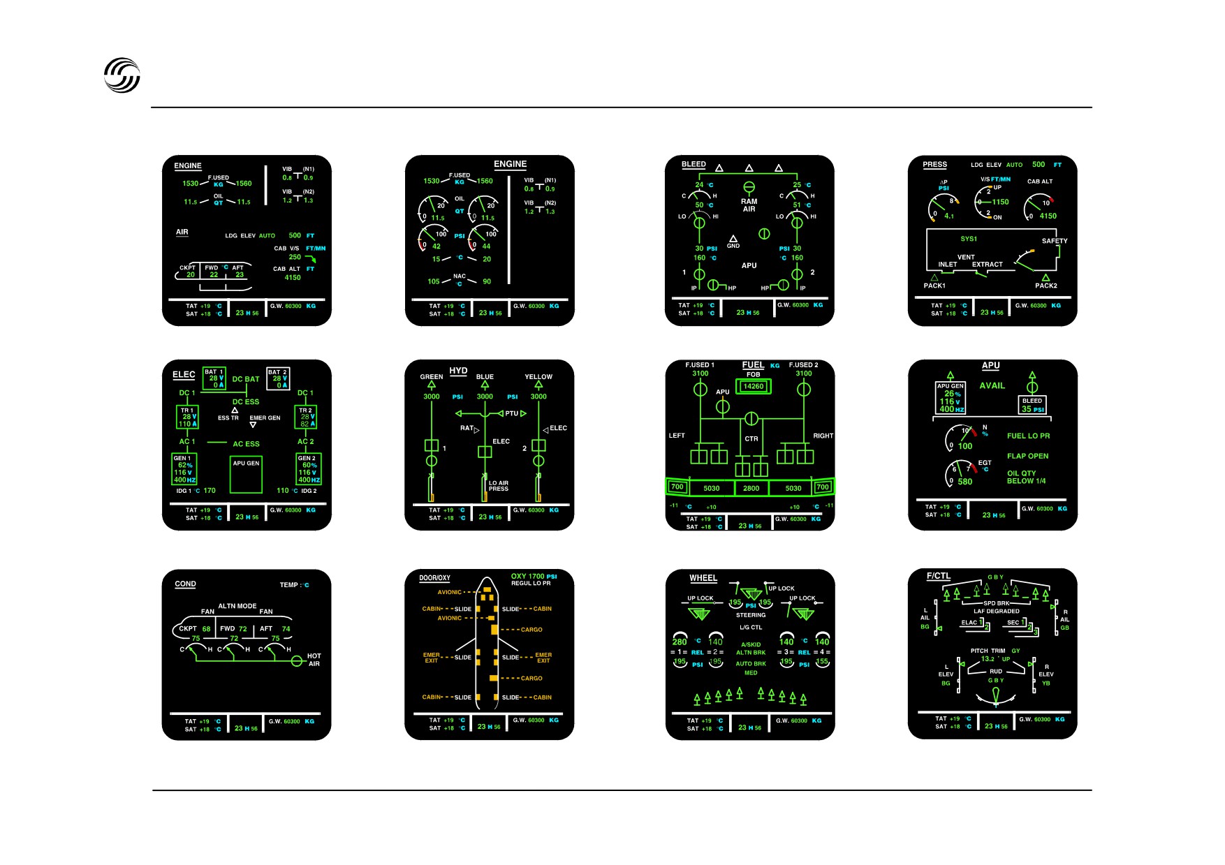
A319/A320/A321 EIS - ECAM system pages
Cruise page
Engine page
Air bleed page
Cabin pressurization page
Electric page
Hydraulic page
Fuel page
APU page
Air conditioning page
Doors/oxygen page
Wheel page
Flight controls page
STL 945.7136/97
12.18
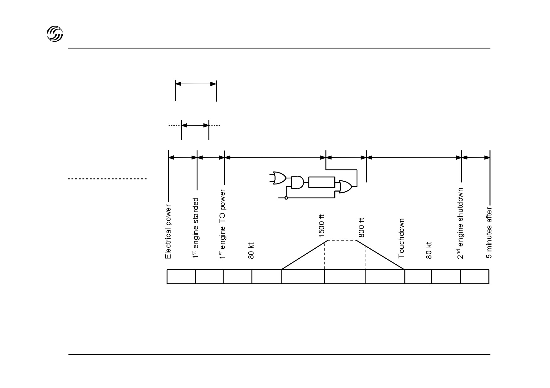
A319/A320/A321 EIS - ECAM lower display - auto flight phase
Engine**
start
System
APU**
pages
Door Wheel
Engine
Cruise
Wheel
Door
* FLT
S/F extended
CTL
L/G
To PWR
1 MIN
extended
Phase 6
and altitude < 10000ft
Flight
phases
(FWC)
1
2
3
4
5
6
7
8
9
10
* FLT CTL page replaces wheel page for 20 seconds when either sidestick is moved or when rudder deflection is
above 22°.
** APU page or EBG START page automatically displayed during start sequence.
STL 945.7136/97
12.19

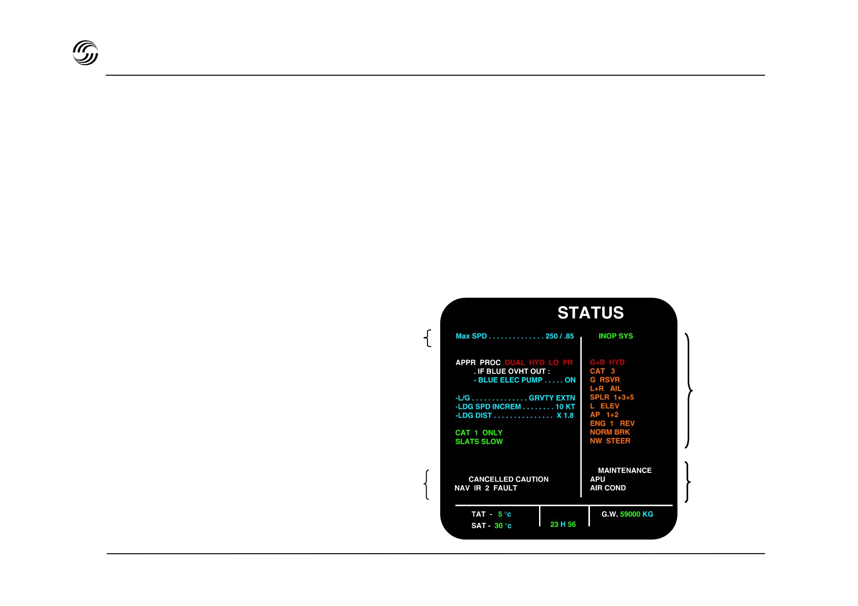
A319/A320/A321 EIS - ECAM lower display
Status page
The operational summary of the aircraft status after a
failure is displayed on the lower ECAM DU and includes :
(a)
Postponable procedures not displayed on first page
(blue)
(b)
Limitations (speed, flight level…) (blue)
(c)
Informations (green)
(d)
Cancelled cautions or warnings (white)
(e)
Inoperative systems (amber)
(f)
Maintenance status (white)
b
a
e
c
f
d
STL 945.7136/97
12.21
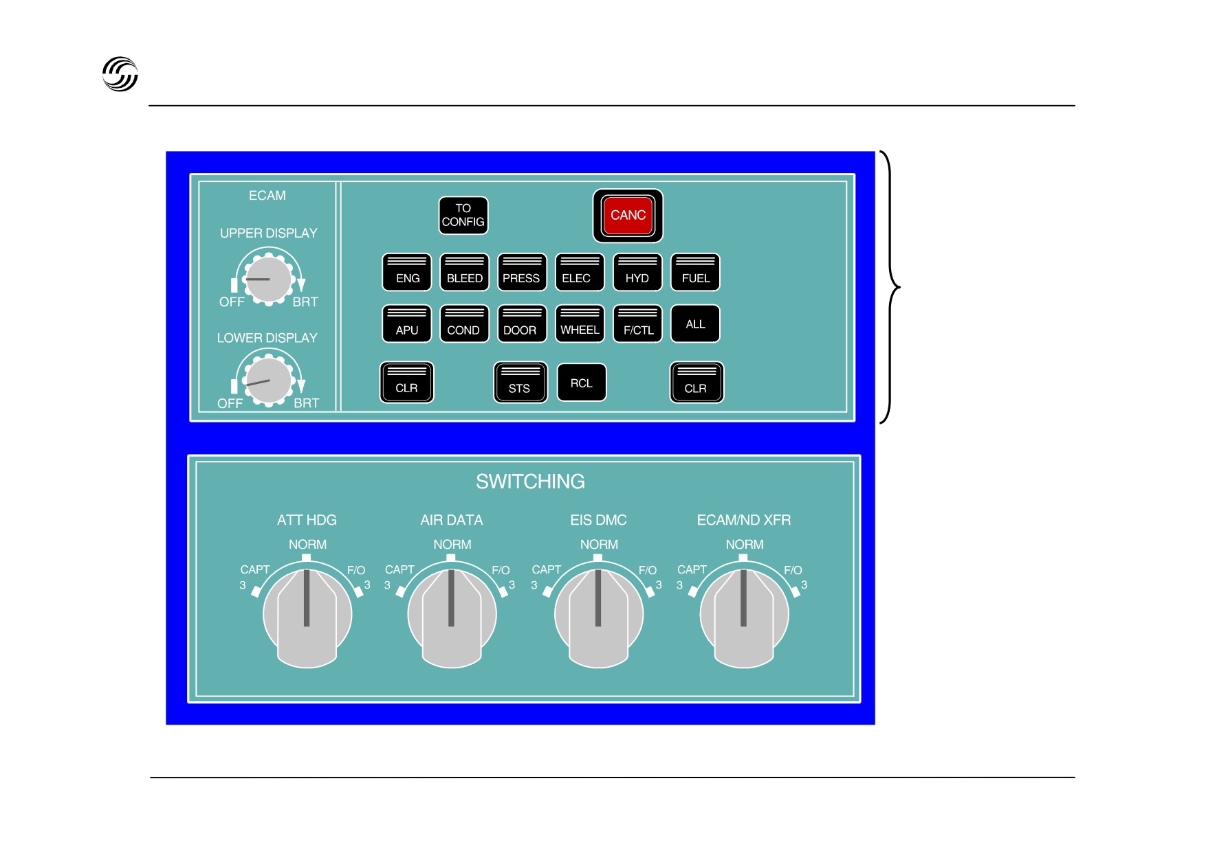
A319/A320/A321 EIS - ECAM control / switching panels
System page
control
STL 945.7136/97
12.22
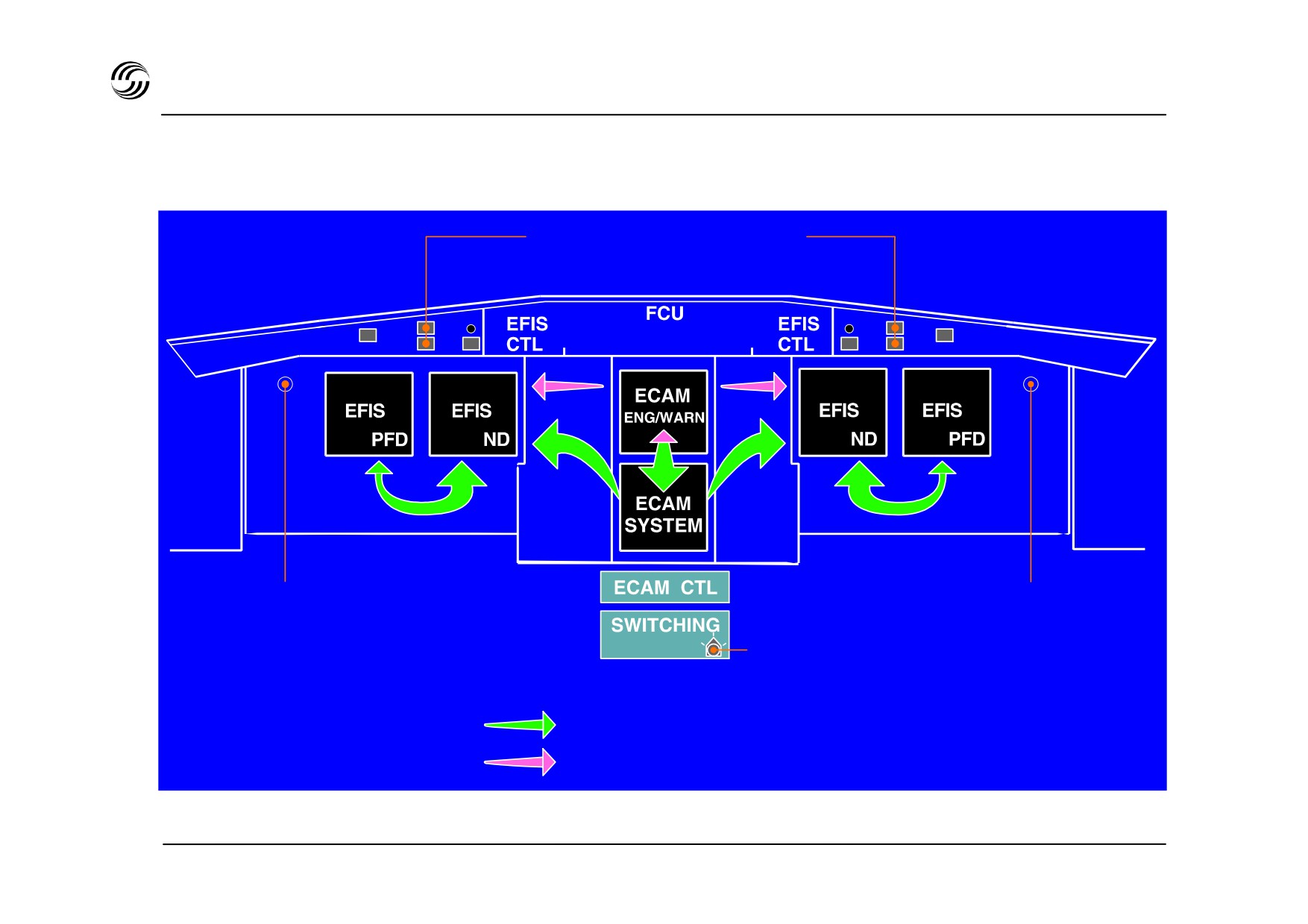
A319/A320/A321 EIS - Dus reconfiguration
Master warning (red)
Maser caution (amber)
PFD/ND
PFD/ND
Transfer
Transfer
ECAM/ND
Transfer
Reconfiguration capability :
Single failure
Multiple failure
STL 945.7136/97
12.23


A319/A320/A321 - EIS
Independent failure
presentation sequence
Example : electrical generator fault
STL 945.7136/97
12.25

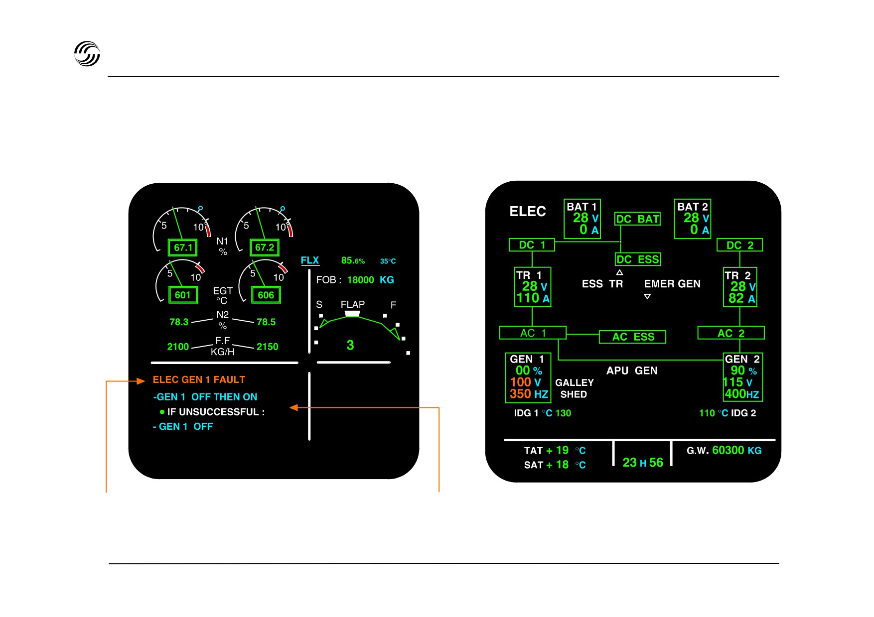
A320 EIS - independent failure : initiation
The following displays appear, provided no flight phase inhibition is active.
ECAM lower display : ELEC page
ECAM upper display
Failure identification
Corrective actions
The corresponding system page appears automatically
STL 945.7136/97
12.27
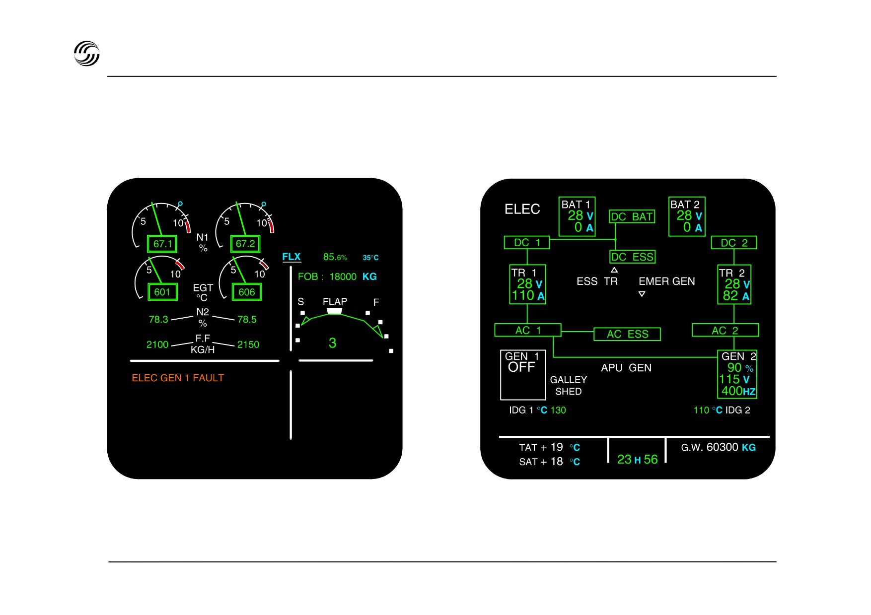
A319/A320/A321 EIS - independent failure : after corrective action
ECAM upper display
ECAM lower display : ELEC page
Actions lines automatically cleared when
ELEC page changes according to the corrective action
corresponding actions performed
STL 945.7136/97
12.28
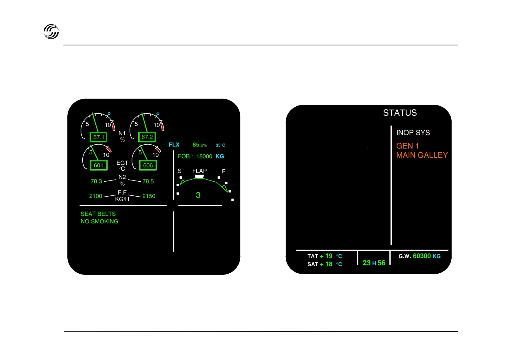
A319/A320/A321 EIS - independent failure : after “clear”action
ECAM upper display
ECAM lower display
APU GEN UP TO FL 350
- Warning message is cleared
- Status page appears automatically
- Memo comes back
- When “clear” button is pressed again
flight phase system page comes back
STL 945.7136/97
12.29


A319/A320/A321 - EIS
Primary / secondary
failure presentation sequence
Example : Blue hydraulic reservoir low air pressure
corrective action leading to primary
failure
: Blue hydraulic system low
pressure
STL 945.7136/97
12.31

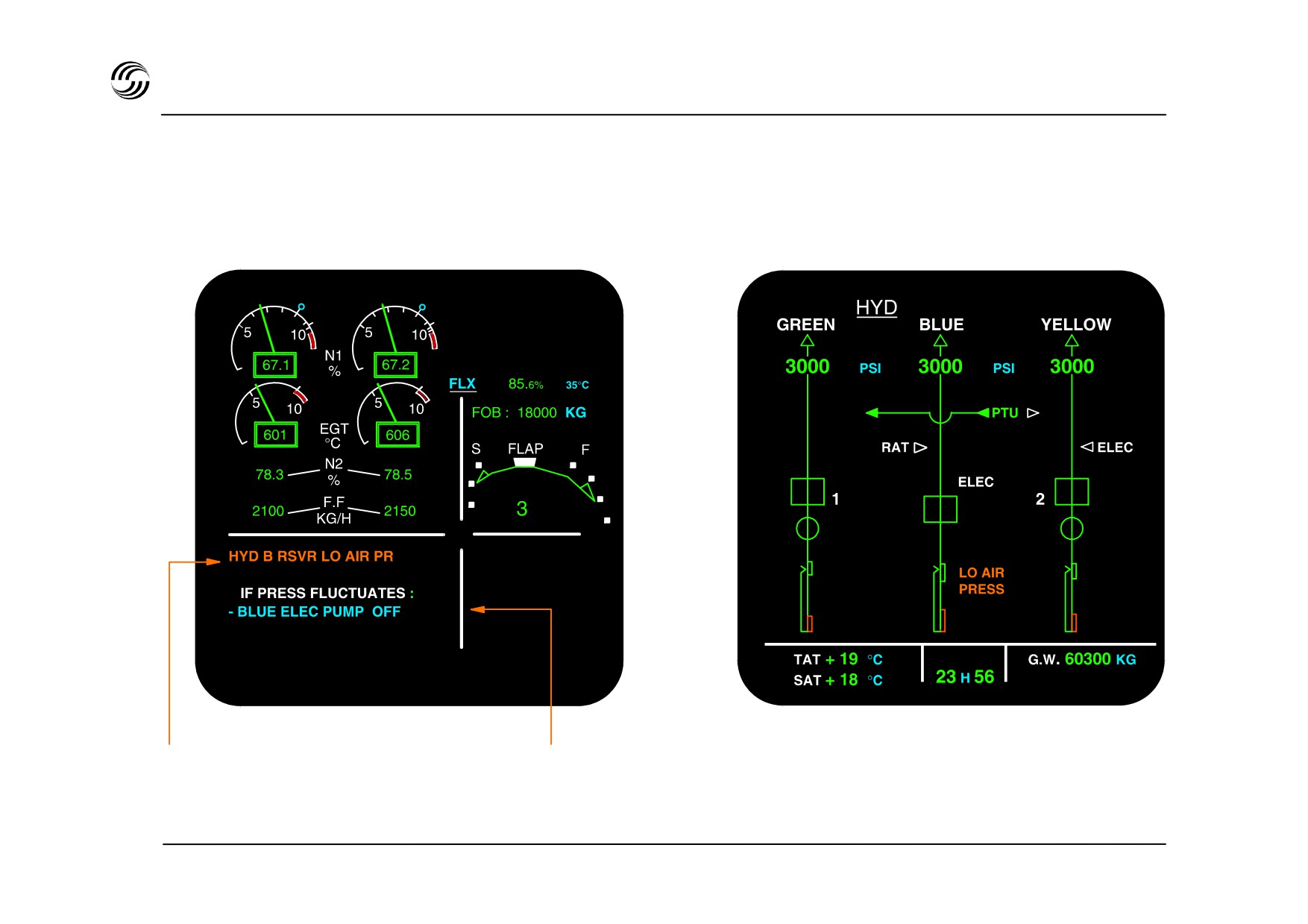
A319/A320/A321 - EIS - primary / secondary failure : initiation
1st step : independent failure detection
Upper display
Lower display : HYD page
Failure identification
Corrective action
The corresponding system page appears automatically
STL 945.7136/97
12.33
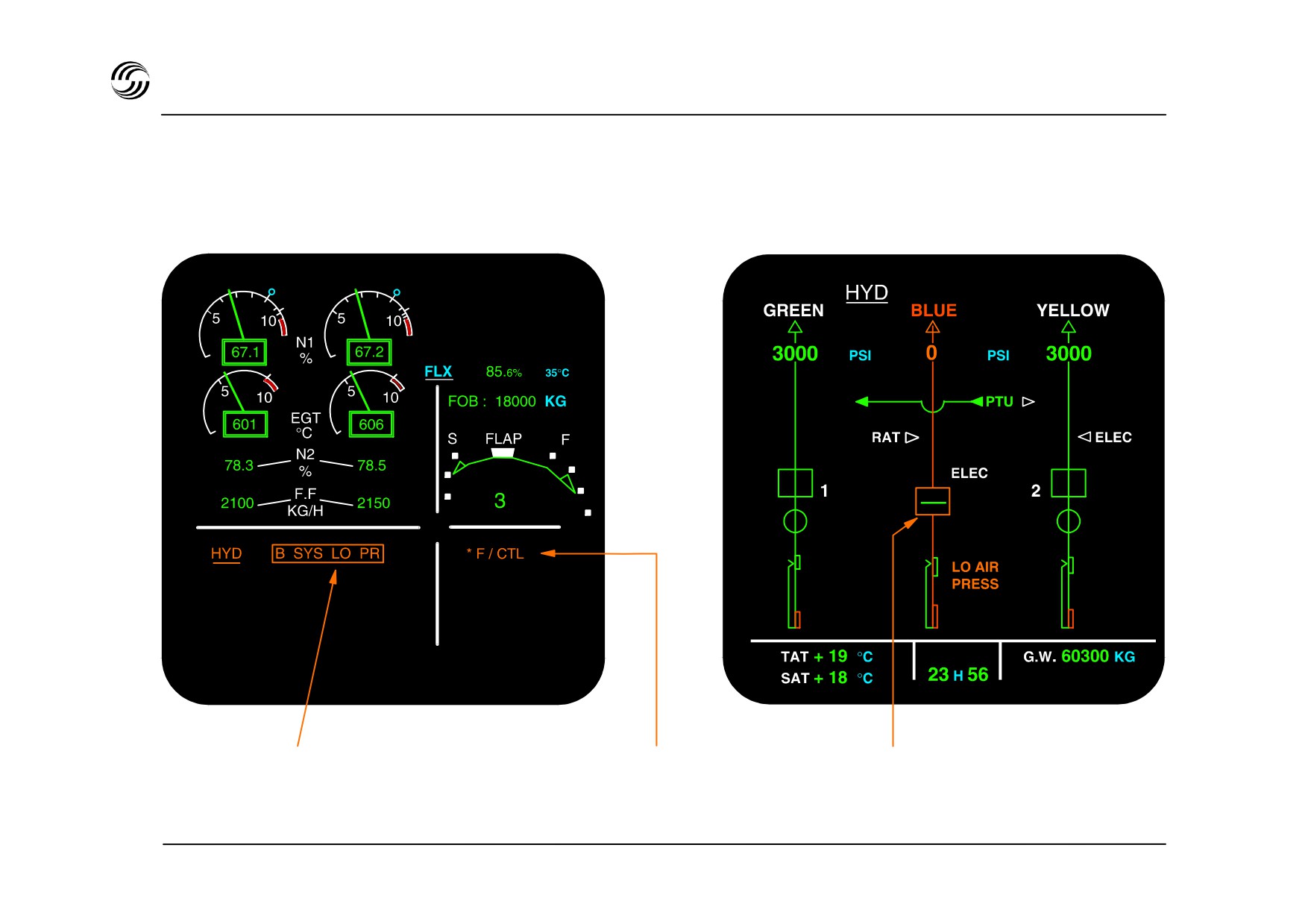
A320 - primary / secondary failure : after corrective action
2st step : after performing the corrective action
Upper display
Lower display : HYD page
Display of resulting
Resulting secondary
The corresponding system page is
primary failure
failure is displayed
automatically updated
STL 945.7136/97
12.34
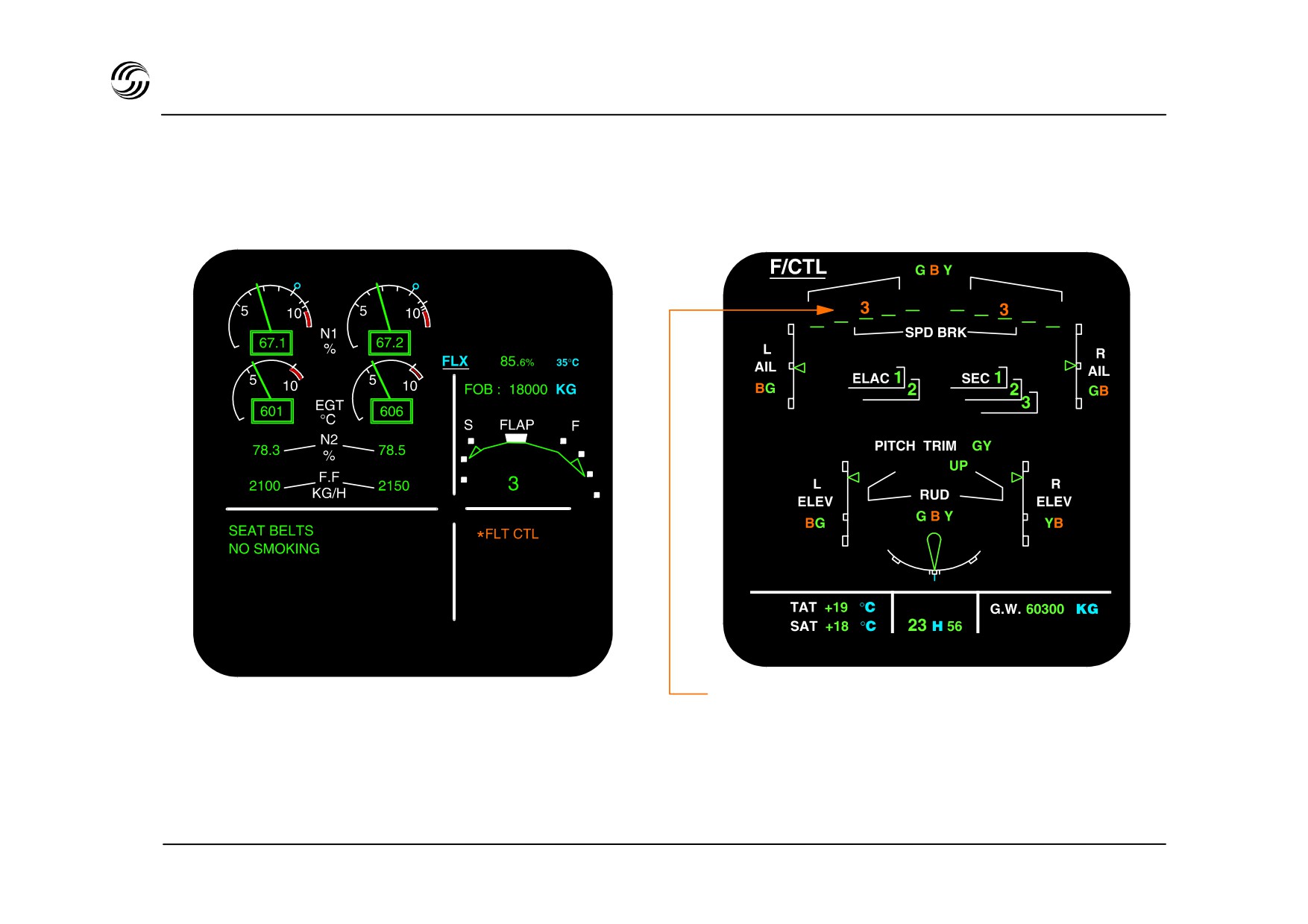
A319/A320/A321 EIS - primary / secondary failure : after “clear” action 1
3rd step : first “CLEAR”
Upper display
Lower display : F / CTL page
Resulting secondary failure (spoiler fault and all actuator
blue press indications amber) related to primary failure
(Blue system low press)
- Warning message is cleared
- Memo comes back
The system page corresponding to
the secondary failure is
automatically displayed
STL 945.7136/97
12.35
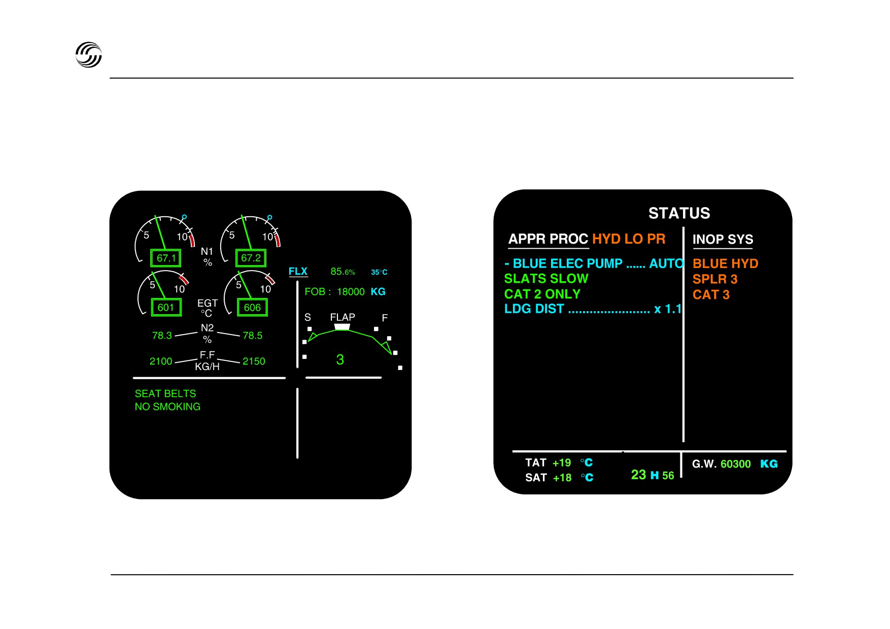
A319/A320/A321 EIS - primary / secondary failure : after “clear” actions 2
4th step : second “CLEAR”
Upper display
Lower display : status page
- Status page appears automatically after
second “clear”
STL 945.7136/97
12.36
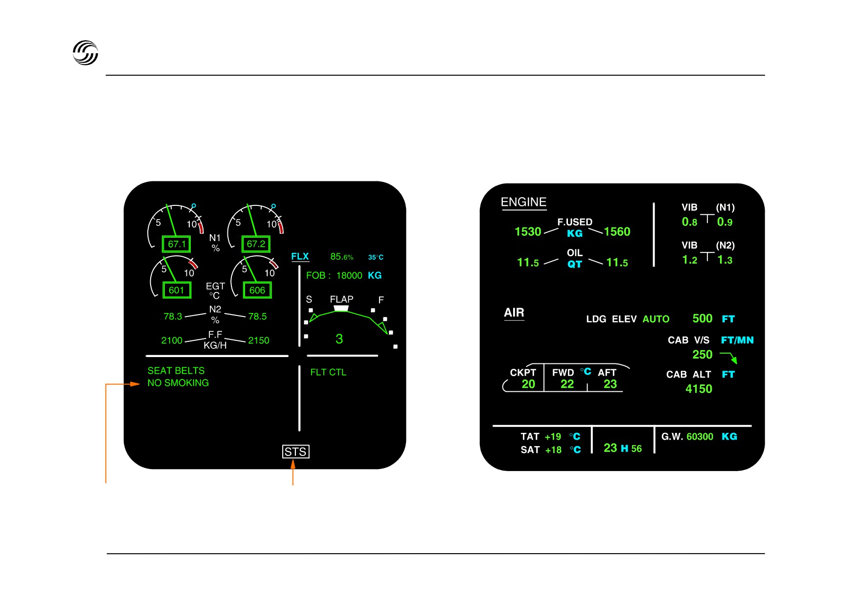
A319/A320/A321 EIS - primary / secondary failure : after “clear” actions 3
5th step : third “CLEAR”
Upper display
Lower display : cruise page
Display of entire memo
Status reminder
- When “clear” button is pressed for the third
consecutive time, flight phase system
page comes back
STL 945.7136/97
12.37


13. Radio managementand
communication
STL 945.7136/97
13.1
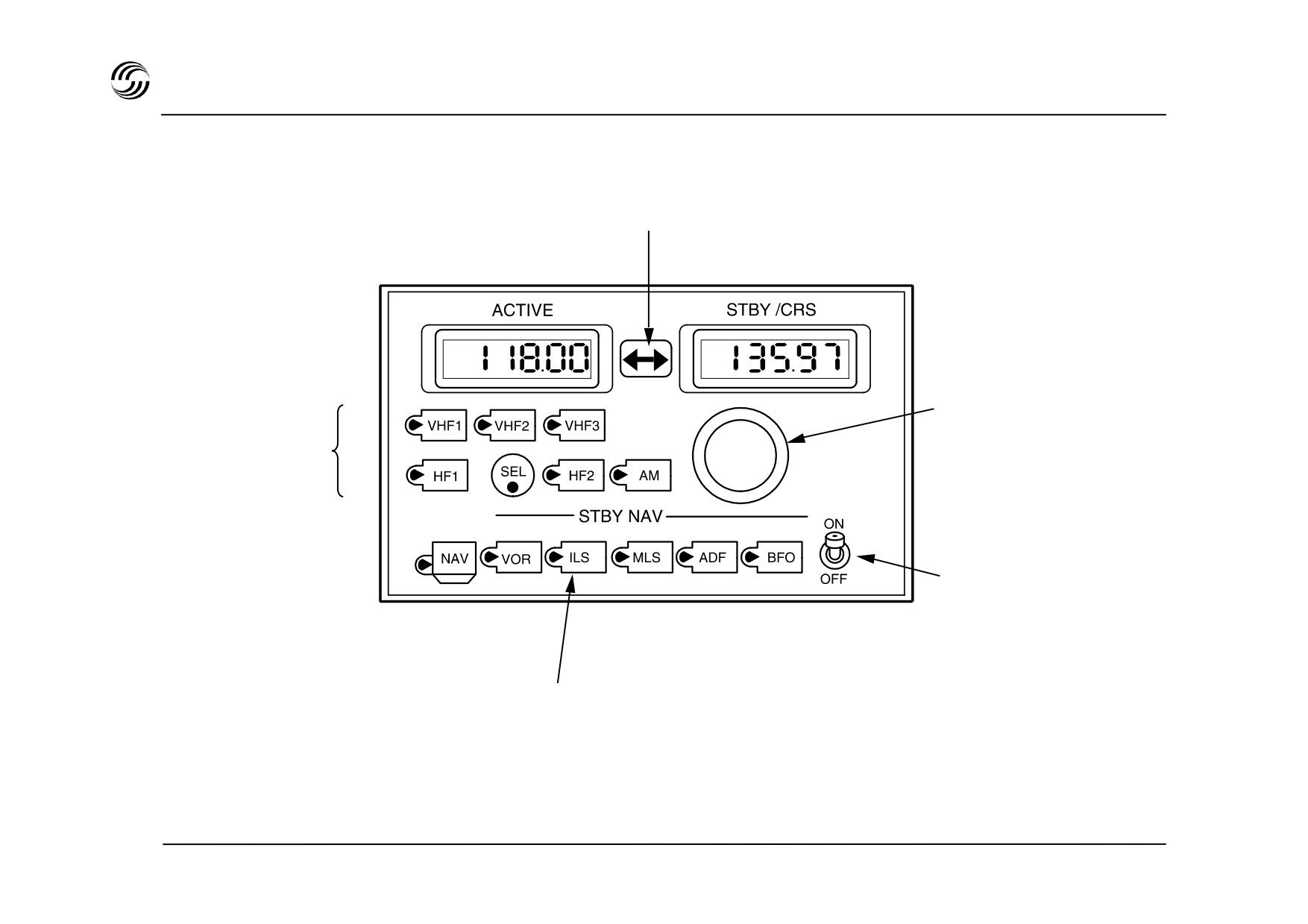
A319/A320/A321 radio management concept
Radio Management Panel (RMP)
Transfer function
Frequency selection
(two concentric
Radio COMM
rotation knobs)
selection keys
Isolation switch
Radio NAV back-up section
(when both MCDUs or FMGCs failed)
STL 945.7136/97
13.2

A319/A320/A321 radio management concept
z Radio Management Panel (RMP) system provides :
- crew control of all radio communication systems
- back-up of the two FMGCs for controlling all radio
navigation systems
z Basic installation includes :
- two RMPs on pedestal
- full provision for installation of a third RMP on
overhead panel
z The ATC transponder is tuned by a separate
conventional control panel.
STL 945.7136/97
13.3
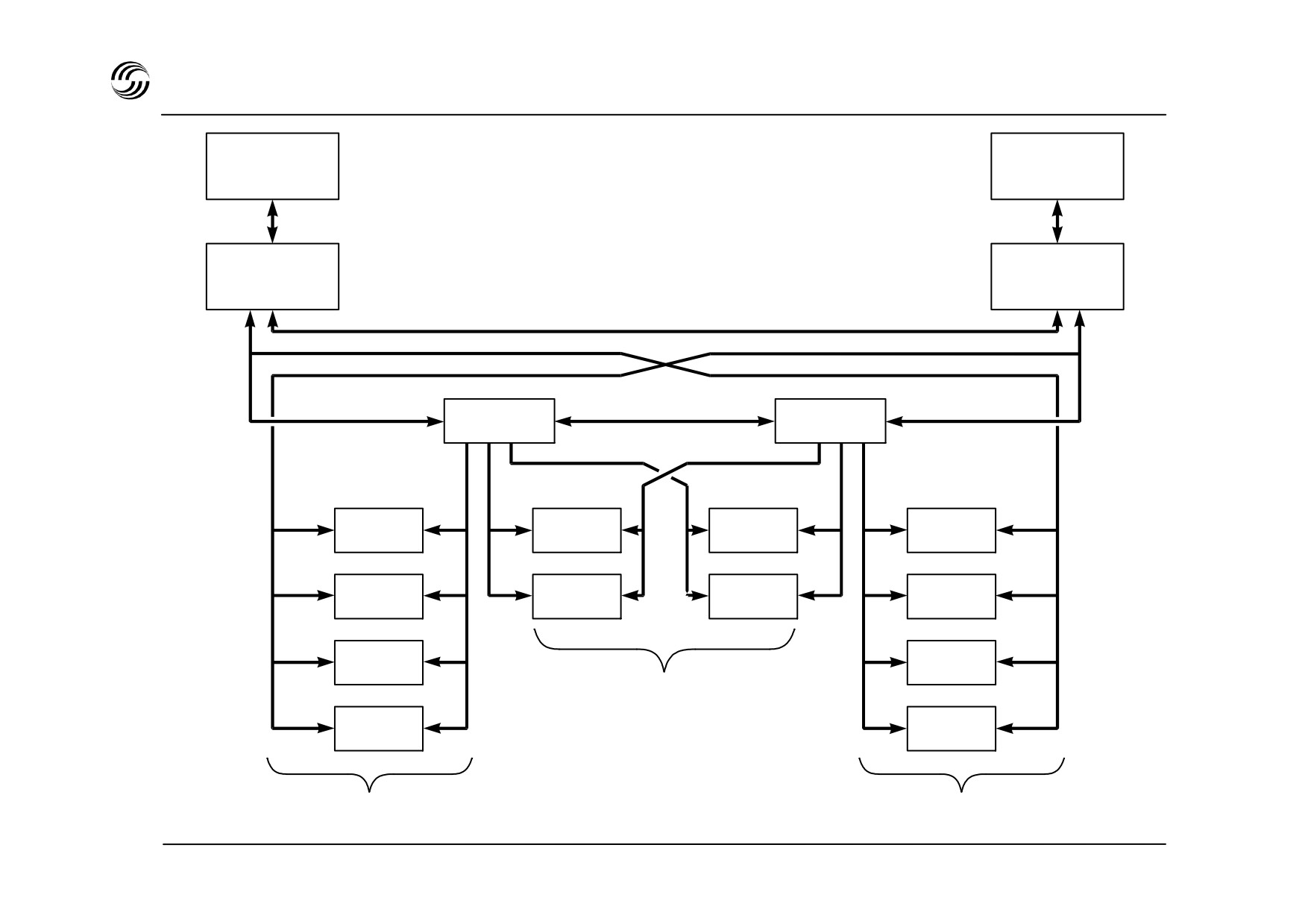
A319/A320/A321 RMP architecture
MCDU 2
MCDU 1
FMGC 1
FMGC 2
RMP 1
RMP 2
VOR 1
VHF 1
VHF 2
VOR 2
DME 1
HF 1
HF 2
DME 2
ILS 1
ILS 2
COMM.
ADF 1
ADF 2
NAV
NAV
STL 945.7136/97
13.4

A319/A320/A321 radio management concept architecture
Communication tuning
Any radio communication system can be tuned from any of
two RMPs. In case of failure any RMP can take over from the
other one.
Navigation tuning
Three different operating modes exist.
z Automatic
: VOR/DME, ILS and ADF are automatically
tuning controlled by the FMGS.
z Manual tuning : for selection if a specific frequency
through the FMGS CDU without affecting
the automatic function of the FMGS.
z Back-up tuning : when both FMGCs are inoperative or
when an emergency electrical source is in
operation, any NAV receiver may be tuned
by the crew from any RMP ; each RMP
controls on side receivers.
When one of both FMGCs is inoperative, the remaining one
controls all receivers.
STL 945.7136/97
13.5
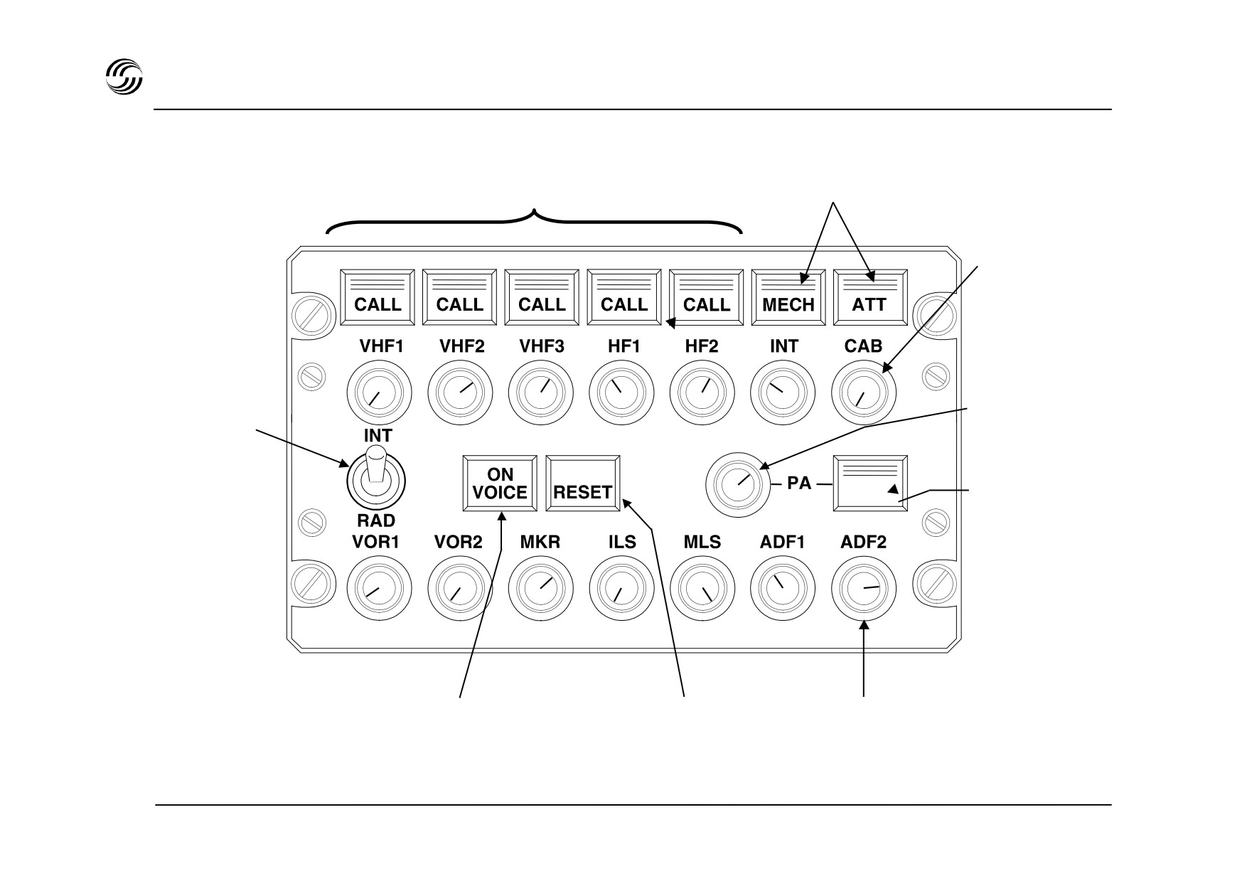
A319/A320/A321 COMM - audio control panel
Transmission keys
Transmission keys
and SELCAL lights
and CALL lights
Audio listening
and volume control
Public address
Interphone/Off
audio listening and
/Radio switch
volume control
PA key for boomset
oxygen mask or
hand microphone
operation
Voice/ident
SELCAL and CALL
Radio nav audio listening
filter key
reset key
and volume control
STL 945.7136/97
13.6

A319/A320/A321 COMM - audio control panel
The audio integrating system provides the management of
all audio signals produced by and feeding the radio-
communications, radio navigation and interphone systems :
z Basic installation includes :
- three Audio Control Panel (ACP) - two on pedestal,
one on overhead panel
- one Audio Management Unit (AMU) in avionics bay
- one SELCAL code selector in avionics bay.
z Provision exists for supplementary ACP’s
z All selections and volume adjustments carried out by
crew through ACPs
z All ACPs are fitted for maximum capacity (three VHF,
two HF, public address, calls, two VOR, two ADF, ILS
and provision for MLS).
z Each ACP and associated AMU electronic card are fully
independent and microprocessor controlled.
STL 945.7136/97
13.7


14. Maintenancecentralized
fault displaysystem
STL 945.7136/97
14.1


A319/A320/A321 Centralized Fault Display System (CFDS)
General
Line maintenance of the electronic systems is based on the
used of a Centralized Fault Display System (CFDS).
The purpose of the CFDS is to give maintenance
technicians a central maintenance aid to intervene at
system or subsystem level from multipurpose CDUs located
in the cockpit :
- to read the maintenance information
- to initiate various tests.
Two levels of maintenance should be possible using the
CFDS :
- maintenance at an out-station (LRU change)
- maintenance in the hangar or at the main base
(troubleshooting).
STL 945.7136/97
14.3
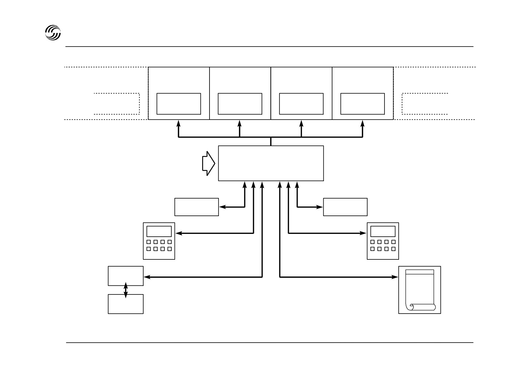
A319/A320/A321 CFDS - architecture
Aircraft systems
Aircraft
system
BITE
General parameters :
- date / time
CFDIU
- flight No.
- aircraft identification
- flight phases
FMGS
AIDS
1 and 2
MCDU 1
MCDU 2
ACARS
VHF 3
Printer
STL 945.7136/97
14.4

A319/A320/A321 CFDS - architecture
Advantages of the CFDS
z Optional equipment
A revised maintenance concept provides a :
- A multi-use printer
- A quick access recorder (QAR)
- reduction of the duration of operations
- An AIDS
- reduction of the maintenance crew training time
- simplification of technical documentation
- standardization of the equipment
- simplification of the computers which no longer
display any BITE ;
Integration of the CFDS
Integrated in the Maintenance and Recording Data
System (MRDS) comprising :
z Basic equipment
- A Centralized Fault Display Interface Unit (CFDIU)
- A digital Flight Data Recorder
(DFDR) and its
interface unit
- Two multipurpose CDUs (MCDUS) located on the
pedestal.
Note : The MCDUS can be used for : FMS, MRDS
options (ACARS, AIDS).
STL 945.7136/97
14.5
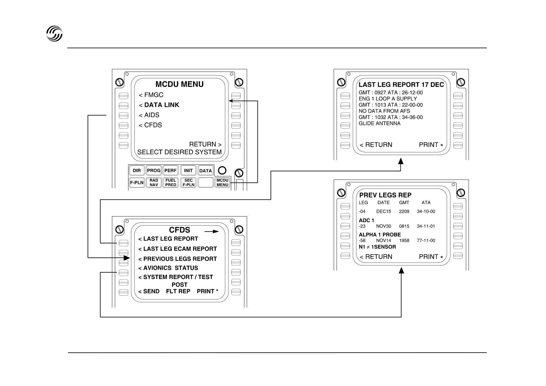
A319/A320/A321 CFDS - example of use - 1
STL 945.7136/97
14.6
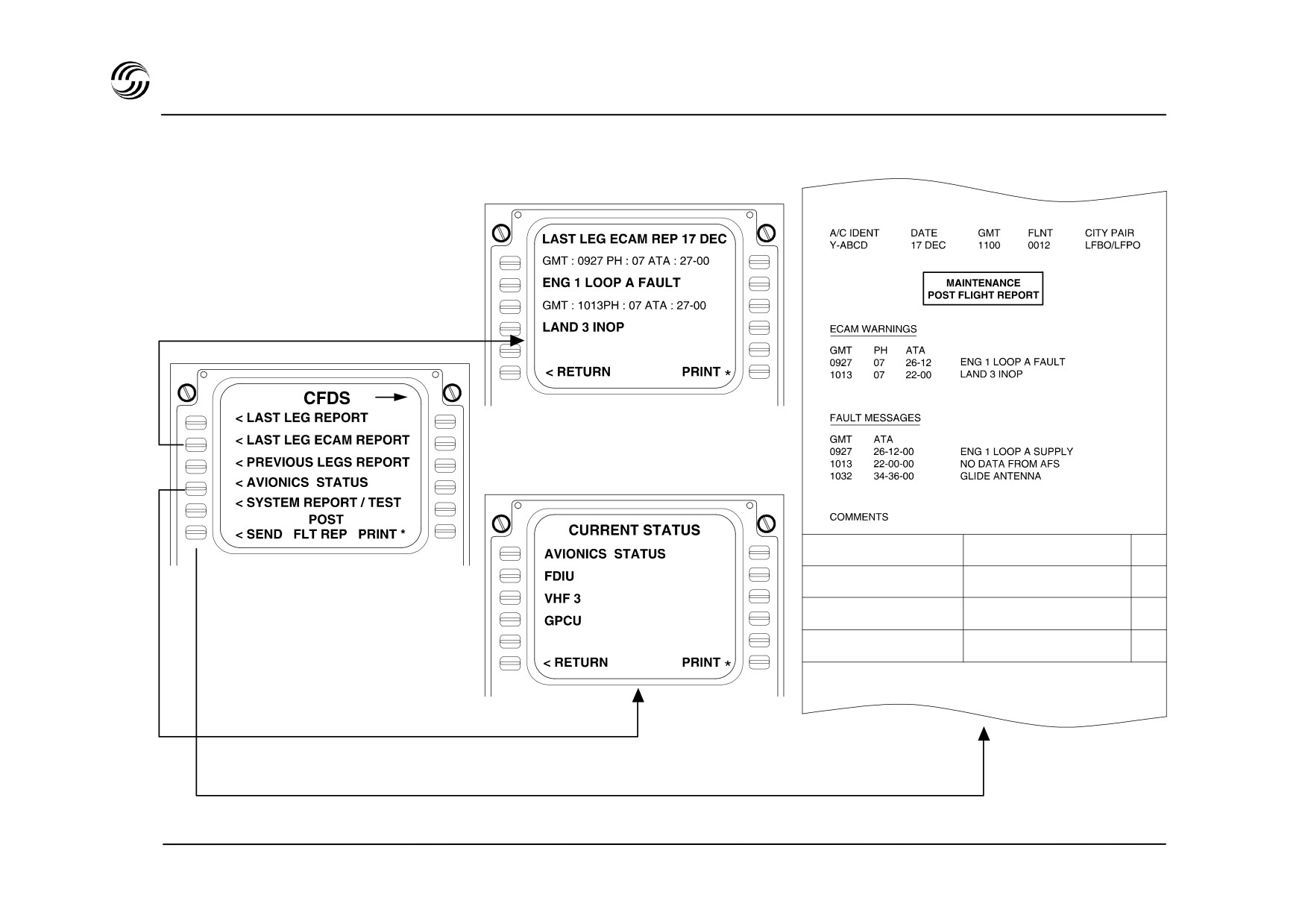
A319/A320/A321 CFDS - example of use - 2
STL 945.7136/97
14.7

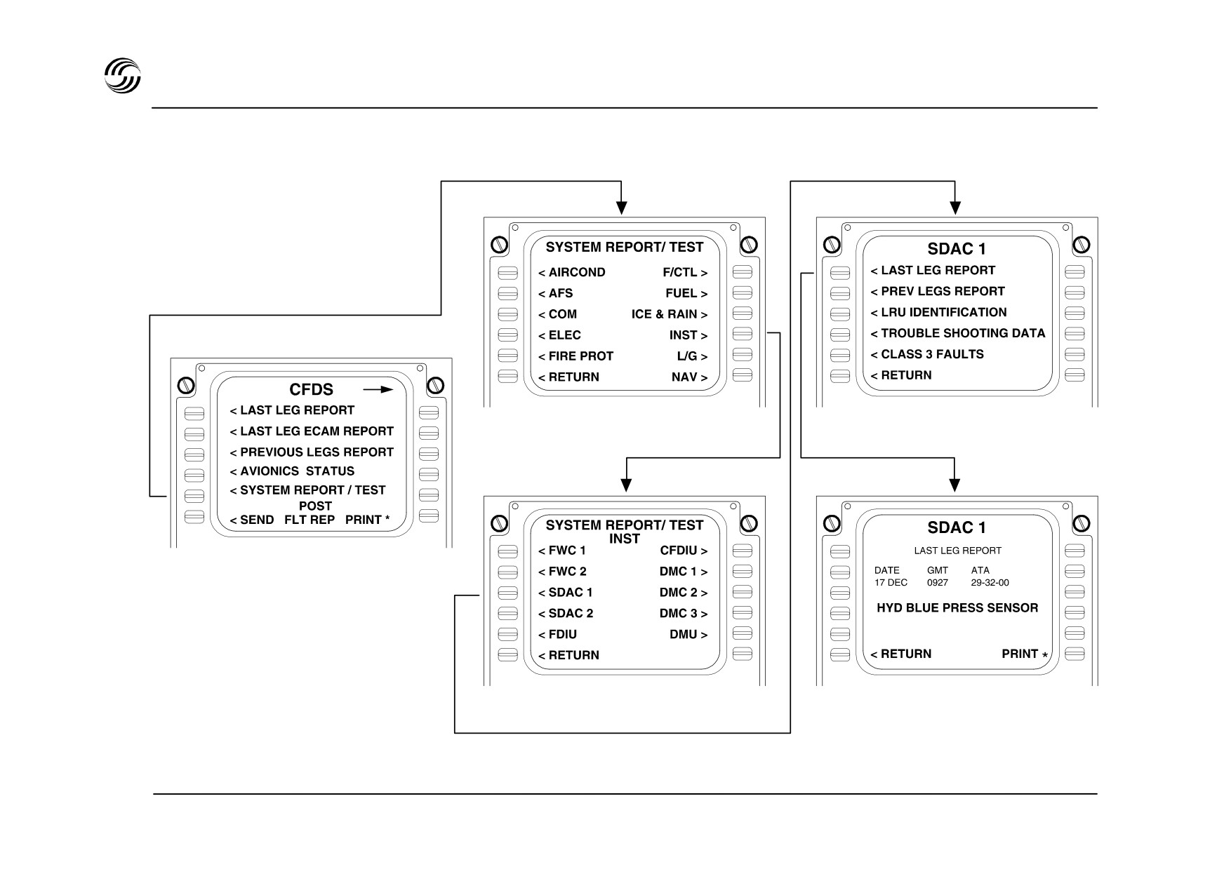
A319/A320/A321 CFDS - example of use - 3
STL 945.7136/97
14.9