Operator’s manual Machine gun, 7.62 mm, MK43 MOD 0
M
Safety information
Warnings
Keep Weapon Pointed at target - down range/limpact area.
Never stand in front of weapon or expose body or hands to breech, ejection port,
or muzzle.
Keep Safety on S until you’re ready to fire.
Always check the chamber/bore after clearing the weapon.
Check barrel bore and chamber before firing.
Change hot barrels by holdlng onto carrying handle.
(Refer to pages 61 and 84 for procedures.)
Be sure barrel lock lever Is locked down before charging and flring the gun.
Before starting Inspection, be sure to clear weapon (p 26).
If cover is opened on hot cartridge (hot barrel), an open cover cook-off could occur
and result In serious injury or death. Evacuate area for 15 minutes and then do
Immediate Action (p 32).
MK 43 MOD 0
iii
Never reload a runaway gun until it has been repaired.
Cautions
Be sure machine gun is cleared before moving it.
When removing a stuck unfired cartridge, stay clear of the muzzle. Do not allow
Do not use tip of driving spring guide assembly as a tool.
cartridge to contact any hard surface. Cartridge may fire on contact. Remove a stuck
Insert reamer carefully to prevent damage.
unfired cartridge using the same procedures for removing a stuck or ruptured
Do not get lubricant in gas system.
cartridge case.
The climate temperature in different regions will make a difference as to what
constitutes a hot gun. A hot, sunny day can cause a cookoff within 50 rounds, with
weapon and ammunition in sun.
Before field stripping, clear and check that the bolt is in forward position.
Bolt assembly is under spring tension. It can twist and injure your hand.
Barrels issued for a specific gun should not be changed from gun to gun. Each barrel
and bolt assembly should remain together as initially issued.
Only use authorized ammunition in machine gun.
Be sure Blank Firing Adaptor (BFA) is removed before firing live ammunition.
Do not fire blank ammunition towards personnel within 20 feet of muzzle. Fragments
of a closure wad or particles of unburned propellant might inflict injury within that range.
iv
US ORDNANCE
MK 43 MOD 0
v
Contents
SAFETY INFORMATION
iii
Section II. Preventive Maintenance Checks and Services(PMCS)
16
Section Ill. Operation Under Usual Conditions
21
CHAPTER 1
Assembly and Preparation for Use
21
INTRODUCTION
1
Loading Ammunition in the MK43 MOD 0
21
Section I. General Information
1
Clearing and Unloading the MK43 MOD 0
26
Scope
Initial Adjustments, Daily Checks, and Self-Test
30
Section II. Equipment Description
2
Field Zeroing
30
Equipment Characteristics, Capabilities and Features
2
Operating Procedures Immediate Action
32
Location and Description of Major Components
2
Runaway Machine Gun
32
MK43 MOD 0 Machine Gun
2
Misfire
34
CHAPTER 2
Remedial Action (Steps to take if immediate action-misfire does not work) . . . 36
OPERATING INSTRUCTIONS
10
Removing Stuck or Ruptured Cartridge Case (When round fires
Section I. Description and Use of Operator’s Controls and Indicators1 0
but cartridge case does not extract)
38
MK43 MOD 0 Machine Gun
10
Section IV. Operation Under Unusual Conditions
42
Front Sight Adjustment
14
In Extremely Cold Climate
42
Trigger Guard
15
vi
US ORDNANCE
MK 43 MOD 0
vii
In Hot, Wet Climate
43
Section IV. Cleaning and Inspection
67
In Hot, and Sandy Areas
43
Bolt Assembly and Operating Rod Assembly
67
After Exposure to Water
43
Cover Assembly and Cartridge Feed Tray Assembly
70
Barrel and Handle Assembly
72
CHAPTER 3
Trigger Mechanism Grip Assembly
77
MAINTENANCE INSTRUCTIONS
44
Receiver
79
Section I. Lubrication Guide and Instructions
44
Section V. Reassembling Machine Gun
80
Recommended Lubrication Areas
46
Forearm Grip, Sling Swivel and Bipod Assembly
80
Section II. Troubleshooting Procedures
47
Trigger Mechanism Grip Assembly
82
Introduction
47
Barrel and Handle Assembly
84
Section Ill. Field-Stripping Machine Gun Procedures
53
Cover and Cartridge Feed Tray Assembly
85
Shoulder Buttstock and Buffer Assembly
53
Bolt Assembly and Operating Rod Assembly
87
Bolt Assembly and Operating Rod Assembly
56
Shoulder Buttstock and Buffer Assembly
90
Cover and Cartridge Feed Tray Assembly
59
Assembly of Buttstock to Receiver
91
Barrel and Handle Assembly
61
Section VI. Maintenance Checklist
93
Trigger Mechanism Grip Assembly
62
Section VII. Machine Gun Check Out Procedure
94
Forearm Grip, Sling Swivel and Bipod Assembly
65
viii
US ORDNANCE
MK 43 MOD 0
ix
CHAPTER 4
Chapter 1-introduction
AMMUNITION
96
APPENDIX A
Section I. general information
REFERENCES
98
APPENDIX B
Scope
COMPONENTS OF END lTEM AND BASIC ISSUE ITEMS LISTS
100
Section I. Introduction
100
Type of Manual: Operator’s Manual.
Section II. Components of End Item
103
Model Number and Equipment Name: MK43 MOD 0 7.62-mm Machine Gun.
Section III. Basic Issue Items
104
Purpose of Equipment: The MK43 MOD 0 7.62-mm Machine Gun is a light weight
APPENDIX C
general purpose weapon for assault use. The weapon is intended for hand held or
ADDITIONAL AUTHORIZED LIST
108
blpod supported firing. The weapon is also capable of being fired from standard
Section I. Introduction
108
mounts.
APPENDIX D
EXPENDABLE/DURABLE SUPPLIES AND MATERlALS LIST
110
Section I. Introduction
110
Section II. Expendable/Durable Supplies and Materials List
112
x
US ORDNANCE
MK 43 MOD 0
1
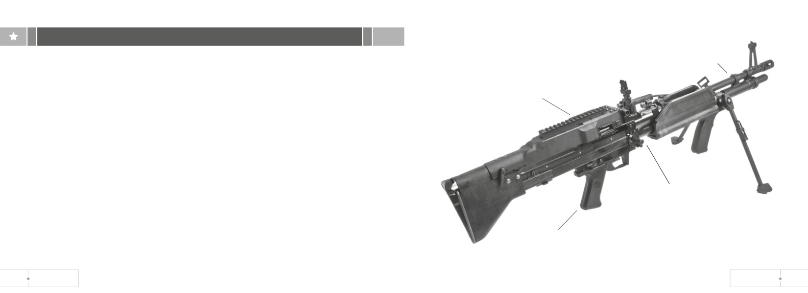
Section II. Equipment description
barrel
assembly
Equipment Characteristics, Capabilities and Features.
The MK43 MOD 0 is air-cooled and has fixed headspace allowing quick barrel
changes for cooling and maintenance when required. Two barrel assemblies are
cover assembly
issued with each gun. Barrels issued for a specific gun should not be changed
from gun to gun. Each barrel and bolt assembly should remain together as initially
received. The machine gun is gas operated and fires from the open bolt position.
Location and Description of Major Components.
MK43 MOD 0 Machine Gun
Cover Assembly. Positions and holds cartridge in place for stripping, feeding link belt
and chambering rounds.
Cocking Handle Assembly. Provides a means to manually move the bolt assembly to
cocking handle
the rear.
assembly
Trigger Mechanism and Grip Assembly. Controls the firing of the machine gun.
Barrel/Assembly. The barrel assembly houses cartridges for firing.
trigger mechanism
grip assembly
2
US ORDNANCE
MK 43 MOD 0
3
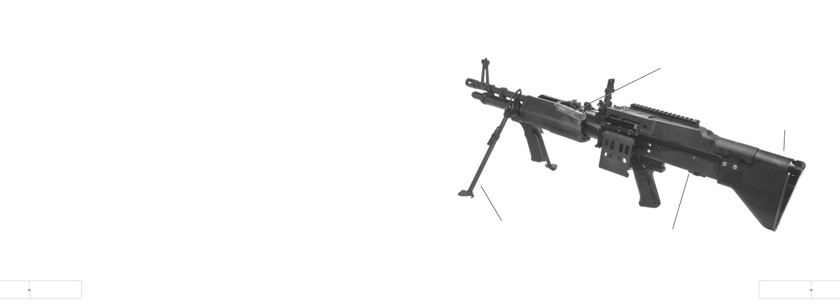
Carrying Handle Assembly. Provides a means to carry the machine gun and change
barrels with one hand. The carrying handle assembly folds left when the rear sight is
used and the machine gun is fired.
carrying handle
assembly
Receiver Assembly. Supports all major components. Houses internal parts and,
through a series of cam ways, controls operation of weapon.
Shoulder Buttstock. Provides a suitable surface to stabilize the weapon against the
shoulder
shoulder while firing the machine gun from any position except from the hip.
buttstock
Bipod Assembly. Provides a semi-stable platform when the machine gun is fired from
the prone position.
bipod assembly
receiver assembly
4
US ORDNANCE
MK 43 MOD 0
5
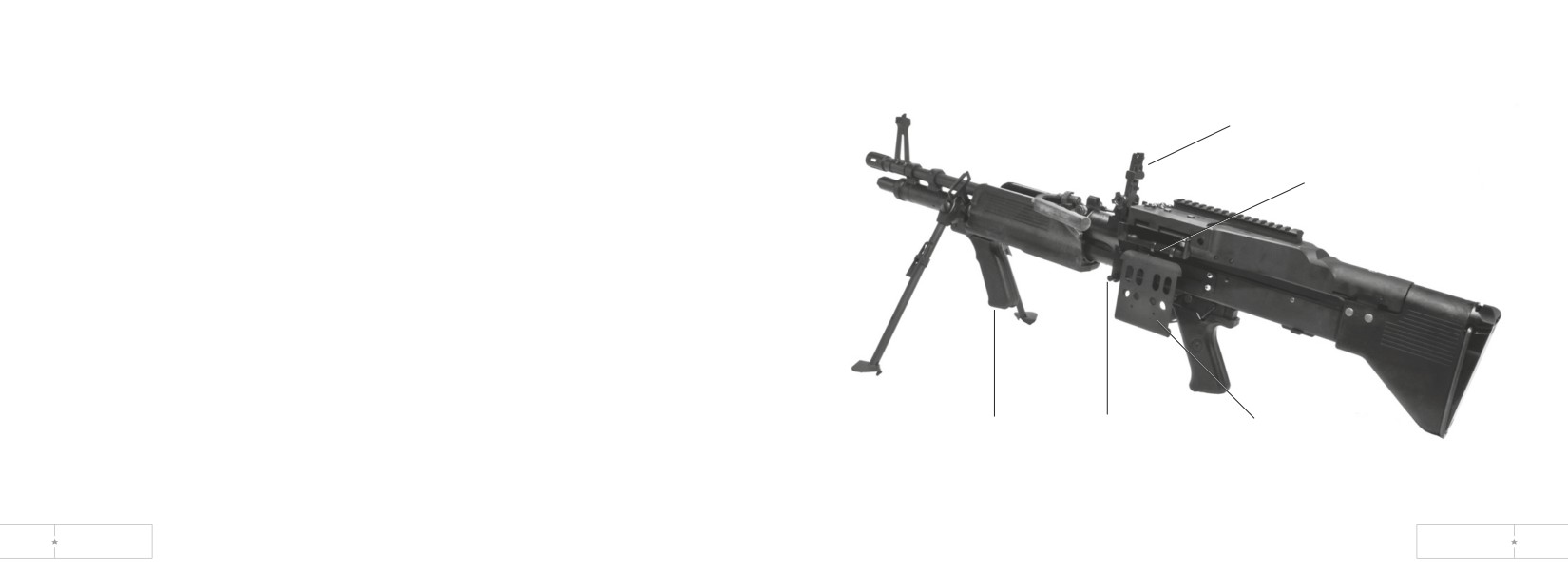
Cartridge Feed Tray Assembly. Guides cartridges for positioning and feeding.
Bandoleer Bracket Assembly. This assembly supports the ammunition bandoleer.
rear sight
Rear Sight Assembly. Provides a means to aim the machine gun at the target with
assembly
accuracy. The sigh adjusts horizontally as well as vertically.
cartridge feed
Forearm Grip Assembly. Provides a hand hold when firing from the hip or from the
tray assembly
standing or kneeling position.
Front Mounting Pin. Provides a means to attach gun to a pintle assembly.
forearm grip
front mounting
Bandoleer
assembly
pin
bracket assembly
6
US ORDNANCE
MK 43 MOD 0
7
Equipment Data.
Rifling:
MK43 MOD 0 Machine Gun
Number of lands
4
Right hand twist
One turn in 12 in. (304.8mm)
Weight
20.8 lb. (9.4 kg)
Trigger pull:
Length:
Maximum
11.5 lb (5.2 kg)
Short Barrel
37.7 in. overall (958 mm overall)
Minimum
8.0 lb (2.7 kg)
Long Barrel
42.2 in. overall (1071mm overall)
Maximum Effective Range
1100 meters
Maximum Range
3725 meters
Tracer Burn Out
900 meters or more
Rates of fire:
Sustained
100 rd per min (4 to 6 seconds between bursts)
Recommend barrel change every 6 min
Rapid
200 rd per min (2 to 3 seconds between bursts)
Recommend barrel change every 2 min
Cyclic
500-650 rounds per minute
Recommend barrel change every min
Muzzle velocity
2800 fps (853 m/sec)
Capacity of bandoleer
100 rds
8
US ORDNANCE
MK 43 MOD 0
9
CHAPTER 2-OPERATING INSTRUCTIONS
SecTION I. DESCRIPTION & USE OF OPERATOR’S CONTROLS & INDICATORS
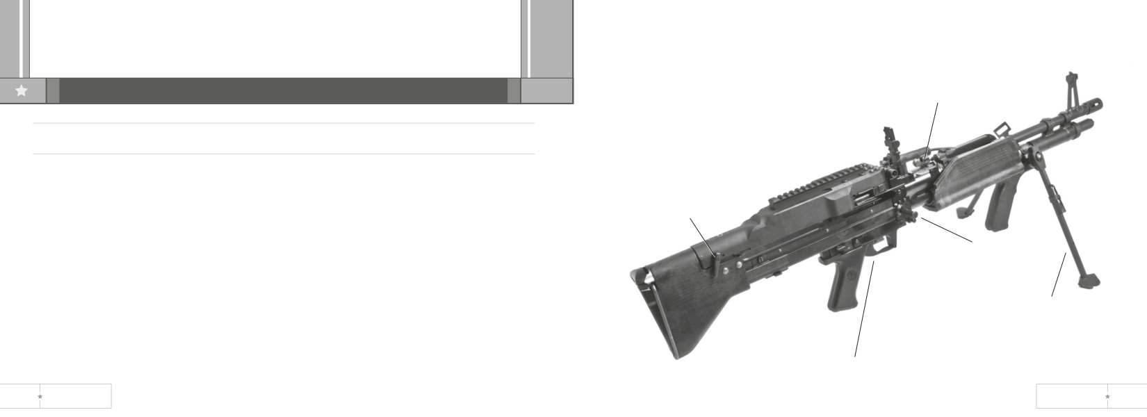
barrel lock lever
MK 43 MOD 0 Machine Gun
Cocking Handle. Pull back to move bolt rearward.
Cover Latch Lever. Holds cover closed. Pull back on lower end of latch to open.
COVER LATCH
Barrel Lock Lever. Locks barrel in place. To unlock barrel, push in on barrel lock lever
LEVER
from left side of weapon and raise lever.
Bipod Leg Lock. Depress to extend or retract bipod foot.
cocking
Trigger. Pull rearward to fire weapon. Release to stop firing.
handle
Safety Move safety up to F (fire) and down to S (safe).
bidpod leg lock
trigger
10
US ORDNANCE
MK 43 MOD 0
11
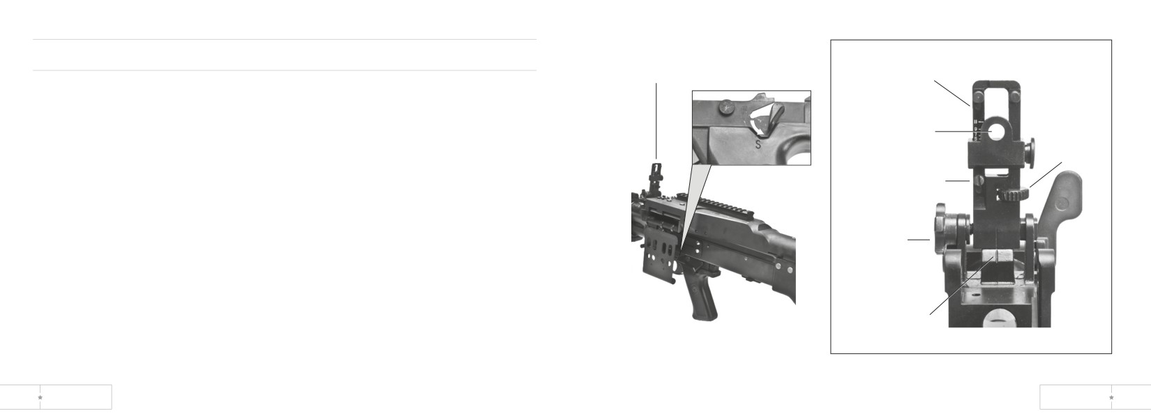
Rear Sight
REAR
SIGHT
RANGE
SCALE
Range Scale - use to judge target distance.
Scale Retaining/Adjusting Screw - locks range scale in place.
Elevating Knob - use for minor (fine) adjustments in range.
REAR SIGHT
Windage Scale - indicates left or right windage.
APERTURE
ELEVATING
Windage Knob -adjusts windage scale left or right.
KNOB
Rear Sight Aperture - lines up with front sight for long range targets.
SCALE RETAINING/
ADJUSTING SCREW
WINDAGE
KNOB
WINDAGE
SCALE
12
US ORDNANCE
MK 43 MOD 0
13
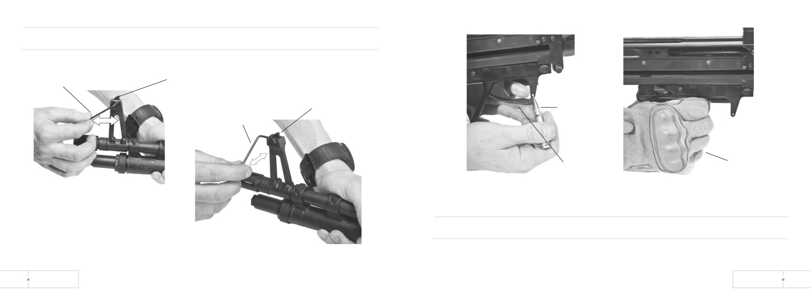
Front Sight Adjustment
elevation
combination
raise
adjustment
key
sight
windage adjustment
combination
round
key
trigger guard
mitten
elevation (vertical)
adjustment
Open Trigger Guard
1. Depress spring detent with a round or any other pointed object.
windage (horizontal)
adjustment
2. Pull trigger guard down.
14
US ORDNANCE
MK 43 MOD 0
15
Operator/Crew PMCS
Section II. preventative maintenance checks and services (pmcs)
B - Before D - During A - After
Item
Interval
No.
B
D
A
Item to be inspected and procedure
General
Always keep in mind the Cautions and Warnings when performing your before (B) or
WARNING: Before starting inspection, be sure to clear
during (D) PMCS. After you operate, perform your after (A) PMCS.
weapon (p 26)
Perform before (B) PMCS if: (1) you are the assigned opperator and the machine gun
has been stored and not used for a period of 90 days or (2) you have been issued the
1
•
MK43 MOD 0 Machine Gun Tools and Equipment.
machine gun for the first time.
Visually check for missing or damaged tools and equipment.
2
•
Barrel Assembly. Open cover, pull bolt to rear, push cocking
handle forward and lock. Close cover, place on safe (S). Tilt weapon
end to end to make sure gas piston slides freely (a clicking sound
will be heard as the piston slides in the cylinder). Run a dry swab
through the bore to remove excess lubricant or obstructions.
Equipment is NOT ready/available if: Gas piston will not slide.
Obstruction in barrel.
16
US ORDNANCE
MK 43 MOD 0
17
Operator/Crew PMCS
Operator/Crew PMCS
B - Before D - During A - After
B - Before D - During A - After
Item
Interval
Item
Interval
No.
B
D
A
Item to be inspected and procedure
No.
B
D
A
Item to be inspected and procedure
3
•
Trigger Mechanism Grip Assembly.
5
•
Gun Receiver Assembly. Check for free movement of cocking
1. Make sure that flat spring is in place (p 62).
handle. Check barrel lock lever. Make sure it locks barrel in place.
2. Check that Safety is in F position.
Equipment is NOT ready/available if: Cocking handle binds or
3. Pull bolt to the rear.
barrel is loose.
4. Move safety to S
5. Push charging handle foward and lock.
6. Pull the trigger.
6
•
MK43 MOD 0 Machine Gun. Erratic or sluggish firing may indicate
carbon build-up. Switch barrels (p 61). If firing is still erratic or
Equipment is NOT ready/available if: Weapon functions with
sluggish, field-strip the weapon and perform the necessary
safety at S.
maintenance (p 53) to complete the fire mission.
Equipment is NOT ready/available if: Weapon ceases to operate.
4
•
Cover Assembly. Lightly lubricate all moving parts before using.
18
US ORDNANCE
MK 43 MOD 0
19
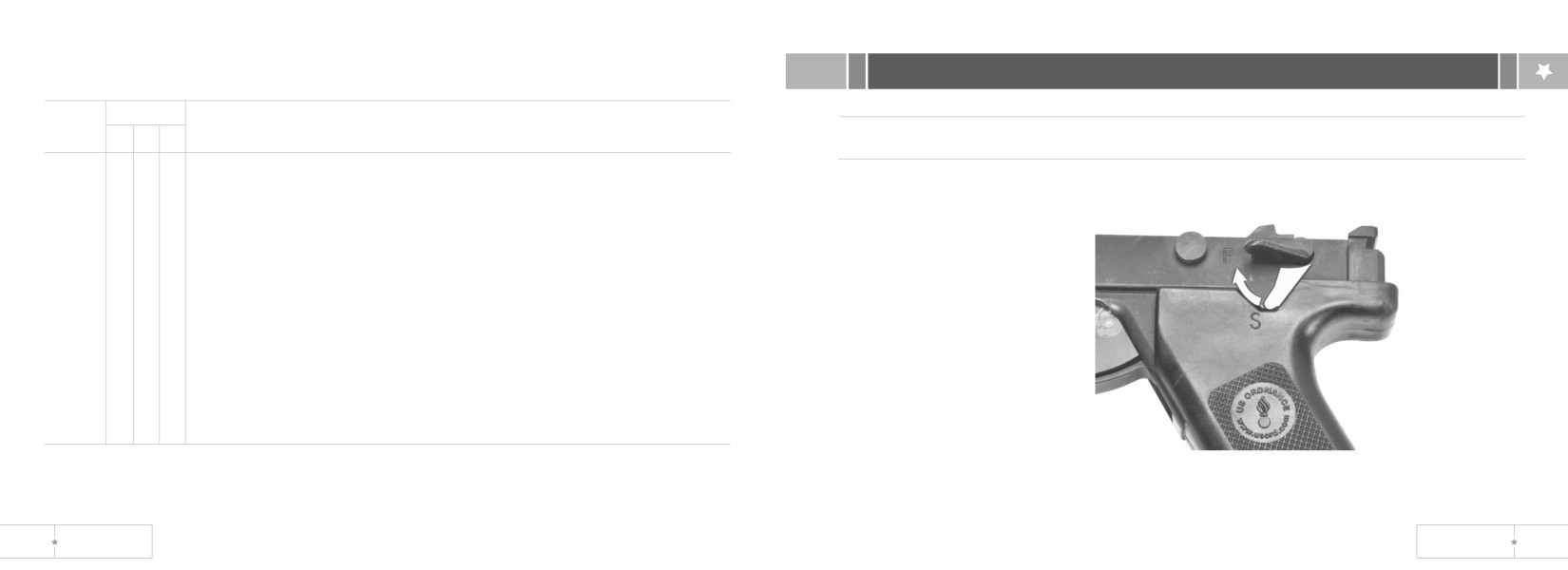
Operator/Crew PMCS
Section III. Operation Under unusual conditions
B - Before D - During A - After
Item
Interval
No.
B
D
A
Item to be inspected and procedure
Assembly and Preparation for Use
7
•
MK43 MOD 0 Machine Gun. Field-strip (p 53) clean, inspect and
Loading Ammunition in the MK43 MOD0
lubricate entire weapon (p 44).
8
•
MK43 MOD 0 Machine Gun (Inspection). Inspect operating rod
assembly and barrel assembly for burrs, cracks and chips. Make
sure the gas piston slides back and forth freely. Inspect components
of trigger assembly for wear. Check safety in S position, sear
should move slightly and in F position, sear should move freely.
Inspect breech bolt assembly for defects - e.g., cracks or chips.
Reassemble weapon and check for proper functioning.
Equipment is NOT ready/available if: Weapon fails to function
properly or has damaged or missing parts.
1. Point weapon down range.
2. Move safety to F.
20
US ORDNANCE
MK 43 MOD 0
21
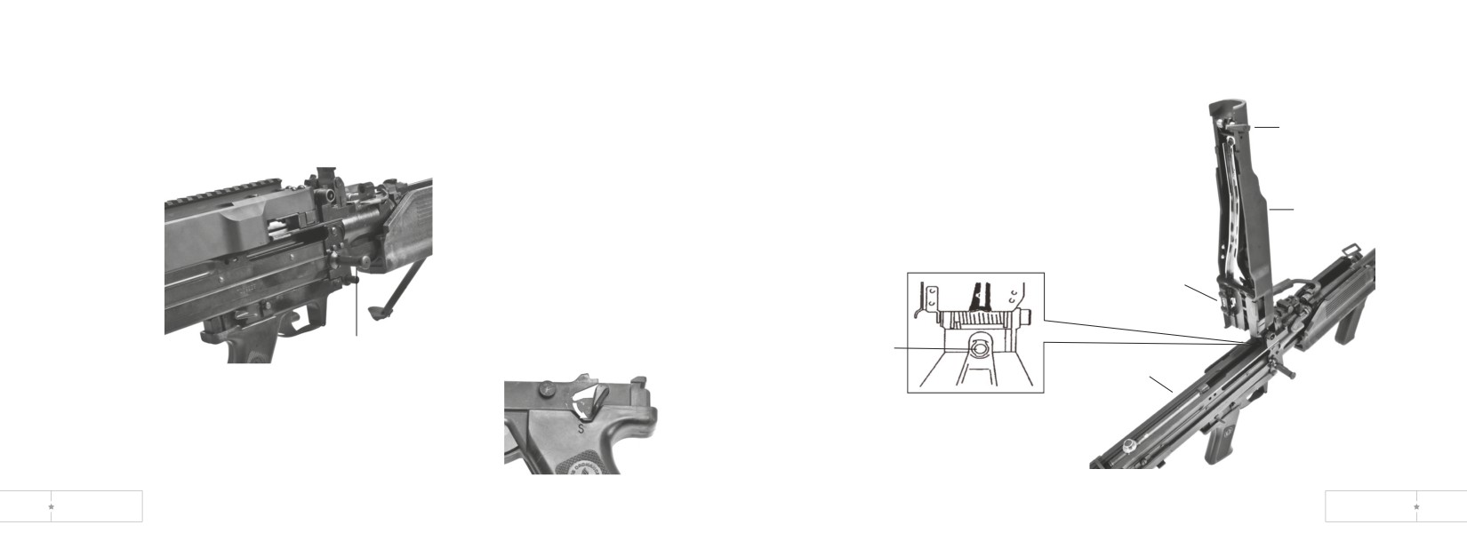
3. Pull cocking handle rearward to the charged position, then push it forward until it
5. Turn latch lever and open cover.
locks.
6. Raise cartridge feed tray and check
4. Move safety to S.
chamber for ammunition.
latch
lever
cover
cartridge
feed tray
cocking
chamber
handle
receiver
22
US ORDNANCE
MK 43 MOD 0
23
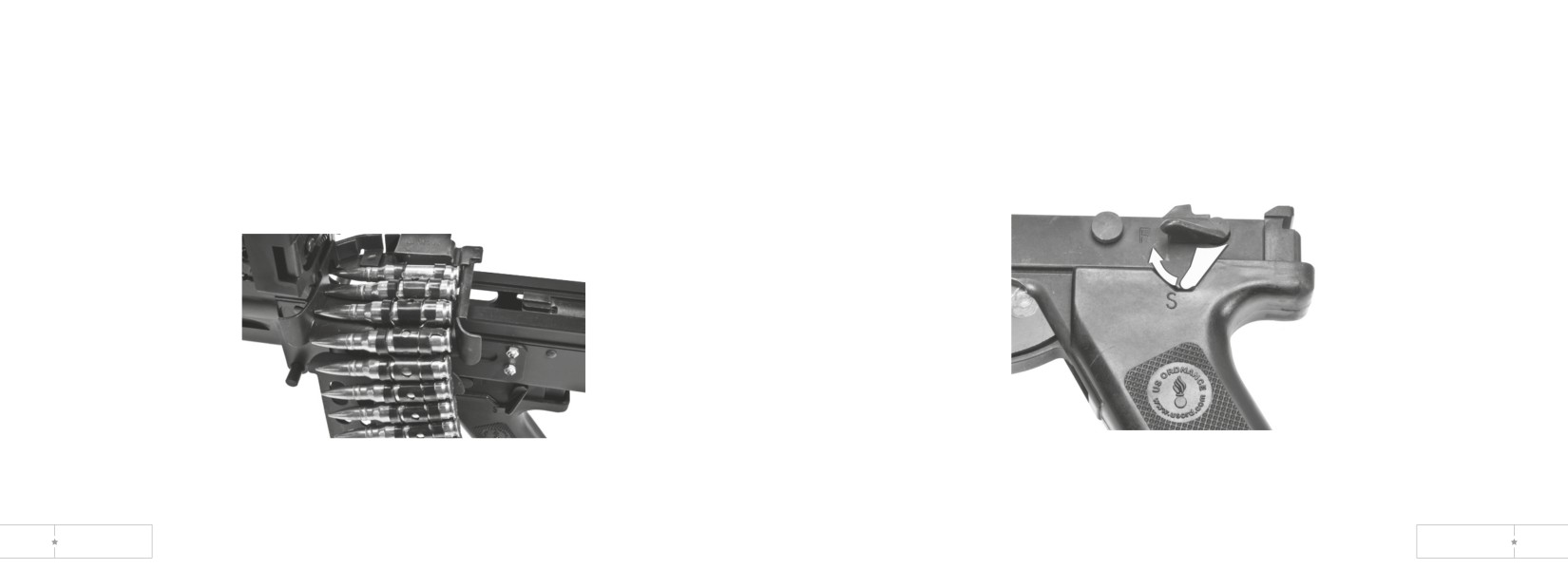
7. Lower cartridge feed tray. Place bandoleer on bandoleer bracket.
10. Move safety to F.
11. The gun is ready to fire.
8. Place ammunition on feed tray with open side of links down and with first round
in the feed groove. (Make sure cartridge retainer pawl holds ammunition link on
feed tray).
9. Close cover.
24
US ORDNANCE
MK 43 MOD 0
25
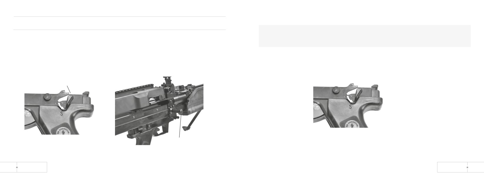
4. Move safety to S.
Clearing and Unloading the MK43 MOD 0:
WARNING: If cover is opened on hot cartridge (hot barrel), an open cover
1. Point weapon down range.
cook-off could occur and result in serious injury or death. Evacuate area for 15
2. Move safety to “F”
minutes and then do Immediate Action, (p 30).
3. Pull cocking handle rearward to the charged position then push it
5. Turn latch lever and open cover.
forward until it locks.
safety
cocking
handle
26
US ORDNANCE
MK 43 MOD 0
27
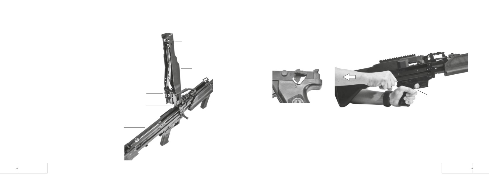
6. Remove ammunition and link belt and raise feed tray.
7. Inspect chamber. If empty, go to step 8. If a round is
chambered, see page 38 for stuck or ruptured
cartridge case and page 47 for trouble-shooting.
latch lever
cover
feed tray
trigger
chamber
receiver
8. Lower feed tray.
9. Close cover. Cover latch should catch and hold cover closed.
10. Move safety to F. Pull cocking handle rearward and hold it. Pull trigger and allow
cocking ahndle to move forward slowly.
28
US ORDNANCE
MK 43 MOD 0
29
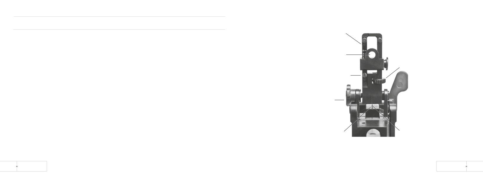
Initial Adjustments, Daily Checks, and Self-Test
RANGE
SCALE
Field Zeroing
REAR SIGHT
1. Choose a target between 300 and 700 meters.
APERTURE
ELEVATING
2. Set range scale on rear sight to 500 meters.
KNOB
3. Zero windage scale with index line.
SCALE RETAINING/
4. Aim at six o’clock on bottom of target.
ADJUSTING SCREW
5. Fire burst of 6 to 9 rounds and observe impact of burst.
6. Correct for left or right wind by adjusting windage knob. Then correct range by
adjusting elevating knob. Adjust until a burst of 6-9 rounds is on target.
WINDAGE
KNOB
7. Loosen scale retaining/adjusting screw and adjust range scale so 500 meter mark
is on top of slide.
Note
One mil is equal to one meter at 1000 meters.
WINDAGE
SCALE
index
line
30
US ORDNANCE
MK 43 MOD 0
31
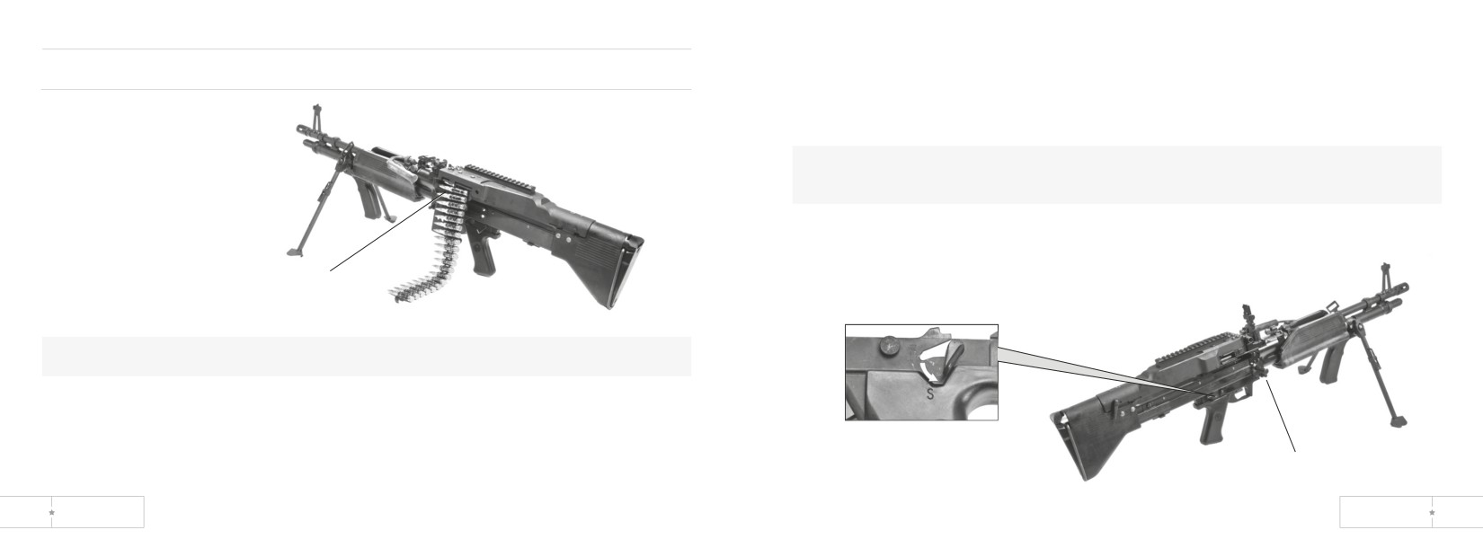
3. Pull cocking handle all the way back and hold it. Place safety to S and remove
Operating Procedures Immediate Action
link belt.
4. Clear machine gun (pg 26).
Runaway Machine Gun
5. Notify organizational maintenance for repairs.
WARNING: Never reload runaway gun until it has been repaired. Be sure machine
gun is cleared before moving it.
link belt
WARNING: Always keep machine gun pointed down range.
1. If runaway occurs (machine gun won’t stop firing), take the following actions to
correct it quickly.
move safety to s
2. Break link belt (grasp belt and twist firmly) or let machine gun fire if near end of
link belt.
cocking handle
32
US ORDNANCE
MK 43 MOD 0
33
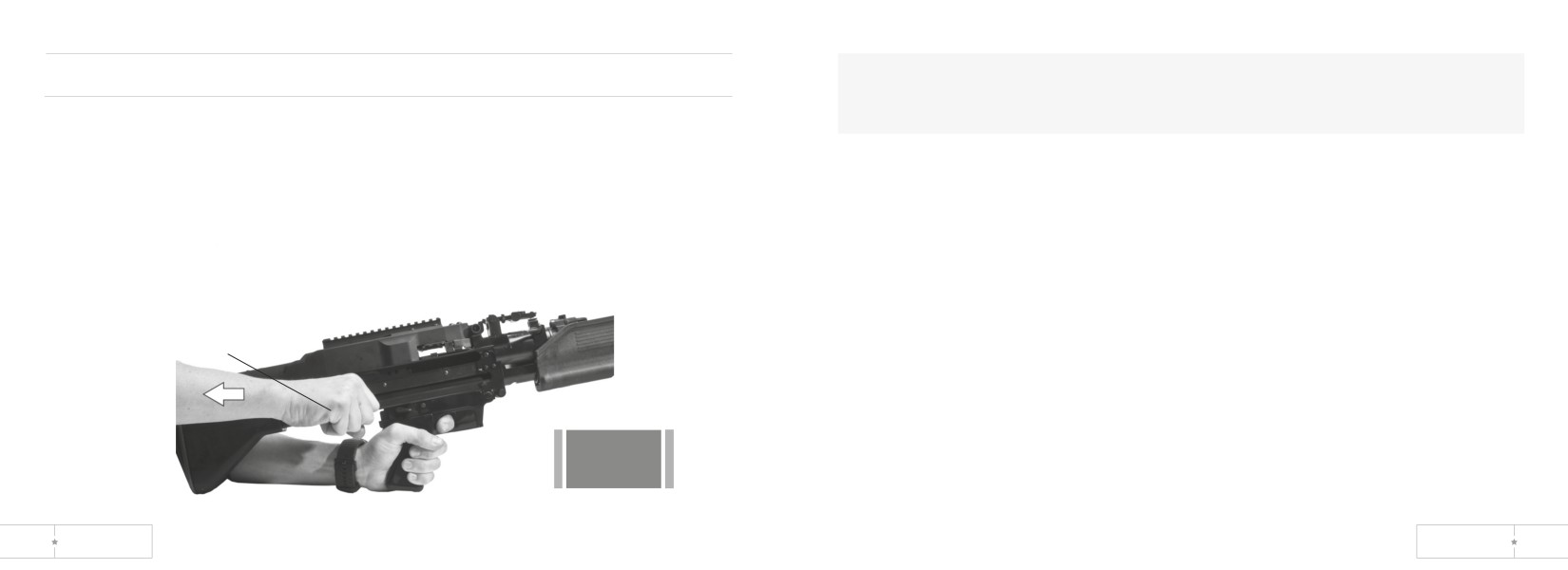
WARNING: If cover is opened on a hot cartridge (hot barrel), and open cover
Misfire
cook-off could occur and result in serious injury or death. Close cover and
If weapon stops firing before you complete your mission, take immediate action within
evacuate area for 15 minutes.
10 seconds.
4. If nothing is ejected and the barrel is hot enough to cause a cookoff (200 rounds
1. Pull cocking handle rearward.
fired within 2 minutes), wait at least 15 minutes (make sure bolt is locked rearward).
2. Check ejection port.
Repeat steps for Immediate Action.
3. If a round or cartridge case is ejected, push cocking handle forward and fire again.
5. If Immediate Action fails to remove cartridge case, take Remedial Action (pg 36).
cocking handle
Fire
again
34
US ORDNANCE
MK 43 MOD 0
35
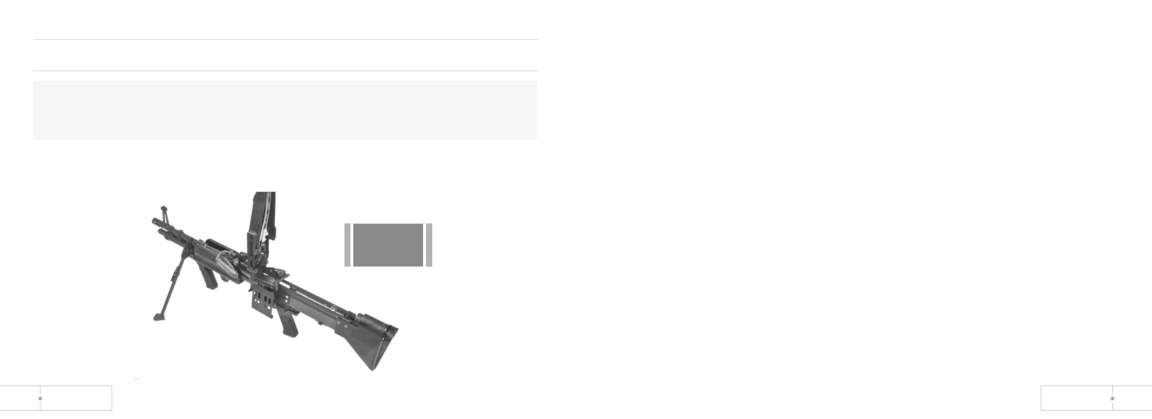
1. Keep weapon on target (down range/impact area). Clear weapon when barrel is
Remedial Action (Steps to Take if Immediate Action Misfire Fails)
cool (after 15 minutes wait) using the following steps.
2. Pull cocking handle rearward, to the charged position.
WARNING: If cover is opened on a hot cartridge (hot barrel), and open cover
3. If a round is not ejected, move safety to S.
cook-off could occur and result in serious injury or death. Close cover and
4. Open cover, remove ammunition link belt and raise feed tray.
evacuate area for 15 minutes.
5. Inspect receiver, chamber, extractor, and ammunition.
6. If a round is in chamber, lower feed tray and close cover.
7. Push cocking handle forward.
8. Move safety to F.
9. Attempt to fire.
10. If a round is fired and ejected, reload and continue to fire.
11. If a weapon does not fire or eject, clear and unload weapon, and notify
danger
organizational maintenance for repair.
36
US ORDNANCE
MK 43 MOD 0
37
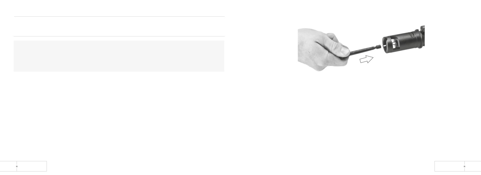
Removing Stuck or Ruptured Cartridge Case
(When Round Fires but Cartridge Case Does Not Extract)
WARNING: When removing a stuck unfired cartridge, stay clear of the muzzle.
Do not allow cartridge to contact any hard surface. Cartridge may fire on contact.
Remove a stuck unfired cartridge using the same procedures for removing a
stuck or ruptured cartridge case.
1. Pull cocking handle rearward to the charged position, and move safety to S.
2. Remove barrel. See page 53, Field Stripping.
4. Ruptured cartridge case-
a. Push ruptured cartridge extractor inside ruptured case in chamber until it seats.
3. Stuck cartridge case/unfired cartridge-Insert cleaning rod in muzzle and tap out
case/cartridge.
38
US ORDNANCE
MK 43 MOD 0
39
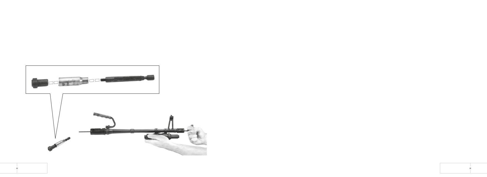
b. Lightly tap out ruptured cartridge with cleaning rod.
5. Install barrel. See Reassembly on page 84.
c. Remove extractor from cartridge case.
6. Close cover.
d. Unscrew extractor tool and remove cartridge case. Reassemble tool.
7. Hold cocking handle rearward.
8. Move safety to F.
9. Pull trigger and ease cocking handle forward.
10. Once weapon is cleared, do not move safety to S when bolt is forward.
Leave safety at F.
40
US ORDNANCE
MK 43 MOD 0
41
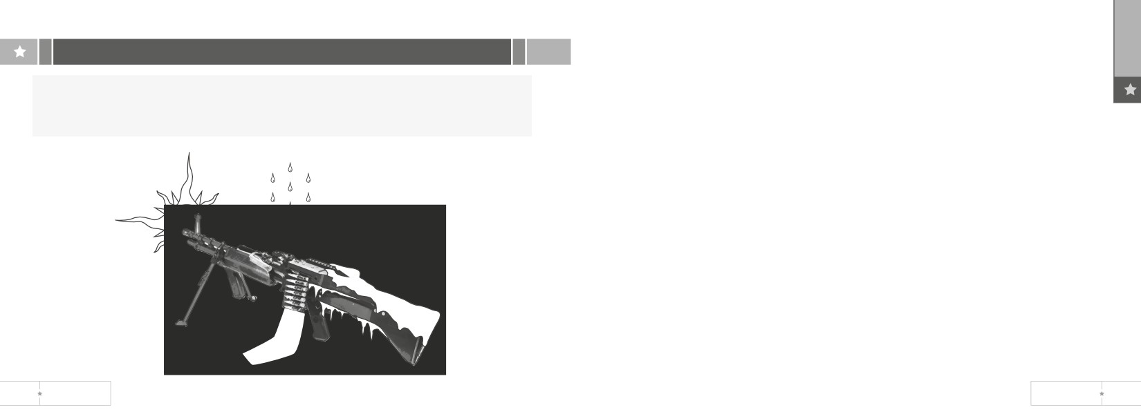
In Extremely Cold Climate:
section IV. Operation under unusual conditions
Lubricate according to Lube Guide (pg 44). Keep weapon free of moisture.
WARNING: The climate temperature in different regions will make a difference
In Hot, Wet Climate:
as to what constitutes a hot gun. A hot, sunny day can cause a cookoff within 60
Lubricate and inspect more frequently. Use a light coating of lubricant and keep
rounds, if the weapon and ammunition are left in the direct sun.
weapon dry.
In Hot, and Sandy Areas:
Inspect daily and clean frequently. Wipe lubricant from exposed surfaces and keep
sand out of parts. Cover weapon as much as possible.
After Exposure to Water:
First make sure weapon is dry before lubricating. Then disassemble,
clean, lubricate, and reassemble as soon as possible.
42
US ORDNANCE
MK 43 MOD 0
43
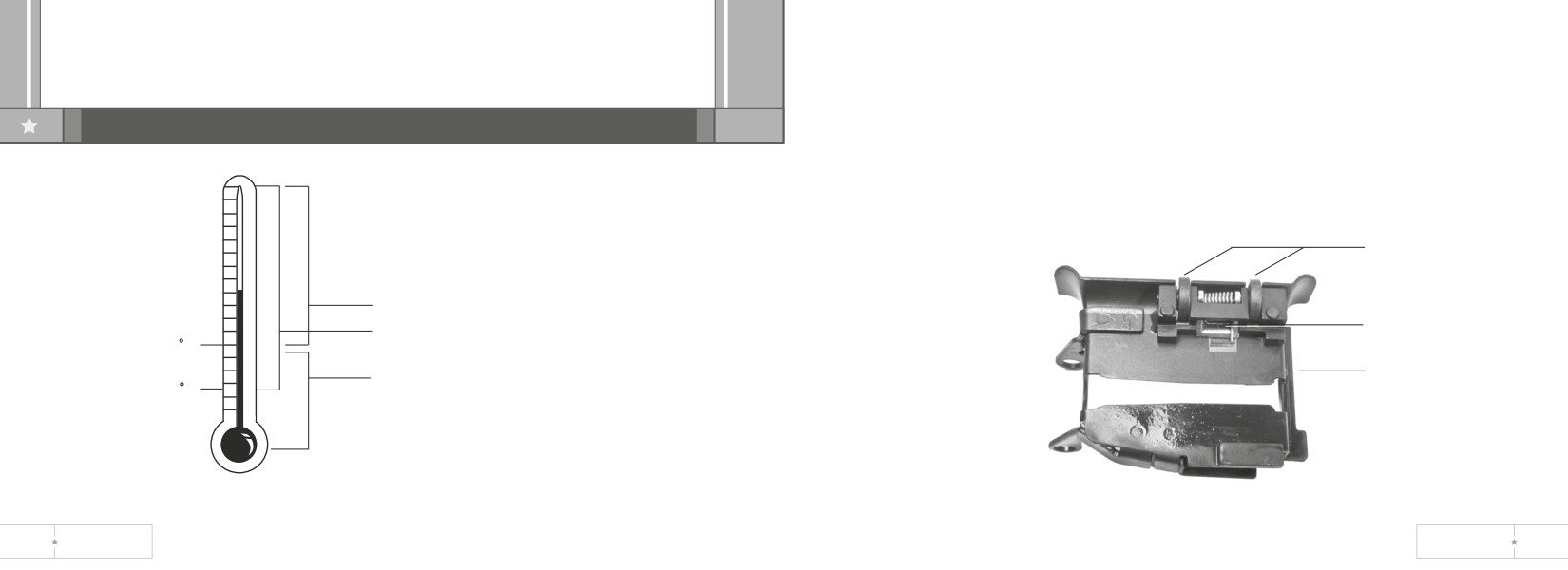
1. Under all but the coldest arctic conditions, LSA or CLP can be used on your
chapter 3-Maintenance Instructions
machine gun. Remember to remove excessive oil from the bore before firing.
2. Lightly Lube-A film of oil barely visible to the eye.
section I. Lubrication Guide and Instruction
3. Generously Lube-Heavy enough so that It can be spread with the finger.
4. External Surfaces. Put lubricant (item 1, 2 or 3, a p D) on a clean swab (item 5, app
D) and generously lubricate alI shaded areas. Lightly lubricate all other areas
except rubber-coated parts.
rollers
LSA - Lubricating Oil
pawl
CLP - Lubricating Oil, Semifluid Weapons
0 F
Between 0°F And -35°F Either CLP Or Law
feed tray
LAW - Lubricating Oil, Weapons
-35 F
44
US ORDNANCE
MK 43 MOD 0
45
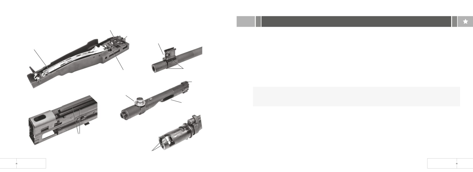
Recommended Lubrication Areas
section II. Troubleshooting procedures
front cartridge guide
Introduction
roller
The table lists the common malfunctions which you may find during the operation
feed cam
or maintenance of the machine gun or its components. You should perform the test/
inspections and corrective actions in the order listed.
rails
This manual cannot list all malfunctions that may occur nor all tests or inspections and
rear cartridge
corrective actions. If a malfunction is not listed or is not corrected by listed corrective
guide
locking
actions, notify your supervisor.
lug
roller
WARNING: Keep weapon pointed at target impact area. Never stand in front of
weapon or expose body or hands to breech, ejection port, or muzzle.
camming recess
receiver
rails
camming locking surfaces
46
US ORDNANCE
MK 43 MOD 0
47
Malfunction
Test or Inspection
Corrective Action
Malfunction
Test or Inspection
Corrective Action
Cook Off*
Hot Barrel- If you have fired 200
Cool weapon for 15
Failure to Extract
Broken extractor or spring.
Notify organizational
or more rounds within 2 minutes
minutes
maintenance.
(rapid rate of fire), barrel will be
hot enough to cause cook off.
Short recoil.
Clean gas port,
piston, gas cylinder,
operating rod, and
Failure to Fire
Check ammunition.
Replace faulty
chamber (73-76, 79).
ammunition.
Dirty ammunition or chamber.
Clean chamber
Check for broken or damaged
and/or use new
firing pin.
Notify
ammunition.
organizational
Check for weak or broken firing
mainentance.
Sluggish Operation
Friction from dirt, carbon, burrs, or
Clean/lubricate or
pin spring, guide assembly, or
lack of lubrication.
notify organizational
compression spring.
mainentance.
Wadding and
Manually charge weapon (if firing
Clean/lubricate or
Unburned Powder
blanks).
notify organizational
*COOKOFF - A misfire of a chambered round caused by the weapon overheating.
mainentance.
48
US ORDNANCE
MK 43 MOD 0
49
Malfunction
Test or Inspection
Corrective Action
Malfunction
Test or Inspection
Corrective Action
Failure to
Ruptured cartridge case.
Remove (pg 38).
Failure to Eject
Frozen or damaged ejector
Notify organizational
Chamber
spring.
maintenance.
Carbon build-up in gas cylinder.
Remove carbon.
Short recoil.
Clean gas port,
Carbon build-up in receiver
Remove carbon.
piston, gas cylinder,
assembly.
chamber, and
operating rod tube
Damaged round.
*Remove round and
(pg 73-76 & 79).
recharge weapon.
Failure to Cock or
Operating rod sear notch or sear
Notify organizational
Dirty chamber.
Clean or replace
Runaway Gun
worn.
maintenance.
barrel.
Sear plunger or spring broken or
Notify organizational
missing.
maintenance.
* Dispose of damaged round according to range SOP.
50
US ORDNANCE
MK 43 MOD 0
51
Malfunction
Test or Inspection
Corrective Action
section III. Field-stripping machine gun procedures
Failure to Feed
Insufficient gas pressure (short
Clean gas system,
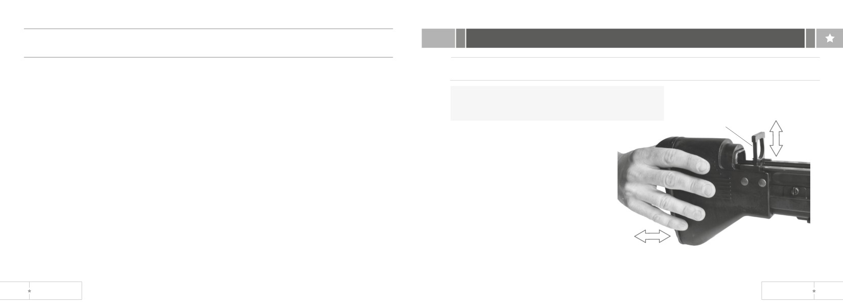
Shoulder Buttstock and Buffer Assembly
recoil).
barrel, chamber and
socket (p 73-76).
WARNING: Before field stripping, clear and
verify that the bolt is in the forward position.
Improper lubrication.
Lubricate as
yoke
neccessary (44-46).
1. Clear the weapon.
Defective ammunition or links.
Use new ammunition
2. Close cover.
belt.
3. Hold cocking handle rearward.
4. Move safety to F.
Ammunition belt installed wrong.
Install with open side
of link down (p 24).
5. Pull trigger and ease cocking
handle forward slowly. The
Damaged or weak operating
Notify organizational
breech bolt should now be in
parts.
maintenance.
the forward position.
6. Open cover.
Obstruction in receiver assembly.
Remove.
7. Push the buttstock forward in
the direction shown and remove the yoke.
52
US ORDNANCE
MK 43 MOD 0
53
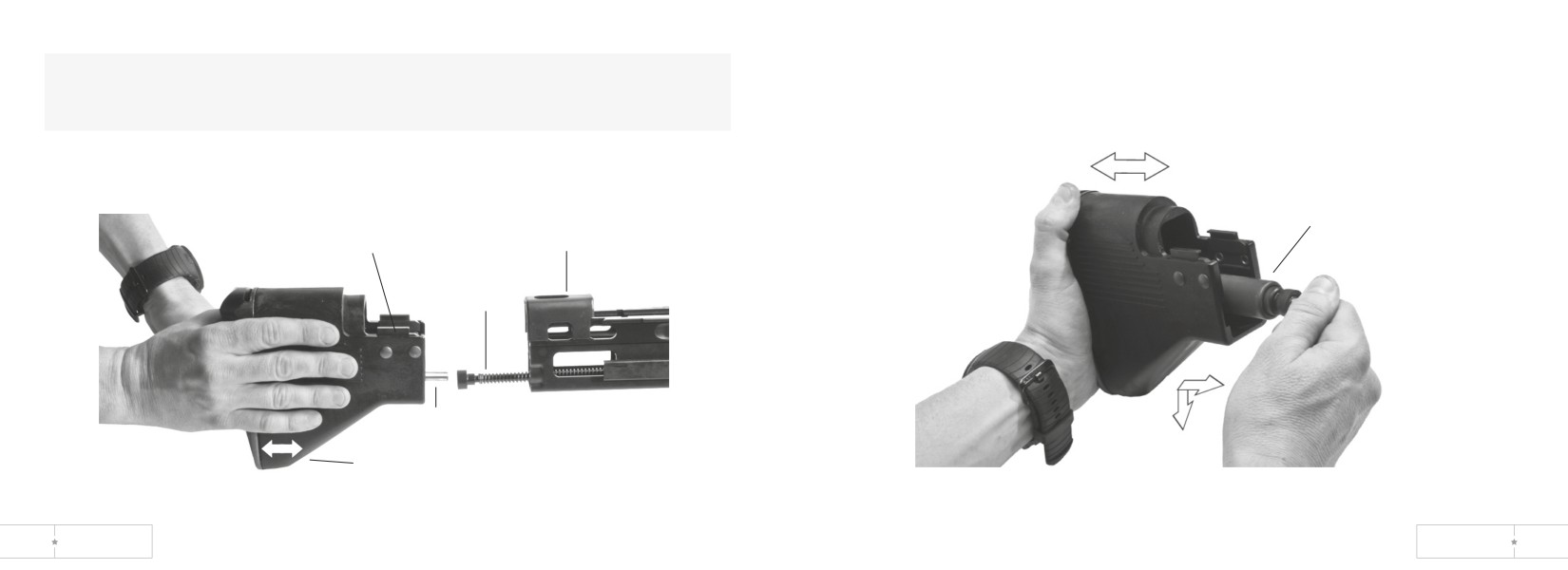
WARNING: Drive spring and drive spring guide are under spring tension. These
10. Remove the buffer assembly from the buttstock as shown.
parts may eject when the buttstock is being removed from the receiver. Avoid
exposing your body to ejection parts.
8. Slide the buttstock off the end of the receiver.
9. Remove the drive spring and drive spring guide from the receiver.
buffer
assembly
buffer assembly
receiver
drive spring
drive spring
guide
buttstock
54
US ORDNANCE
MK 43 MOD 0
55
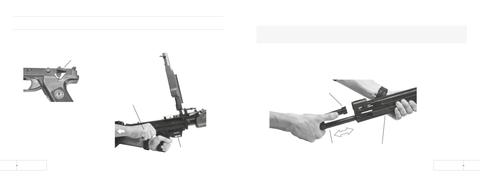
3. Remove bolt assembly and operating rod assembly as a unit.
Bolt Assembly and Operating Rod Assembly
WARNING: Bolt assembly is under spring tension. It can twist and injure
1. Move safety to F.
your hand.
2. Pull trigger and hold it while pulling cocking handle rearward.
safety
bolt assembly
cocking
handle
operating rod
receiver
trigger
56
US ORDNANCE
MK 43 MOD 0
57
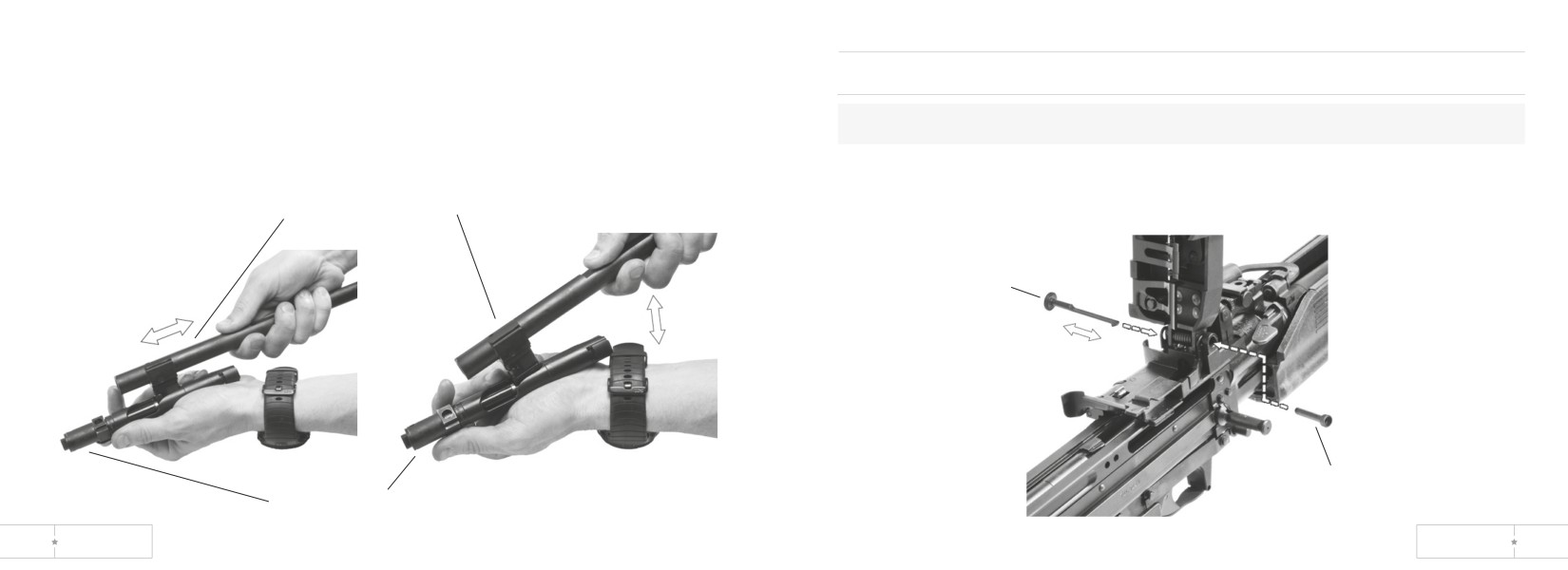
4. Push operating rod assembly toward rear of slot in bolt assembly.
Cover and Cartridge Feed Tray Assembly
5. Separate operating rod assembly from bolt assembly.
CAUTION: Do not use tip of driving spring guide assembly as a tool.
1. Use a round (cleaning rod) or similar item to unlatch hook of hinge pin latch.
Remove hinge pin latch and cover hinge pin.
operating rod assembly
hinge pin
latch
cover hinge
pin
bolt assembly
58
US ORDNANCE
MK 43 MOD 0
59
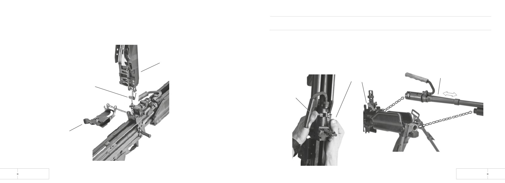
2. Remove cover assembly, torsion spring and cartridge feed tray assembly.
Barrel and Handle Assembly
1. Push in spring detent and raise barrel lock lever.
2. Slide out barrel and handle assembly to remove.
cover assembly
barrel lock
barrel and handle
lever
assembly
torsion
spring
spring
detent
cartridge feed
tray assembly
60
US ORDNANCE
MK 43 MOD 0
61
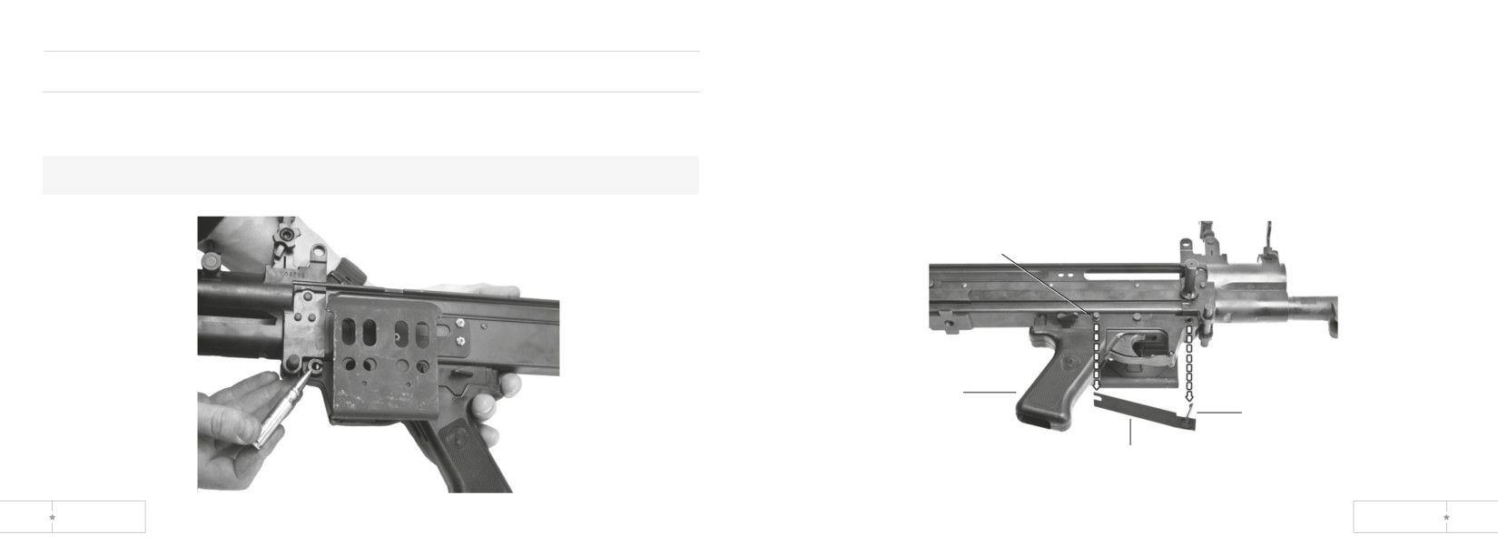
2. Grasp the flat spring on the right side of the grip assembly and pull the latch from
Trigger Mechanism Grip Assembly
the front pin.
3. Slide the slotted end of the spring from the grooved pin.
1. Use cleaning rod or similar item to push the latch in the head of the front pin to
disengage it.
CAUTION: Do not use tip of driving spring guide assembly as a tool.
grooved pin
grip
assembly
latch
assembly
flat
spring
62
US ORDNANCE
MK 43 MOD 0
63
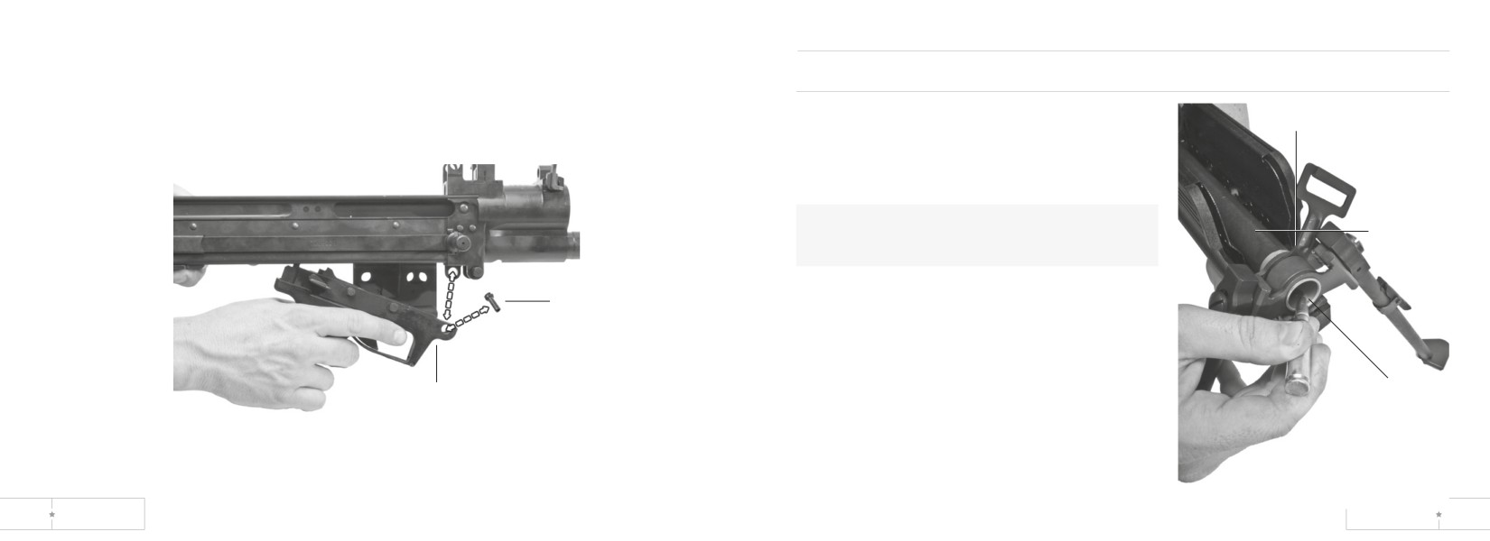
4. Push out front pin.
Forearm Grip, Sling Swivel, and Bipod Assembly
5. Slide trigger mechanism grip assembly forward and pull out.
forearm
1. Insert the end of the punch in the grip access
grip ring
hole and push down on the spring detent.
2. Slide the forearm grip, sling swivel and bipod
assembly forward.
guide
CAUTION: Do not use tip of driving spring
tube
guide assembly as a tool.
front
pin
trigger mechanism
Spring
grip assembly
detent
64
US ORDNANCE
MK 43 MOD 0
65
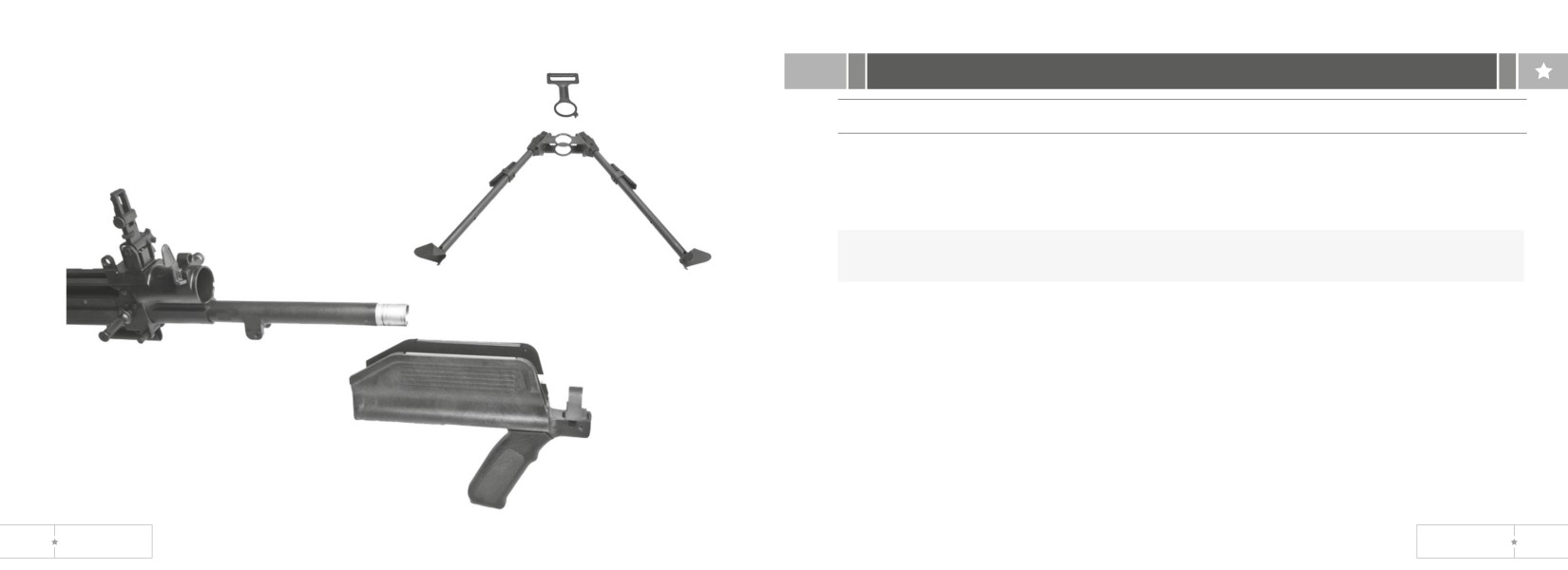
3. Remove forearm grip assembly, sling swivel
section IV. Cleaning and Inspection
and bipod assembly from the guide tube.
Bolt Assembly and Operating Rod Assembly
4. Separate sling swivel and bipod assembly
from the forward grip ring of the forearm grip
Inspect and Clean Bolt Assembly
assembly.
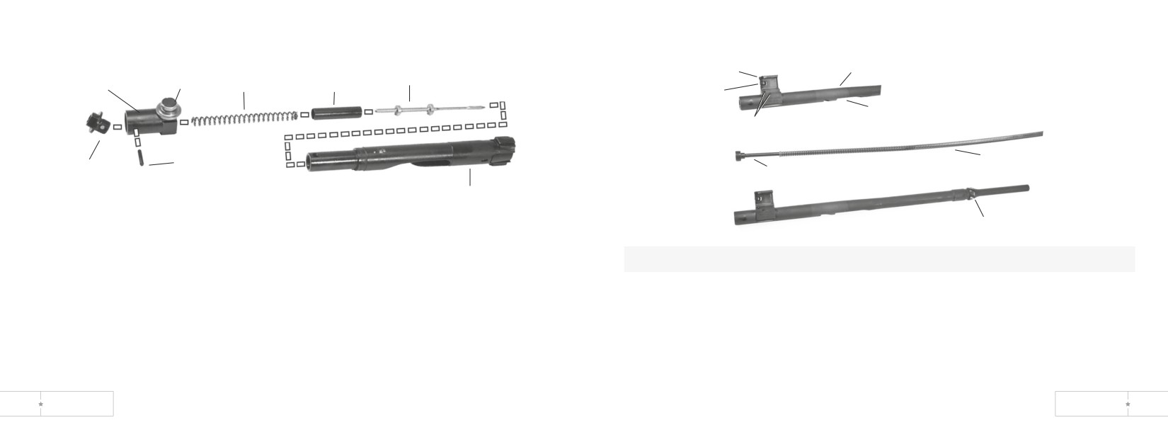
I. Inspect bolt assembly for burrs and cracks.
2. Make sure roller operates freely and is not cracked.
NOTE: Rotate cam actuator assembly so holes line up with headless straight pin.
Use reamer of combination wrench to remove or replace headless straight pin.
3. Remove headless straight pin and unscrew bolt plug assembly. Remove cam
actuator assembly from breech bolt. Separate spring, guide, and firing pin.
4. Make sure spring is not kinked.
5. Inspect threads on bolt plug assembly and in breech bolt for damage.
6. Clean powder fouling, corrosion, and dirt from all parts.
66
US ORDNANCE
MK 43 MOD 0
67
yoke
operating rod
cam
firing pin
roller
spring
guide
actuator
roller
sear notch
pins
operating rod drive
headless
bold plug
spring
straight pin
drive spring guide
assembly
bolt assembly
fluted carbon remover
NOTE: Use fluted carbon remover to clean inside of receiver (p 81).
7. Drop firing pin into breech bolt. Assemble and drop spring and guide into breech bolt.
Inspect and Clean Operating Rod Assembly
8. Assemble cam actuator assembly on breech bolt with roller to front. Screw in bolt
plug assembly and align three holes. Insert headless straight pin. Make sure cam
1. Inspect operating rod, yoke, sear notch, pins, and drive spring guide for burrs,
actuator assembly rotates freely when headless straight pin is fully seated.
cracks and chips.
2. Inspect operating rod drive spring for tension, kinks, breaks and wear.
3. Make sure roller operates freely.
4. Clean power fouling, corrosion, and dirt from all parts.
68
US ORDNANCE
MK 43 MOD 0
69
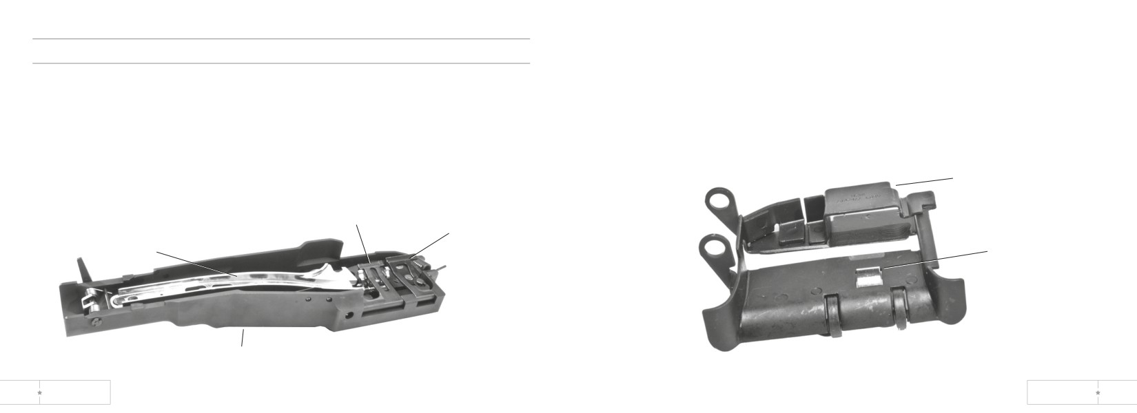
Inspect and Clean Cartridge Feed Tray Assembly
Cover Assembly and Cartridge Feed Tray Assembly
1. Inspect for burred, cracked, missing, or loose parts.
Inspect and Clean Cover Assembly
2. Check that feed tray fits on receiver and that feed pawl works properly and rollers
turn freely.
1. Inspect cover assembly for bent, burred, cracked, loose, or missing parts.
3. Clean corrosion and dirt from all areas.
2. Check spring action of front and rear guides, feed pawls (beneath the cartridge
guides), and feed cam assembly.
4. Remove lubricant from top surfaces of feed tray if gun is to be fired.
3. Make sure feed cam assembly is secure and operates freely.
4. Clean powder fouling corrosion, and dirt from all areas.
cartridge feed
tray assembly
rear cartridge
guide
front cartridge
guide
feed cam
feed pawl
cover assembly
70
US ORDNANCE
MK 43 MOD 0
71
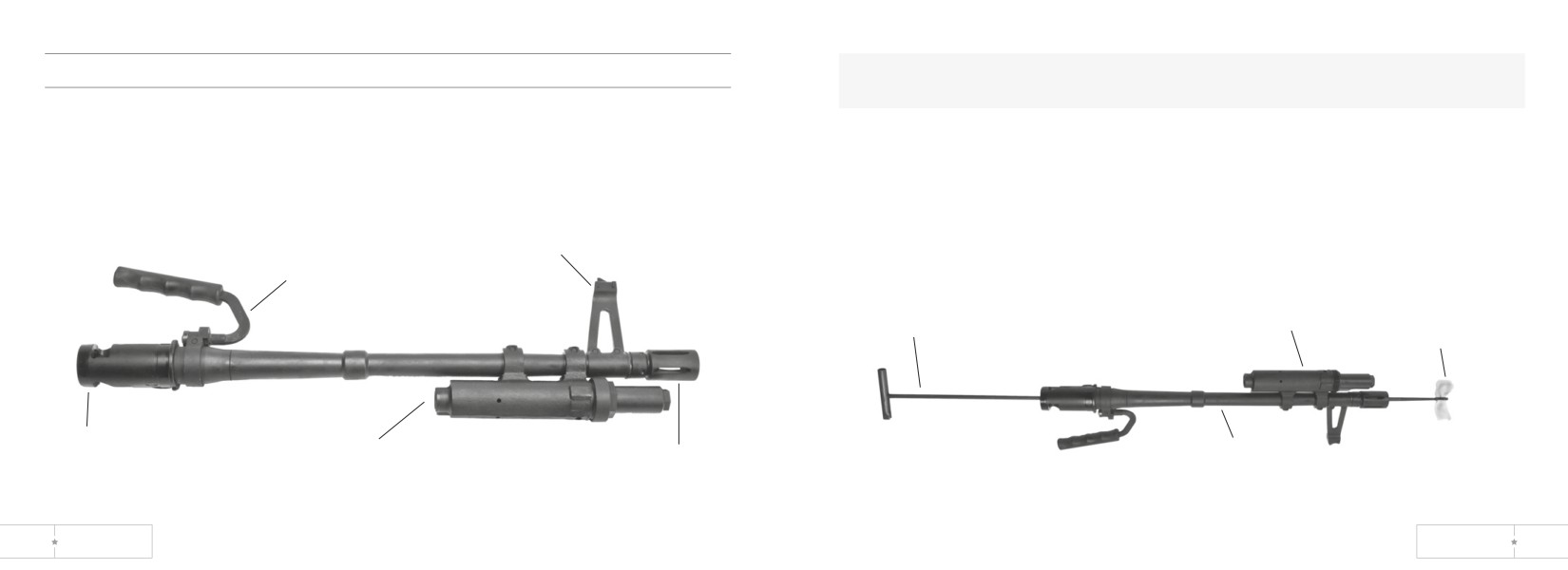
Barrel and Handle Assembly
WARNING: Barrels issued for a specific gun should not be changed from gun to
gun. Each barrel and bolt assembly should remain together as Initially issued.
Inspect Barrel
4. To clean barrel, keep barrel and handle assembly upside down to keep gas
1. Check for burrs, cracks and wear especially in the barrel socket area.
system dry.
2. Make sure sight and flash suppressor are tight.
5. Run a clean rod with swab (item 5, app D) saturated with lubricant through bore.
3. Make sure handle is secure but turns freely.
Leave bore wet.
sight
handle
cleaning
rod
gas cylinder
swab
socket
barrel
gas cylinder
flash
extension assembly
suppressor
72
US ORDNANCE
MK 43 MOD 0
73
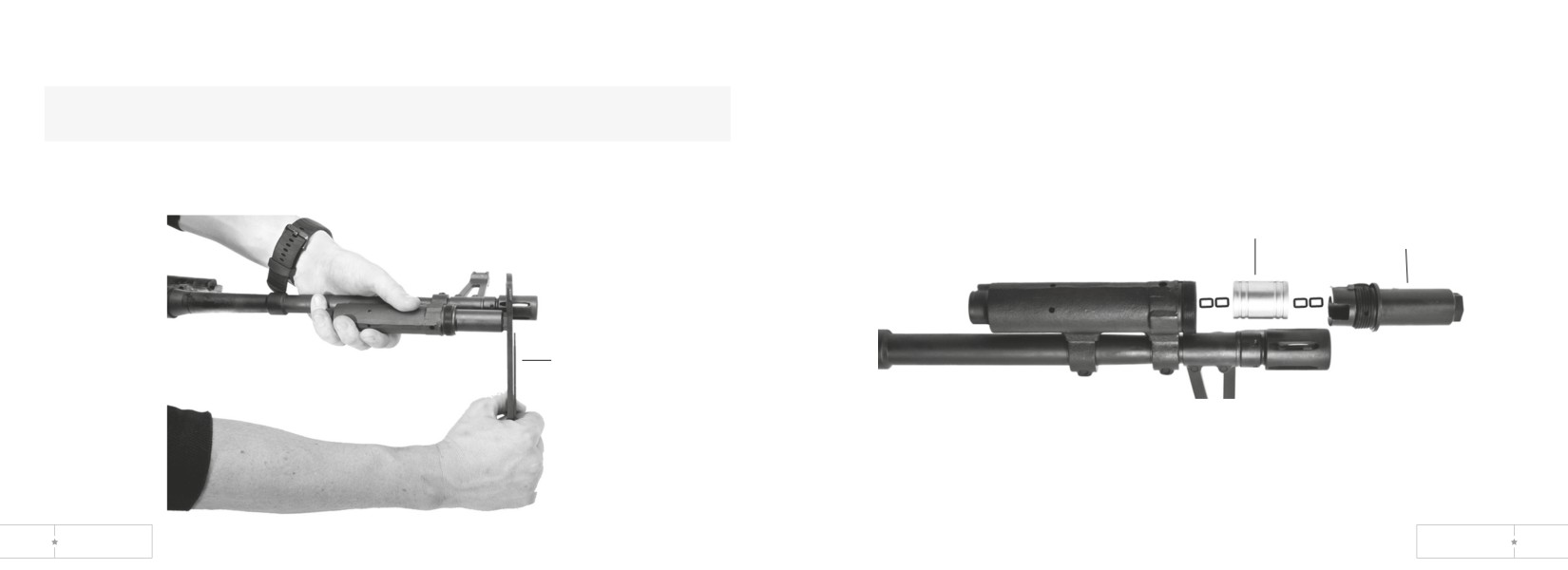
Inspect and Clean Gas System
2. Disassemble gas cylinder extension assembly with combination wrench. If gas
cylinder extension assembly is difficult to move, add a drop of lubricant where the
NOTE: Gas piston clicks when barrel is tilted. Take gas system (gas cylinder)
two protrusions contact the serrated lock nut and try again.
apart only when you don’t hear a click.
3. Clean extension vent hole with safety wire.
1. Use combination wrench and clean swab item 5, app D) to clean powder fouling,
corrosion, and dirt from alI parts.
gas cylinder
gas piston
extension assembly
combination
wrench
74
US ORDNANCE
MK 43 MOD 0
75
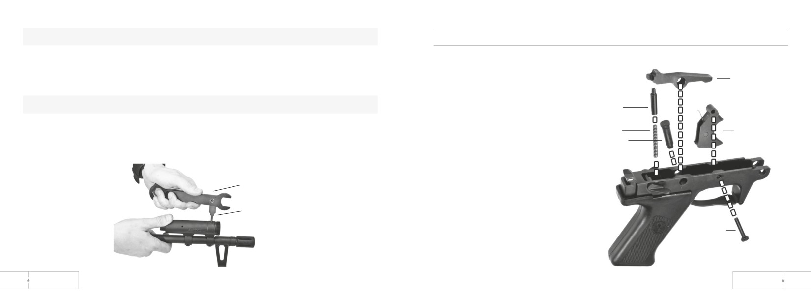
CAUTION: Insert reamer carefully to prevent damage.
Trigger Mechanism Grip Assembly
4. Clean gas port, gas piston holes, and gas cylinder vent hole with reamer portion
Inspect and Clean Trigger Mechanism Grip Assembly
of wrench.
5. Bottom the reamer in the gas port to make sure you have removed all carbon.
sear
Run small arms cleaning brush (bore) through bore to remove carbon deposits.
CAUTION: Do not get lubricant in gas system.
sear
plunger
6. Reassemble gas system (gas cylinder).
spring
trigger
7. Tighten gas cylinder extension assembly with wrench. Do not over-tighten. Then
sear pin
loosen the gas cylinder extension assembly 2 or 3 clicks.
combination
wrench
reamer
1. Hold down on sear and remove sear pin.
2. Remove sear, sear plunger and spring.
trigger
3. Remove trigger pin and trigger.
pin
4. Clean powder fouling, corrosion,
and dirt from all areas.
76
US ORDNANCE
MK 43 MOD 0
77
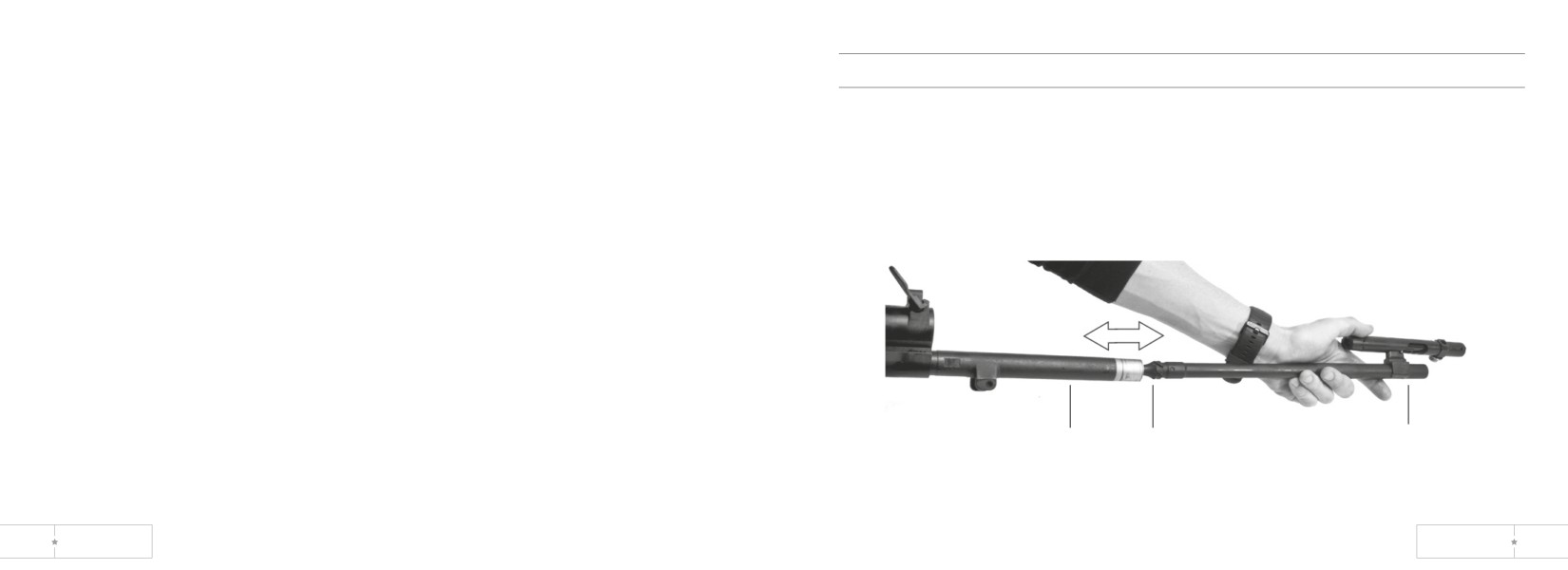
5. Inspect sear for chips, cracks, and signs of wear.
Receiver
6. Inspect sear plunger and spring for signs of wear.
7. Position trigger in grip. Align holes and insert trigger pin through the right side of
Inspect and Clean Receiver
grip and secure trigger.
1. Clean powder fouling, corrosion, and dirt from all areas.
8. Insert spring and sear plunger into hole. Position sear and apply slight pressure to
2. When weapon is disassembled, use fluted end of operating rod assembly to
align holes. Insert sear pin through left side of grip and secure sear.
remove carbon from (operating rod) guide tube.
9. Check safety:
3. Check receiver rails for burrs and wear.
• F-Sear moves freely.
4. Check that cocking handle moves freely.
• S-Sear moves slightly.
guide
fluted carbon
operating rod
tube
remover
78
US ORDNANCE
MK 43 MOD 0
79
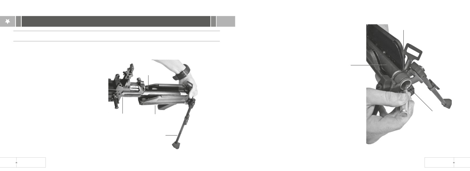
section V. reassembling machine gun
forearm
grip ring
Forearm Grip, Sling Swivel and Bipod Assembly
1. Position forearm grip under the
guide tube of assembly. Push
guide
assembly upwards over the
tube
guide tube and slide the assembly
guide
rearward until the forearm tabs
tube
engage the receiver grooves.
2. Position sling swivel and
bipod assembly in line with
forward grip ring.
3. Slide forearm grip assembly,
4. Depress spring detent with punch or
sling swivel and bipod assembly
receiver
forearm grip
Spring
suitable tool.
onto guide tube end.
assembly
assembly
detent
5. Slide forearm grip ring onto guide tube
until spring detent aligns/engages
bipod assembly
with hole in guide tube. Verify that all
components are secured.
80
US ORDNANCE
MK 43 MOD 0
81
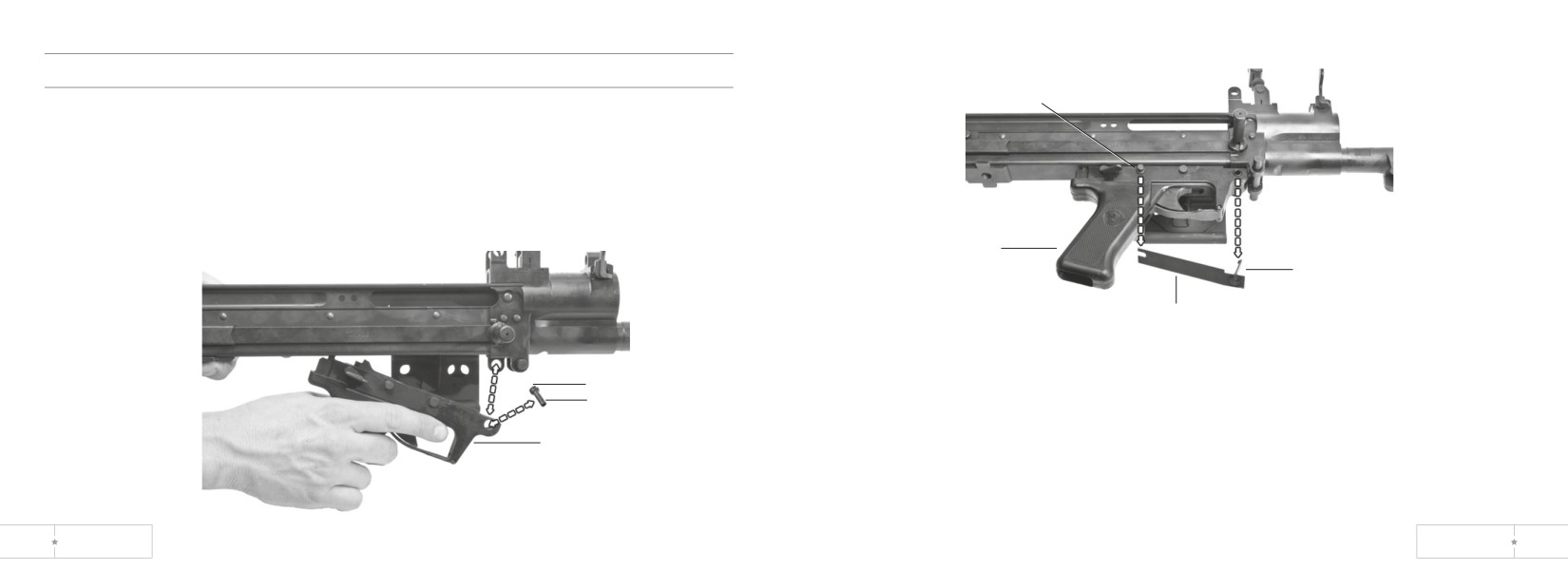
Trigger Mechanism Grip Assembly
grooved pin
1. Position trigger mechanism grip assembly in bottom slot of receiver.
2. Align holes and install front pin. Position the flat on the head of the pin parallel with
the gun receiver so it fully enters the hole.
grip
assembly
latch
assembly
flat
spring
flat head
front pin
3. Hold latch assembly with latch pointed towards the front of the grip assembly. Slide
slotted end of flat spring onto grooved pin in the grip assembly.
trigger mechanism
4. Align latch pin with the hollow front pin and push it into the pin until the hook snaps
grip assembly
into position.
5. Verify that the latch is secured.
82
US ORDNANCE
MK 43 MOD 0
83
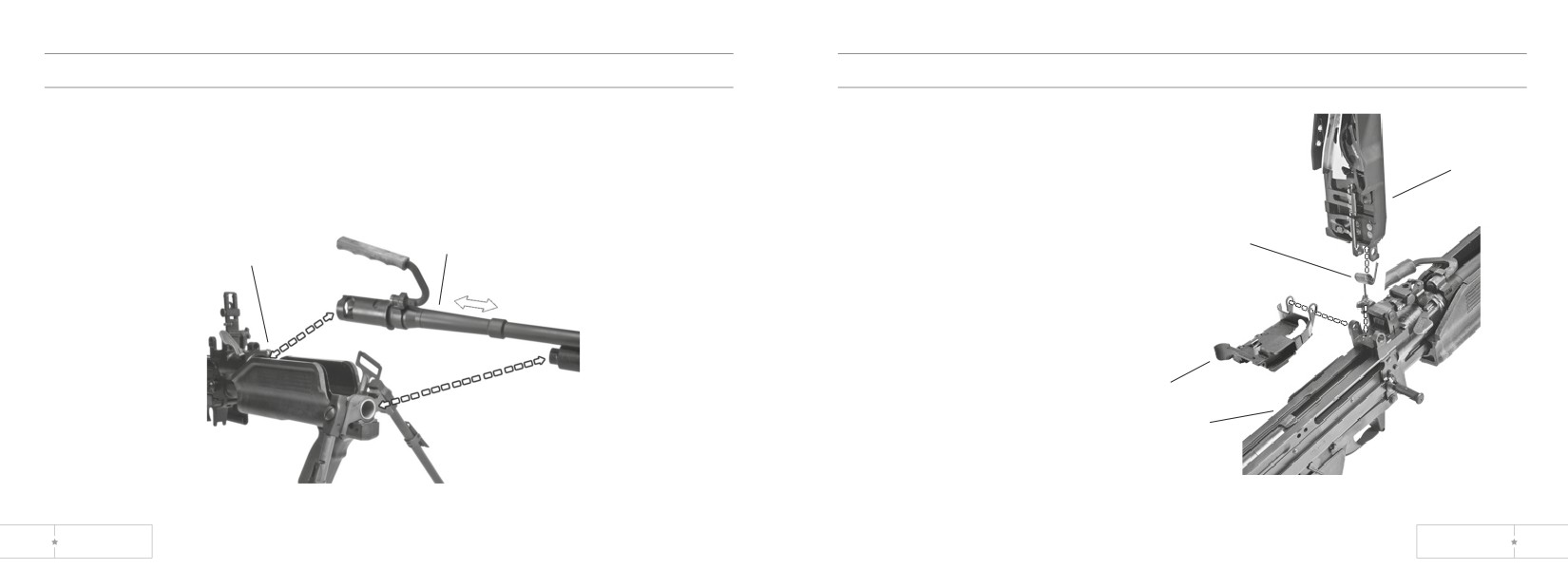
Barrel and Handle Assembly
Cover and Cartridge Feed Tray Assembly
1. Make sure barrel lock lever is up (unlocked).
1. Position cartridge feed tray
2. Install barrel and handle assembly.
assembly on receiver assembly.
3. Push barrel lock down (locked).
2. Install torsion spring in cover.
cover
Make sure that ends of torsion
spring are inserted in holes of
cover and receiver.
barrel and handle
torsion
barrel lock
assembly
spring
lever
cartridge feed tray
receiver assembly
84
US ORDNANCE
MK 43 MOD 0
85
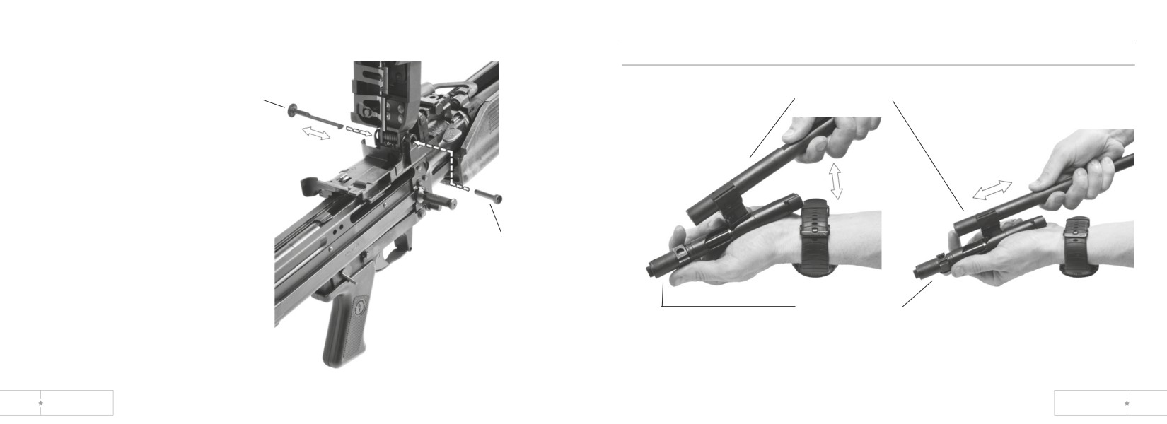
Bolt Assembly and Operating Rod Assembly
hinge pin
latch
operating rod assembly
cover
hinge pin
3. Apply slight pressure to line up
torsion .spring and insert cover
bolt assembly
hinge pin. Install hinge pin latch
through hinge pin until it locks.
1. Place tower of operating assembly against spool of firing pin in slot of bolt assembly
Keep cover assembly open until
and push spool forward.
machine gun is reassembled.
2. Seat tower between spools of firing pin. Let tower slide back in bolt assembly.
86
US ORDNANCE
MK 43 MOD 0
87
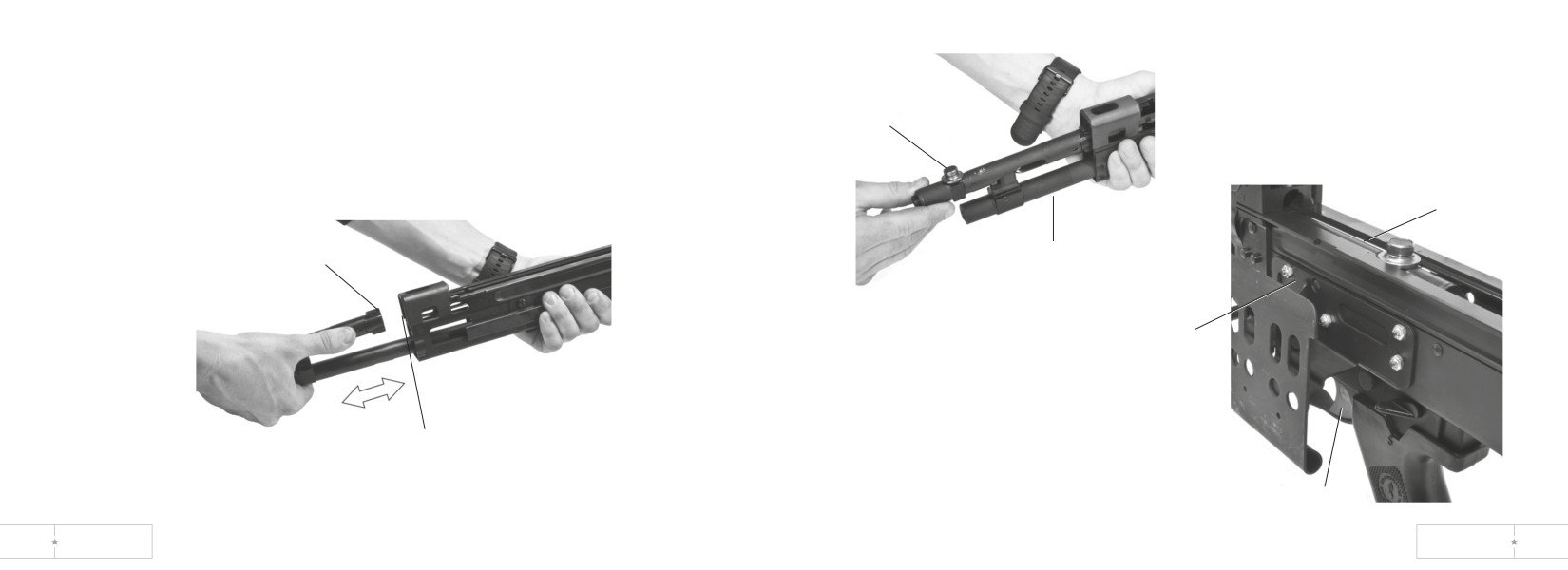
3. Start operating rod assembly with bolt assembly into weapon. Turn bolt assembly
so that stripping lugs line up with upper rails. Push in until stripping lugs engage rails.
roller
breech
bolt
stripping lugs
operating rod
assembly
receiver
receptor
4. Turn roller straight up and push bolt
assembly and operating rod assembly
rails
as a unit into weapon.
5. Move safety to F. Pull back on trigger and hold.
trigger
Push breech bolt into receiver until it locks in place.
88
US ORDNANCE
MK 43 MOD 0
89
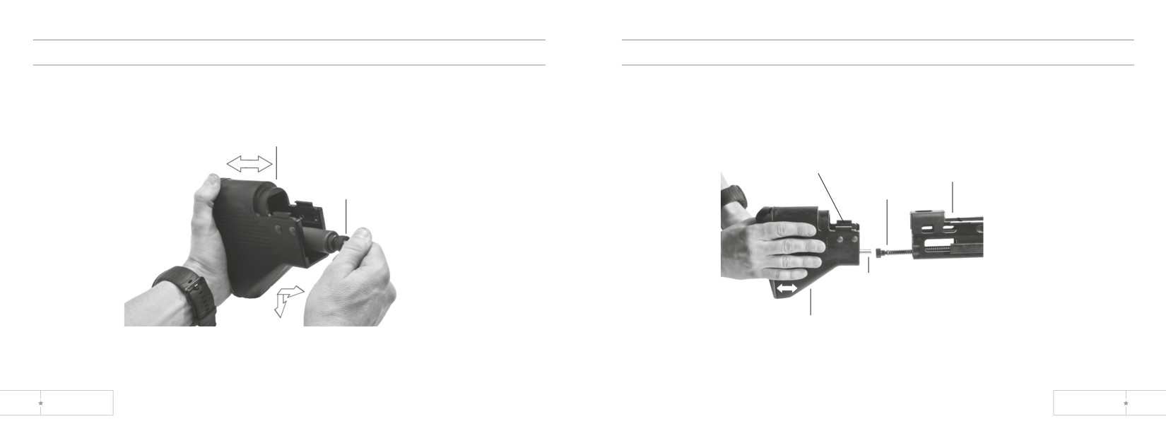
Shoulder Buttstock and Buffer Assembly
Assembly of Buttstock to Receiver
1. Install the buffer assembly into the buttstock as shown.
1. Install the drive spring and the drive spring guide into the receiver.
2. Align the drive spring guide with the buffer assembly.
3. Slide the buttstock onto the end of the receiver.
shoulder
buttstock
buffer
assembly
buffer
receiver
drive
assembly
spring
drive spring
guide
shoulder
buttstock
90
US ORDNANCE
MK 43 MOD 0
91
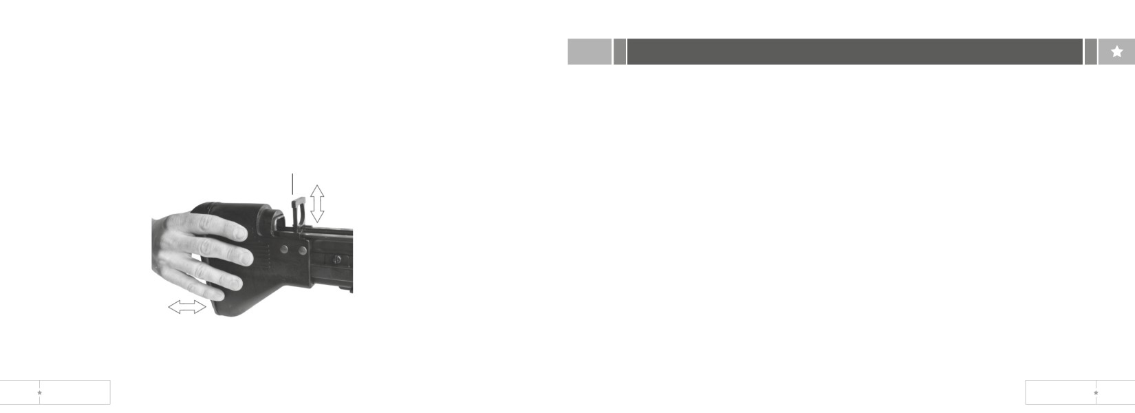
4. Push the buttstock forward as shown and install the yoke.
section VI. Maintenance Checklist
5. Close cover.
6. Manually cycle weapon system to ensure proper function.
Check the cleanliness and overall condition of the following:
1. Barrel assemblies. Chamber, bore and flash suppressor, gas cylinder, gas port, and
gas piston.
2. Receiver assembly. Operating rod guide, rails, and rear bridge rivets.
retaining
3. Bolt assembly.
yoke
4. Front and rear sights.
5. Shoulder buttstock.
6. Bipod assembly.
7. Trigger mechanism grip assembly.
8. Cocking handle assembly.
9. Cover assembly and cartridge feed tray assembly.
10. Blank firing attachment (BFA). Clean after firing 500 rounds or after each day’s
firing, whichever comes first. Remember BFA causes carbon fouling.
92
US ORDNANCE
MK 43 MOD 0
93
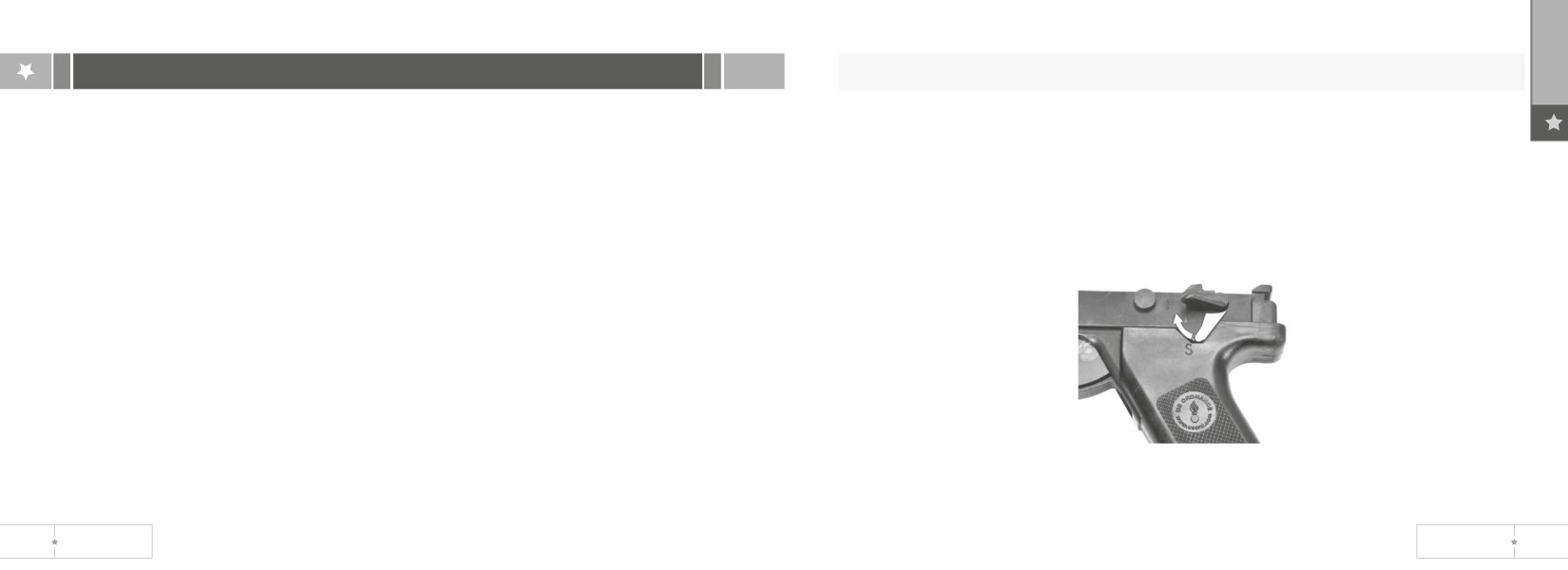
section VII. machine gun check out procedure
WARNING: After unloading dummyround, be sure the barrel is cleared.
7. Move safety to S.
Bolt Assembly Rearward? Good. Safety in S? Good.
8. Unload dummy ammunition and clear weapon (p 26).
1. Point weapon down range.
9. Verify that the projectile stayed with the dummy cartridge case.
2. Load machine gun with dummy ammunition (p 24).
10. Close cover and latch.
3. Squeeze trigger. Nothing should happen.
11. Move safety to F. Pull cocking handle, squeeze trigger and ease bolt assembly
4. Move safe to F.
forward.
5. Squeeze trigger. Bolt assembly should move forward, strip and chamber a dummy
round, and lock.
6. Pull cocking handle back. Dummy round should eject, and bolt assembly should
lock to rear.
94
US ORDNANCE
MK 43 MOD 0
95
Care, Handling, and Preservation.
chapter 4 - ammunition
a. Do not open ammunition containers until the ammunition is to be used. Ammunition
removed from the airtight containers, particularly in damp climates, is likely to corrode.
b. Protect ammunition from mud, dirt and water. If the ammunition gets wet or dirty,
wipe it off prior to use. Wipe off light corrosion as soon as it is discovered. Heavily
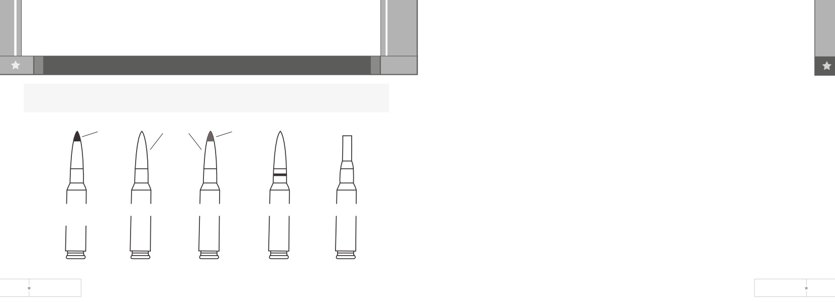
WARNING: This is the only ammunition authorized for use in your machine gun.
corroded cartridges or cartridges which have dented cases or loose projectiles should
If it is not shown, it is not authorized.
not be fired.
c. Do not expose ammunition to the direct rays of the sun. If the powder is hot,
black
4-1 combat
red or
excessive pressure may be developed when the gun is fired.
mix
orange
d. Do not oil or grease ammunition. Dust and other abrasives collecting on oiled or
greased ammunition will damage the operating parts of the gun.
Ammunition Which Fails To Fire.
Dispose of any ammunition, which fails to fire, according to authorized procedures.
armor
ball
tracer
dummy
blank
piercing
96
US ORDNANCE
MK 43 MOD 0
97
Forms
appendix a
DA Form 2028 -Recommended Changes to Publications and Blank Forms SF 368 -
Quality Deficiency Report
references
Technical Manuals.
TM 02705E-IO/l- Operators Manual for Machine Gun, 7.62 MM, M60E3 and Mount,
Tripod, Machine Gun, 7.62MM, M122.
Scope.
This appendix lists some manuals referenced in this manual, and some other sources
TM 3-220 - Chemical, Biological and Radiological (CBR) Decontamination
of information about M60 machine guns and ancillary equipment.
TM 11-5855-213-10 -Operators Manual for Night Vision Sight, Individual Served
Field Manuals.
Weapon, AN/PVS4
Machine gun 7.62-MM, M60 -- FM 23-67
Firing Table.
FT 7.62-A-2
Machine Gun, 7.62-mm; M60 on Mount, Machine Gun: 7.62-mm, Ml22 and Machine
Gun, 7.62-mm: M73 on Tank, Combat, Full-Tracked: 105-mm Gun, M60 Series and
Rifle, 7.62mm: M14; Firing Cartridge, 7.62mm, Ball, NATO, M59; Cartridge, 7.62mm,
Ball, NATO, M80; Cartridge, 7.62mm: AP, NATO, M61 and Cartridge, 7.62mm: Tracer,
NATO, M62.
98
US ORDNANCE
MK 43 MOD 0
99
Although shipped separately packaged, BII must be with the MK43 Mod0 machine
appendix b
gun during operation and whenever it is transferred between property accounts. The
illustrations will assist you with hard-to-identify items. This manual is your authority to
section I. Introduction
request/requisition replacement BII, based on approved allowance for the end item.
Explanation of Columns
Scope.
The following provides an explanation of columns found in the tabular listings:
This appendix lists components of end item and basic issue items for the MK43 MOD
a. Column (I) - Illustration Number. This column indicates the number of the illustration
0 machine gun to help you inventory items required for safe and efficient operation.
in which the item is shown.
General.
b. Column (2) - National Stock Number. Indicates the National stock number assigned
The Components of End Item and Basic Issue Items Lists are divided into the
to the item and will be used for requisitioning purposes.
following sections:
c. Column (3) - Description. Indicates the Federal item name and, if required, a
a. Section II. Components of End Item. This listing is for informational purposes only
minimum description to identify and locate the item. The last line for each item
and is not authority to requisition replacements. These items are part of the end
indicates the Contractor and Government Entity Code (CAGEC) (in parentheses)
item but are removed and separately packaged for transportation or shipment. As
followed by the part number.
part of the end item, these items must be with the end item whenever it is issued
d. Column (4) - Unit of Measure (U/M). Indicates the measure used in performing
or transferred between property accounts. Illustrations are furnished to assist you
the actual operational/maintenance function. This measure is expressed by a two-
identifying the items.
character alphabetical abbreviation (e.e., ea., in., pr.).
b. Section III. Basic Issue Items. These are the minimum essential items required
e. Column (5) - Quantity required. Indicates the quantity of the item authorized to be
to place the MK43MOD0 machine gun in operation, to operate it, and to perform
used with/on the equipment.
emergency repairs.
100
US ORDNANCE
MK 43 MOD 0
101
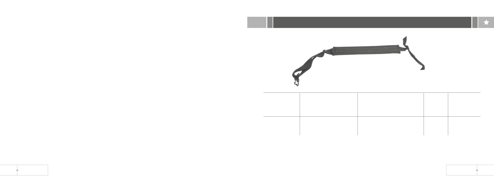
section II. Components of End item
This page intentionally left blank
(1)
(2)
(3)
(4)
(5)
Illustration
National
Description
U/M
Quantity
Number
Stock Number
CAGEC & Part Number
Required
1
1005-00-312-7177
Sling, Small Arm
EA
1
(19204) 12002983
102
US ORDNANCE
MK 43 MOD 0
103
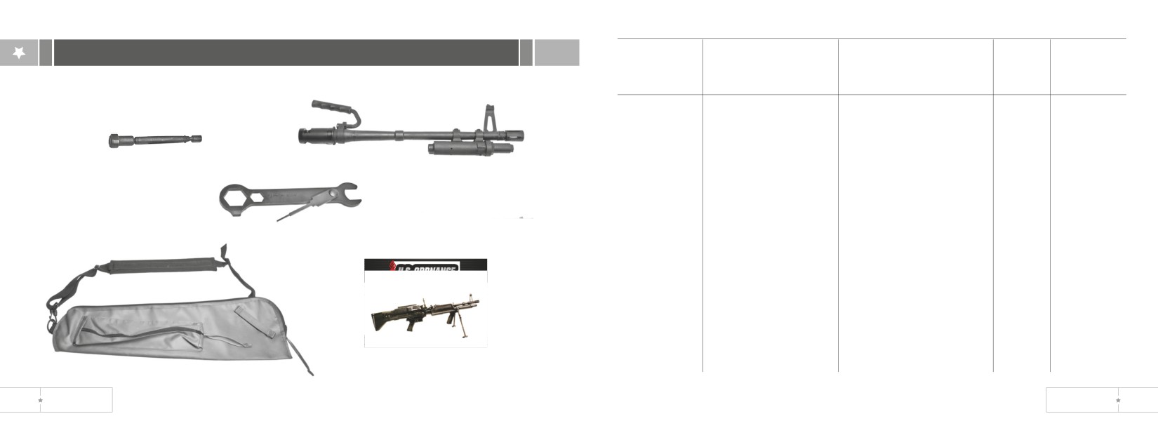
section III. basic issue items
(1)
(2)
(3)
(4)
(5)
Illustration
National
Description
U/M
Quantity
Number
Stock Number
CAGEC & Part Number
Required
3
1
1
1005-01-184-6362
Barrel and carrying
EA
1
handle assembly (26978)
MD3521
4
2
1005-01-791-5420
Carrying case for barrel
EA
1
assembly and equipment
(19205) 7791009
3
4933-00-652-9950
Extractor for ruptured
EA
1
cartridge case (19205)
2
5
7790352
4
5120-00-461-1075
Wrench, screwdriver, and
EA
1
reamer (combination)
(19204) 8448458
5
0640-LP-544-4800
TM, Operators Manual
EA
1
SW-370-AJ-OPII-010/
M43 MOD 0
104
US ORDNANCE
MK 43 MOD 0
105
(1)
(2)
(3)
(4)
(5)
Illustration
National
Description
U/M
Quantity
6
8
Number
Stock Number
CAGEC & Part Number
Required
6
5340-01-285-2683
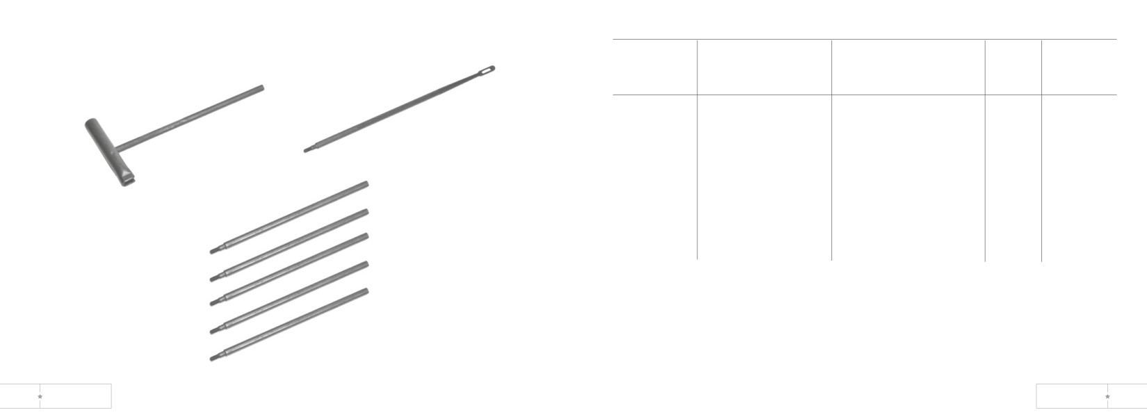
Handle assembly:
EA
1
Cleaning rod (19204)
7266115
7
1005-00-726-6109
Rod sections, cleaning,
EA
5
small arms (19204)
7
7266109
8
1005-00-726-6110
Swab holder section,
EA
1
small arms cleaning rod
(19204) 7266110
106
US ORDNANCE
MK 43 MOD 0
107
section II. additional authorized list
appendix c - additional authorized list
section I. Introduction
(1)
(2)
(3)
(4)
National
Description
U/M
Quantity
Stock Number
FSCM & Part Number
Required
Scope.
The appendix lists additional items you are authorized for the support of the MK43
1005-00-140-3515
Firing attachment, blank:
EA
1
MOD0 Machine Gun.
(19204) 12002981
1005-00-556-4174
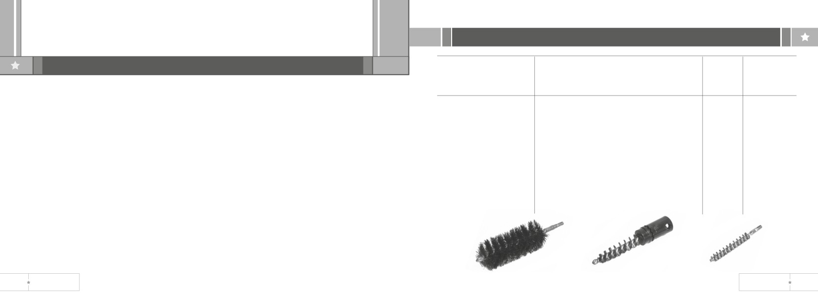
Brush, cleaning, small arms:
EA
2
General.
(bore) (19204) 5564174
This list identifies items that do not have to accompany the MK43 MOD 0 Machine
Gun and that do not have to be turned in with it.
1005-00-690-3115
Brush, cleaning, small arms:
EA
1
(chamber) (19204) 7790452
Explanation of Listing.
National stock numbers, descriptions, and quantities are provided to help you identify
1005-00-350-4100
Brush, cleaning, small arms:
EA
1
and request the additional items you require to support this equipment.
(receiver) (19204) 8448466
Bore
chamber
receiver
Brush
brush
brush
108
US ORDNANCE
MK 43 MOD 0
109
c. Column (3) - National Stock Number. This is the National stock number
appendix d - expendable supplies
assigned to the item; use to request or requisition the item.
d. Column (4) - Description. Indicates the Federal item name and, if required, a
section I. Introduction
description to identify item. The last line for each item indicates the Contractor and
Government Entity Code (CAGEC) in parentheses followed by the part number.
e. Column (5) - Unit of Measure (U/M). Indicates the measure used in performing
Scope.
the actual maintenance function. This measure is expressed by a two-character
This appendix lists expandable su plies and materials you will need to operate and
alphabetical abbreviation (e.g., ea., in., pr.). If the unit of measure differs from the
maintain the MK43 M 8 D 0 Machine Gun.
unit of issue, requisition the lowest unit of issue that will satisfy your requirements.
Explanation of Columns.
a. Column (1) - Item Number (Item Number). This number is assigned to the entry in
the listing and is referenced in the narrative instructions to identify the material
(e.g., “Use wiping rag, item 4, app D).
b. Column (2) - Level. This column identifies the lowest level of maintenance that
requires the listed item.
110
US ORDNANCE
MK 43 MOD 0
111
section II. expendable/durable supplies and materials list
(1)
(2)
(3)
(4)
(5)
Item
Level
National Stock
Description
U/M
Number
Number
CAGEC & Part Number
1
C
9150-01-102-1473
Cleaner, lubricant and
OZ
preservative (CLP) 1/2 oz.
bottle (81349) MIL-L-63460
2
C
9150-00-753-4686
Lubricating Oil (LSA)
QT
3
C
9150-00-292-9689
Lubricating Oil (LAW)
QT
4
C
7920-00-205-1711
RAG WIPING: (cotton) 50lb.
LB
bdl. (81348) a-a-531
5
C
1005-00-288-3565
Swab, small arms cleaning
PG
(cotton) 2 1/2 in. sq. (1000
per pkg.) (19204) 5019316
112
US ORDNANCE