ZEB, Lyrik, Pike. Service manual (2023)

TABLE OF CONTENTS
ROCKSHOX SERVICE
5
PART PREPARATION
5
SERVICE PROCEDURES
5
MODEL CODE IDENTIFICATION
6
WARRANTY AND TRADEMARK
6
PARTS, TOOLS, AND SUPPLIES
7
RECOMMENDED SERVICE INTERVALS
8
RECORD YOUR SETTINGS
8
TORQUE VALUES
9
OIL VOLUME AND LUBRICANT
10
EXPLODED VIEW
11
2023+ (A2) ZEB ULTIMATE - CHARGER 3 RC2 - DEBONAIR+
11
2023+ (A2) ZEB ULTIMATE - CHARGER 3 RC2 - DUAL POSITION AIR
12
2023+ (A2) ZEB SELECT+ - CHARGER 3 RC2 - DEBONAIR+
13
2023+ (A2) ZEB SELECT+ - CHARGER 3 RC2 - DUAL POSITION AIR
14
2023+ (A2) ZEB SELECT - CHARGER RC - DEBONAIR+
15
2023+ (A2) ZEB SELECT - CHARGER RC - DUAL POSITION AIR
16
2023+ (A2) ZEB BASE - RUSH RC - DEBONAIR+
17
2023+ (A2) ZEB BASE - RUSH RC - DUAL POSITION AIR
18
2023+ (D1) LYRIK ULTIMATE - CHARGER 3 RC2 - DEBONAIR+
19
2023+ (D1) LYRIK SELECT+ - CHARGER 3 RC2 - DEBONAIR+
20
2023+ (D1) LYRIK SELECT - CHARGER RC - DEBONAIR+
21
2023+ (D1) LYRIK BASE - RUSH RC - DEBONAIR+
22
2023+ (C1) PIKE ULTIMATE - CHARGER 3 RC2 - DEBONAIR+
23
2023+ (C1) PIKE SELECT+ - CHARGER 3 RC2 - DEBONAIR+
24
2023+ (C1) PIKE SELECT - CHARGER RC - DEBONAIR+
25
2023+ (C1) PIKE BASE - RUSH RC - DEBONAIR+
26
LOWER LEG FEATURES - ZEB, LYRIK, PIKE
27
BUTTERCUPS - ZEB, LYRIK, PIKE - ULTIMATE - CHARGER 3 RC2 AND DEBONAIR+
28
OPTIONAL UPGRADE - PRESSURE RELIEF VALVE (PRV) INSTALLATION - SELECT, BASE
29
LOWER LEG REMOVAL AND SERVICE
30
50/200 HOUR SERVICE
LOWER LEG REMOVAL
30
50 HOUR SERVICE
LOWER LEG SERVICE
34
200 HOUR SERVICE
LOWER LEG SEAL SERVICE
36
DEBONAIR+ - AIR SPRING SERVICE, TRAVEL CHANGE, AND BUTTERCUPS UPGRADE
39
200 HOUR SERVICE
AIR SPRING REMOVAL
39
BUTTERCUPS REMOVAL - DEBONAIR+ - ULTIMATE
44
DEBONAIR+ AIR SPRING TRAVEL CHANGE (OPTIONAL)
46
DEBONAIR+ BOTTOMLESS TOKENS
50
DEBONAIR+ BOTTOMLESS TOKENS INSTALLATION (OPTIONAL)
50
AIR SPRING SERVICE
51
BUTTERCUPS INSTALLATION - DEBONAIR+ - ULTIMATE
56
AIR SPRING INSTALLATION
59
DUAL POSITION AIR (DPA) - ZEB - AIR SPRING SERVICE
64
200 HOUR SERVICE
AIR SPRING REMOVAL
64
DPA AIR SPRING TRAVEL AND BOTTOMLESS TOKENS
67
DPA BOTTOMLESS TOKENS INSTALLATION (OPTIONAL)
67
DPA AIR SPRING TRAVEL CHANGE AND BOTTOMLESS TOKENS (OPTIONAL)
68
AIR SPRING SERVICE
68
AIR SPRING INSTALLATION
70

DAMPER SERVICE - CHARGER 3 RC2
74
200 HOUR SERVICE
CONTROLS REMOVAL - CHARGER 3 RC2
74
DAMPER REMOVAL - CHARGER 3 RC2
76
BUTTERCUPS REMOVAL - CHARGER 3 RC2 - ULTIMATE
77
DAMPER SERVICE - CHARGER 3 RC2
79
DAMPER ASSEMBLY - CHARGER 3 RC2
87
BUTTERCUPS INSTALLATION - CHARGER 3 RC2 - ULTIMATE
97
DAMPER BLEED - CHARGER 3 RC2
100
TEST COMPRESSION - CHARGER 3 RC2
104
DAMPER INSTALLATION - CHARGER 3 RC2
105
CONTROLS INSTALLATION - CHARGER 3 RC2
107
DAMPER SERVICE - CHARGER RC
110
200 HOUR SERVICE
CONTROLS REMOVAL - CHARGER RC
110
DAMPER REMOVAL - CHARGER RC
111
DAMPER SERVICE - CHARGER RC
112
DAMPER ASSEMBLY - CHARGER RC
116
TEST COMPRESSION - CHARGER RC
121
DAMPER INSTALLATION - CHARGER RC
122
CONTROLS INSTALLATION - CHARGER RC
124
DAMPER SERVICE - RUSH RC
125
200 HOUR SERVICE
CONTROLS REMOVAL - RUSH RC
125
DAMPER REMOVAL - RUSH RC
126
DAMPER SERVICE - RUSH RC
127
DAMPER ASSEMBLY - RUSH RC
130
TEST COMPRESSION - RUSH RC
134
DAMPER INSTALLATION - RUSH RC
135
CONTROLS INSTALLATION - RUSH RC
137
LOWER LEG ASSEMBLY
138
50/200 HOUR SERVICE
LOWER LEG INSTALLATION
138
RockShox Service
We recommend that you have your RockShox suspension serviced by a qualified bicycle mechanic. Servicing RockShox suspension requires
knowledge of suspension components, as well as the use of specialized tools and lubricants/fluids. Failure to follow the procedures outlined in this
service manual may cause damage to your component and void the warranty.
Visit www.sram.com/service for the latest RockShox Spare Parts Catalog and technical information. For order information, please contact your local
SRAM distributor or dealer.
Information contained in this publication is subject to change at any time without prior notice.
Your product's appearance may differ from the pictures contained in this publication.
For recycling and environmental compliance information, please visit: www.sram.com/en/company/about/environmental-policy-and-recycling.
Part Preparation
Remove the component from the bicycle before service.
Disconnect and remove the remote cable or hydraulic hose from the fork or rear shock, if applicable. For additional information about RockShox
remotes, user manuals are available at www.sram.com.
Clean the exterior of the product with mild soap and water to avoid contamination of internal sealing part surfaces.
Service Procedures
The following procedures should be performed throughout service, unless otherwise specified.
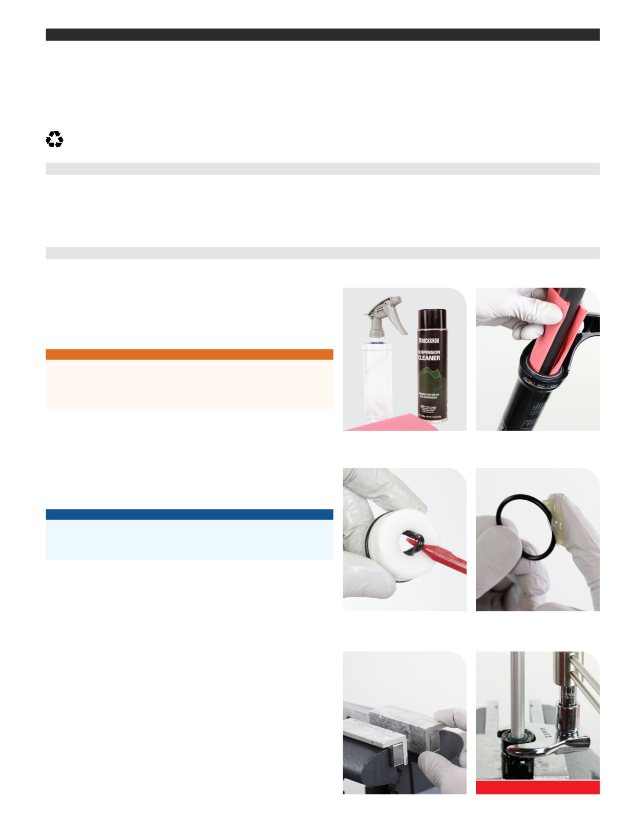
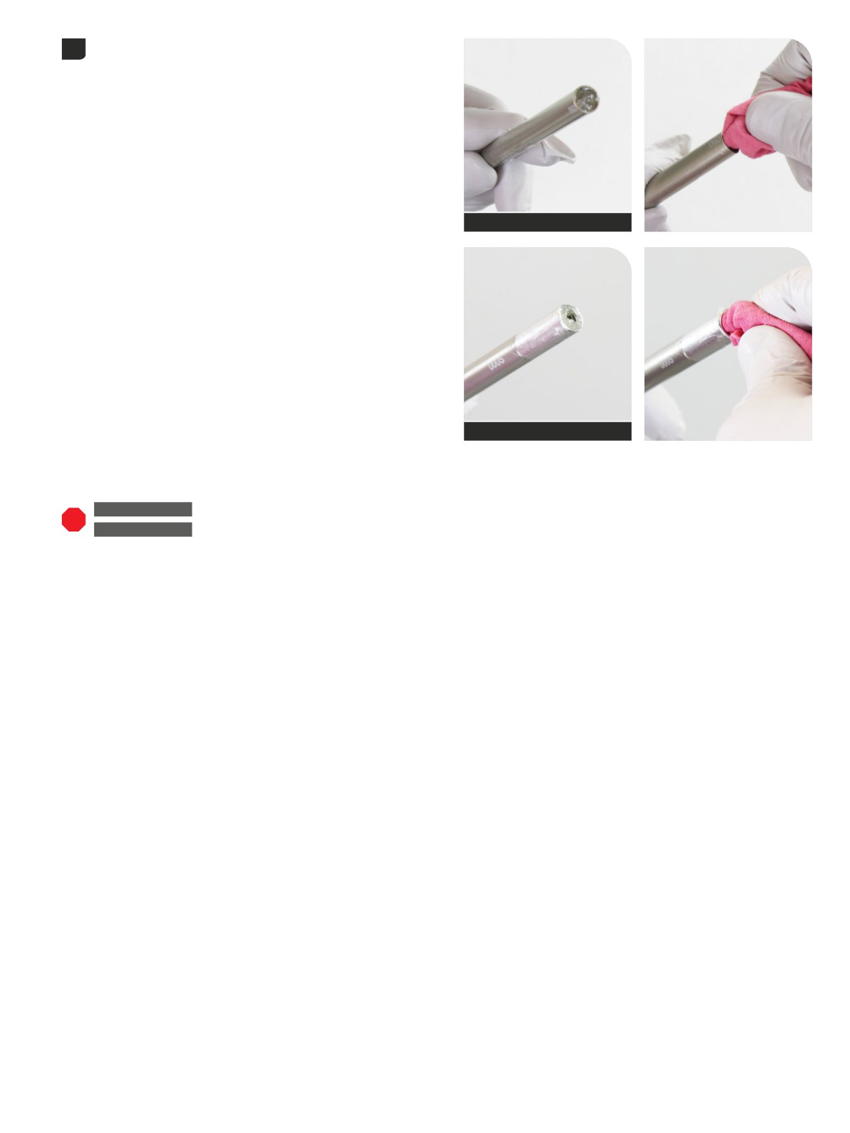
Clean the part with RockShox Suspension Cleaner or isopropyl alcohol and
a clean, lint-free shop towel. For hard to reach places (e.g. upper tube, lower
leg), wrap a clean, lint-free shop towel around a non-metallic dowel to clean
the inside.
Clean the sealing surface on the part and inspect it for scratches.
⚠WARNING - CRASH HAZARD
DO NOT use vinegar of any type to clean any part of a RockShox
suspension product. Vinegar can cause permanent damage to parts which
can, over time, result in product structural failure, serious injury, and possibly
death.
Replace the o-ring or seal with a new one from the service kit. Use your
fingers or a pick to pierce and remove the old seal or o-ring.
Apply grease to the new seal or o-ring.
NOTICE
Do not scratch any sealing surfaces when servicing the product. Scratches
can cause leaks. Consult the spare parts catalog to replace the damaged
part.
Use aluminum soft jaws when placing a part in a bench vise.
Tighten the part with a torque wrench to the torque value listed in the red bar.
When using a crowfoot socket and torque wrench, install the crowfoot socket
at 90 degrees to the torque wrench.
Specified torque value in N·m (in-lb)
RockShox Service
5

Model Code Identification
Product model code and specification details can be identified with the serial number on the product. Model codes can be used to identify the
product type, series name, model name, and product version associated with the production model year. Product details can be used to identify spare
parts, service kit, and lubricant compatibility.
Model Code example: FS-LYRK-ULT-D1
FS = Product Type - Front Shock/Suspension
LYRK = Platform/Series - Lyrik
ULT = Model - Ultimate
D1 = Version - (D - fourth generation, 1 - first iteration)
To identify the model code, locate the serial number on the product and enter it into the Search by Model Name or Serial Number field at
www.sram.com/service.
Warranty and Trademark
For SRAM Warranty information, visit: www.sram.com/warranty.
For SRAM Trademark information, visit: www.sram.com/website-terms-of-use.
Model Code Identification
6

Parts, Tools, and Supplies
Parts
Bicycle Tools
•
2023+ (A2) ZEB - 200 Hour Service Kit
• Bicycle work stand
•
2023+ (D1) Lyrik - 200 Hour Service Kit
• Downhill tire lever
•
2023+ (C1) Pike - 200 Hour Service Kit
• Shock pump
• DebonAir+ Air Spring Shaft assembly (optional travel change)
Common Tools
• DebonAir+ Upgrade Kit : Air Spring assembly with ButterCups
•
Adjustable wrench or open end wench: 19, 23, 25, 28 mm
• Charger 3 RC2 Ultimate Upgrade Kit : Damper assembly with
•
Bench vise with aluminum soft jaw inserts
ButterCups
•
Crowfoot: 19, 23, 25, 28 mm
Safety and Protection Supplies
•
Hex bit sockets: 1.5, 2, 2.5, 5 mm
• Apron
•
Hex wrenches: 1.5, 2, 2.5, 4, 5, 8 mm
• Clean, lint-free shop towels
•
Internal retaining ring pliers (large) - air spring retaining ring (ZEB)
• Nitrile gloves
•
Long plastic or wooden dowel
• Oil pan
•
Pick (metallic) - air spring retaining ring (Lyrik/Pike)
• Safety glasses
•
Pick (non-metallic) - for all o-rings and seals
Lubricants and Fluids
•
Plastic mallet
• Maxima PLUSH 3wt Suspension Oil (Charger RC, Rush RC)
•
Plastic tube (split conduit loom) or similar - air spring and damper shaft
• Maxima PLUSH 7wt Suspension Oil (Charger 3 RC2)
protective cover
• Maxima PLUSH Dynamic Suspension Lube Heavy (air spring)
•
Socket: 10, 24, mm
• Maxima PLUSH Dynamic Suspension Lube Light (lower legs)
•
Socket wrench
• RockShox Dynamic Seal Grease (PRV o-ring only)
•
Torque wrench
• RockShox Suspension Cleaner or isopropyl alcohol
•
TORX bit socket: T25
• SRAM Butter Grease
•
TORX wrench: T25
RockShox Tools
• RockShox Bleed Syringe
• RockShox Dust Seal Installation Tool (38 mm) or RockShox x Abbey
Bike Tools 38 mm Flangeless Dust Seal Installation Tool
• RockShox Dust Seal Installation Tool (35 mm) or RockShox x Abbey
Bike Tools 35 mm Flangeless Dust Seal Installation Tool
• RockShox Reverb Vise Blocks (Charger 3 RC2, Rush RC)
• Charger Vise Blocks (Charger RC)
• RockShox Shock Pump
• RockShox Top Cap/Cassette Tool (3/8" / 24 mm) or RockShox x
Abbey Bike Tools Top Cap/Cassette Tool
SAFETY INSTRUCTIONS
Always wear safety glasses and nitrile gloves when working with suspension oil.
Place an oil pan on the floor underneath the area where you will be working on the shock or suspension fork.
Parts, Tools, and Supplies
7

Recommended Service Intervals
Regular service is required to keep your RockShox product working at peak performance. Follow this maintenance schedule and install the service
parts included in each service kit that corresponds with the Service Hours Interval recommendation below. For spare part kit contents and details,
refer to the RockShox Spare Parts Catalog at www.sram.com/service.
Service Hours Interval
Maintenance
Benefit
Extends wiper seal lifespan
Every ride
Clean dirt from upper tubes and wiper seals
Minimizes damage to upper tubes
Minimizes lower leg contamination
Restores small bump sensitivity
Every 50 hours
Perform lower leg service
Reduces friction
Extends bushing lifespan
Extends suspension lifespan
Every 200 hours
Perform damper and spring service
Restores small bump sensitivity
Restores damping performance
Record Your Settings
Use the table below to record your suspension settings to return your suspension to its pre-service settings. Record your service dates to track
service intervals.
Rebound setting -
LSC setting - Count
HSC (RC2) setting -
Count the number of
the number of clicks
Count the number of
clicks while turning
Service Hours Interval
Date of Service
Air Pressure
while turning the LSC
clicks while turning
the rebound adjuster
adjuster fully
the HSC adjuster fully
fully counterclock-
counterclockwise.
counterclockwise.
wise.
50
100
150
200
Recommended Service Intervals
8

Torque Values
Part
Tool
Torque
Air spring shaft insert (Select+, Select, Base - DebonAir+ only)
5 mm hex bit socket
4 N•m (32 in-lb)
Bottom bolt - air spring and damper
5 mm hex bit socket
6.8 N•m (60 in-lb)
Bottomless Token
8 mm hex bit socket
4 N•m (35 in-lb)
ButterCups housing shaft end plate - end plate to shaft - Air Spring
TORX T25 bit socket
4 N•m (32 in-lb)
ButterCups housing (upper) to ButterCups housing (lower) - Air Spring
25 mm crow foot
14 N•m (125 in-lb)
ButterCups housing shaft end plate - end plate to shaft - Damper
TORX T25 bit socket
5 N•m (45 in-lb)
ButterCups housing (upper) to ButterCups housing (lower) - Damper
25 mm crow foot
14 N•m (125 in-lb)
Cam set screw - compression damper adjuster (HSC) x2
1.5 mm hex bit socket
0.56 N•m (5 in-lb)
Piston nut - compression damper -
3 mm hex bit socket
1.13 N•m (10 in-lb)
Charger 3 RC2 (Ultimate, Select+)
Pressure Relief Valve (PRV) and Plug
10 mm socket
2 N•m (17 in-lb)
Retaining screw - compression adjuster knob -
2.5 mm hex bit socket
1.35 N•m (12 in-lb)
Charger RC (Select)
Retaining screw - compression adjuster knob -
2.5 mm hex bit socket
0.75 - 1.10 N•m (6.6 - 9.7 in-lb)
Rush RC (Base)
Retaining screw - low speed compression adjuster knob -
2.5 mm hex bit socket
0.56 N•m (5 in-lb)
Charger 3 RC2 (Ultimate, Select+)
Sealhead (rebound) to damper cartridge tube to damper top cap -
23 mm crowfoot
14 N•m (125 in-lb)
Charger 3 RC2 (Ultimate, Select+)
Sealhead (rebound) to damper cartridge tube to damper top cap -
19 mm crow foot
9 N•m (80 in-lb)
Charger RC (Select), Rush RC (Base)
Set screw - high speed compression adjuster knob -
2.5 mm hex bit socket
0.28 N•m (2.5 in-lb)
Charger 3 RC2 (Ultimate, Select+)
Set screw - rebound adjuster knob
2.5 mm hex bit socket
0.84 N•m (7.5 in-lb)
Top cap - compression damper
RockShox Top Cap/Cassette Tool
(or standard cassette tool)
T
op cap - DebonAir+ spring
28 N•m (250 in-lb)
Top cap - Dual Position Air spring
24 mm socket
Torque Values
9
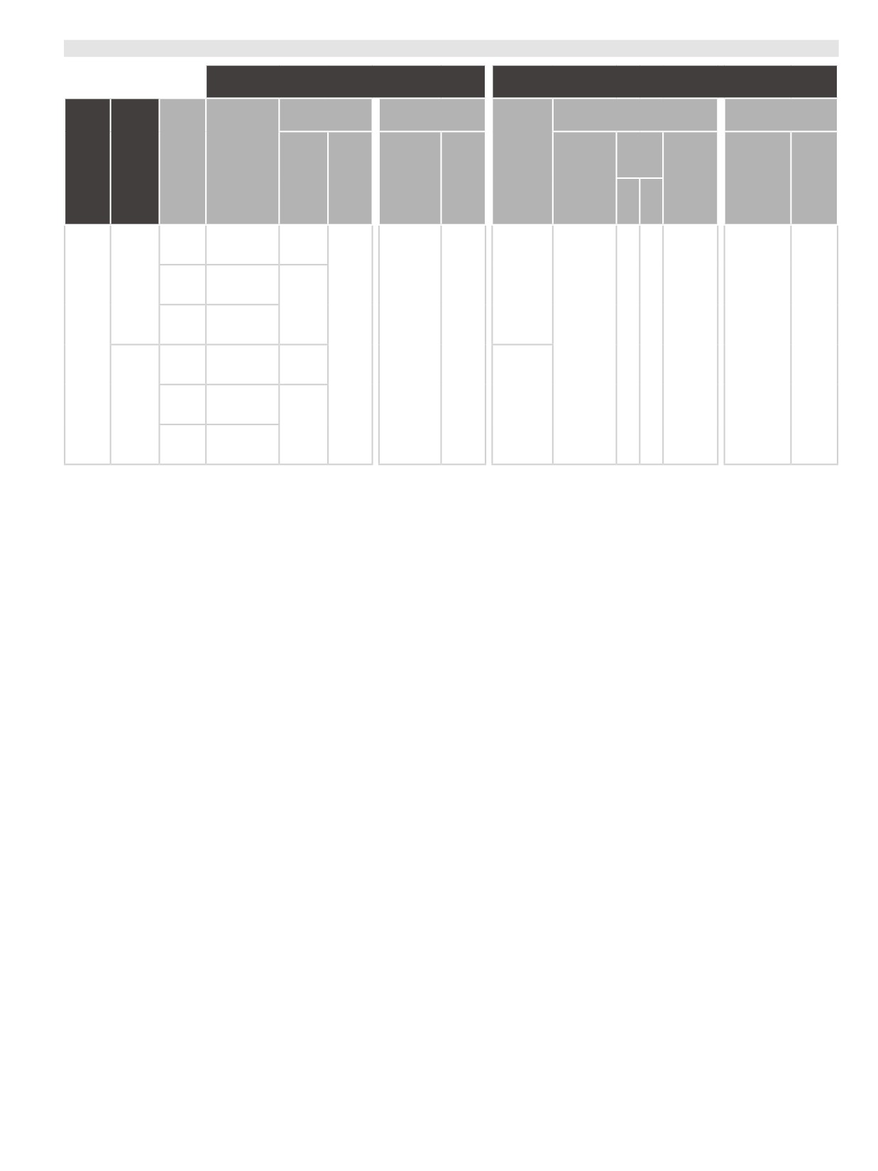
Oil Volume and Lubricant
Damper
Spring
Upper Tube
Lower Leg
Upper Tube
Lower Leg
Volume
Model
Fork
Model
Damper
Spring
(mL)
Year
Oil
Volume
Volume
Volume
Oil
Oil
Grease
Oil
Weight
(mL)
(mL)
(mL)
(+)
(−)
Ultimate
Maxima
Charger 3 RC2
PLUSH
Select+
7wt
DebonAir+
ZEB (A2)
Select
Charger RC
Dual
Maxima
Position Air
PLUSH
3wt
Base
Rush RC
Maxima
Maxima
SRAM
Maxima
PLUSH
PLUSH
Butter
PLUSH
Dynamic
Dynamic
Grease
Dynamic
2023+
Bleed
30
3
1
15
Suspension
Suspension
Suspension
Ultimate
Maxima
Lube
Lube
Grease air
Lube
Charger 3 RC2
PLUSH
Light
Heavy
piston
Light
Select+
7wt
Lyrik (D1)
Select
Charger RC
DebonAir+
Pike (C1)
Maxima
PLUSH
3wt
Base
Rush RC
Use ONLY RockShox, SRAM, and Maxima suspension oils/fluids and grease, unless otherwise specified. Use of any other lubricants can damage
seals and decrease performance.
Oil Volume and Lubricant
10
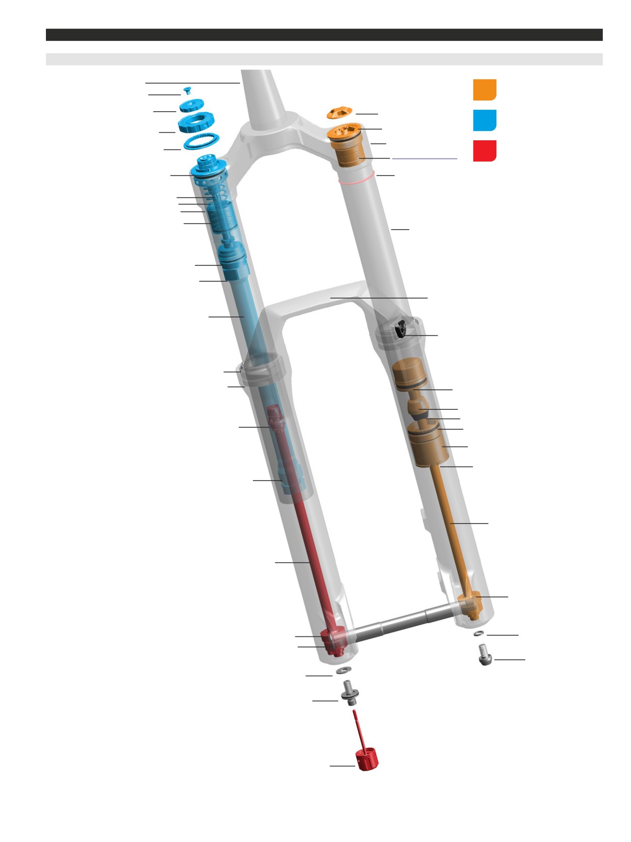
Exploded View
2023+
(A2) ZEB Ultimate
-
Charger
3
RC
2
- DebonAir+
Steerer tube
Air Spring Assembly
Retaining screw
Low speed compression (LSC)
adjuster knob
Air cap
Compression Damper
Assembly
High speed compression (HSC)
Air spring top cap
adjuster knob
Crown
Rebound Damper
Detent plate
Bottomless Token(s)
Assembly
35 mm grey (optional)
Compression damper top cap
Sag o-ring
Bleed port
IFP spring
IFP tube
Internal floating piston (IFP)
Upper tube
Compression damper
IFP tube coupler
Lower leg arch
Damper tube
Brake hose guide
Dust wiper seal
Foam ring
Air spring piston
Top out cup
Top out bumper
Rebound damper piston
Air spring sealhead
Air sealhead spacer
Retaining ring
Rebound damper sealhead
Air spring shaft
Rebound damper shaft
ButterCups (air shaft)
ButterCups (damper shaft)
Crush washer
Maxle Stealth
Air spring bottom bolt
Crush washer
Rebound bottom bolt
Rebound adjuster knob
Exploded View
11
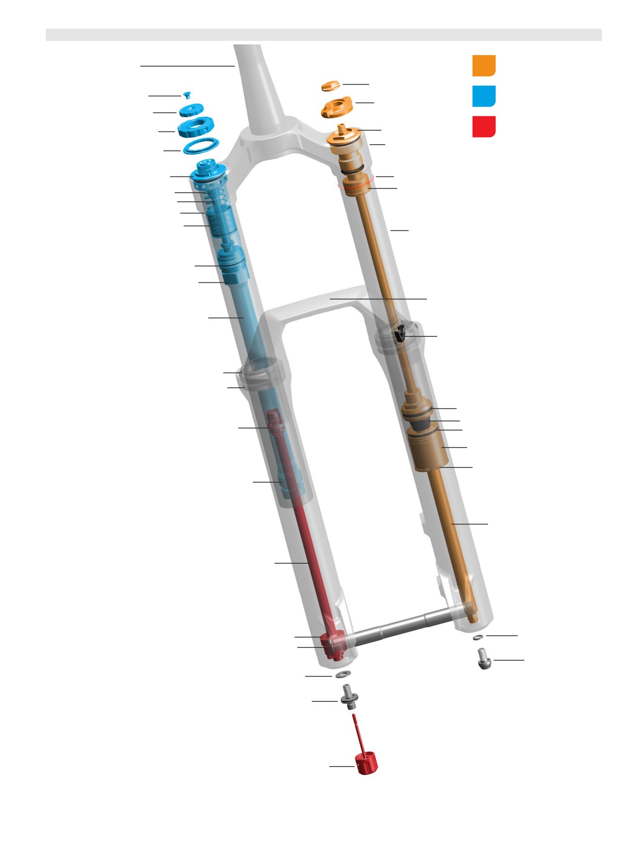
2023+
(A2) ZEB Ultimate
-
Charger
3
RC
2
- Dual Position Air
Air Spring Assembly
Steerer tube
Air cap
Compression Damper
Retaining screw
Assembly
Travel adjuster knob
Low speed compression (LSC)
adjuster knob
Rebound Damper
High speed compression (HSC)
Air spring top cap
Assembly
adjuster knob
Crown
Detent plate
Compression damper top cap
Sag o-ring
Bottomless Token(s) red (optional)
IFP spring
Bleed port
IFP tube
Internal floating piston (IFP)
Upper tube
Compression damper
IFP tube coupler
Lower leg arch
Damper tube
Brake hose guide
Dust wiper seal
Foam ring
Air spring piston
Top out bumper
Rebound damper piston
Air spring sealhead
Air sealhead spacer
Retaining ring
Rebound damper sealhead
Air spring shaft
Rebound damper shaft
ButterCups (damper shaft)
Crush washer
Maxle Stealth
Air spring bottom bolt
Crush washer
Rebound bottom bolt
Rebound adjuster knob
2023+ (A2) ZEB Ultimate - Charger 3 RC2 - Dual Position Air
12
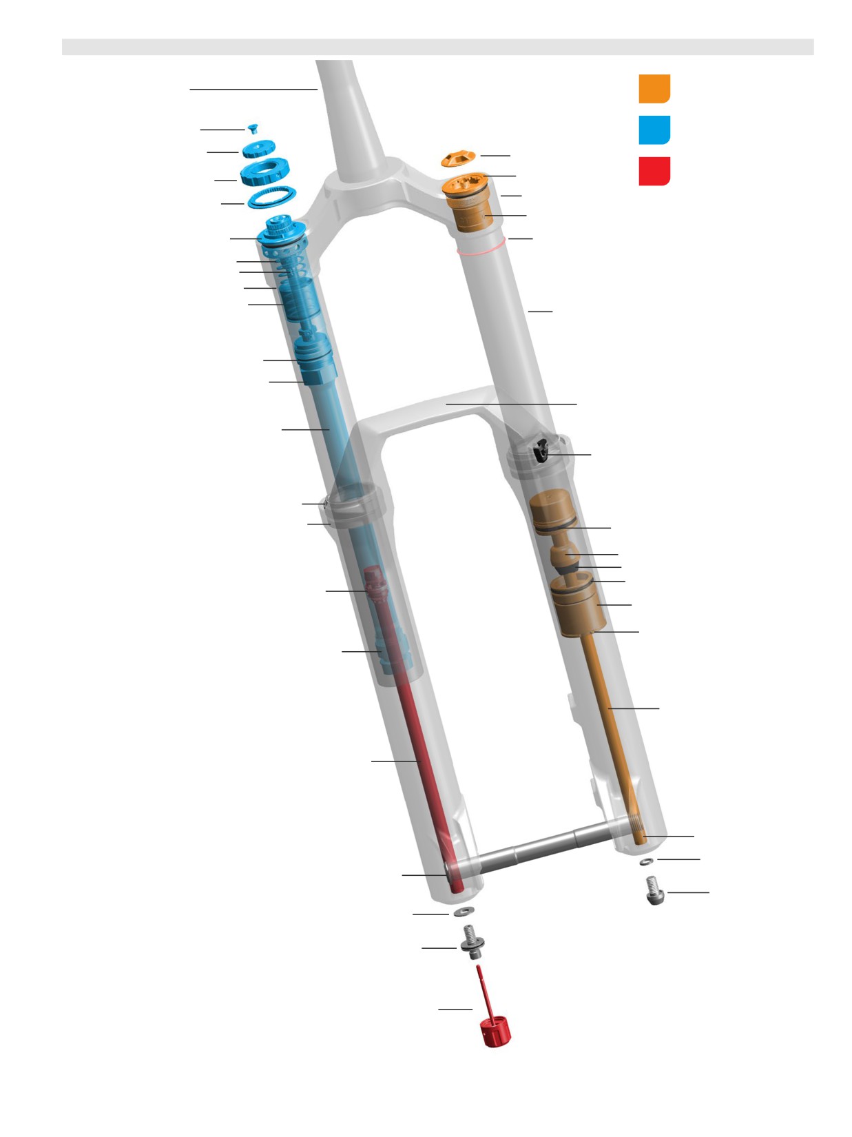
2023+
(A2) ZEB Select+
-
Charger
3
RC
2
- DebonAir+
Air Spring Assembly
Steerer tube
Compression Damper
Retaining screw
Assembly
Low speed compression (LSC)
adjuster knob
Air cap
Rebound Damper
High speed compression (HSC)
Air spring top cap
Assembly
adjuster knob
Crown
Detent plate
Bottomless Token(s) 35 mm grey (optional)
Compression damper top cap
Sag o-ring
IFP spring
Bleed port
IFP tube
Internal floating piston (IFP)
Upper tube
Compression damper
IFP tube coupler
Lower leg arch
Damper tube
Brake hose guide
Dust wiper seal
Foam ring
Air spring piston
Top out cup
Top out bumper
Air spring sealhead
Rebound damper piston
Air sealhead spacer
Retaining ring
Rebound damper sealhead
Air spring shaft
Rebound damper shaft
Air spring shaft insert
Crush washer
Maxle Stealth
Air spring bottom bolt
Crush washer
Rebound bottom bolt
Rebound adjuster knob
2023+ (A2) ZEB Select+ - Charger 3 RC2 - DebonAir+
13
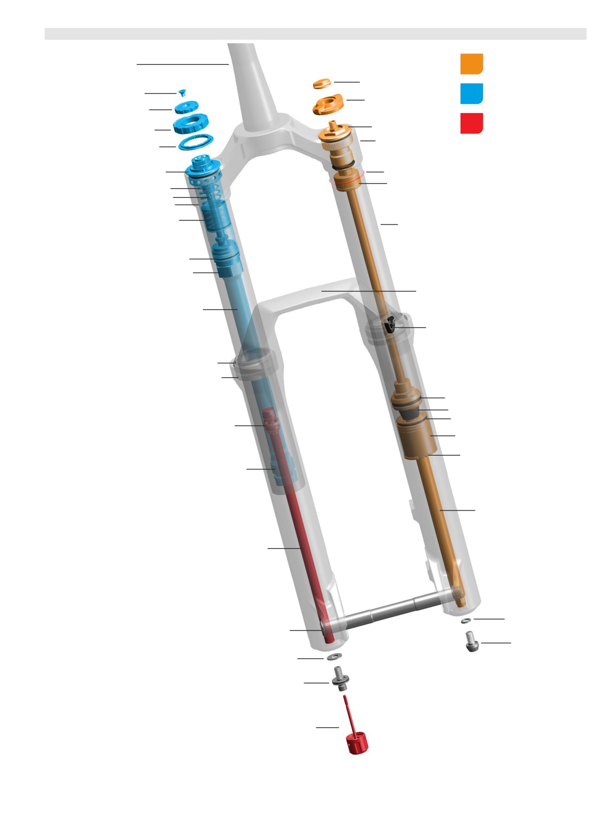
2023+
(A2) ZEB Select+
-
Charger
3
RC
2
- Dual Position Air
Air Spring Assembly
Steerer tube
Air cap
Compression Damper
Retaining screw
Assembly
Travel adjuster knob
Low speed compression (LSC)
adjuster knob
Rebound Damper
High speed compression (HSC)
Air spring top cap
Assembly
adjuster knob
Crown
Detent plate
Compression damper top cap
Sag o-ring
Bottomless Token(s) red (optional)
IFP spring
Bleed port
IFP tube
Internal floating piston (IFP)
Upper tube
Compression damper
IFP tube coupler
Lower leg arch
Damper tube
Brake hose guide
Dust wiper seal
Foam ring
Air spring piston
Top out bumper
Air spring sealhead
Rebound damper piston
Air sealhead spacer
Retaining ring
Rebound damper sealhead
Air spring shaft
Rebound damper shaft
Crush washer
Maxle Stealth
Air spring bottom bolt
Crush washer
Rebound bottom bolt
Rebound adjuster knob
2023+ (A2) ZEB Select+ - Charger 3 RC2 - Dual Position Air
14
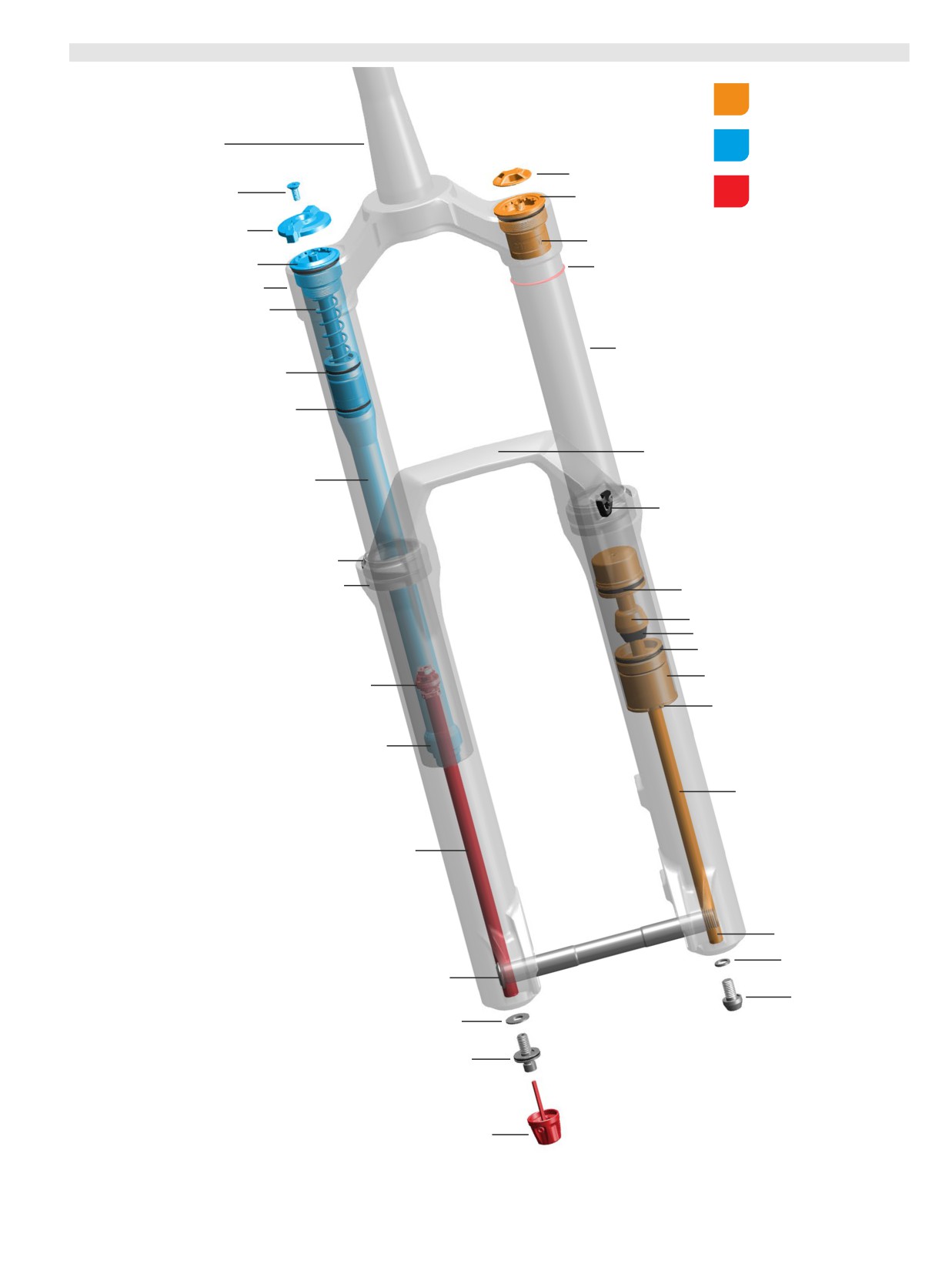
2
023+
(A2) ZEB Select
-
Charger
RC
-
DebonAir+
Air Spring Assembly
Compression Damper
Steerer tube
Assembly
Air cap
Rebound Damper
Retaining screw
Air spring top cap
Assembly
Low speed compression (LSC)
adjuster knob
Bottomless Token(s) 35 mm grey (optional)
Compression damper top cap
Sag o-ring
Crown
Bleed port
Upper tube
Internal floating piston (IFP)
Compression damper
Lower leg arch
Damper tube
Brake hose guide
Dust wiper seal
Foam ring
Air spring piston
Top out cup
Top out bumper
Air spring sealhead
Air sealhead spacer
Rebound damper piston
Retaining ring
Rebound damper sealhead
Air spring shaft
Rebound damper shaft
Air spring shaft insert
Crush washer
Maxle Stealth
Air spring bottom bolt
Crush washer
Rebound bottom bolt
Rebound adjuster knob
2023+ (A2) ZEB Select - Charger RC - DebonAir+
15
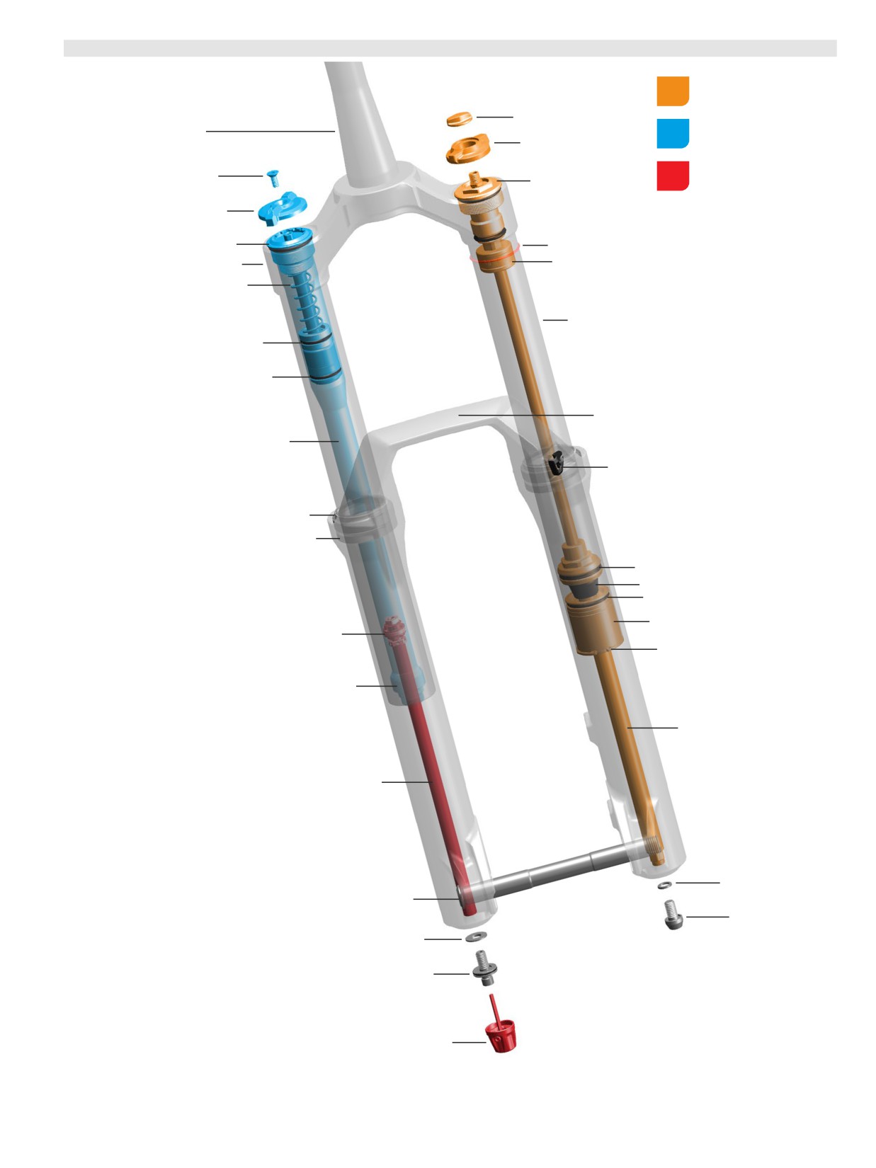
2
023+
(A2) ZEB Select
-
Charger
RC
-
Dual Position Air
Air Spring Assembly
Air cap
Compression Damper
Steerer tube
Assembly
Travel adjuster knob
Rebound Damper
Retaining screw
Air spring top cap
Assembly
Low speed compression (LSC)
adjuster knob
Compression damper top cap
Sag o-ring
Crown
Bottomless Token(s) red (optional)
Bleed port
Upper tube
Internal floating piston (IFP)
Compression damper
Lower leg arch
Damper tube
Brake hose guide
Dust wiper seal
Foam ring
Air spring piston
Top out bumper
Air spring sealhead
Air sealhead spacer
Rebound damper piston
Retaining ring
Rebound damper sealhead
Air spring shaft
Rebound damper shaft
Crush washer
Maxle Stealth
Air spring bottom bolt
Crush washer
Rebound bottom bolt
Rebound adjuster knob
2023+ (A2) ZEB Select - Charger RC - Dual Position Air
16
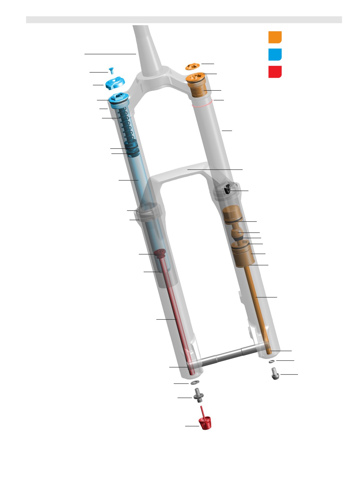
2
023+
(A2) ZEB Base
-
Rush
RC
-
DebonAir+
Air Spring Assembly
Compression Damper
Steerer tube
Assembly
Air cap
Rebound Damper
Retaining screw
Air spring top cap
Assembly
Low speed compression (LSC)
adjuster knob
Bottomless Token(s) 35 mm grey (optional)
Compression damper top cap
Sag o-ring
Crown
Bleed port
Upper tube
Internal floating piston (IFP)
Compression damper
Lower leg arch
Damper tube
Brake hose guide
Dust wiper seal
Foam ring
Air spring piston
Top out cup
Top out bumper
Air spring sealhead
Rebound damper piston
Air sealhead spacer
Retaining ring
Rebound damper sealhead
Air spring shaft
Rebound damper shaft
Air spring shaft insert
Crush washer
Maxle Stealth
Air spring bottom bolt
Crush washer
Rebound bottom bolt
Rebound adjuster knob
2023+ (A2) ZEB Base - Rush RC - DebonAir+
17
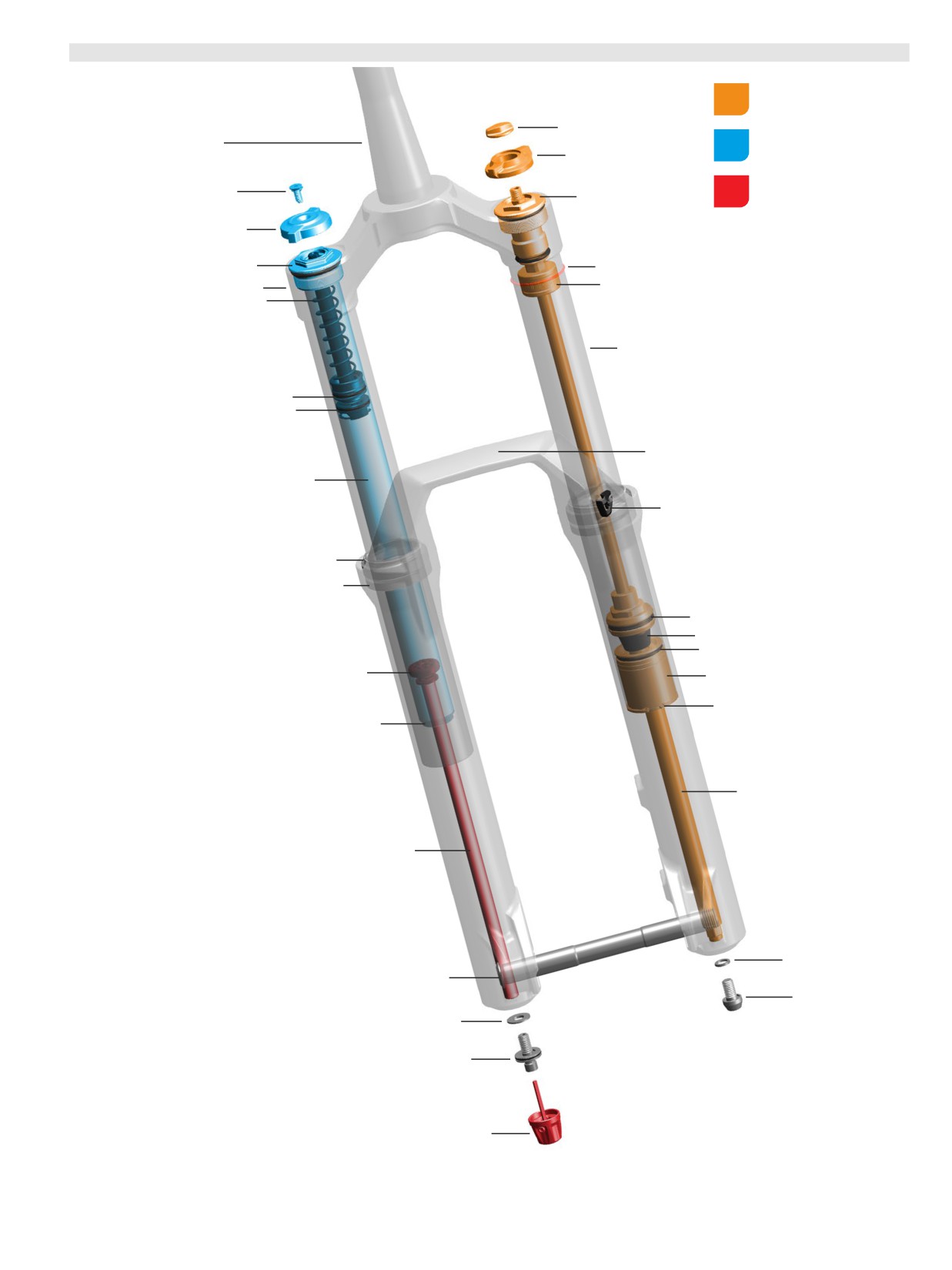
2
023+
(A2) ZEB Base
-
Rush
RC
-
Dual
Position Air
Air Spring Assembly
Air cap
Compression Damper
Steerer tube
Assembly
Travel adjuster knob
Rebound Damper
Retaining screw
Air spring top cap
Assembly
Low speed compression (LSC)
adjuster knob
Compression damper top cap
Sag o-ring
Crown
Bottomless Token(s) red (optional)
Bleed port
Upper tube
Internal floating piston (IFP)
Compression damper
Lower leg arch
Damper tube
Brake hose guide
Dust wiper seal
Foam ring
Air spring piston
Top out bumper
Air spring sealhead
Rebound damper piston
Air sealhead spacer
Retaining ring
Rebound damper sealhead
Air spring shaft
Rebound damper shaft
Crush washer
Maxle Stealth
Air spring bottom bolt
Crush washer
Rebound bottom bolt
Rebound adjuster knob
2023+ (A2) ZEB Base - Rush RC - Dual Position Air
18
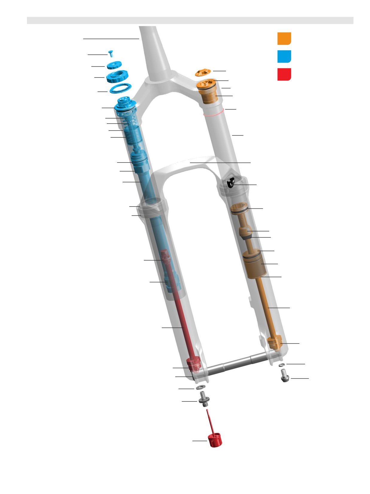
2023+
(D1) Lyrik Ultimate
- Charger
3 RC2
- DebonAir+
Air Spring Assembly
Steerer tube
Compression Damper
Retaining screw
Assembly
Low speed compression (LSC)
adjuster knob
Air cap
Rebound Damper
High speed compression (HSC)
Assembly
adjuster knob
Air spring top cap
Crown
Detent plate
Bottomless Token(s) 35 mm grey (optional)
Compression damper top cap
Sag o-ring
IFP spring
Bleed port
IFP tube
Upper tube
Internal floating piston (IFP)
Compression damper
Lower leg arch
IFP tube coupler
Damper tube
Brake hose guide
Dust wiper seal
Air spring piston
Foam ring
Top out cup
Top out bumper
Air spring sealhead
Rebound damper piston
Air sealhead spacer
Retaining ring
Rebound damper sealhead
Air spring shaft
Rebound damper shaft
ButterCups (air shaft)
Crush washer
ButterCups (damper shaft)
Maxle Stealth
Air spring bottom bolt
Crush washer
Rebound bottom bolt
Rebound adjuster knob
2023+ (D1) Lyrik Ultimate - Charger 3 RC2 - DebonAir+
19
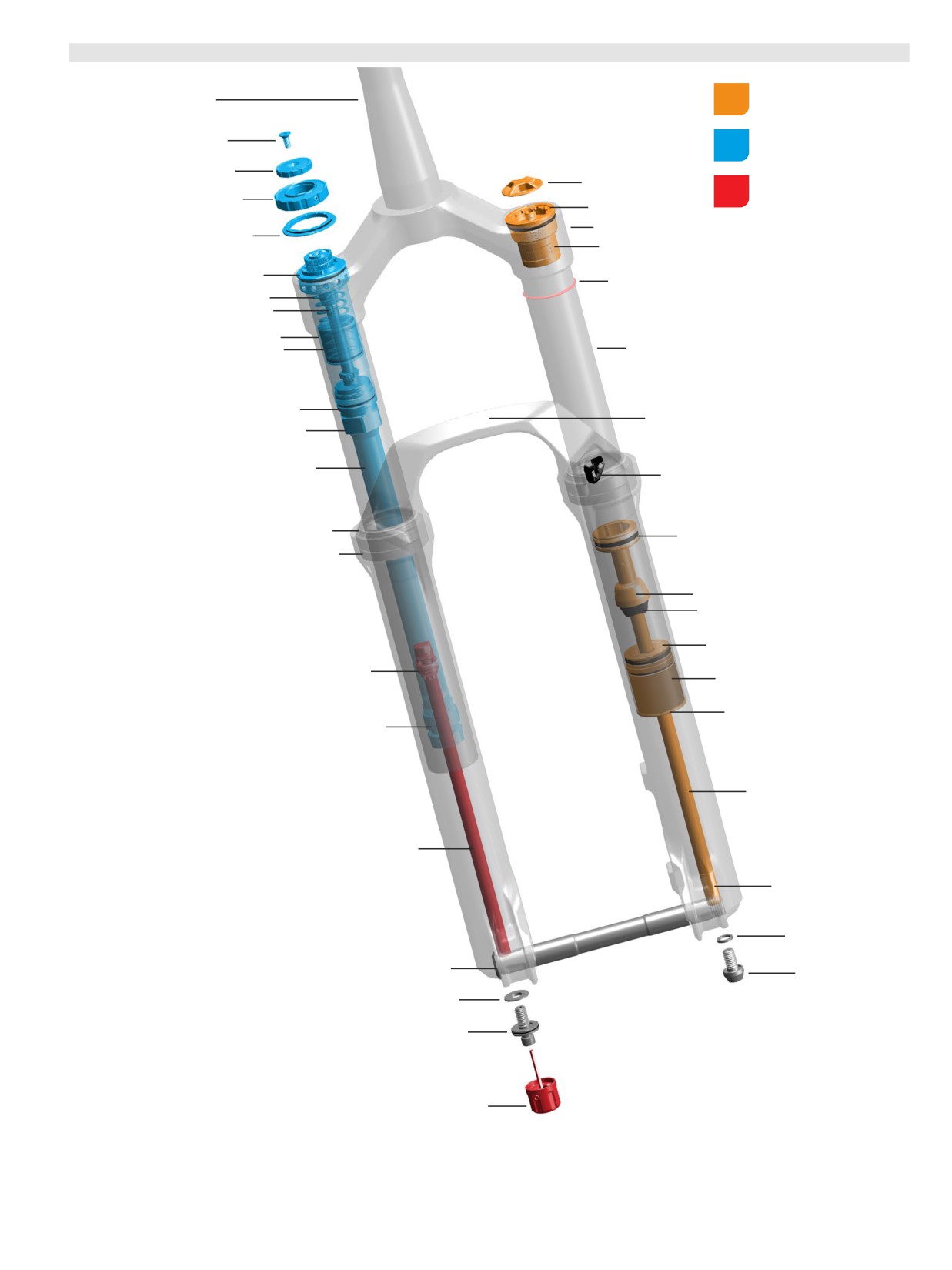
2023+
(D1) Lyrik Select+
- Charger
3 RC2
- DebonAir+
Air Spring Assembly
Steerer tube
Compression Damper
Retaining screw
Assembly
Low speed compression (LSC)
adjuster knob
Air cap
Rebound Damper
High speed compression (HSC)
Assembly
adjuster knob
Air spring top cap
Crown
Detent plate
Bottomless Token(s) 35 mm grey (optional)
Compression damper top cap
Sag o-ring
IFP spring
Bleed port
IFP tube
Internal floating piston (IFP)
Upper tube
Compression damper
Lower leg arch
IFP tube coupler
Damper tube
Brake hose guide
Dust wiper seal
Air spring piston
Foam ring
Top out cup
Top out bumper
Air spring sealhead
Rebound damper piston
Air sealhead spacer
Retaining ring
Rebound damper sealhead
Air spring shaft
Rebound damper shaft
Air spring shaft insert
Crush washer
Maxle Stealth
Air spring bottom bolt
Crush washer
Rebound bottom bolt
Rebound adjuster knob
2023+ (D1) Lyrik Select+ - Charger 3 RC2 - DebonAir+
20
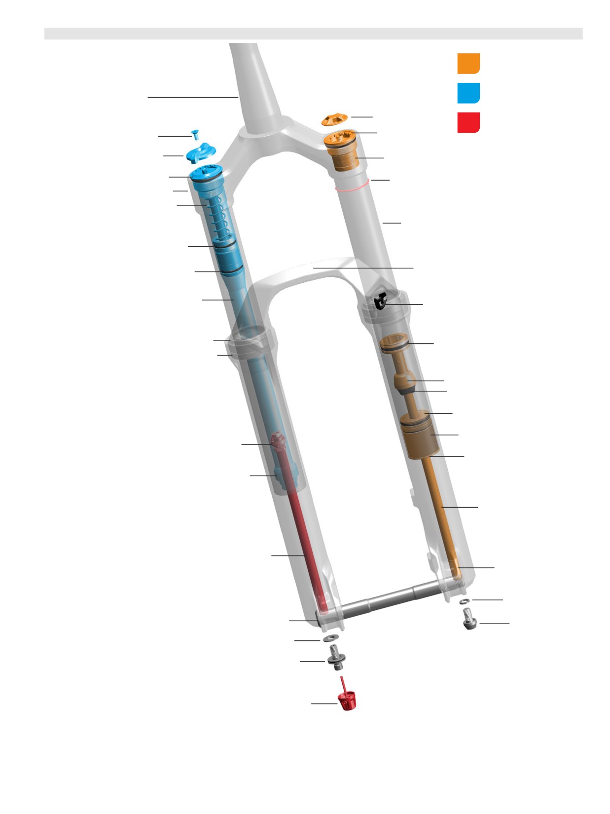
2
0
23+
(D1) Lyrik Select
-
Charger
RC
-
DebonAir+
Air Spring Assembly
Compression Damper
Steerer tube
Assembly
Air cap
Rebound Damper
Assembly
Air spring top cap
Retaining screw
Low speed compression (LSC)
adjuster knob
Bottomless Token(s) 35 mm grey (optional)
Compression damper top cap
Sag o-ring
Crown
Bleed Port
Upper tube
Internal floating piston (IFP)
Lower leg arch
Compression damper
Damper tube
Brake hose guide
Dust wiper seal
Air spring piston
Foam ring
Top out cup
Top out bumper
Air spring sealhead
Air sealhead spacer
Rebound damper piston
Retaining ring
Rebound damper sealhead
Air spring shaft
Rebound damper shaft
Air spring shaft insert
Crush washer
Maxle Stealth
Air spring bottom bolt
Crush washer
Rebound bottom bolt
Rebound adjuster knob
2023+ (D1) Lyrik Select - Charger RC - DebonAir+
21
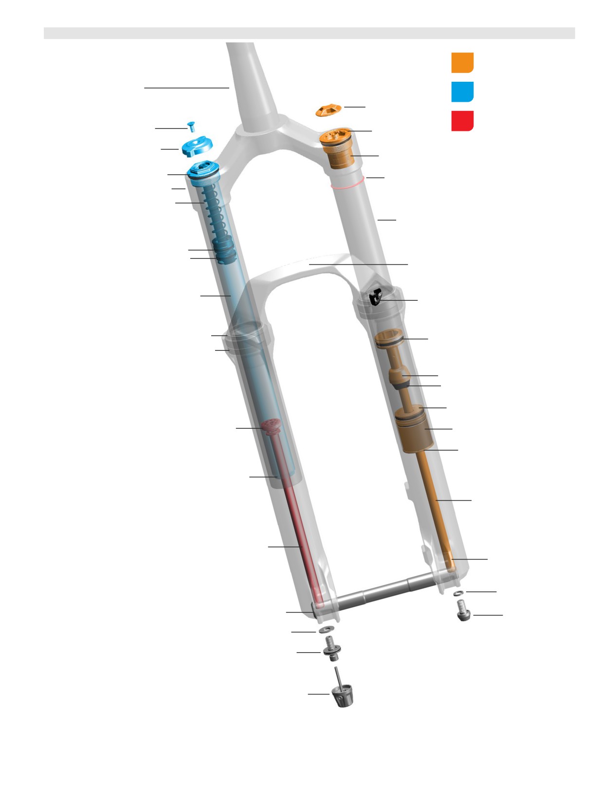
2
0
23+
(D1) Lyrik Base
-
Rush
RC
-
DebonAir+
Air Spring Assembly
Compression Damper
Steerer tube
Assembly
Air cap
Rebound Damper
Assembly
Retaining screw
Air spring top cap
Low speed compression (LSC)
adjuster knob
Bottomless Token(s) 35 mm grey (optional)
Compression damper top cap
Sag o-ring
Crown
Bleed Port
Upper tube
Internal floating piston (IFP)
Compression damper
Lower leg arch
Damper tube
Brake hose guide
Dust wiper seal
Air spring piston
Foam ring
Top out cup
Top out bumper
Air spring sealhead
Rebound damper piston
Air sealhead spacer
Retaining ring
Rebound damper sealhead
Air spring shaft
Rebound damper shaft
Air spring shaft insert
Crush washer
Maxle Stealth
Air spring bottom bolt
Crush washer
Rebound bottom bolt
Rebound adjuster knob
2023+ (D1) Lyrik Base - Rush RC - DebonAir+
22
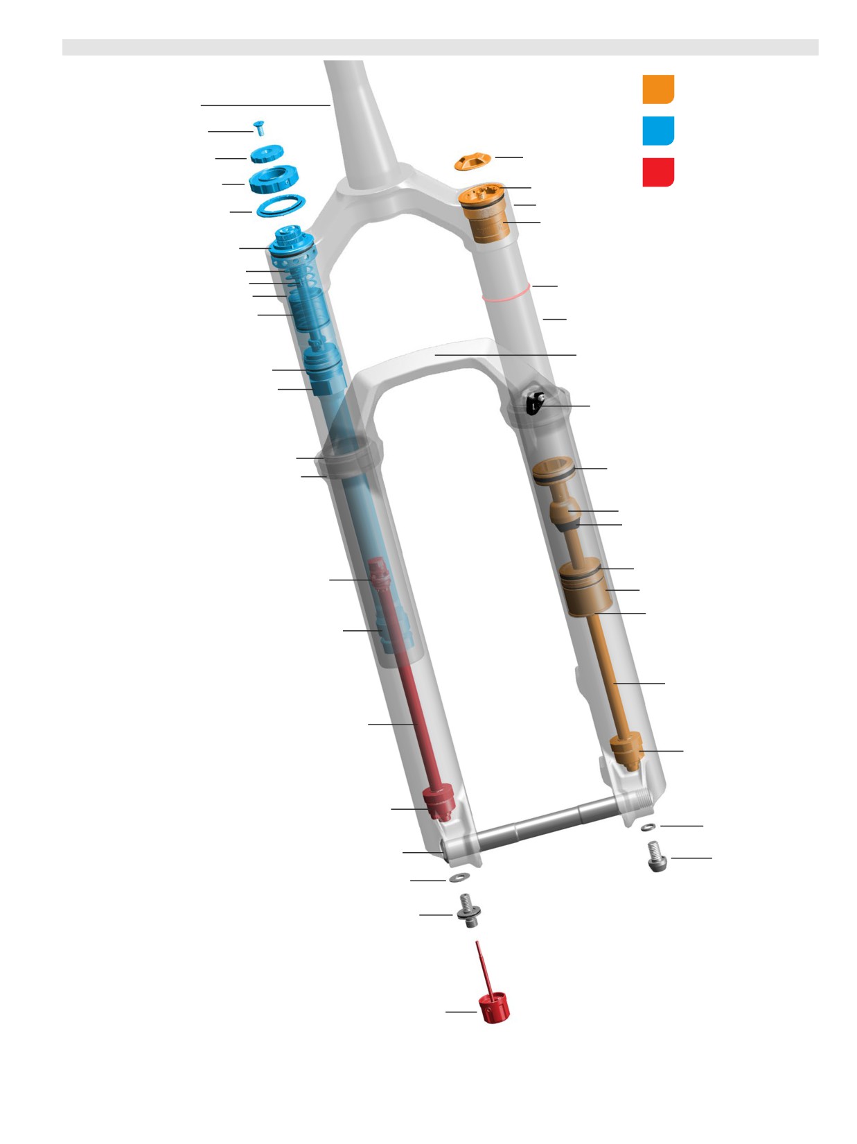
2023+
(C1) Pike Ultimate
-
Charger
3
RC
2
- DebonAir+
Air Spring Assembly
Steerer tube
Compression Damper
Retaining screw
Assembly
Low speed compression (LSC)
Air cap
adjuster knob
Rebound Damper
High speed compression (HSC)
Assembly
adjuster knob
Air spring top cap
Crown
Detent plate
Bottomless Token(s) 35 mm grey (optional)
Compression damper top cap
IFP spring
Bleed port
Sag o-ring
IFP tube
Internal floating piston (IFP)
Upper tube
Lower leg arch
Compression damper
IFP tube coupler
Brake hose guide
Dust wiper seal
Air spring piston
Foam ring
Top out cup
Top out bumper
Air spring sealhead
Rebound damper piston
Air sealhead spacer
Retaining ring
Rebound damper sealhead
Air spring shaft
Rebound damper shaft
ButterCups (air shaft)
ButterCups (damper shaft)
Crush washer
Maxle Stealth
Air spring bottom bolt
Crush washer
Rebound bottom bolt
Rebound adjuster knob
2023+ (C1) Pike Ultimate - Charger 3 RC2 - DebonAir+
23
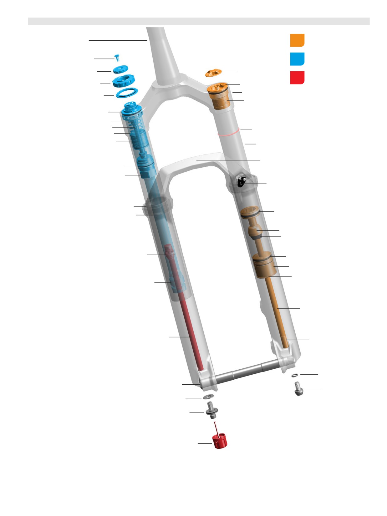
2023+
(C1) Pike Select+
-
Charger
3
RC
2
-
DebonAir+
Air Spring Assembly
Steerer tube
Compression Damper
Retaining screw
Assembly
Low speed compression (LSC)
Air cap
adjuster knob
Rebound Damper
High speed compression (HSC)
Assembly
adjuster knob
Air spring top cap
Crown
Detent plate
Bottomless Token(s) 35 mm grey (optional)
Compression damper top cap
IFP spring
Bleed port
Sag o-ring
IFP tube
Internal floating piston (IFP)
Upper tube
Lower leg arch
Compression damper
IFP tube coupler
Brake hose guide
Dust wiper seal
Air spring piston
Foam ring
Top out cup
Top out bumper
Rebound damper piston
Air spring sealhead
Air sealhead spacer
Retaining ring
Rebound damper sealhead
Air spring shaft
Rebound damper shaft
Air spring shaft insert
Crush washer
Maxle Stealth
Air spring bottom bolt
Crush washer
Rebound bottom bolt
Rebound adjuster knob
2023+ (C1) Pike Select+ - Charger 3 RC2 - DebonAir+
24
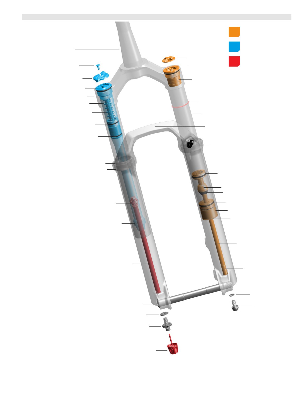
2
0
23+
(C1) Pike Select
-
Charger
RC
-
DebonAir+
Air Spring Assembly
Compression Damper
Steerer tube
Assembly
Air cap
Rebound Damper
Assembly
Retaining screw
Air spring top cap
Low speed compression (LSC)
adjuster knob
Bottomless Token(s) 35 mm grey (optional)
Compression damper top cap
Crown
Sag o-ring
Bleed Port
IFP spring
Upper tube
Internal floating piston (IFP)
Lower leg arch
Compression damper
Brake hose guide
Dust wiper seal
Foam ring
Air spring piston
Top out cup
Top out bumper
Rebound damper piston
Air spring sealhead
Air sealhead spacer
Retaining ring
Rebound damper sealhead
Air spring shaft
Rebound damper shaft
Air spring shaft insert
Crush washer
Maxle Stealth
Air spring bottom bolt
Crush washer
Rebound bottom bolt
Rebound adjuster knob
2023+ (C1) Pike Select - Charger RC - DebonAir+
25
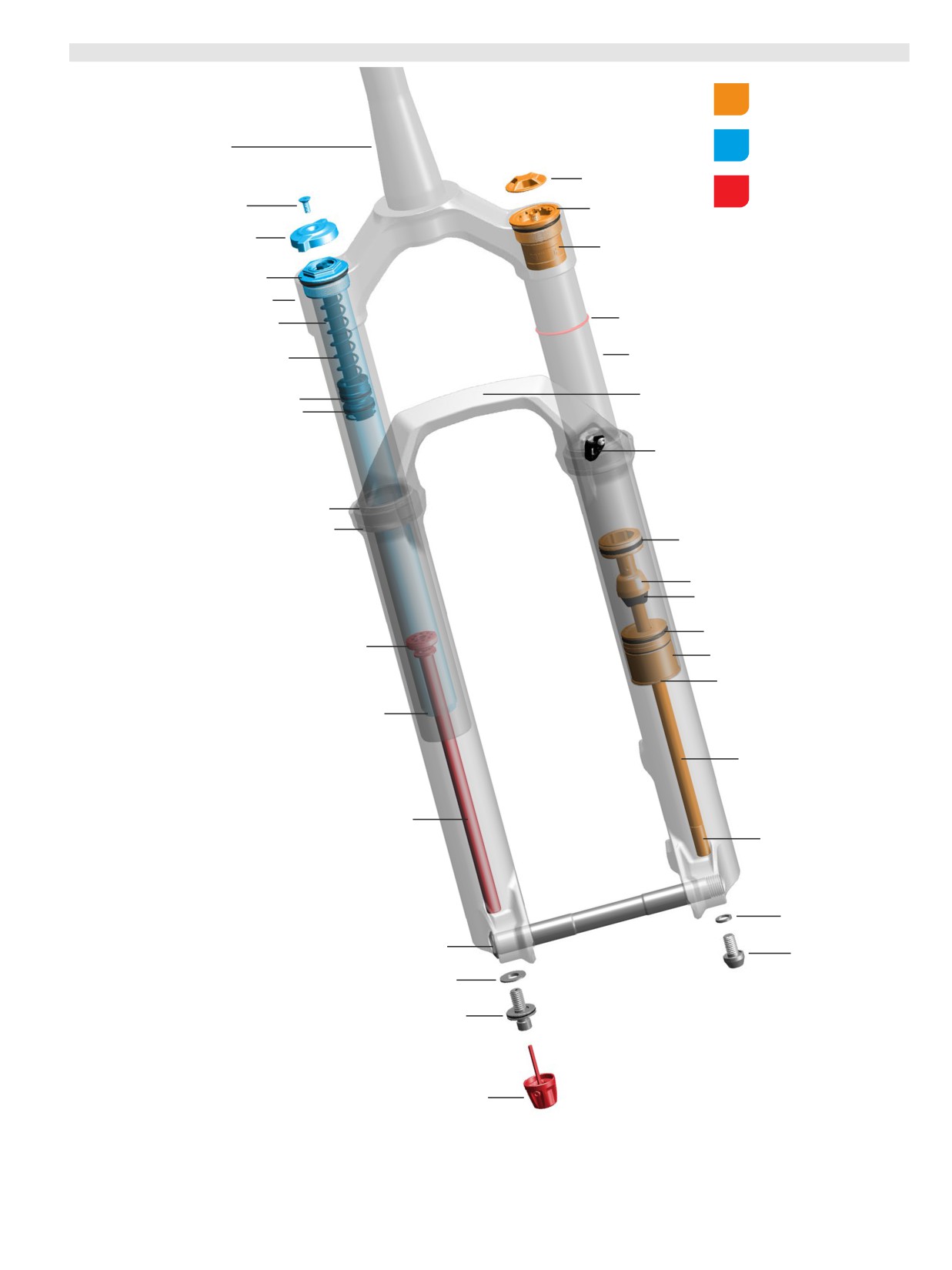
2
0
23+
(C1) Pike Base
-
Rush
RC
-
DebonAir+
Air Spring Assembly
Compression Damper
Steerer tube
Assembly
Air cap
Rebound Damper
Assembly
Retaining ring
Air spring top cap
Low speed compression (LSC)
adjuster knob
Bottomless Token(s) 35 mm grey (optional)
Compression damper top cap
Crown
Sag o-ring
Bleed port
IFP spring
Upper tube
Lower leg arch
Internal floating piston (IFP)
Compression damper
Brake hose guide
Dust wiper seal
Foam ring
Air spring piston
Top out cup
Top out bumper
Air spring sealhead
Rebound damper piston
Air sealhead spacer
Retaining ring
Rebound damper sealhead
Air spring shaft
Rebound damper shaft
Air spring shaft insert
Crush washer
Maxle Stealth
Air spring bottom bolt
Crush washer
Rebound bottom bolt
Rebound adjuster knob
2023+ (C1) Pike Base - Rush RC - DebonAir+
26
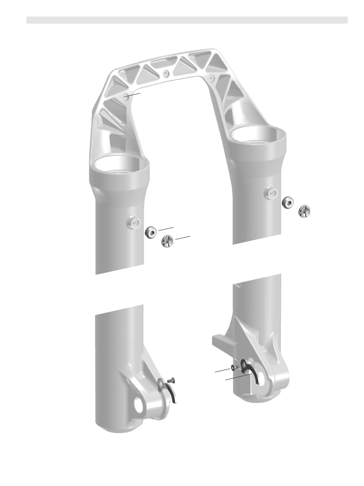
Lower Leg Features
- ZEB, Lyrik, Pike
Fender mount (x3)
Pressure Relief Valve Plug (x2) - Select, Base
Pressure Relief Valve (x2) - Ultimate, Select+
Upgrade kit available for: Select, Base
Bolt (x2)
Dropout Adapter (x2)
27
Lower Leg Features - ZEB, Lyrik, Pike
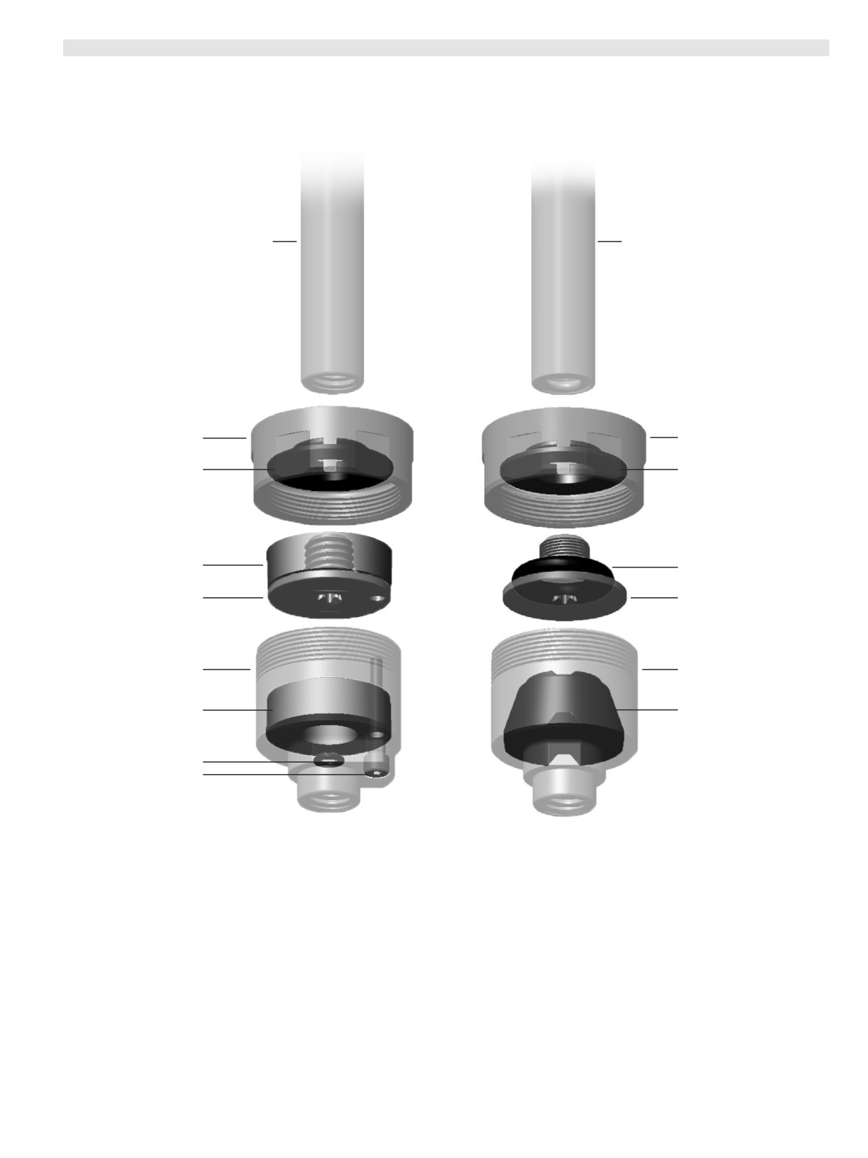
ButterCups
- ZEB, Lyrik, Pike
- Ultimate
- Charger
3 RC2 and DebonAir+
Damper shaft (Ultimate - Charger 3 RC2)
Air spring shaft (Ultimate - DebonAir+)
ZEB (2023+ / A2+), Lyrik (2023+ / D1+), and
ZEB (2023+ / A2+), Lyrik (2023+ / D1+), and
Pike (2023+ / C1+) Ultimate Charger 3 RC2
Pike (2023+ / C1+) DebonAir+ with ButterCups
Damper with ButterCups upgrade kits are
air spring upgrade kits are available and can
available and can be installed into
be installed into Select+, Select, and Base
Select+, Select, and Base fork models.
fork models.
Damper side ButterCups is NOT compatible
Air spring side ButterCups is NOT compatible
with Charger RC and Rush RC dampers.
with Dual Position Air air spring.
Upper ButterCups housing
Upper ButterCups housing
Bushing
Bushing
Upper bumper
O-ring
ButterCups shaft end plate
ButterCups shaft end plate
Lower ButterCups housing
Lower ButterCups housing
Lower bumper
Bumper
O-ring
Lower housing alignment bolt
ButterCups - ZEB, Lyrik, Pike - Ultimate - Charger 3 RC2 and DebonAir+
28
Optional Upgrade
- Pressure Relief Valve
(PRV) Installation
- Select, Base
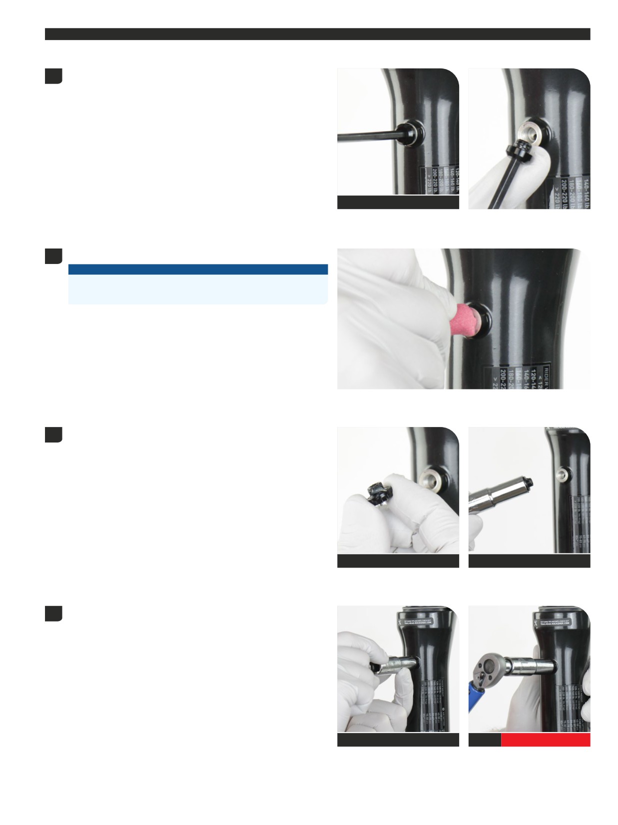
Pressure Relief Valves (PRV) can be installed onto ZEB (A2), Lyrik (D1), and Pike (C1) Select and Base model forks as a lower leg upgrade at any time.
Remove each PRV plug.
1
Pressurized air and oil may escape the lower leg when the plugs are
removed. This is normal.
4 mm
Clean the lower leg threads.
2
NOTICE
Do not spray cleaning fluid into the PRV bolt hole and into the
lower leg.
Apply grease to the new PRV assembly threads.
3
RockShox Dynamic Seal Grease
10 mm
Install each PRV assembly and tighten them to the specified torque.
4
Wipe away any excess grease.
10 mm
10 mm
2 N·m (17 in-lb)
Optional Upgrade - Pressure Relief Valve (PRV) Installation - Select, Base
29
Lower Leg Removal and Service
50/200 Hour Service Lower Leg Removal
ZEB is pictured in this section. Procedures are the same for Lyrik and Pike unless otherwise described.
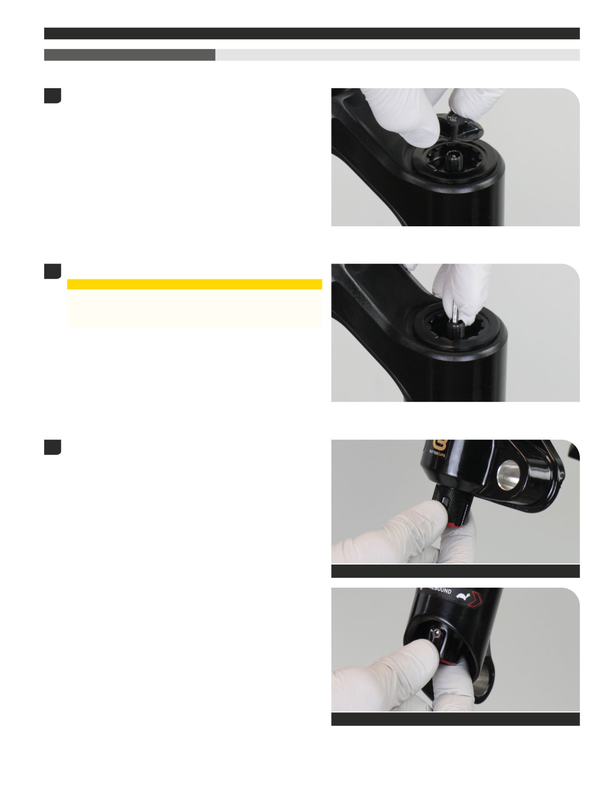
Remove the air valve cap.
1
Depress the Schrader valve and release all air pressure.
2
⚠CAUTION - EYE HAZARD
Verify all pressure is removed from the fork before proceeding.
Failure to do so can result in injury and/or damage to the fork. Wear
safety glasses.
Turn the rebound adjuster knob counterclockwise until it stops. This is
3
the full open/fast rebound setting.
RC2
Counterclockwise - Full Open Setting
RC
Counterclockwise - Full Open Setting
Lower Leg Removal and Service
30
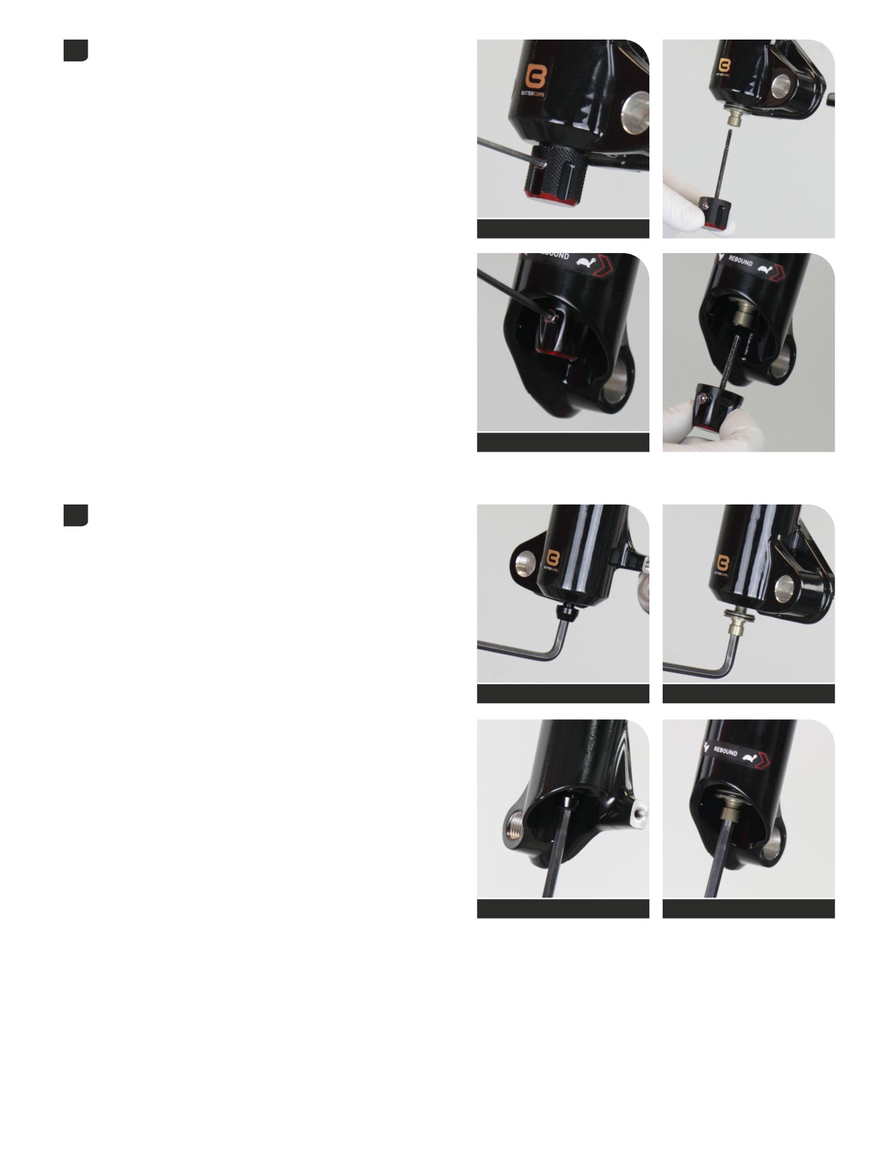
Loosen the set screw and remove the rebound damper adjuster knob.
4
2.5 mm
RC2
2.5 mm
RC
Place an oil pan beneath the fork to catch the draining oil.
5
Loosen both bottom bolts 3 to 4 turns.
5 mm
Spring side
5 mm
Damper side
5 mm
Spring side
5 mm
Damper side
Lower Leg Removal
31
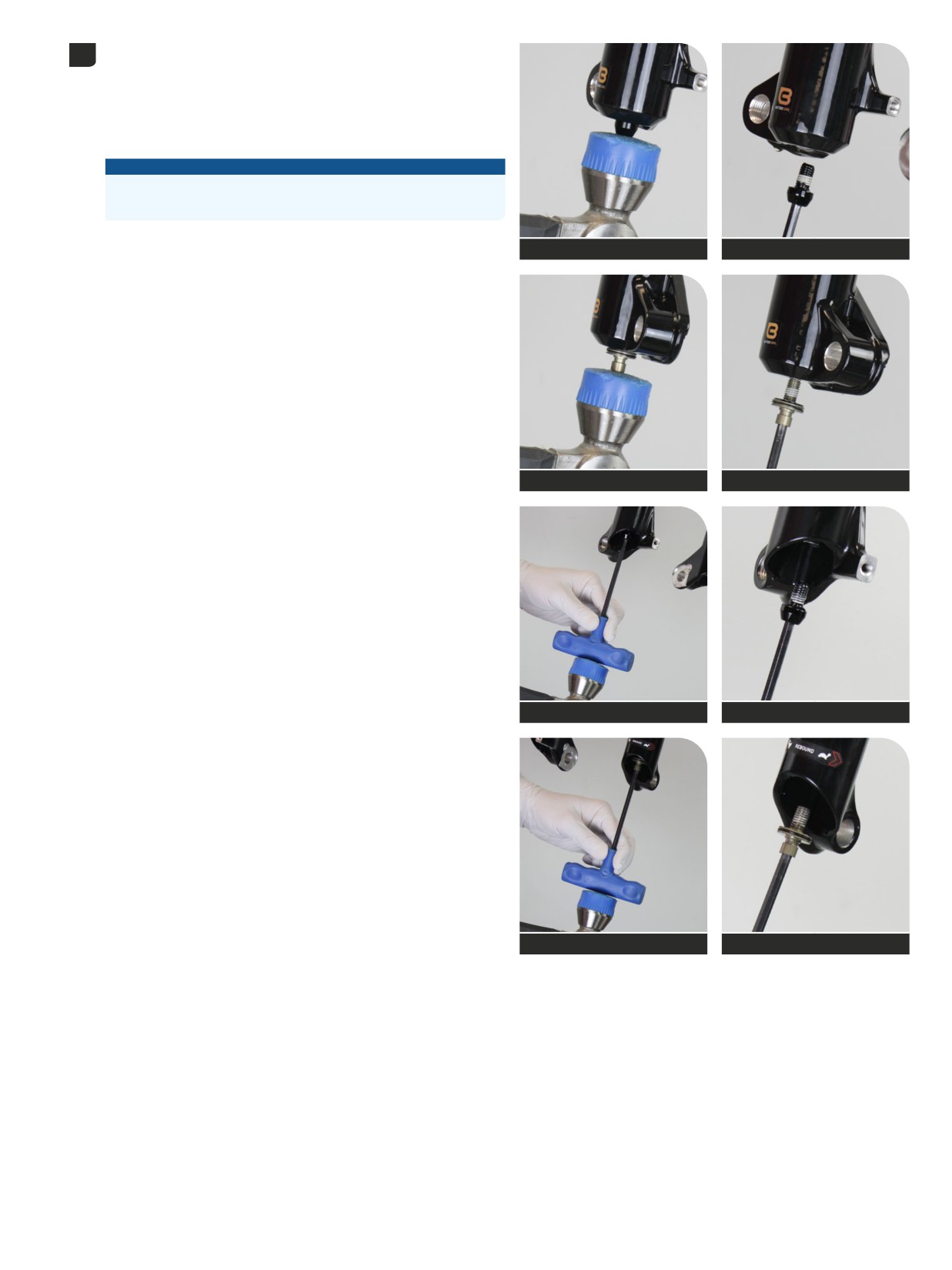
Strike each bolt head to dislodge the spring and damper shaft
6
ButterCups from the lower leg. The bolt head should contact the
bottom of the lower leg.
Remove each bottom bolt. Clean each bolt and set them aside.
Pike 27.5" and 29", Lyrik 29": Insert a 5 mm hex wrench into the bolt,
and tap the wrench to avoid damage to the lower leg.
NOTICE
Do not strike the fork lower leg with mallet as this could damage the
lower leg.
Mallet
Spring side
5 mm
Spring side
Mallet
Damper side
5 mm
Damper side
Mallet - 5 mm hex
Spring side
5 mm
Spring side
Mallet - 5 mm hex
Damper side
5 mm
Damper side
Lower Leg Removal
32
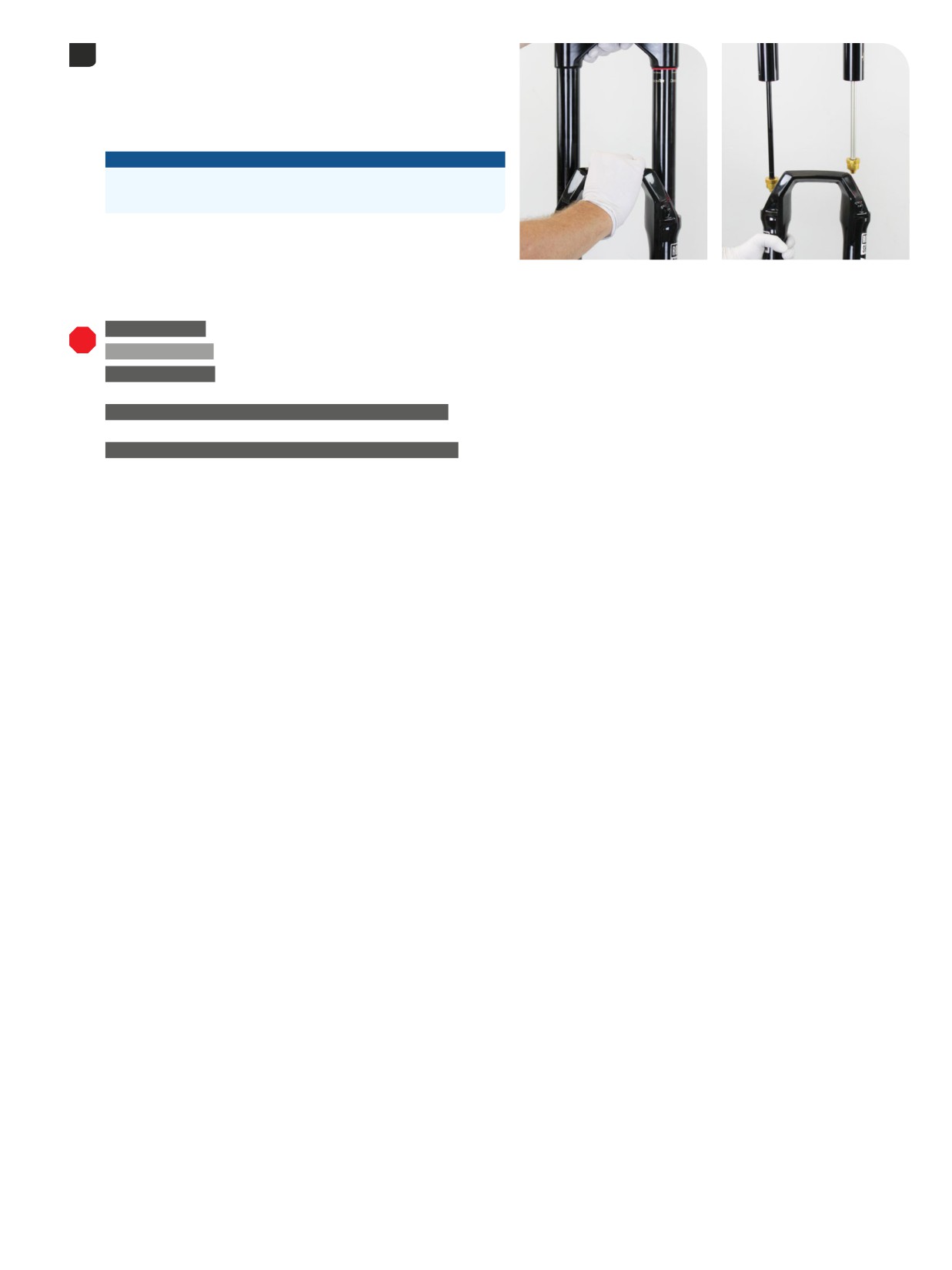
Firmly pull the lower leg downward until fluid begins to drain. Continue
7
pulling downward to remove the lower leg.
If the lower leg does not slide off of the upper tube or if oil does not
drain from either side, the press fit of the shaft(s) into the lower leg may
still be engaged. Reinstall the bottom bolts 2 to 3 turns and repeat the
previous step.
NOTICE
Do not strike the fork arch with any tool when removing the lower
leg as this could damage the lower leg.
50 Hour Service Continue the 50 Hour Service with Lower Leg Service.
200 Hour Service Continue the 200 Hour Service with Lower Leg Seal Service.
TRAVEL CHANGE
Ultimate, Select+, Select, Base: For DebonAir+ air spring travel change, the original air spring assembly must be removed.
Proceed to Air Spring Removal.
UPGRADE - DEBONAIR+ AIR SPRING WITH BUTTERCUPS
Select+, Select, Base: For DebonAir+ air spring replacement, the original air
spring assembly must be removed. Proceed to Air Spring Removal.
UPGRADE - CHARGER 3 RC2 DAMPER WITH BUTTERCUPS
Select+, Select, Base: For damper replacement, the original damper assembly
must be removed. Proceed to the appropriate Damper Service section for damper removal and installation procedures. Follow the applicable
steps to remove the original damper and insall the upgrade damper.
Select+: Damper Service - Charger 3 RC2
Select: Damper Service - Charger RC
Base: Damper Service - Rush RC
Lower Leg Removal
33
50 Hour Service
Lower Leg Service
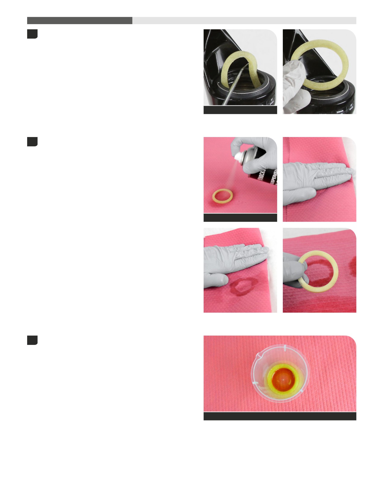
Remove the foam rings.
1
Pick
Clean the foam rings.
2
Replace the foam rings if worn, damaged, or excessively contaminated.
RockShox Suspension Cleaner
Soak the foam rings in Maxima PLUSH Dynamic Suspension Lube
3
Light.
Maxima PLUSH Dynamic Suspension Lube Light
Lower Leg Service
34
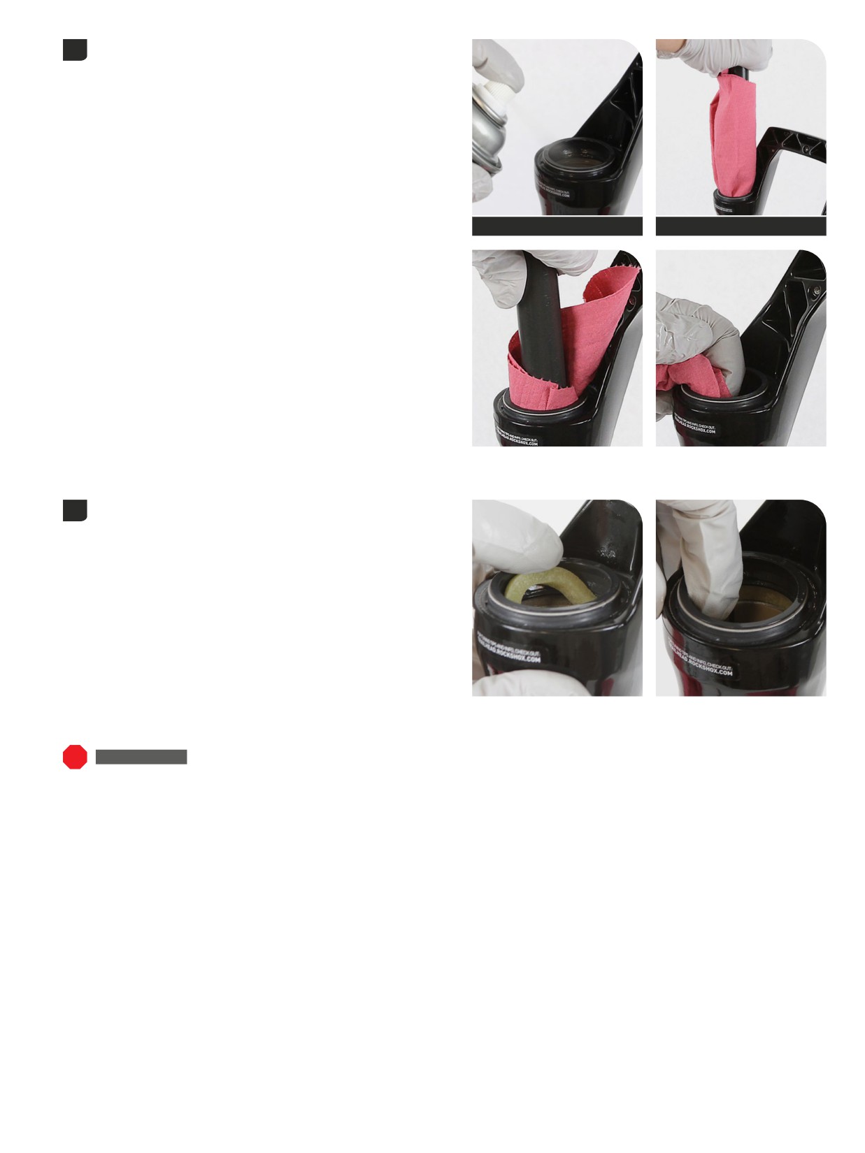
Clean the inside and outside of the lower leg.
4
Clean the wiper seals.
RockShox Suspension Cleaner
Dowel
Install the foam rings under the wiper seals.
5
Confirm the foam rings are installed evenly and square in the space
under the wiper seals and do not protrude out of the groove.
50 Hour Service Continue the 50 Hour Service with Lower Leg Installation.
Lower Leg Service
35
200 Hour Service
Lower Leg Seal Service
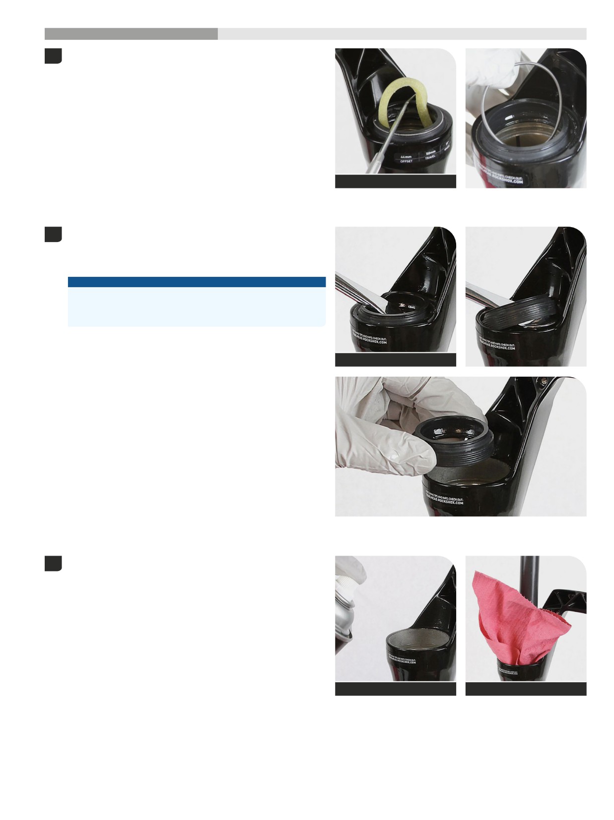
Remove and discard the foam rings.
1
Remove the outer wire springs from the dust wiper seals.
Pick
Stabilize the lower leg on a bench top. Place the tip of a downhill
2
tire lever under the wiper seal. Press down on the downhill tire lever
handle to remove the seal.
Repeat on the other side. Discard the wiper seals.
NOTICE
Keep the lower leg stable. Do not allow the lower leg to twist in
opposite directions, compress toward each other, or be pulled apart.
This will damage the lower leg.
Downhill tire lever
Clean the inside and outside of the lower leg.
3
RockShox Suspension Cleaner
Dowel
Lower Leg Seal Service
36
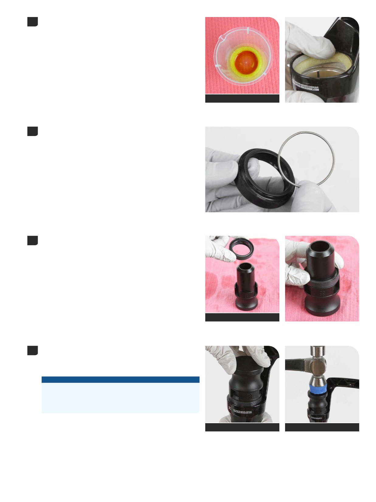
Soak new foam rings in Maxima PLUSH Dynamic Suspension Lube
4
Light.
Install the new foam rings into the lower leg.
Maxima PLUSH Dynamic Suspension
Lube Light
Remove the outer wire spring from each new dust wiper seal and set
5
them aside.
Insert the narrow end of a new wiper seal into the recessed end of the
6
RockShox Dust Seal Installation Tool.
38 mm - ZEB
35 mm - Lyrik and Pike
RockShox Dust Seal Installation Tool
Stabilize the lower leg on a bench top. Hold the lower leg steady and
7
press, or tap with a mallet, the wiper seal into the lower leg until the top
of the seal is flush with the top of the lower leg.
Repeat on the other side.
NOTICE
Only press, or tap with a mallet, the wiper seal into the lower leg
until it is flush with the top surface of the lower leg. Pressing the
wiper seal below the top surface of the lower leg will compress the
foam ring.
RockShox Dust Seal Installation Tool
Mallet
Lower Leg Seal Service
37
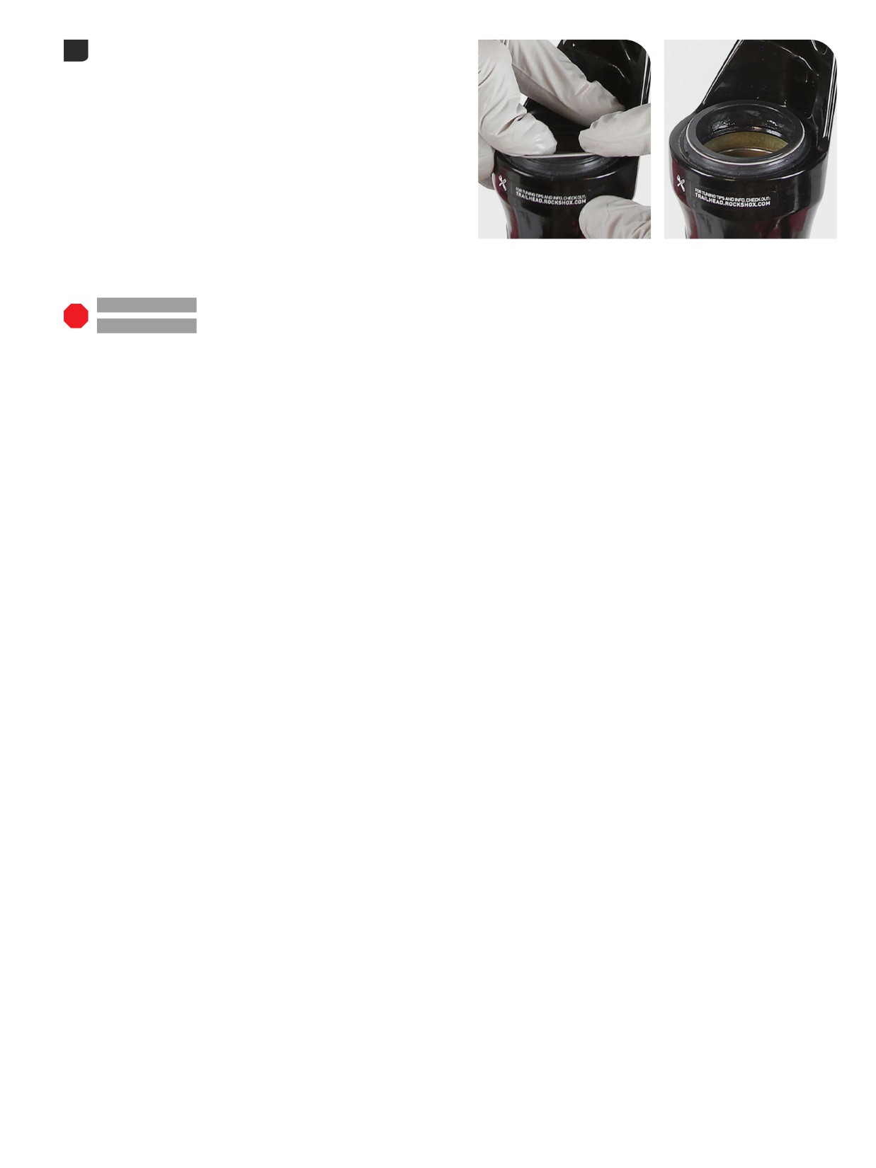
Install the outer wire springs.
8
200 Hour Service
DebonAir+ - Air Spring Service:
Continue with
Air Spring Service, Travel Change, and ButterCups Upgrade.
200 Hour Service
ZEB with Dual Position Air - Air Spring Service:
Continue with
Dual Position Air (DPA) - ZEB - Air Spring Service.
Lower Leg Seal Service
38
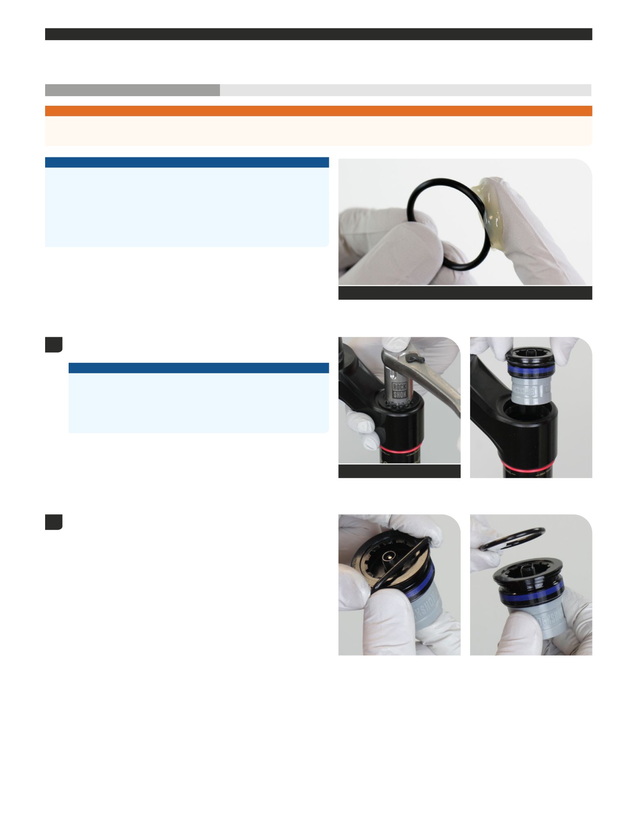
DebonAir+
- Air Spring Service, Travel Change, and ButterCups Upgrade
A ZEB Ultimate air spring assembly is pictured in this section. Procedures are the same for ZEB, Lyrik, and Pike unless otherwise pictured or
described.
200 Hour Service
Air Spring Removal
⚠WARNING - EYE HAZARD
Verify all pressure is removed from the fork before proceeding. Depress the Schrader valve again to remove any remaining air pressure. Failure to
do so can result in injury and/or damage to the fork.
NOTICE
Inspect each part for scratches. Do not scratch any sealing surfaces when
servicing your suspension. Scratches can cause leaks.
When replacing seals and o-rings, use your fingers or a pick to remove the
seal or o-ring. Spray RockShox Suspension Cleaner or isopropyl alcohol
onto each part and clean with a clean lint-free shop towel.
Apply SRAM Butter Grease to the new seals and o-rings.
SRAM Butter Grease
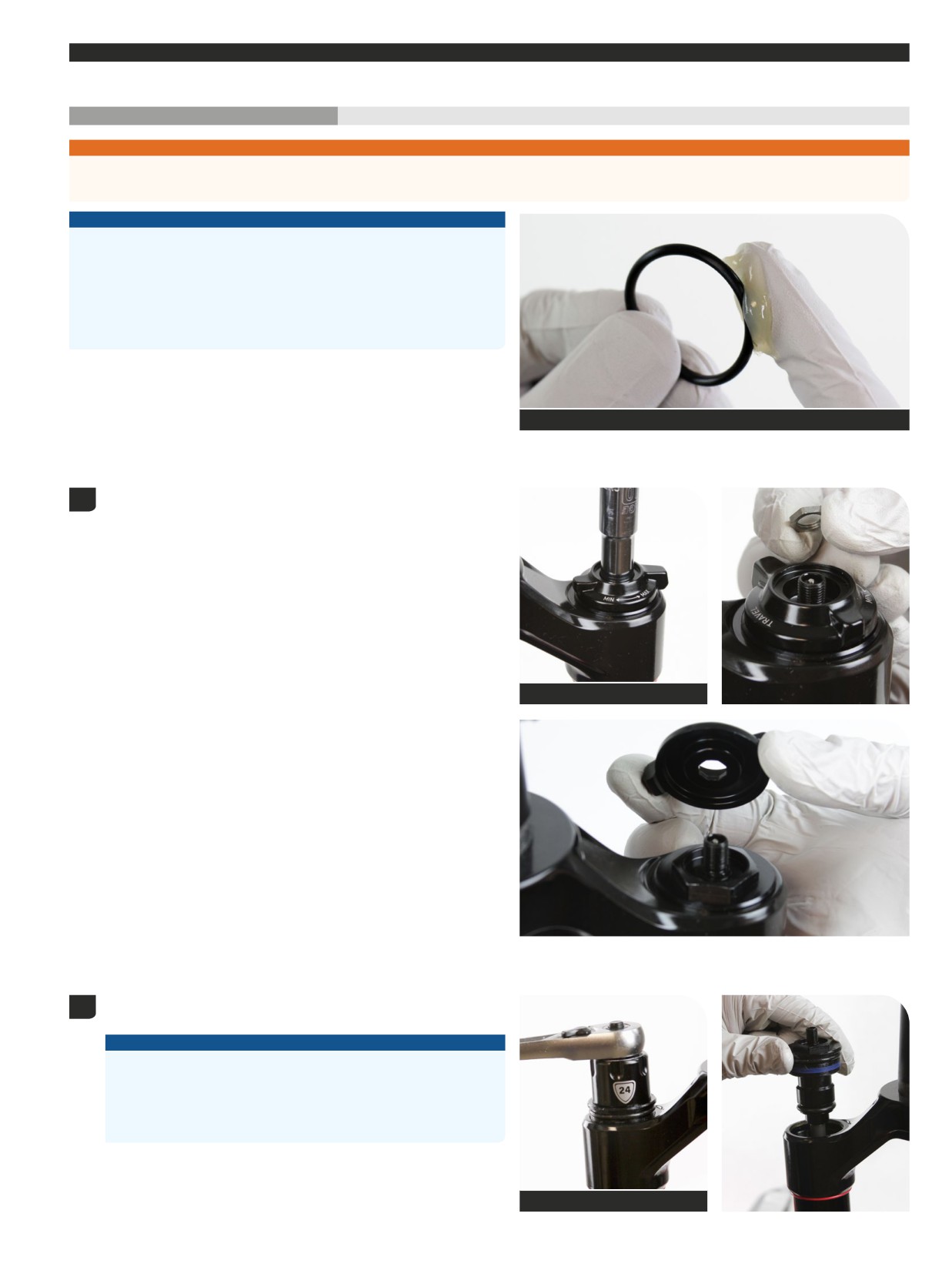
Remove the air spring top cap. Press down firmly when loosening the
1
top cap.
NOTICE
The fork top caps are tightened to a high torque value. Ensure the
fork is held securely in the bicycle stand. To avoid damage to the
top cap, press the top cap / cassette tool squarely and firmly down
when loosening. Use a socket wrench with a long handle for extra
leverage.
Clean the upper tube threads.
Top cap / Cassette tool
Remove the top cap o-ring and discard it.
2
Apply grease to a new o-ring and install it.
39
DebonAir+ - Air Spring Service, Travel Change, and ButterCups Upgrade
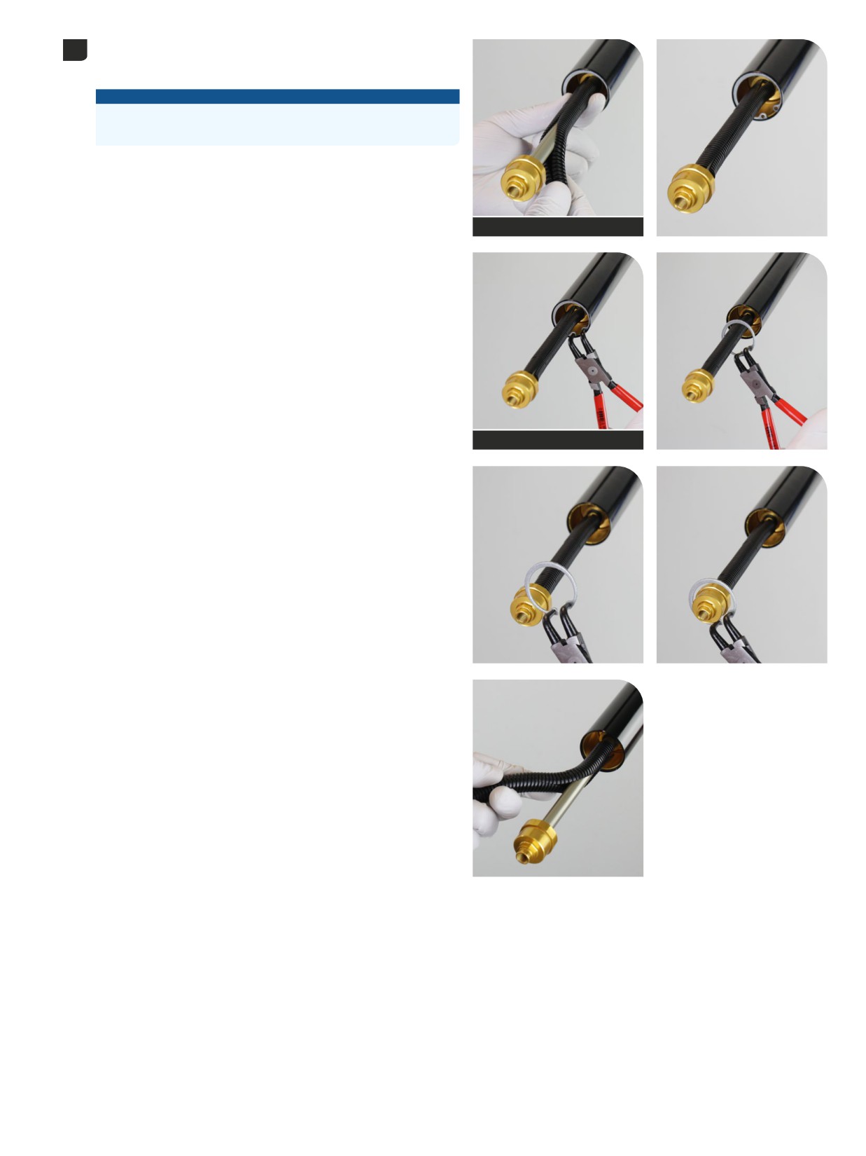
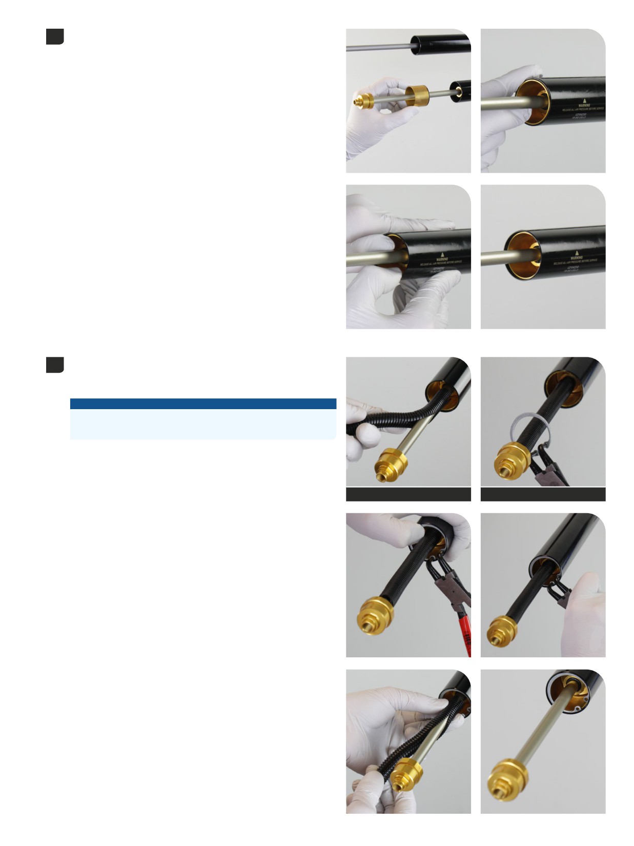
Install a section of protective split plastic tube, or a shop towel, around
3
the air spring shaft to protect the shaft surface during removal. Remove
the plastic tube after retaining ring removal.
NOTICE
Do not scratch the air spring shaft. Scratches can cause air to leak.
Replace the air spring assembly if a scratch is visible.
ZEB: Remove the retaining ring.
Ultimate pictured.
Remove the split plastic tube or shop towel from the shaft.
Split plastic tube
Retaining ring pliers
Air Spring Removal
40
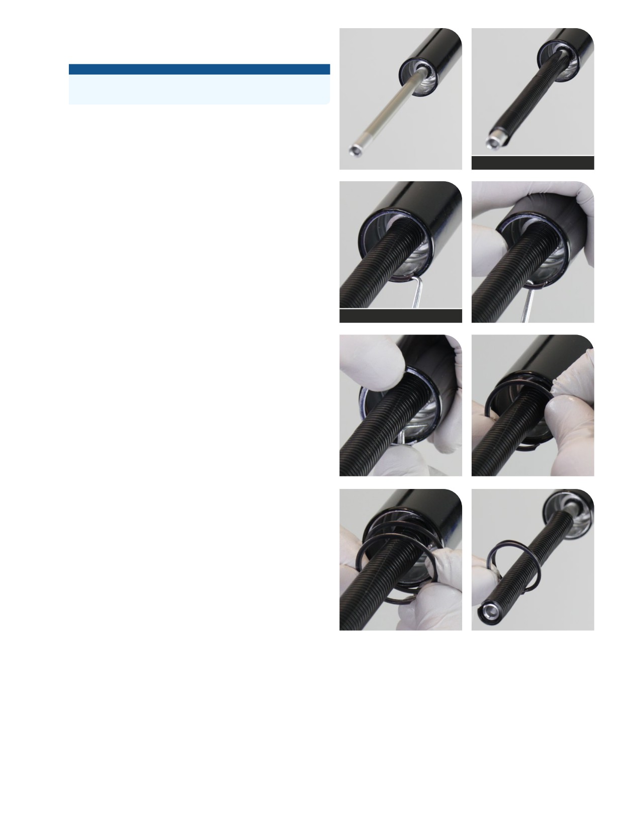
Install a section of protective split plastic tube, or a shop towel, around
the air spring shaft to protect the shaft surface during removal. Remove
the plastic tube after retaining ring removal.
NOTICE
Do not scratch the air spring shaft. Scratches can cause air to leak.
Replace the air spring assembly if a scratch is visible.
Lyrik / Pike: Remove the retaining ring.
Select+, Select, Base pictured.
Remove the split plastic tube or shop towel from the shaft.
Split plastic tube
Pick (metallic)
Air Spring Removal
41
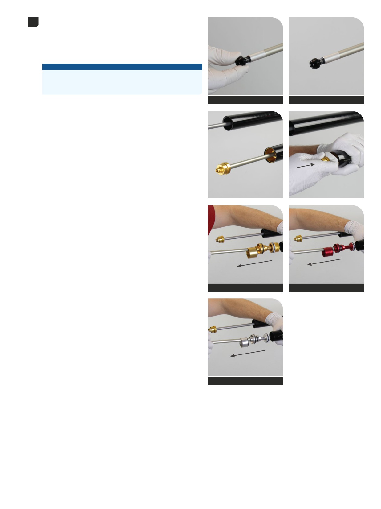
Select+, Select, Base: Thread a bottom bolt onto the shaft for added
4
grip.
Push the shaft half way into the upper tube, then quickly and firmly pull
the shaft out to dislodge the sealhead.
Remove the air spring assembly and sealhead spacer from the upper
tube.
NOTICE
Do not scratch the inside of the upper tube. Scratches can cause air
to leak. Replace the crown steerer upper tube assembly if a scratch
is visible.
Select+, Select, Base
Select+, Select, Base
ZEB
Lyrik
Pike
Air Spring Removal
42
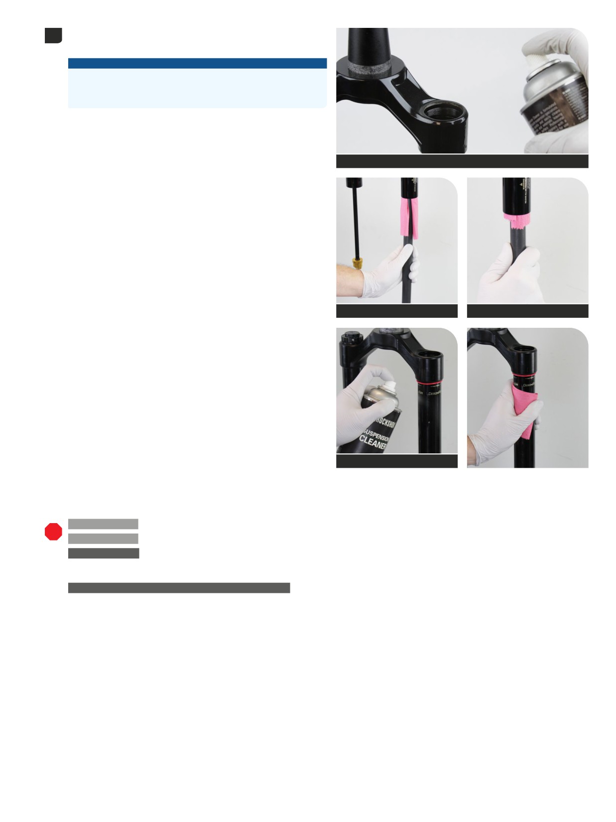
Clean the inside and outside of the upper tube.
5
Inspect the inside and outside of the upper tube for damage.
NOTICE
Scratches on the inside surface of the upper tube can cause air to
leak. Replace the crown steerer upper tube assembly if a scratch is
visible.
RockShox Suspension Cleaner
Dowel
Dowel
RockShox Suspension Cleaner
200 Hour Service
Ultimate - ButterCups Removal:
Continue with
ButterCups Removal - Air Spring Shaft - Ultimate.
200 Hour Service
Select+, Select, Base - Spring Service:
Continue with
DebonAir+ Air Spring Service.
TRAVEL CHANGE
Ultimate, Select+, Select, Base: For DebonAir+ air spring travel change, proceed to the appropriate section listed below.
Ultimate: Proceed to ButterCups Removal - Ultimate.
Select+, Select, Base: Proceed to DebonAir+ Air Spring Travel Change (optional).
UPGRADE - DEBONAIR+ AIR SPRING WITH BUTTERCUPS
Select+, Select, Base: For DebonAir+ with ButterCups air spring replacement,
proceed to Air Spring Installation.
Air Spring Removal
43
200 Hour Service
ButterCups Removal
- DebonAir+
- Ultimate
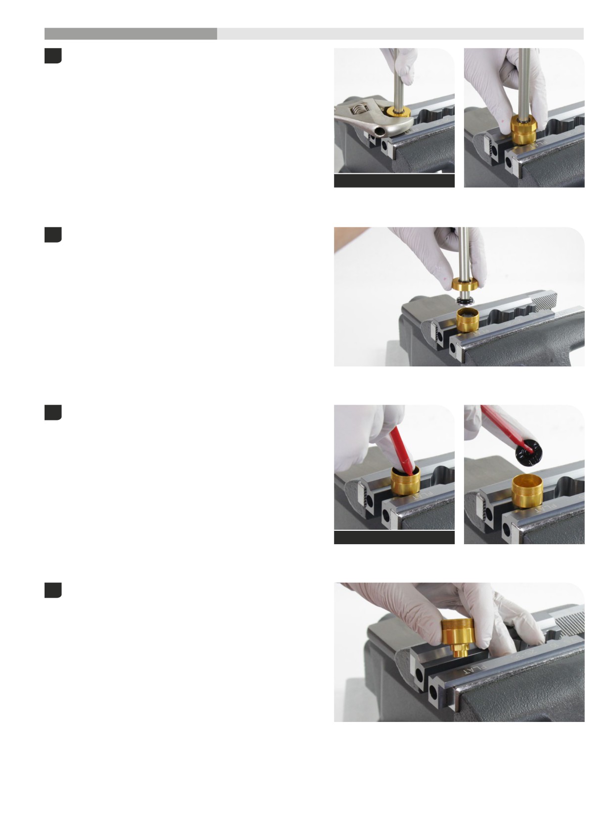
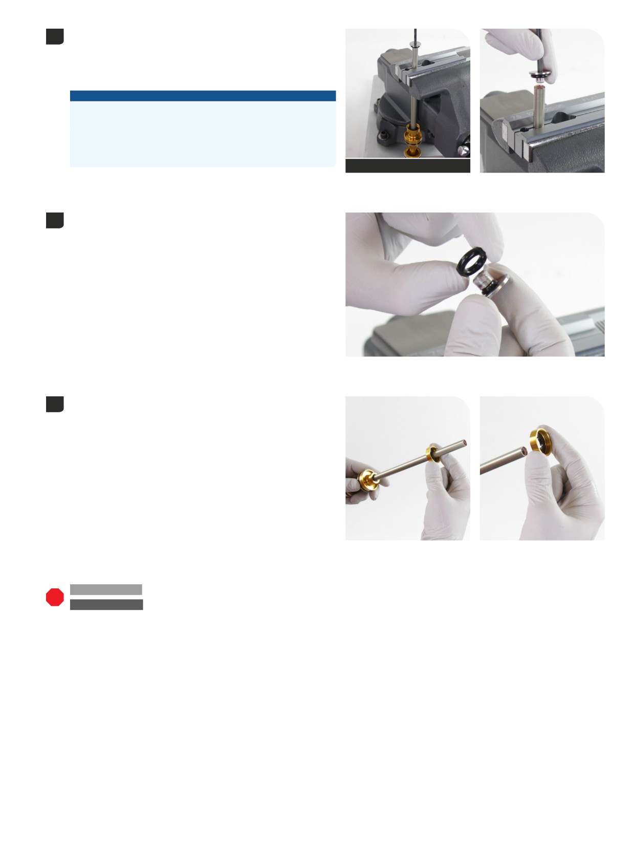
Clamp the lower ButterCups housing into a vise with Reverb Vise
1
Blocks on the wrench flats, with the air spring oriented upward.
Hold the air spring shaft for support and unthread the upper
ButterCups housing (25 mm) from the lower ButterCups housing.
Adjustable or 25 mm open end wrench
Remove the air spring assembly from the lower ButterCups housing
2
and set it aside.
Remove the ButterCups bumper from the lower ButterCups housing
3
and discard it.
Pick (non-metallic)
Remove the lower ButterCups housing from the vise. Clean the lower
4
ButterCups housing.
44
ButterCups Removal - DebonAir+ - Ultimate
Clamp the air spring shaft, 12 mm - 15 mm below the end of the shaft,
5
into the 10 mm slot of the Reverb Vise Blocks or RockShox Rear Shock
Vise Block with the air piston oriented downward.
Clamp the air spring shaft only tight enough so it does not spin when
the ButterCups shaft end plate is removed.
NOTICE
Do not scratch the air spring shaft. Scratches can cause air to leak.
Replace the air spring assembly if a scratch is visible.
Do not clamp the air spring shaft in the middle of the shaft. Clamping
force will damage the air spring shaft. If the air spring shaft is
damaged, the air spring assembly must be replaced.
T25
Reverb Vise Blocks (10 mm)
Unthread and remove the ButterCups shaft end plate from the air
spring shaft.
Remove the ButterCups shaft end plate o-ring (large) and discard it.
6
The small o-ring does not need to be removed or replaced.
Remove the air spring shaft from the vise and vise blocks.
7
Remove the upper ButterCups housing and bushing assembly from the
air spring shaft and set it aside.
200 Hour Service
Ultimate, Select+, Select, Base:
Continue with DebonAir+ Air Spring Service.
TRAVEL CHANGE
Ultimate: Continue with DebonAir+ Air Spring Travel Change (optional).
45
ButterCups Removal - DebonAir+ - Ultimate
DebonAir+ Air Spring Travel Change
(optional)
Maximum fork travel can be changed by replacing the stock air spring shaft/piston assembly with a shorter or longer air spring shaft/piston assembly.
If maximum travel is increased or reduced, a longer or shorter air spring shaft/piston assembly must be installed. For example, to change travel on a
fork with a maximum of 140 mm of travel to a maximum of 160 mm of travel, a 160 mm air spring shaft/piston assembly must be installed.
Travel Change - Select+, Select, Base: The air spring shaft insert must be removed from the original air spring shaft and installed into the longer or
shorter air spring shaft.
Travel Change - Utimate: The ButterCups assembly must be removed from the original air spring shaft/piston assembly and installed into the longer
or shorter travel change replacement air spring shaft/piston assembly. Continue to step 2 below.
It may also be necessary to add or remove Bottomless Tokens if travel is changed. Refer to Air Spring Travel Change and Bottomless Tokens for
details.
Refer to the RockShox Spare Parts Catalog at www.sram.com/service for available air spring travel change and ButterCups damper and air spring
Upgrade kits. For part ordering information, please contact your local SRAM distributor or dealer.
Select+, Select, Base only: To change travel, the air spring shaft insert
1
must be removed.
Clamp the air spring shaft, 12 mm - 15 mm below the end of the shaft,
into the 10 mm slot of the Reverb Vise Blocks or RockShox Rear Shock
Vise Block with the air piston oriented downward.
Clamp the air spring shaft only tight enough so it does not spin when
the air spring shaft insert is removed.
Unthread and remove the air spring shaft insert from the air spring
shaft and set it aside. Remove the air spring shaft from the vise.
Remove the o-ring and discard it. Apply grease to a new o-ring and
install it.
5 mm
Reverb Vise Blocks (10 mm)
NOTICE
Do not scratch the air spring shaft. Scratches can cause air to leak.
Replace the air spring assembly if a scratch is visible.
Do not clamp the air spring shaft in the middle of the shaft. Clamping
force will damage the air spring shaft. If the air spring shaft is
damaged, the air spring assembly must be replaced.
TRAVEL CHANGE: The air spring shaft insert will be installed into the
new longer or shorter air spring shaft. Proceed to step 2.
Remove the air sealhead assembly and top out bumper from the air
2
spring shaft.
Clean the top out bumper.
Set the sealhead assembly aside.
If the fork requires service, discard the sealhead assembly and install
a new sealhead assembly in Step 7 (200 Hour Service Kit required). Go
to Air Spring Service for complete service procedures.
Ultimate: Proceed to step 4.
Pick (non-metallic)
46
DebonAir+ Air Spring Travel Change (optional)
Select+, Select, Base only: Clamp the new (longer or shorter) air spring
3
shaft into the 10 mm slot of the Reverb Vise Blocks or RockShox Rear
Shock Vise Block with the air piston oriented downward.
Clamp the air spring shaft only tight enough so it does not spin when
the air spring shaft insert is removed.
Apply Threadlocker Loctite 2760 (red) or equivalent to 2 to 3 threads
on the air spring shaft insert.
Install the insert into the shaft and tighten it.
Remove the air spring shaft from the vise.
NOTICE
Do not scratch the air spring shaft. Scratches can cause air to leak.
Threadlocker Loctite 2760 - Red
5 mm
4 N·m (32 in-lb)
Replace the air spring assembly if a scratch is visible.
Apply grease to the quad ring seal and air piston.
4
SRAM Butter Grease
Apply a liberal amount of grease to the air spring shaft.
5
SRAM Butter Grease
Apply a thin layer of grease to the top out bumper and install it onto the
6
air spring shaft.
SRAM Butter Grease
47
DebonAir+ Air Spring Travel Change (optional)
Apply grease to the inner and outer seals on the sealhead.
7
SRAM Butter Grease
SRAM Butter Grease
SRAM Butter Grease
Install the sealhead assembly onto the air shaft, flat side first.
8
DebonAir+ Air Spring Travel Change (optional)
48
Remove the grease from the shaft (Ultimate) or shaft insert (Select+,
9
Select, Base) inner threads.
Ultimate
Select+, Select, Base
TRAVEL CHANGE
Select+, Select, Base: For travel change only, proceed to Air Spring Installation.
TRAVEL CHANGE
Ultimate: For travel change only, proceed to ButterCups Installation.
49
DebonAir+ Air Spring Travel Change (optional)
DebonAir+ Bottomless Tokens
Bottomless Tokens can be added to, or removed from the DebonAir+ top cap to fine-tune the bottom-out feel and spring curve. Use the table below to
help determine the number of Bottomless Tokens that can be used with each maximum fork travel option. If fork travel is changed from stock, it may
be necessary to add or remove Bottomless Tokens.
Refer to the RockShox Suspension Tuning and Setup Guide for more details. Refer to the RockShox Spare Parts Catalog at www.sram.com/service for
available air spring and Bottomless Token kits. For part ordering information, please contact your local SRAM distributor or dealer.
ZEB - 27.5" Boost & 29" Boost
Fork Travel
Bottomless Tokens (grey)
Bottomless Tokens (grey)
(mm)
Factory Installed
Maximum
190
0
4
180
0
4
170
1
4
160
1
5
150
2
5
Lyrik - 27.5" Boost & 29" Boost
Fork Travel
Bottomless Tokens (grey)
Bottomless Tokens (grey)
(mm)
Factory Installed
Maximum
160
0
5
150
0
5
140
1
5
Pike - 27.5" Boost & 29" Boost
Fork Travel
Bottomless Tokens (grey)
Bottomless Tokens (grey)
(mm)
Factory Installed
Maximum
140
0
5
130
0
6
120
1
6
DebonAir+ Bottomless Tokens Installation
(optional)
Bottomless Tokens reduce air volume in your fork and create greater ramp at the end of the fork travel. Add or remove Tokens to tune your fork's
bottomless feel. Do not install more than the maximum number of Bottomless Tokens for your fork.
Install Bottomless Token(s) onto the air spring top cap, as desired.
Thread a Bottomless Token into another Bottomless Token, and/or into
the bottom of the top cap, and tighten.
8 mm
4 N∙m (35 in-lb)
Top cap / Cassette tool
DebonAir+ Bottomless Tokens
50
200 Hour Service
Air Spring Service
A ZEB Ultimate air spring assembly is pictured in this section. Procedures are the same for ZEB, Lyrik, and Pike unless otherwise picture or described.
Remove the air sealhead assembly and top out bumper from the air
1
spring shaft.
Discard the sealhead assembly.
Clean the top out bumper.
Clean and inspect the air spring shaft for damage.
NOTICE
Scratches can cause air to leak. Replace the air spring assembly if a
scratch is visible.
Pick (non-metallic)
Air Spring Service
51
Remove the glide ring (upper), quad ring, and backup ring (lower) from
2
the air piston and discard them.
NOTICE
Do not scratch the air piston. Scratches will cause air to leak.
Replace the air spring assembly if a scratch is visible.
Pick
Clean the air piston.
3
Air Spring Service
52
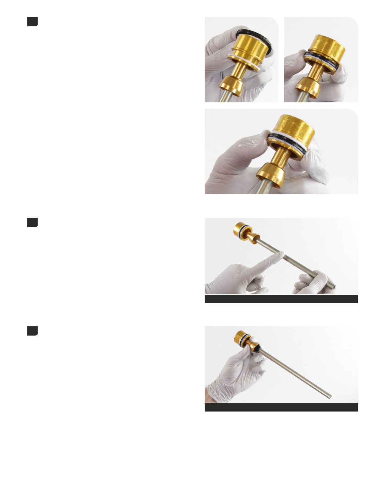
Install a new backup ring (thin, lower) onto the air piston.
4
Apply grease to the new quad ring seal and install it onto the air piston
above the backup ring.
Install a new glide ring (thick, upper) tapered end upward, above the
quad ring seal.
Apply a liberal amount of grease to the air spring shaft.
5
SRAM Butter Grease
Apply a thin layer of grease to the new top out bumper and install it
6
onto the air spring shaft.
SRAM Butter Grease
Air Spring Service
53
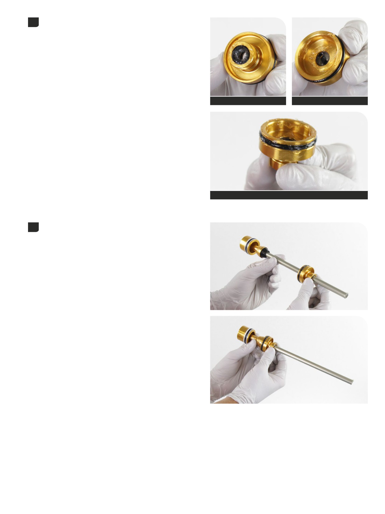
Apply grease to the inner and outer seals on the new sealhead.
7
SRAM Butter Grease
SRAM Butter Grease
SRAM Butter Grease
Install the new sealhead assembly onto the air shaft, flat side first.
8
Air Spring Service
54
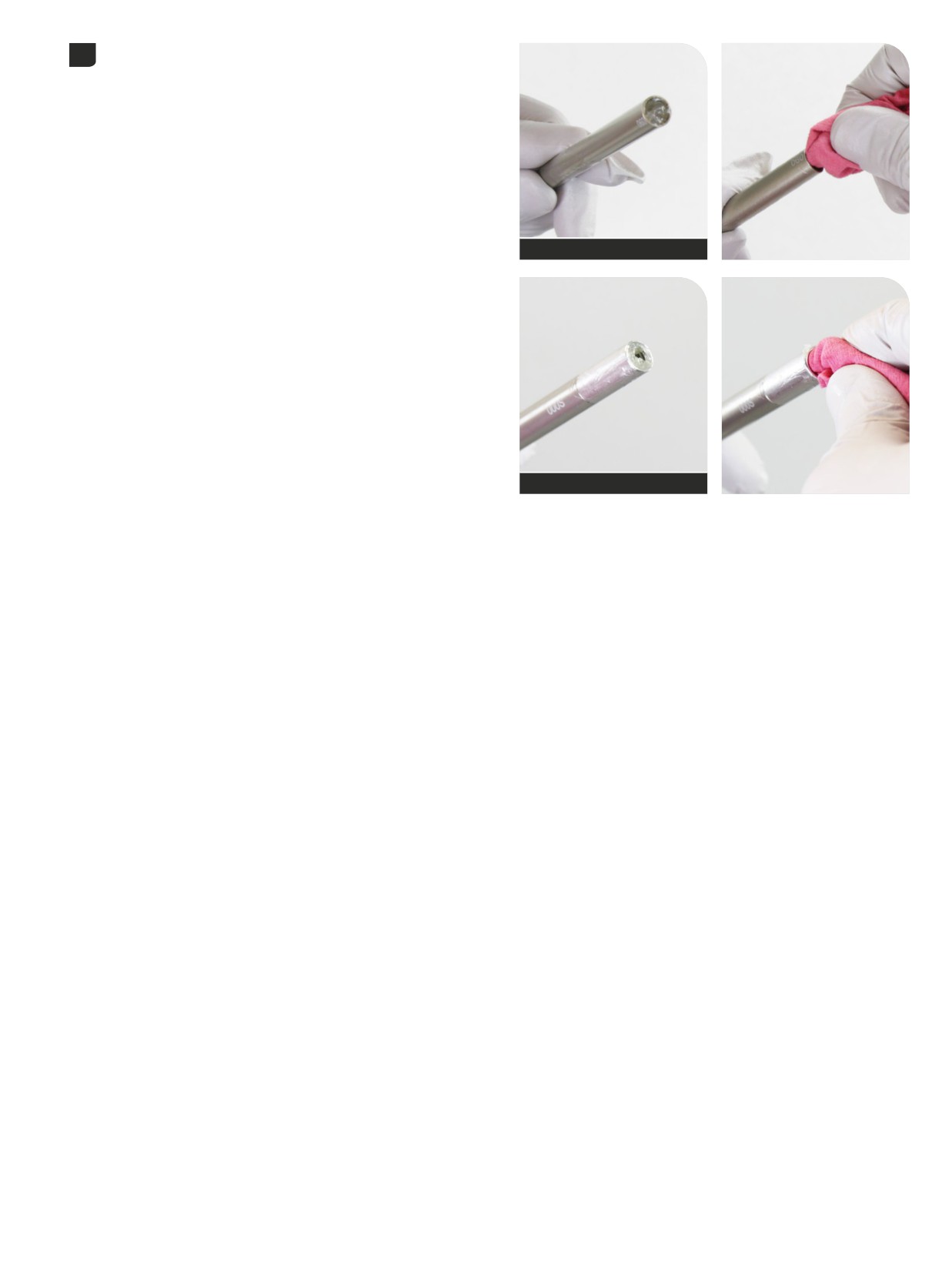
Remove the grease from the inner shaft threads.
9
Ultimate
Select+, Select, Base
Air Spring Service
55
200 Hour Service
ButterCups Installation
- DebonAir+
- Ultimate
Refer to the RockShox Spare Parts Catalog at www.sram.com/service for available DebonAir+ Air Spring with ButterCups upgrade kits. For part
ordering information, please contact your local SRAM distributor or dealer.
The DebonAir+ air spring shaft ButterCups assembly is NOT compatible with Dual Position Air. Do not install a DebonAir+ air spring shaft ButterCups
assembly onto a Dual Position Air air spring shaft.
The DebonAir+ air spring shaft ButterCups assembly is NOT compatible with a DebonAir+ air spring shaft with a shaft insert installed (Select+, Select,
Base). Do not install a DebonAir+ air spring shaft ButterCups assembly onto a DebonAir+ air spring shaft if a shaft insert is installed. Remove the shaft
insert before installing a DebonAir+ ButterCups assembly.
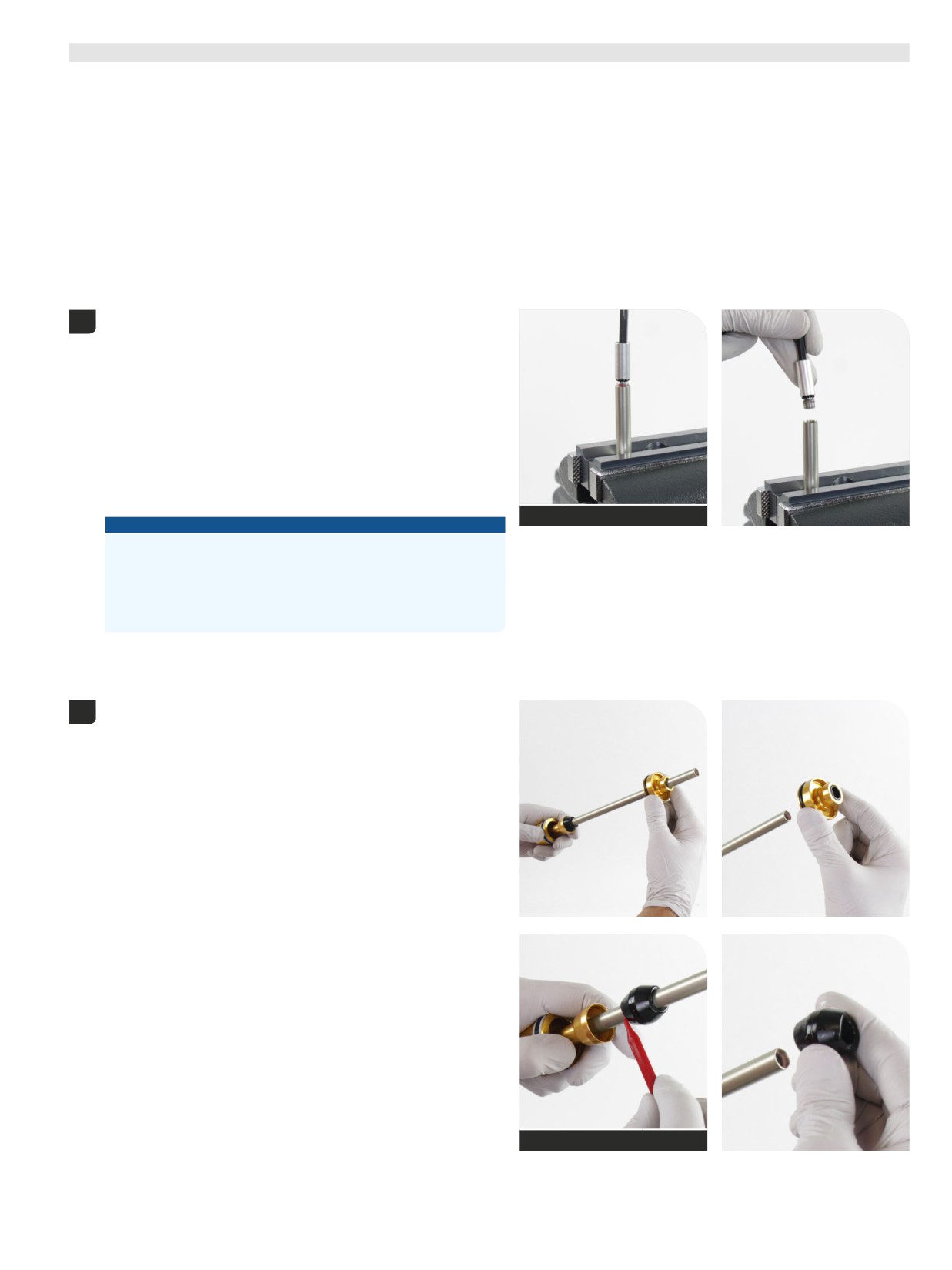
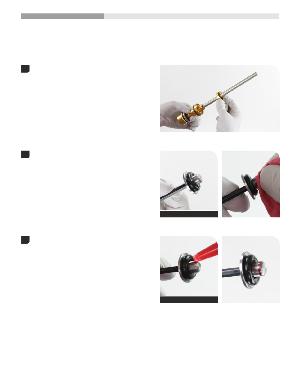
Install the ButterCups upper housing and bushing assembly onto the
1
air spring shaft.
Apply grease to a new o-ring and install it onto the ButterCups shaft
2
end plate, over the threads.
Clean all grease from the threads.
SRAM Butter Grease
Apply Loctite Threadlocker 2760 (red), or equivalent, to the first two to
3
three full threads of the ButterCups shaft end plate.
Threadlocker Loctite 2760 - Red
56
ButterCups Installation - DebonAir+ - Ultimate
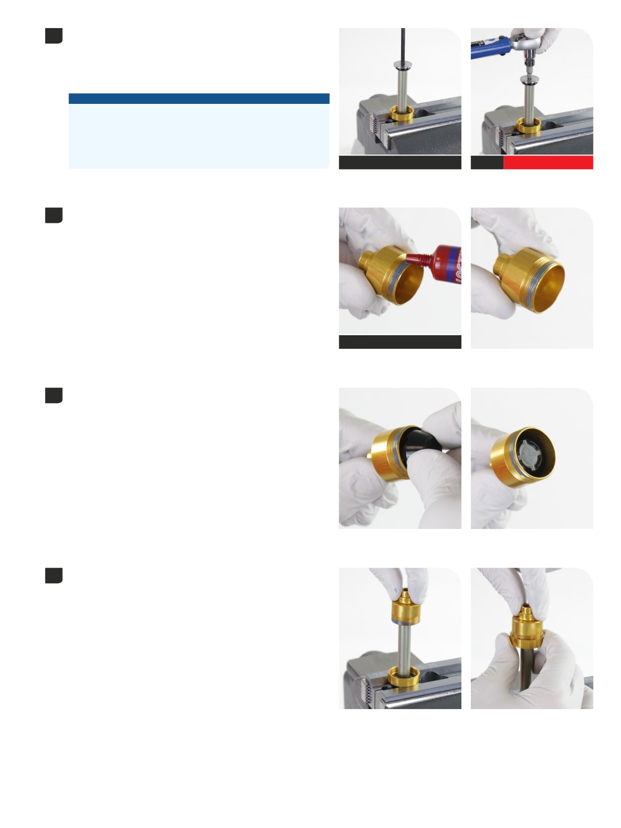
Position the upper ButterCups housing above the vise blocks.
4
Clamp the air shaft into the 10 mm slot of the Reverb Vise Blocks or
RockShox Rear Shock Vise Block.
Clamp the air shaft only tight enough so it does not spin when the
ButterCups is tightened.
NOTICE
Scratches can cause air to leak. Replace the air spring assembly if a
scratch is visible.
Do not clamp the air spring shaft in the middle of the shaft. Clamping
force will damage the air spring shaft. If the air spring shaft is
damaged, the air spring assembly must be replaced.
T25
RockShox Vise Blocks (10 mm)
T25
4 N∙m (32 in-lb)
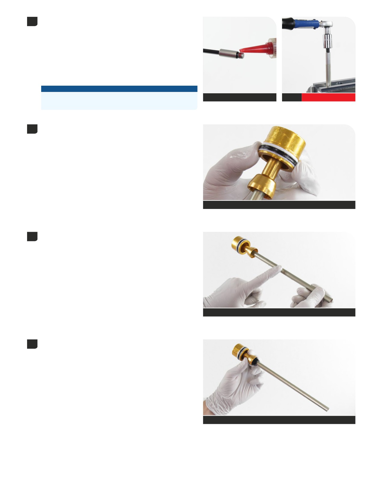
Thread the ButterCups shaft end plate into the air shaft and tighten it.
Apply Loctite Threadlocker Blue 242 (blue), or equivalent, to three full
5
outer threads on the lower ButterCups housing.
Theadlocker Loctite 242 - Blue
Install a new ButterCups bumper into the lower ButterCups housing,
6
wide end first.
Position the lower ButterCups housing and bumper onto the
7
ButterCups end plate.
Slide the upper ButterCups housing and bushing assembly up and
thread it onto the lower ButterCups housing finger tight.
ButterCups Installation - DebonAir+ - Ultimate
57
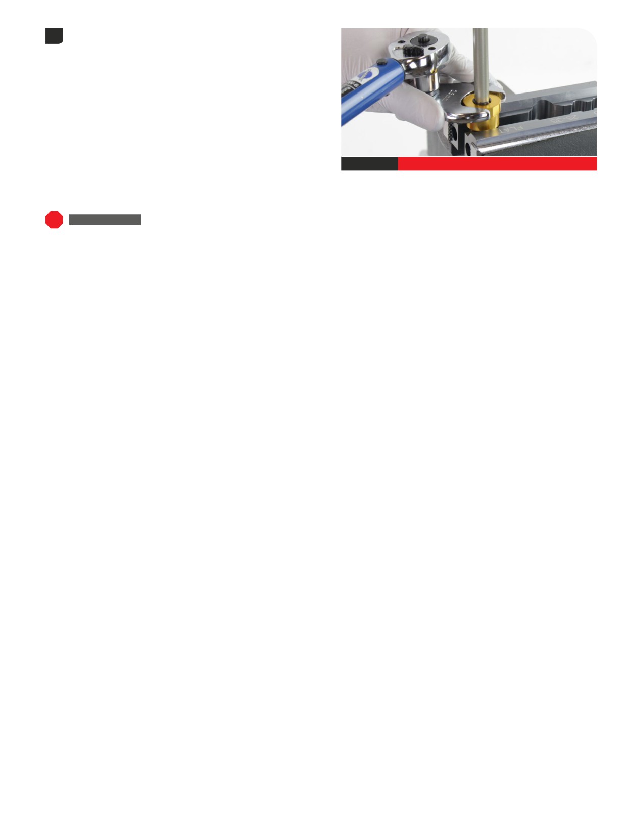
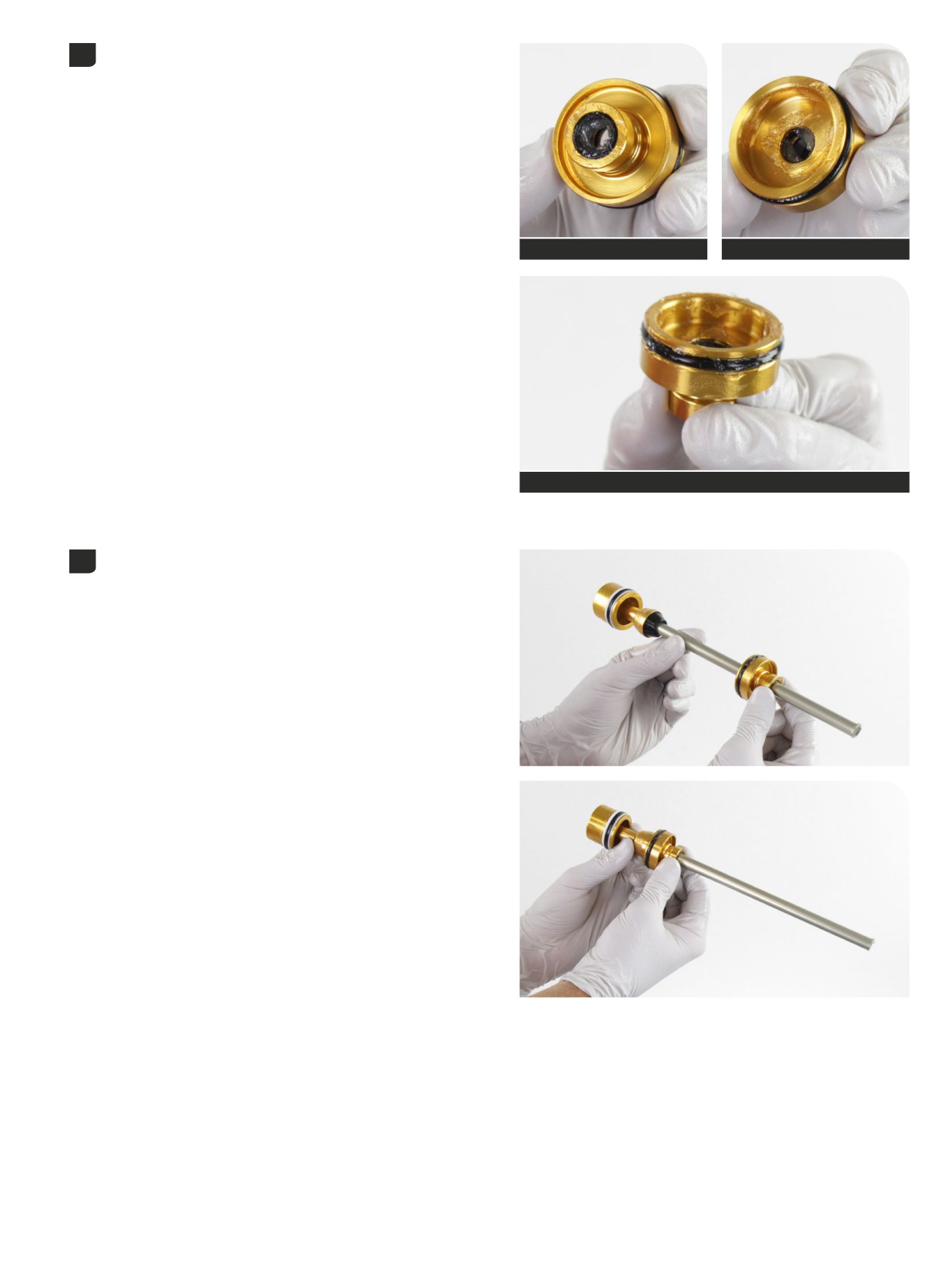
Remove the air shaft from the vise and vise blocks.
8
Clamp the lower ButterCups housing into a vise with Reverb Vise
Blocks on the wrench flats, air spring piston oriented upward.
Tighten the upper ButterCups housing onto the lower housing.
25 mm
14 N∙m (125 in-lb)
TRAVEL CHANGE
Ultimate: For travel change only, proceed to Air Spring Installation.
58
ButterCups Installation - DebonAir+ - Ultimate
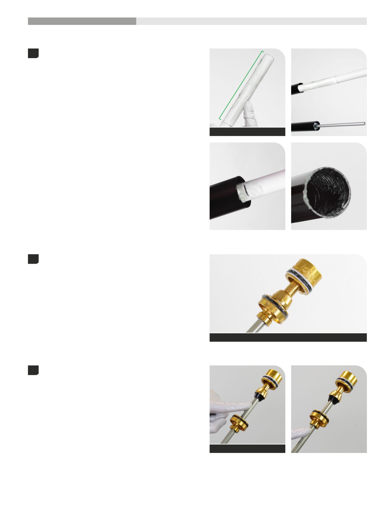
200 Hour Service
Air Spring Installation
Upgrade DebonAir+ Air Spring with ButterCups (Select+, Select, and Base): Follow the procedures below to install an optional DebonAir+ Air Spring
assembly with ButterCups Upgrade Kit.
Apply a liberal amount of SRAM Butter grease evenly around the end
1
of a clean plastic dowel, approximately 150 mm from one end. Use
the dowel to apply the grease to the inside surface of the upper tube,
approximately 150 mm into the tube.
Dowel and grease
150 mm
Apply grease to the air piston and sealhead outer o-rings.
2
SRAM Butter Grease
Upgrade only - DebonAir+ Air Spring with ButterCups: Apply grease
3
to the NEW air spring shaft above and below the sealhead. Slide the
sealhead and top out bumper up and down to spread the grease and
lubricate the seals.
SRAM Butter Grease
Air Spring Installation
59
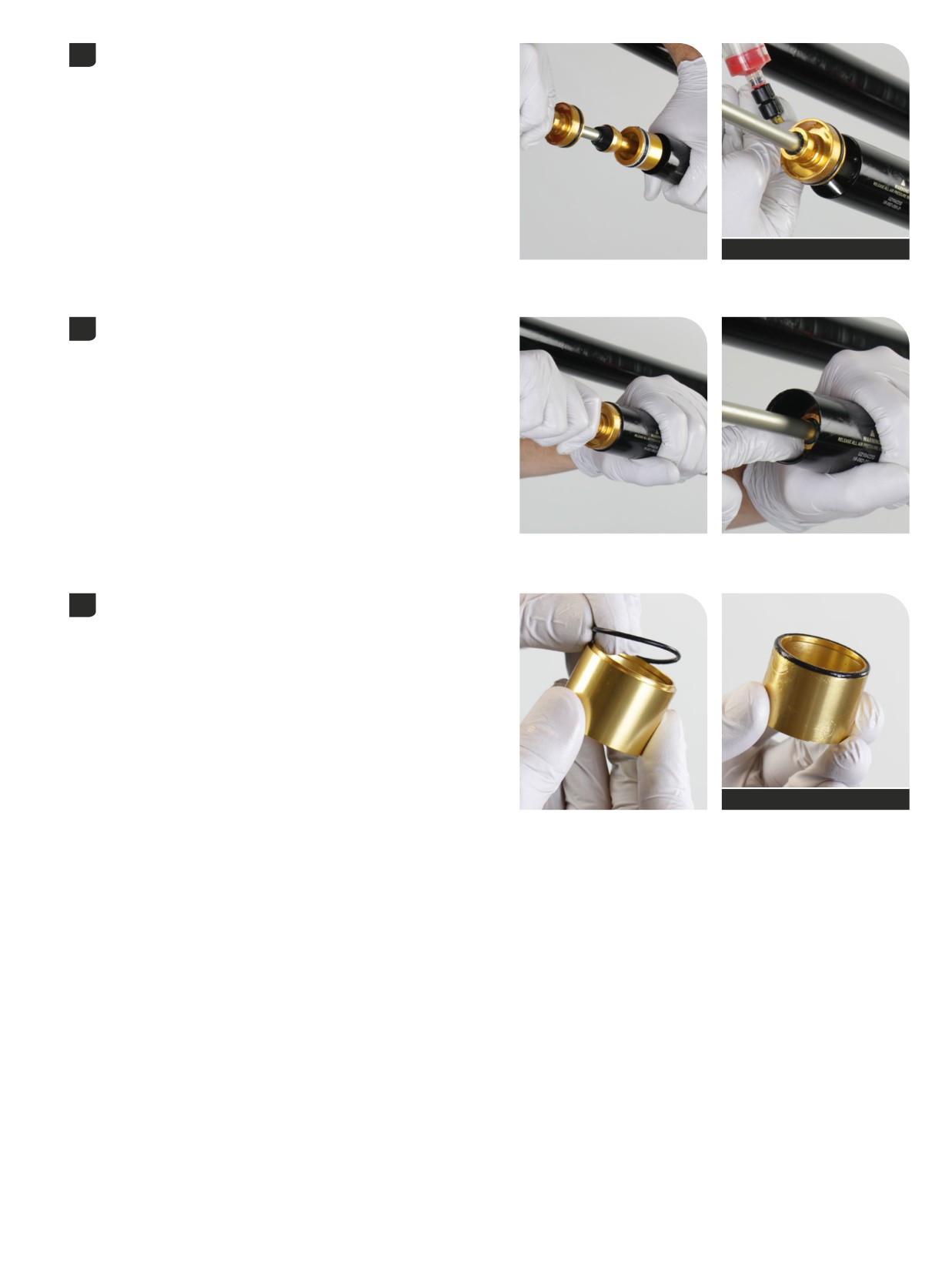
With the crown steerer upper tube assembly clamped in the bicycle
4
work stand, orient the upper tubes upward and the steerer tube
oriented downward.
Insert the air spring assembly into the upper tube. Firmly push the air
piston into the upper tube.
Inject 1 mL of Maxima PLUSH Dynamic Suspension Lube Heavy into the
upper tube, between the piston and sealhead, in the negative chamber.
1 mL
RockShox Bleed Syringe
Insert the air sealhead into the upper tube and firmly press it into the
5
upper tube until it stops.
Remove the o-ring from the spring spacer and discard it. Apply grease
6
to a new sealhead spacer o-ring and install it onto the sealhead spacer.
Upgrade only - DebonAir+ Air Spring with ButterCups: Apply grease
to the o-ring on the sealhead spacer.
SRAM Butter
Air Spring Installation
60
Insert the sealhead spacer into the upper tube, o-ring end first, and
7
seat it into the upper tube step until it stops.
Install a section of protective split plastic tube, or a shop towel, around
8
the air spring shaft to protect the shaft surface during installation.
Ultimate pictured.
NOTICE
Do not scratch the air spring shaft. Scratches can cause air to leak.
Replace the air spring assembly if a scratch is visible.
ZEB: Eyelet retaining rings have a sharper edged side and a rounder
edged side. Installing retaining rings with the sharper edged side
facing the tool will allow for easier installation and removal.
Guide the retaining ring with your finger to prevent scratching the air
shaft.
Split plastic tube
Retaining ring pliers
Place the tips of the retaining ring pliers into the eyelets of the retaining
ring, then use the pliers to push the sealhead into the upper tube while
installing the retaining ring into the groove.
Confirm the retaining ring is properly seated in the retaining ring
groove by using the retaining ring pliers to rotate the retaining ring
and sealhead back and forth a few times.
Remove the split plastic tube or shop towel from the shaft.
Air Spring Installation
61
Install a section of protective split plastic tube, or a shop towel, around
the air spring shaft to protect the shaft surface during installation.
Select+, Select, Base pictured.
NOTICE
Do not scratch the air spring shaft. Scratches can cause air to leak.
Replace the air spring assembly if a scratch is visible.
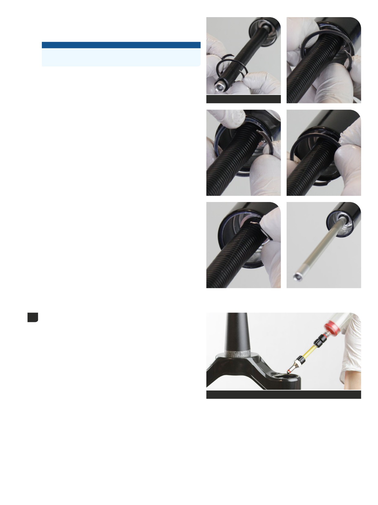
Lyrik and Pike: Lift both prong ends from the center of the ring to open
the retaining ring for installation.
Insert the inner retaining ring prong end into the upper tube retaining
ring groove.
Split plastic tube
Using your thumb, guide and push the retaining ring edge, starting
at the installed prong end, around the upper tube edge and into the
groove.
The retaining ring is installed completely when the outer prong end
snaps into the groove.
Confirm the retaining ring is properly seated completely in the
retaining ring groove.
Remove the split plastic tube or shop towel from the shaft.
Inject or pour 3 mL Maxima PLUSH Dynamic Suspension Lube Heavy
9
into the air spring upper tube.
3 mL
RockShox Bleed Syringe
Air Spring Installation
62
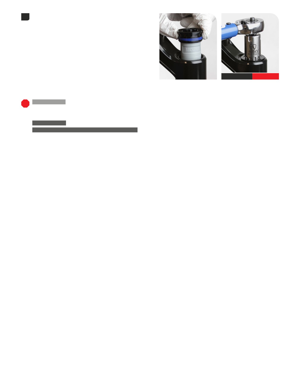
Install the air spring top cap into the upper tube and tighten it. Press
10
down firmly when tightening the top cap.
Top cap /
28 N∙m (250 in-lb)
Cassette tool
200 Hour Service
To continue with damper service, proceed to the appropriate damper service section.
Ultimate, Select+ - Charger 3 RC2 Damper: Damper Service - Charger 3 RC2
Select - Charger RC Damper: Damper Service - Charger RC
Base - Rush RC Damper: Damper Service - Rush RC
TRAVEL CHANGE
Ultimate, Select+, Select, Base: To complete travel change only, proceed to Lower Leg Installation.
UPGRADE - DEBONAIR+ AIR SPRING WITH BUTTERCUPS
Select+, Select, Base: To complete DebonAir+ air spring upgrade installation,
proceed to Lower Leg Installation.
Air Spring Installation
63
Dual Position Air
(DPA)
- ZEB
- Air Spring Service
ButterCups are NOT compatible with Dual Postion Air. Do NOT install a ButterCups assembly onto a Dual Position Air spring shaft.
200 Hour Service
Air Spring Removal
⚠WARNING- EYE HAZARD
Verify all pressure is removed from the fork before proceeding. Depress the Schrader valve again to remove any remaining air pressure. Failure to
do so can result in injury and/or damage to the fork.
NOTICE
Inspect each part for scratches. Do not scratch any sealing surfaces when
servicing your suspension. Scratches can cause leaks.
When replacing seals and o-rings, use your fingers or a pick to remove the
seal or o-ring. Spray RockShox Suspension Cleaner or isopropyl alcohol
onto each part and clean with a clean lint-free shop towel.
Apply SRAM Butter Grease to the new seals and o-rings.
SRAM Butter Grease
Remove the travel adjuster knob retaining nut.
1
10 mm
Remove the travel adjuster knob.
Remove the air spring top cap. Press down firmly when loosening the
2
top cap.
NOTICE
The fork top caps are tightened to a high torque value. Ensure the
fork is held securely in the bicycle stand. To avoid damage to the
top cap, press the top cap / cassette tool squarely and firmly down
when loosening. Use a socket wrench with a long handle for extra
leverage.
Clean the upper tube threads.
24 mm
64
Dual Position Air (DPA) - ZEB - Air Spring Service
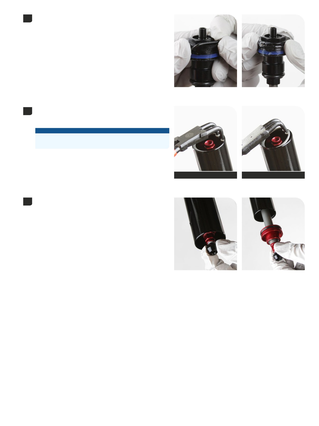
Remove the top cap o-ring and discard it. Apply grease to a new o-ring
3
and install it.
Push the air shaft into the upper tube to prevent it from getting
4
scratched while removing the retaining ring.
Remove the retaining ring.
NOTICE
Do not scratch the air spring shaft. Scratches can cause air to leak.
Replace the air spring assembly if a scratch is visible.
Retaining ring pliers
Retaining ring pliers
Thread the shaft bolt into the end of the air spring shaft for added grip.
5
With the shaft pushed half way into the upper tube, quickly and firmly
pull the shaft out to remove the sealhead and air spring assemblies
from the upper tube.
Remove the shaft bolt from the air spring shaft.
Air Spring Removal
65
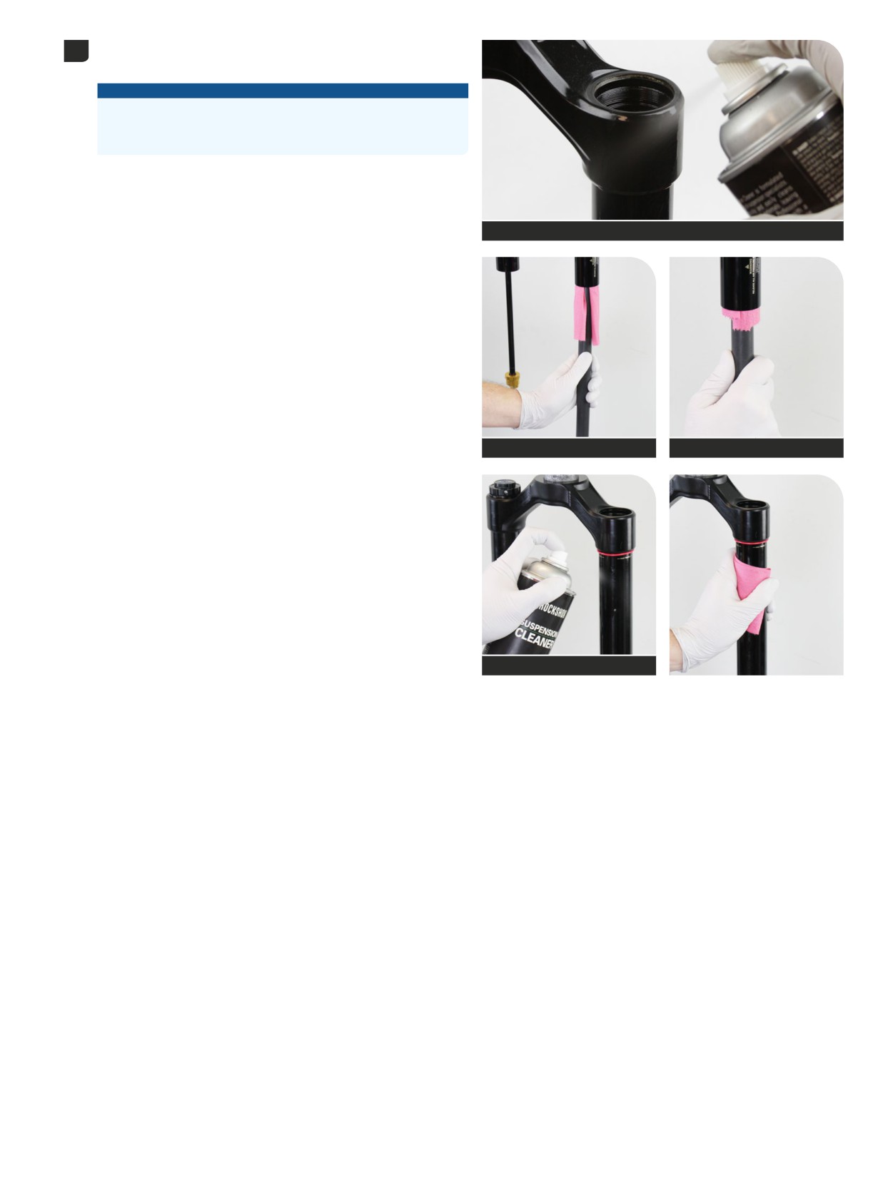
Clean the inside and outside of the upper tube.
6
Inspect the inside and outside of the upper tube for damage.
NOTICE
Scratches on the inside surface of the upper tube can cause air to
leak. Replace the crown steerer upper tube assembly if a scratch is
visible.
RockShox Suspension Cleaner
Dowel
Dowel
RockShox Suspension Cleaner
Air Spring Removal
66
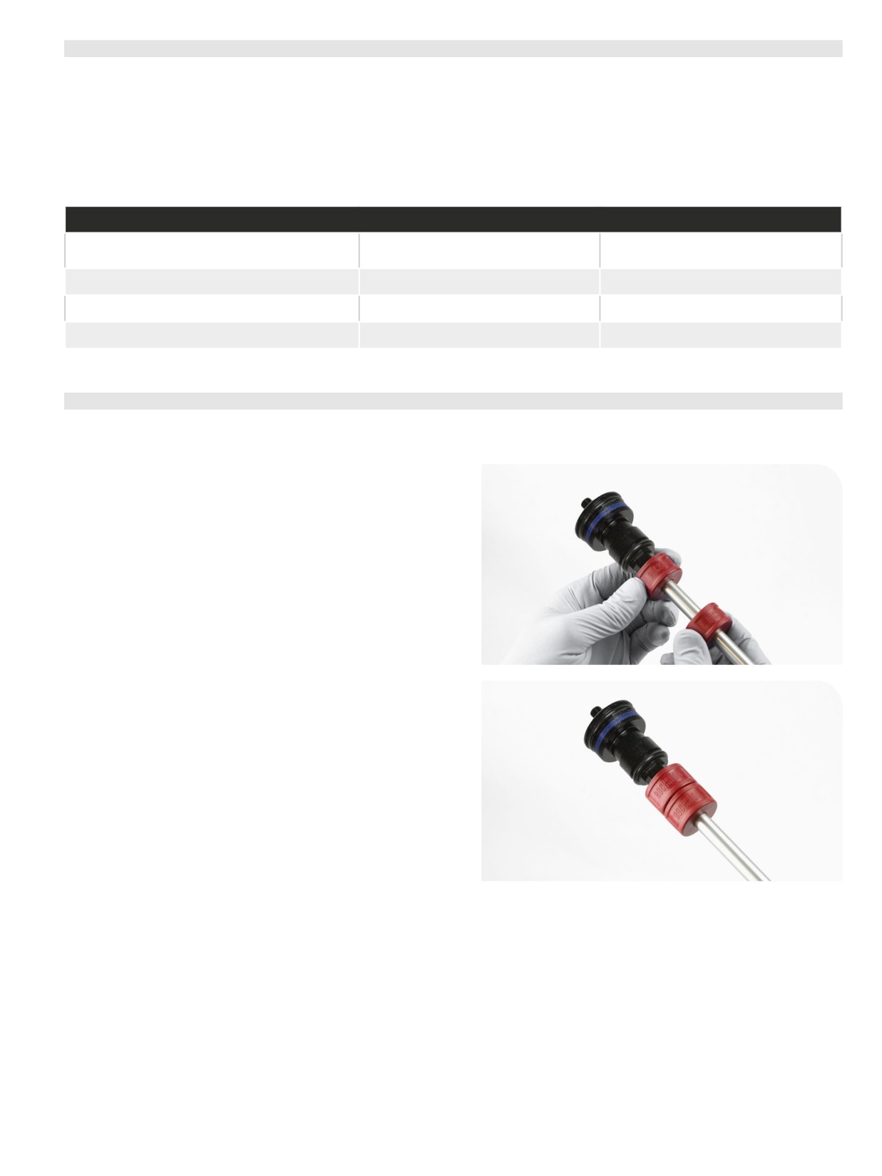
DPA Air Spring Travel and Bottomless Tokens
To increase or decrease the travel in your RockShox ZEB fork, the air spring must be replaced with the appropriate length air spring shaft assembly.
For example, to change a ZEB with a maximum of 160 mm of travel to a maximum of 180 mm of travel, a 180 mm air spring shaft assembly must be
installed.
Bottomless Tokens can be added to, or removed from, the Dual Position Air (DPA) air spring assembly to fine-tune the bottom-out feel and spring
curve. Use the chart below to help determine the number of Bottomless Tokens that can be used with each maximum fork travel option. If fork travel is
changed from stock, it may be necessary to add or remove Bottomless Tokens.
Refer to the RockShox Spare Parts Catalog at www.sram.com/service for available air spring and Bottomless Token kits. For part ordering information,
please contact your local SRAM distributor or dealer.
ZEB - 27.5" Boost & 29" Boost
Fork Travel
Bottomless Tokens (red)
Bottomless Tokens (red)
(mm)
Factory Installed
Maximum
180
0
4
170
1
4
160
2
5
DPA Bottomless Tokens Installation
(optional)
Bottomless Tokens reduce air volume in your fork and create greater ramp at the end of the fork travel. Add Tokens to tune your fork's bottomless
feel. Do not install more than the maximum number of Bottomless Tokens for your fork.
Install Bottomless Token(s) onto the DPA air spring shaft, as desired.
67
DPA Air Spring Travel and Bottomless Tokens
DPA Air Spring Travel Change and Bottomless Tokens
(optional)
It is optional to change maximum fork travel by replacing the stock air spring shaft assembly with a shorter or longer air spring shaft assembly. If
maximum travel is increased or reduced, use the new complete air spring shaft assembly in the following installation steps. It may also be necessary
to add or remove Bottomless Tokens. Refer to Air Spring Travel Change and Bottomless Tokens for details.
Refer to the RockShox Spare Parts Catalog available at www.sram.com/service for the required spare part kits.
For part ordering information, please contact your local SRAM distributor or dealer.
200 Hour Service
Air Spring Service
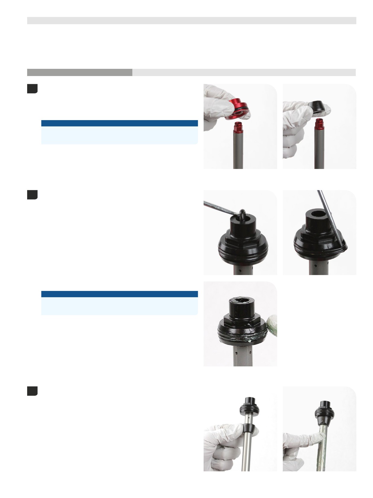
Remove the sealhead and top out bumper from the air spring shaft.
1
Discard the sealhead.
Clean and inspect the shaft for damage.
Clean the top out bumper.
NOTICE
Do not scratch the air spring shaft. Scratches can cause air to leak.
Replace the air spring assembly if a scratch is visible.
Remove the inner and outer air piston o-rings and discard them. Clean
2
the air piston.
Apply grease to new o-rings and install them.
NOTICE
Do not scratch the air piston. Scratches can cause air to leak.
Replace the air spring assembly if a scratch is visible.
Install the top out bumper onto the shaft.
3
Apply a liberal amount of grease to the air spring shaft.
DPA Air Spring Travel Change and Bottomless Tokens (optional)
68
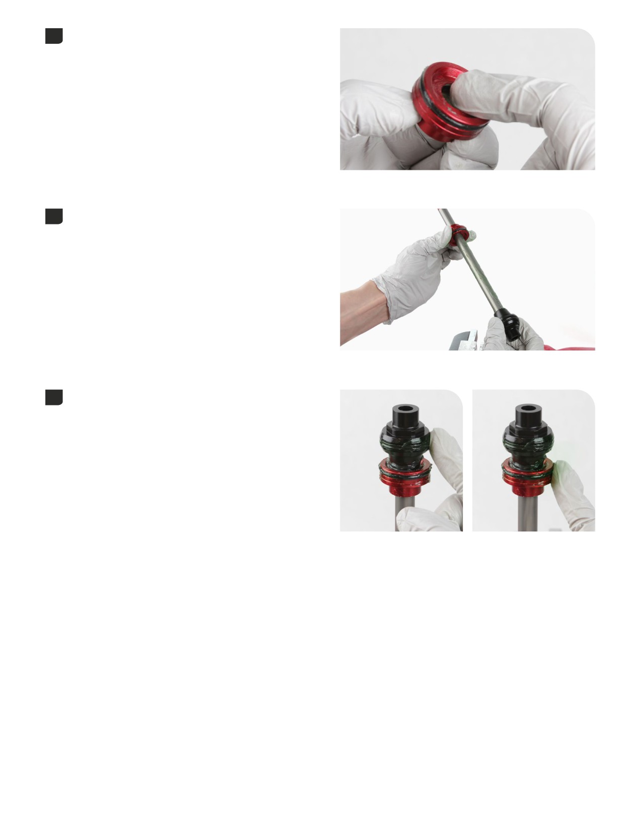
Apply grease to the new seal o-ring and wiper seal.
4
Install the retaining washer/backup ring, a new wave spring, and the
5
new sealhead assembly, in that order, onto the air shaft.
Apply grease to the air piston and sealhead outer o-ring/seals.
6
Air Spring Service
69
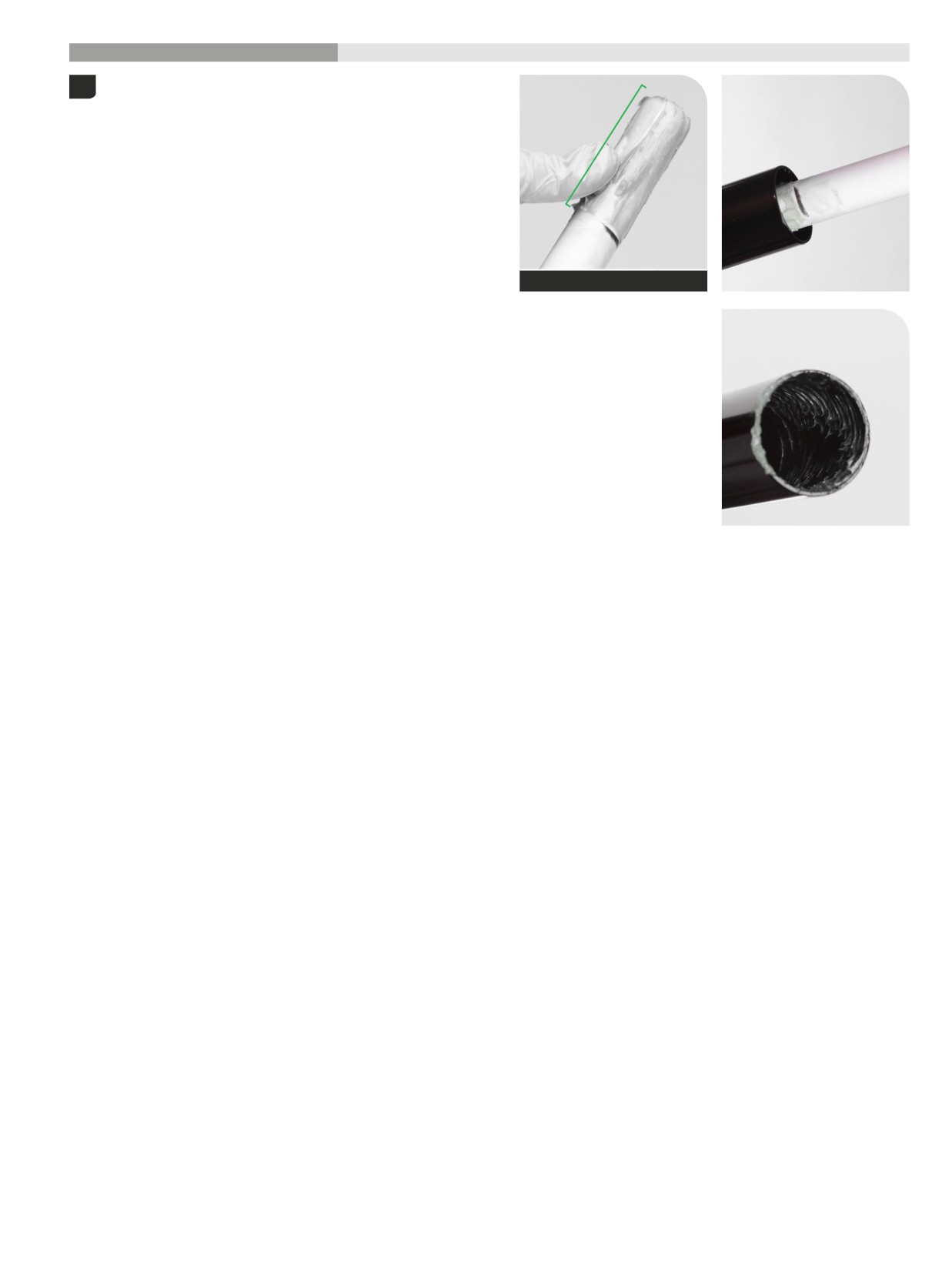
200 Hour Service
Air Spring Installation
Apply a liberal amount of SRAM Butter grease evenly around the end
1
of a clean plastic dowel, approximately 60 mm from one end. Use the
dowel to apply the grease to the inside surface of the upper tube,
approximately 60 mm into the tube.
Dowel and grease
60 mm
Air Spring Installation
70
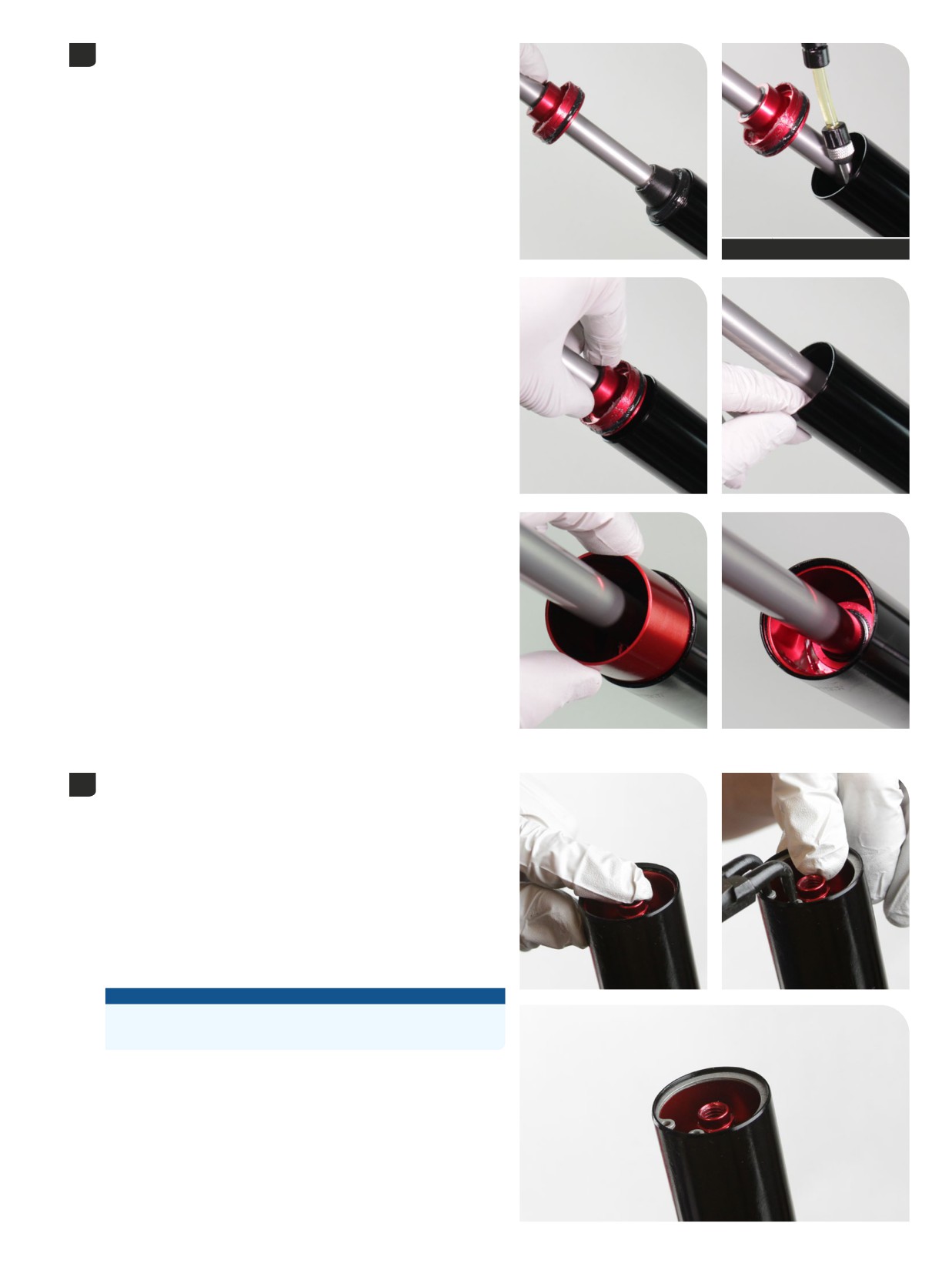
Insert the air spring piston into the upper tube. Firmly push the air
2
spring piston into the upper tube.
Inject 1 mL of Maxima PLUSH Dynamic Suspension Lube Heavy into the
upper tube, between the piston and sealhead, in the negative chamber.
Insert the sealhead into the upper tube. Firmly press the sealhead into
the upper tube until it stops.
Insert the sealhead spacer into the upper tube. Firmly press the
sealhead spacer into the upper tube until it stops.
1 mL
RockShox Bleed Syringe
Retaining rings have a sharper-edged side and a rounder edged side.
3
Installing retaining rings with the sharper-edged side facing the tool
will allow for easier installation and removal.
Push the air shaft into the upper tube to prevent it from getting
scratched while installing the retaining ring.
Place the tips of the retaining ring pliers into the eyelets of the retaining
ring, then use the pliers to push the sealhead into the upper tube while
installing the retaining ring into the groove.
Confirm the retaining ring is properly seated in the retaining ring
groove by using the retaining ring pliers to rotate the retaining ring
and sealhead back and forth a few times, then firmly pull down on
the air shaft.
NOTICE
Do not scratch the air spring shaft. Scratches can cause air to leak.
Replace the air spring assembly if a scratch is visible.
Air Spring Installation
71
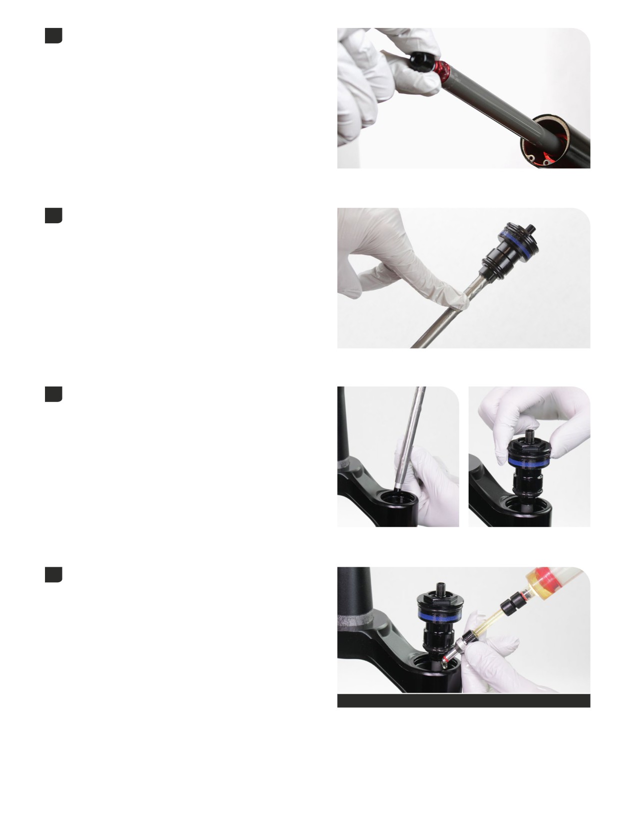
Thread a bottom bolt into the shaft 2 to 3 turns and pull the lower air
4
shaft out to approximately half way.
Remove the bolt.
Apply a liberal amount of grease to the top cap upper air spring shaft.
5
Install the upper air spring shaft into the upper tube and into the air
6
piston and lower air spring shaft.
The upper air spring shaft must be installed into the air piston and
lower air spring shaft before oil is added to the positive air chamber.
Inject or pour 3 mL Maxima PLUSH Dynamic Suspension Lube Heavy
7
into the air spring upper tube.
3 mL
RockShox Bleed Syringe
Air Spring Installation
72
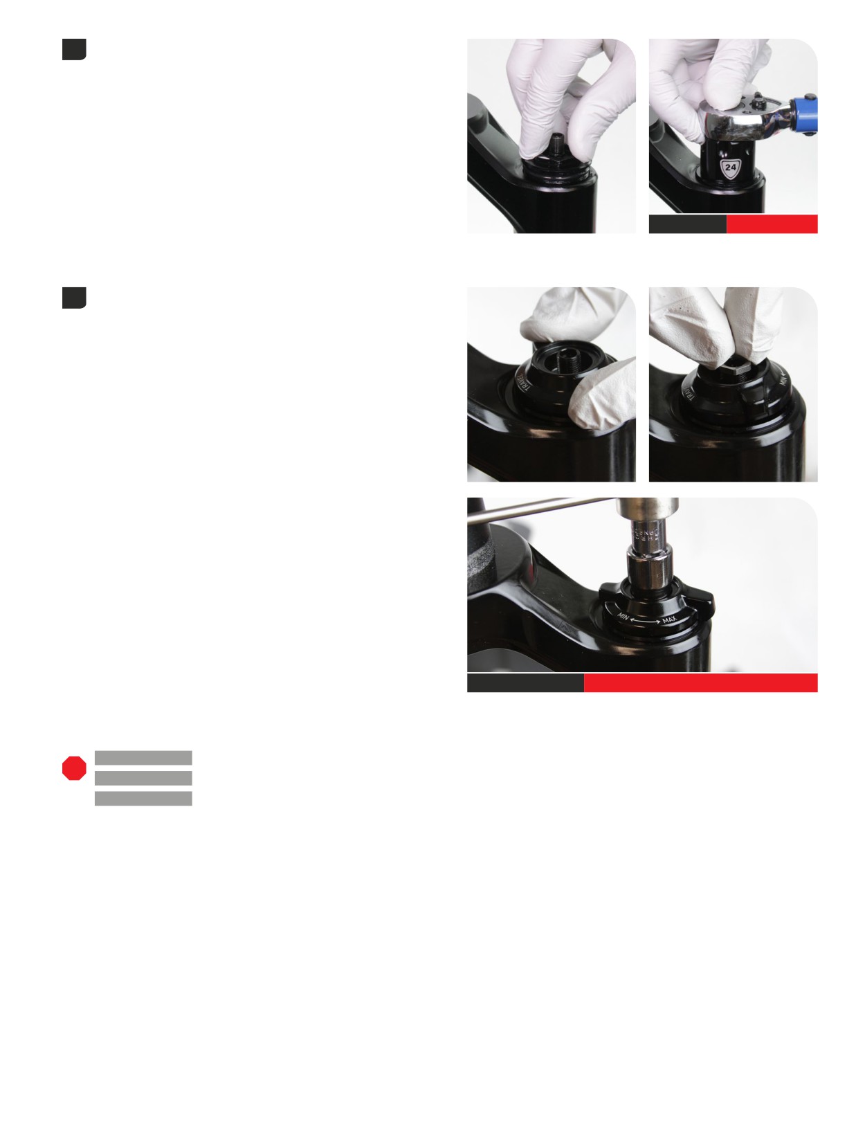
Thread the top cap assembly into the upper tube and tighten it. Press
8
down firmly when tightening the top cap.
24 mm
28 N·m (250 in-lb)
Place the adjuster knob onto the top cap with the long tab near the
9
back of the crown. Turn the adjuster knob counterclockwise until it
engages the first detent space.
Thread the knob retaining nut onto the threaded air valve body and
tighten the knob retaining nut.
10 mm
2 N·m (18 in-lb)
200 Hour Service
Ultimate, Select+ - Charger 3 RC2 Damper:
Continue with
Damper Service - Charger 3 RC2.
200 Hour Service
Select - Charger RC Damper:
Continue with
Damper Service - Charger RC.
200 Hour Service
Base - Rush RC Damper:
Continue with
Damper Service - Rush RC.
Air Spring Installation
73
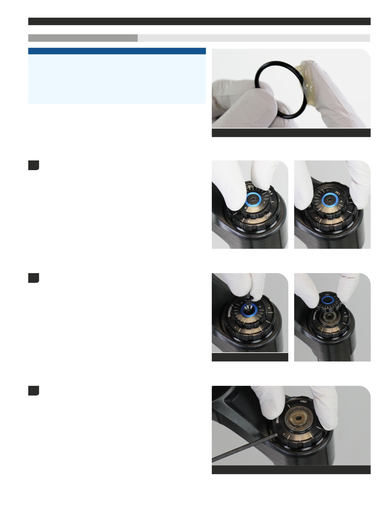
Damper Service
- Charger
3 RC2
200 Hour Service
Controls Removal
- Charger
3 RC2
NOTICE
Inspect each part for scratches. Do not scratch any sealing surfaces when
servicing your suspension. Scratches can cause leaks.
When replacing seals and o-rings, use your fingers or a pick to remove the
seal or o-ring. Spray RockShox Suspension Cleaner or isopropyl alcohol
onto each part and clean with a clean lint-free shop towel.
Apply SRAM Butter Grease to the new seals and o-rings.
SRAM Butter Grease
Rotate the compression adjuster knobs counterclockwise, to the full
1
open positions, until they stop.
Remove the (LSC) low speed compression knob retaining screw.
2
Remove the LSC adjuster knob.
2.5 mm
Loosen the (HSC) high speed compression knob set screw. Do not
3
remove the set screw.
2.5 mm
Damper Service - Charger 3 RC2
74
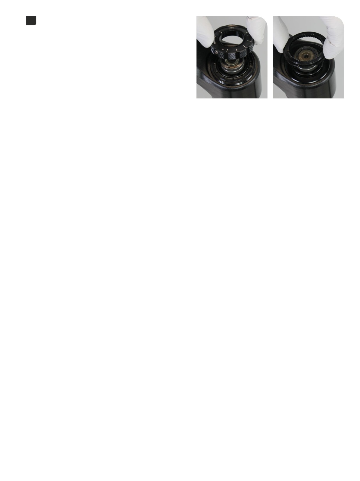
Remove the (HSC) high speed compression adjuster knob.
4
Remove the detent plate.
75
Controls Removal - Charger 3 RC2
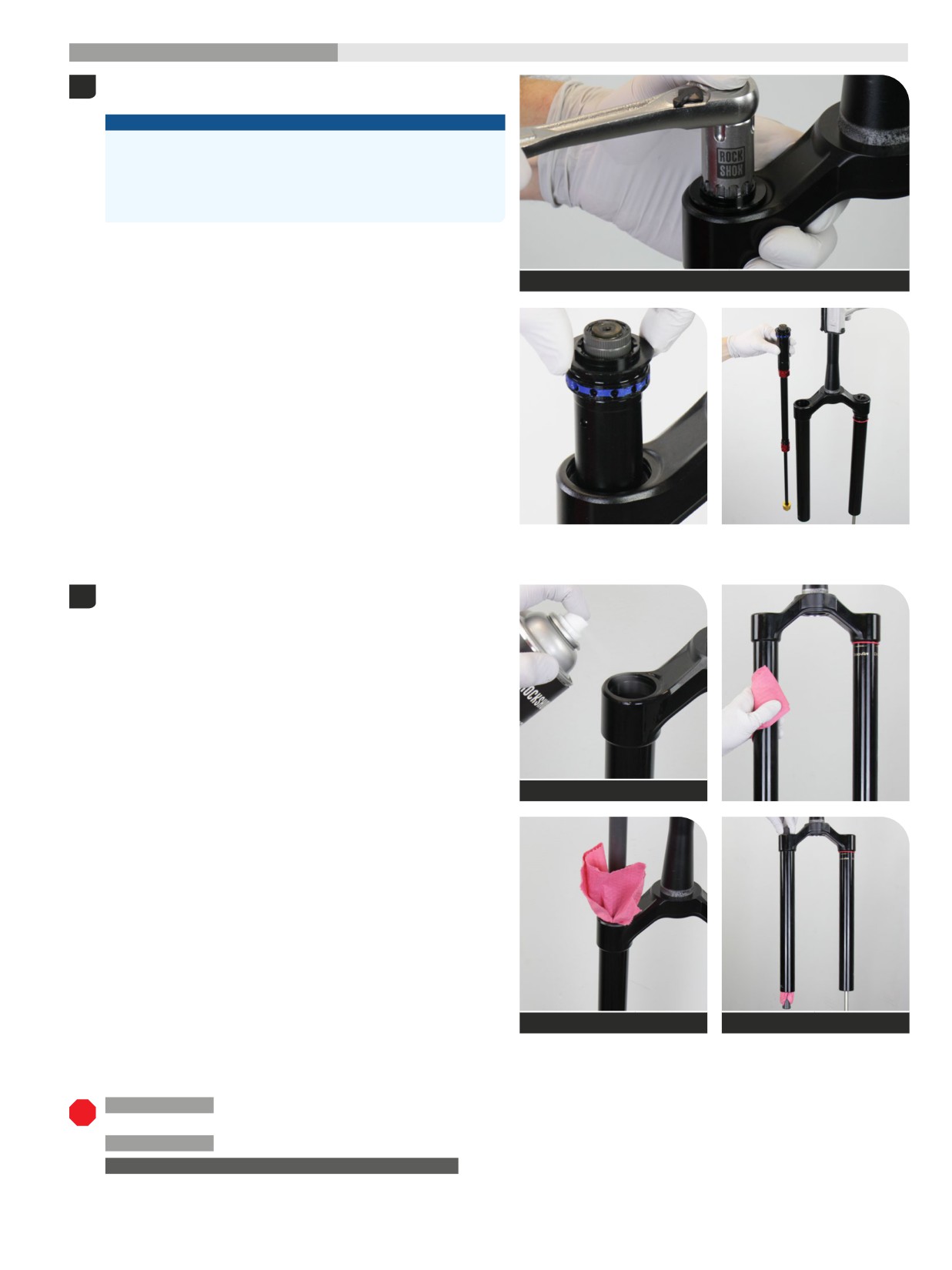
200 Hour Service
Damper Removal
- Charger
3 RC2
Unthread the damper top cap and remove the damper assembly. Press
1
down firmly when loosening the top cap.
NOTICE
The fork top caps are tightened to a high torque value. Ensure the
fork is held securely in the bicycle stand. To avoid damage to the
top cap, press the top cap / cassette tool squarely and firmly down
when loosening. Use a socket wrench with a long handle for extra
leverage.
Top cap / Cassette tool
Clean the inside and outside of the upper tube.
2
Clean the upper tube threads.
RockShox Suspension Cleaner
Dowel
Dowel
200 Hour Service Ultimate - Charger 3 RC Damper - Damper Service: Continue with ButterCups Removal - Damper Shaft - Charger 3 RC2 -
Ultimate.
200 Hour Service Select+ - Charger 3 RC Damper - Damper Service: Continue with Damper Service - Charger 3 RC2.
UPGRADE - CHARGER 3 RC2 DAMPER WITH BUTTERCUPS
Select+, Select, Base: To install a Charger 3 RC2 damper assembly with
pre-installed ButterCups, proceed to Damper Installation - Charger 3 RC2.
Damper Removal - Charger 3 RC2
76
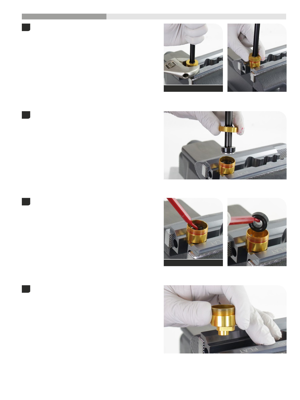
200 Hour Service
ButterCups Removal
- Charger
3 RC2
- Ultimate
Clamp the lower ButterCups housing into a vise with Reverb Vise
1
Blocks on the wrench flats, with the damper oriented upward.
Hold the damper shaft for support and unthread the upper ButterCups
housing (25 mm) from the lower housing.
Adjustable or 25 mm open end wrench
Remove the damper assembly from the lower cup and set it aside.
2
Remove the lower ButterCups bumper from the lower ButterCups
3
housing and discard it.
Do not remove the alignment bolt.
Pick (non-metallic)
Remove the lower ButterCups housing from the vise. Clean the lower
4
ButterCups housing.
77
ButterCups Removal - Charger 3 RC2 - Ultimate
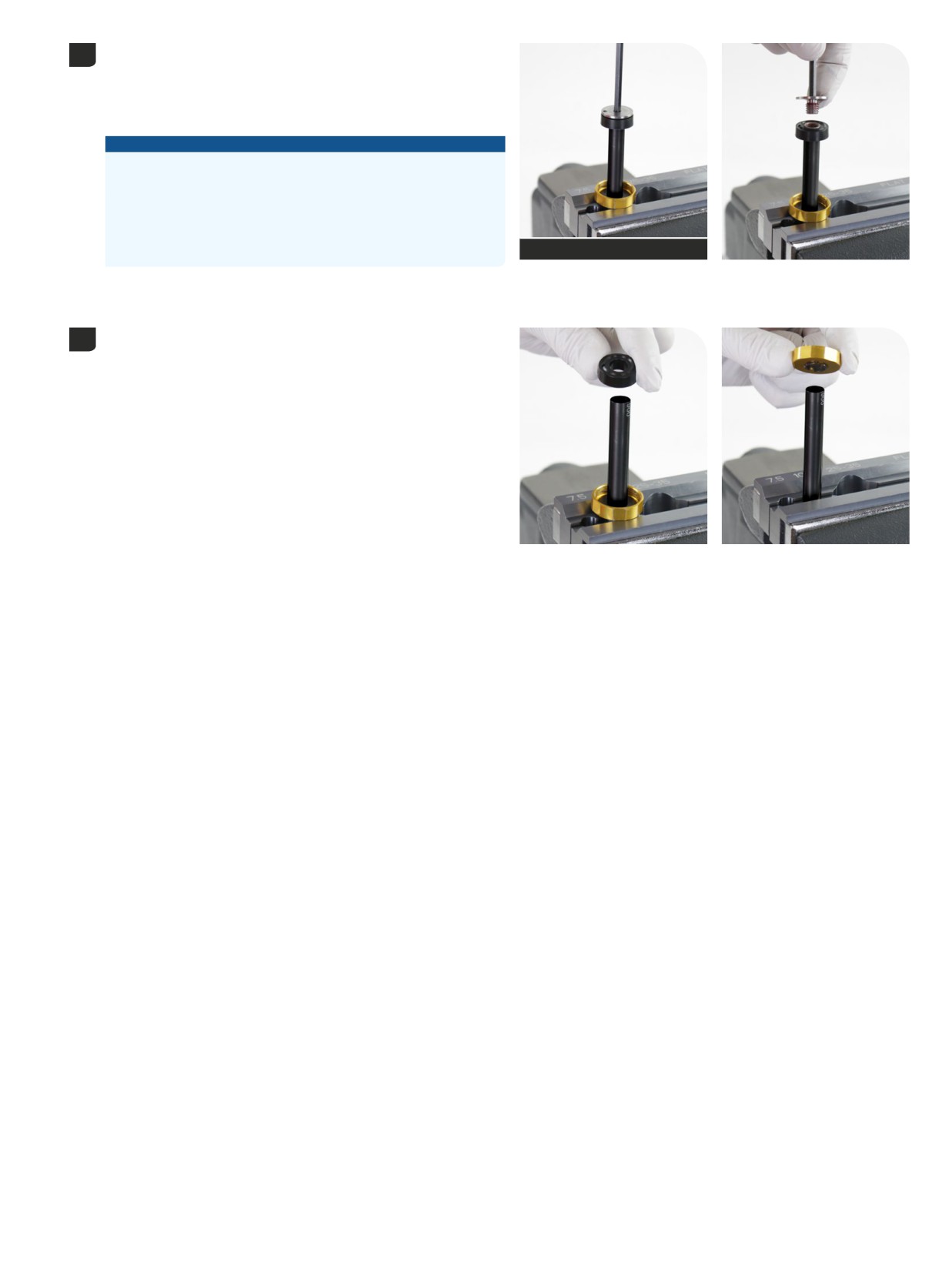
Clamp the damper shaft into the 10 mm slot of the Reverb Vise Blocks
5
or RockShox Rear Shock Vise Blocks with the damper oriented
downward.
Clamp the damper shaft only tight enough so it does not spin when the
ButterCups shaft end plate is removed.
NOTICE
Scratches can cause oil to leak. Replace the rebound damper
assembly if a scratch is visible.
Do not clamp the rebound damper shaft in the middle of the shaft.
Clamping force will damage the rebound damper shaft. If the
rebound damper shaft is damaged, the rebound damper assembly
must be replaced.
T25
Reverb Vise Blocks (10 mm)
Unthread and remove the ButterCups shaft end plate from the damper
shaft.
Remove the upper ButterCups bumper and discard it.
6
Remove the upper ButterCups housing and bushing assembly from the
damper shaft.
78
ButterCups Removal - Charger 3 RC2 - Ultimate
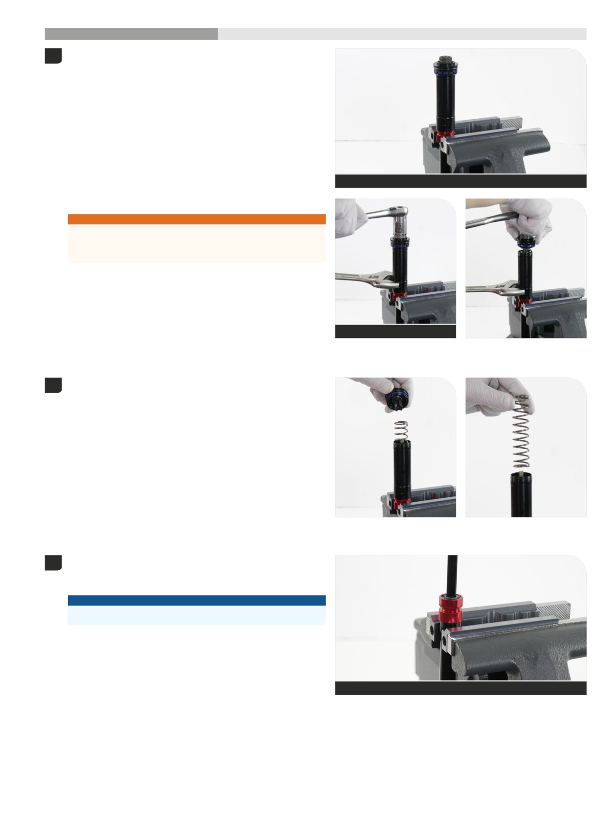
200 Hour Service
Damper Service
- Charger
3 RC2
Clamp the damper IFP tube coupler (red) in a vise with Reverb Vise
1
Blocks, top cap oriented upward.
Reverb Vise Blocks - flat
Hold and secure the IFP tube with an open end wrench (28mm).
⚠WARNING
The top cap is spring loaded by the IFP spring. To prevent the spring
and top cap from ejecting outward when it is unthreaded, press down
on the socket wrench and top cap while unthreading the top cap.
Unthread the top cap from the IFP tube. Press down on the socket
wrench and top cap until the top cap is completely unthreaded.
Top cap / Cassette tool
28 mm
Remove the top cap and IFP spring from the IFP tube.
2
Remove the damper assembly from the vise.
3
Clamp the cartridge tube, on the wrench flats, into the vise with the
rebound damper oriented upward.
NOTICE
Place an oil pan below the vise to collect oil that drips.
Reverb Vise Blocks - flat
Damper Service - Charger 3 RC2
79
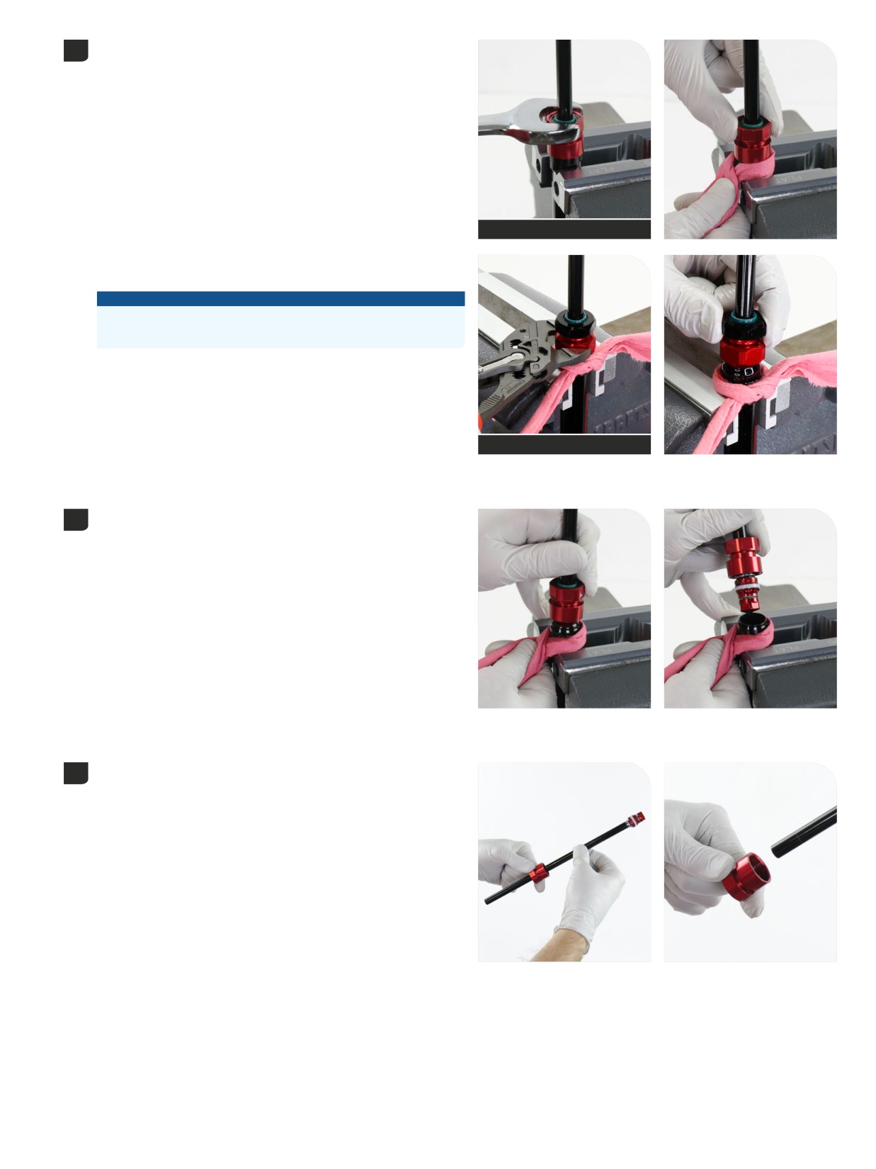
Secure a shop towel around the cartridge tube under the sealhead to
4
absorb oil.
Unthread the sealhead from the cartridge tube.
Adjustable or 23 mm open end wrench
Two-Piece Rebound Sealhead: Unthread the red section of the
sealhead from the cartridge tube.
NOTICE
To avoid separation of the two seahead sections, only unthread the
sealhead from the cartridge tube at the red section.
Adjustable or 23 mm open end wrench
Remove the sealhead and rebound damper from the cartridge tube.
5
Remove the sealhead assembly from the rebound damper.
6
Discard the sealhead assembly.
Damper Service - Charger 3 RC2
80
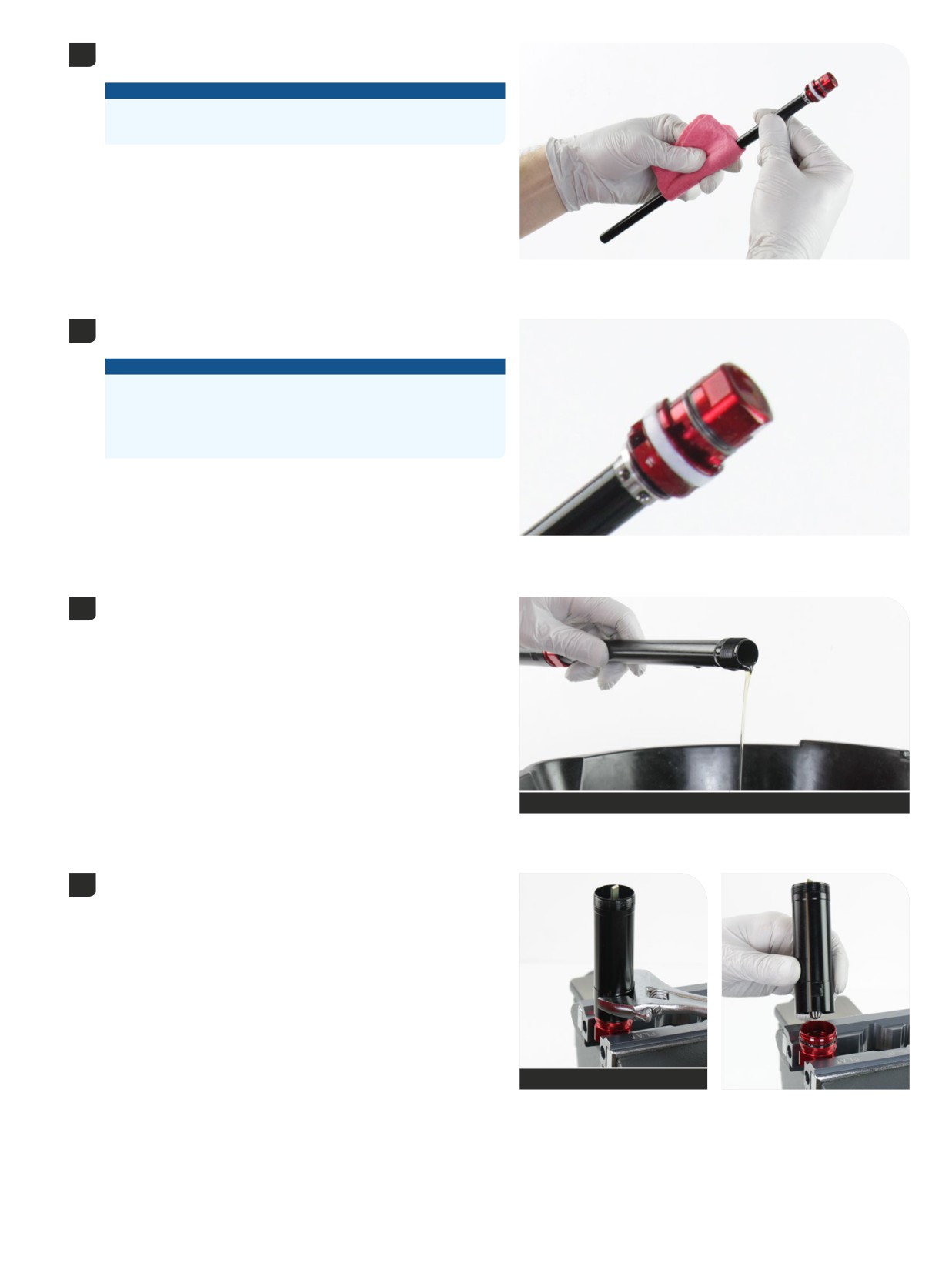
Clean the rebound damper assembly, check for scratches on the shaft,
7
and set it aside.
NOTICE
Scratches can cause oil to leak. Replace the rebound damper
assembly if a scratch is visible.
The solid band glide ring is not removable and only requires cleaning.
8
Do not remove.
NOTICE
Do not remove the solid band glide ring. The solid band glide ring is
not serviceable. Removal of the solid band glide ring will require a
new damper assembly.
The color of the solid band glide ring may vary.
Remove the cartridge tube from the vise and pour the damper oil into
9
an oil pan.
Oil pan
Clamp the damper tube assembly back into the vise on the IFP tube
10
coupler (red) hex wrench flats, with the IFP tube oriented upward.
Unthread and remove the IFP tube assembly from the IFP coupler (red).
Remove the cartridge tube from the vise and set it aside.
28 mm or adjustable open end wrench
Damper Service - Charger 3 RC2
81
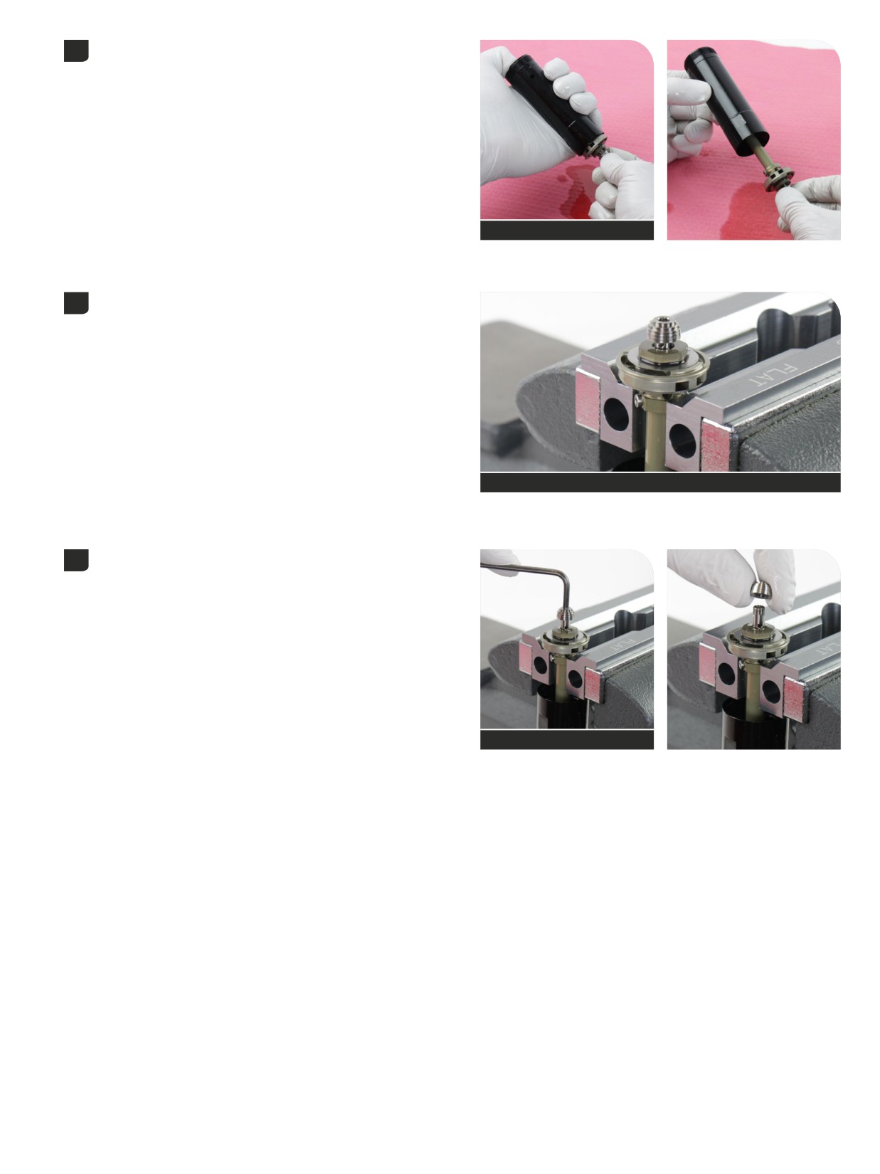
The IFP tube assembly may contain damping oil. Hold the IFP tube
11
assembly, with the exterior hex end downward, over shop towel.
From the exterior threaded end of the IFP tube, press the adjuster tab
and push the compression damper assembly out of the IFP tube until
the piston assembly exits the IFP tube. Oil will drain onto the shop
towel.
Shop towel
With the piston above the Reverb Vise Blocks, lightly clamp the
12
compression damper hex cam into the vise. Do not clamp on the set
screws.
The IFP tube should be below the vise blocks.
Reverb Vise Blocks - flat
Unthread and remove the (HSC) high speed compression nut from the
13
compression damper assembly.
Set the nut aside.
3 mm hex
Damper Service - Charger 3 RC2
82
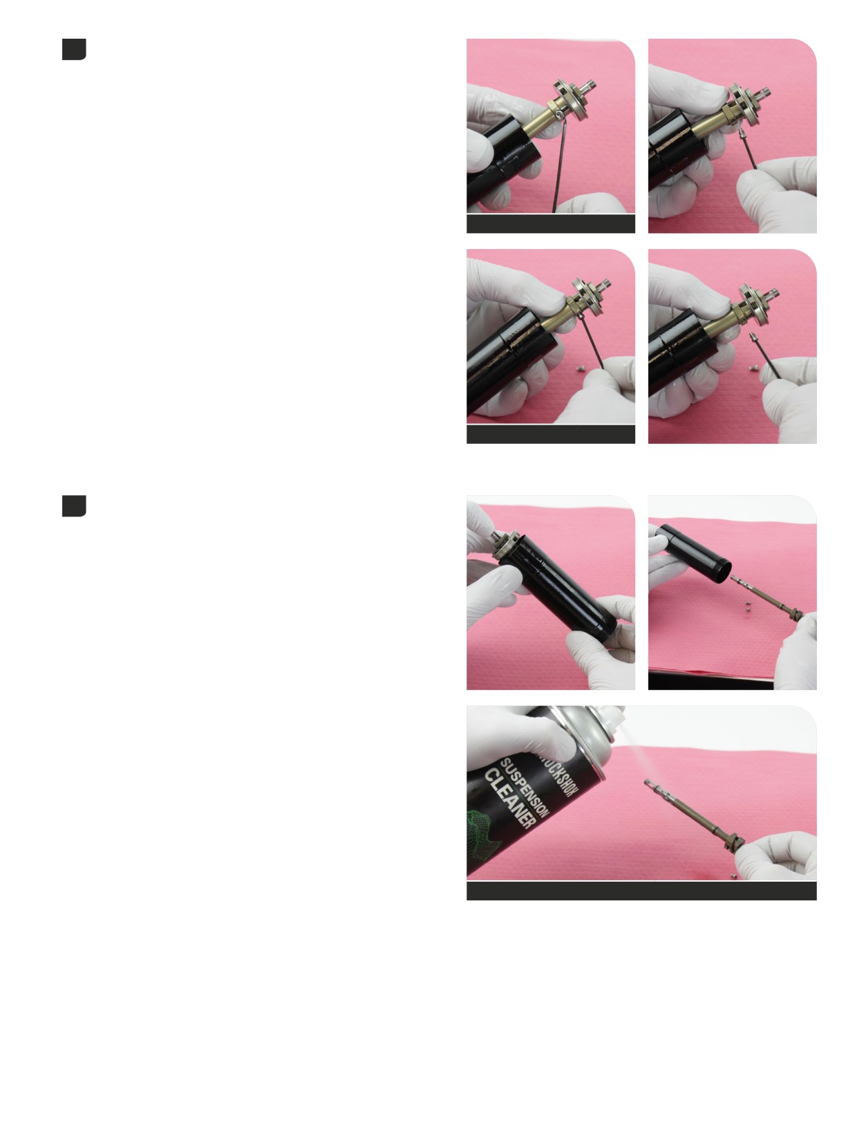
Remove the compression damper assembly and IFP tube from the vise.
14
Unthread and remove each cam set screw (x2).
Set the set screws aside.
1.5 mm hex
1.5 mm hex
Remove the (LSC) low speed compression assembly from the (HSC)
15
high speed compression/piston assembly.
Spray the assembly with RockShox Suspension Cleaner or isopropyl
alcohol and set it aside.
RockShox Suspension Cleaner
Damper Service - Charger 3 RC2
83
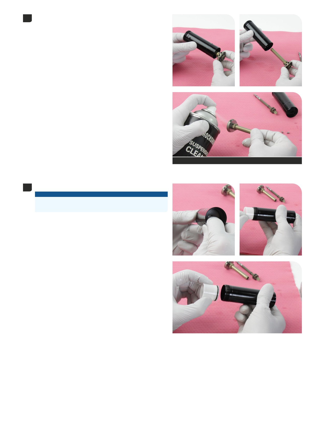
Remove the (HSC) high speed compression/piston assembly from the
16
IFP tube.
Spray the assembly with RockShox Suspension Cleaner or isopropyl
alcohol and set it aside.
RockShox Suspension Cleaner
Push the IFP out of the IFP tube and remove it.
17
NOTICE
Do not srcatch the inside surface of the IFP tube. Scratches can
cause oil to leak. Replace the IFP tube if a scratch is visible.
Damper Service - Charger 3 RC2
84
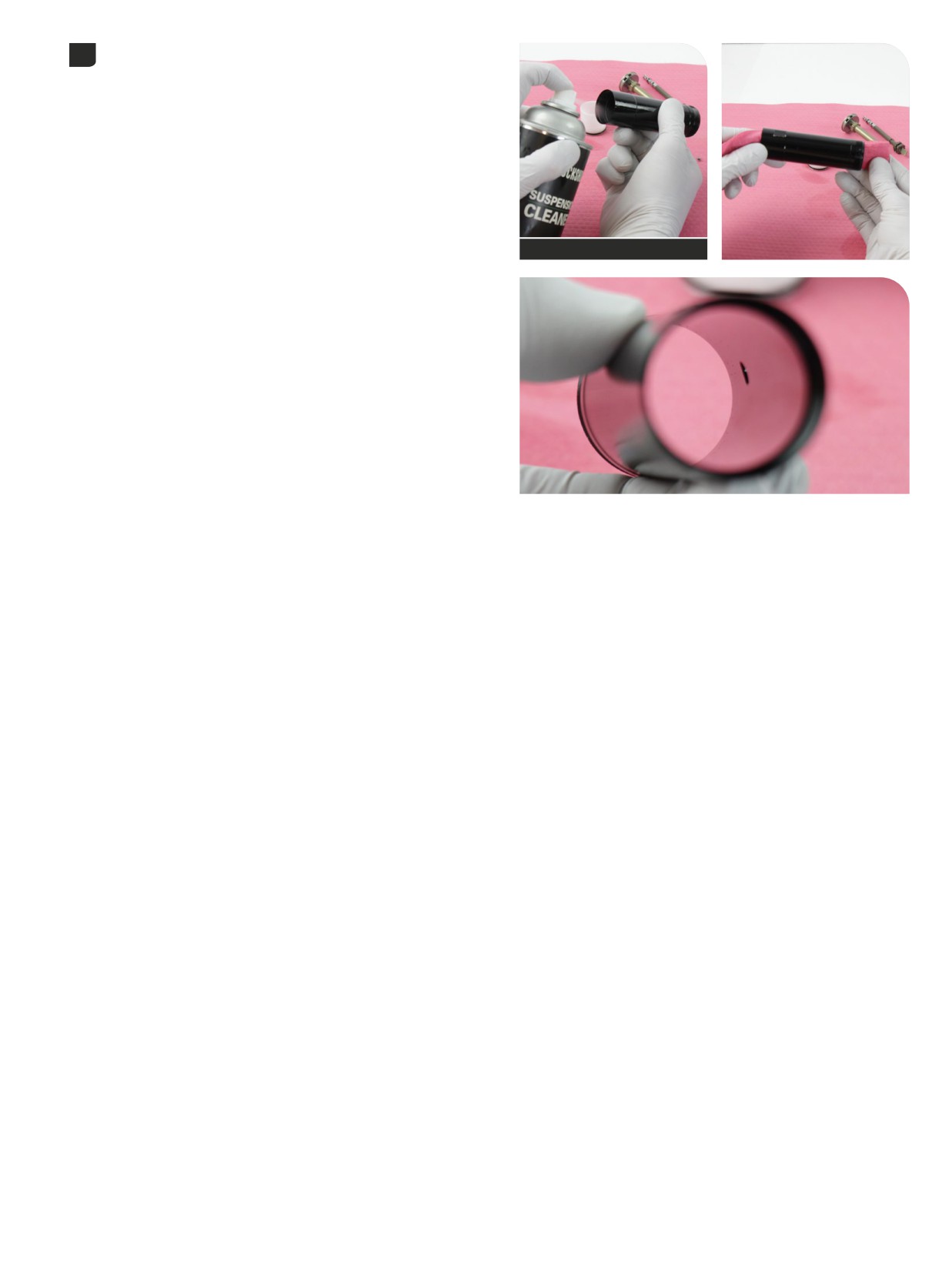
Clean the IFP tube and inspect it for scratches. Set the IFP tube aside.
18
RockShox Suspension Cleaner
Damper Service - Charger 3 RC2
85
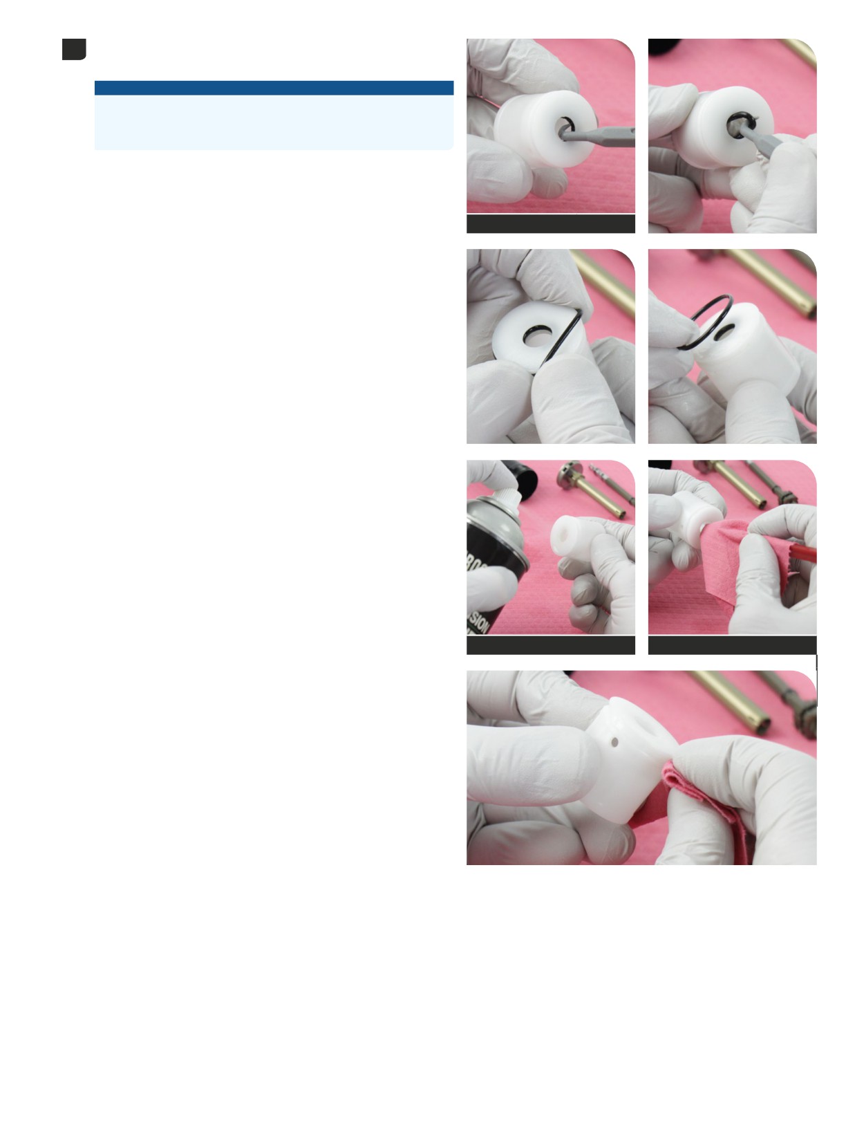
Remove the inner and outer IFP o-rings and discard them.
19
Clean the IFP and inspect it for scratches.
NOTICE
DO NOT SCRATCH the o-ring grooves in the IFP. Scratches will
cause oil to leak. The IFP MUST be replaced if a scratch is visible in
the o-ring grooves.
Pick (non-metallic)
RockShox Suspension Cleaner
Pick (non-metallic)
Damper Service - Charger 3 RC2
86
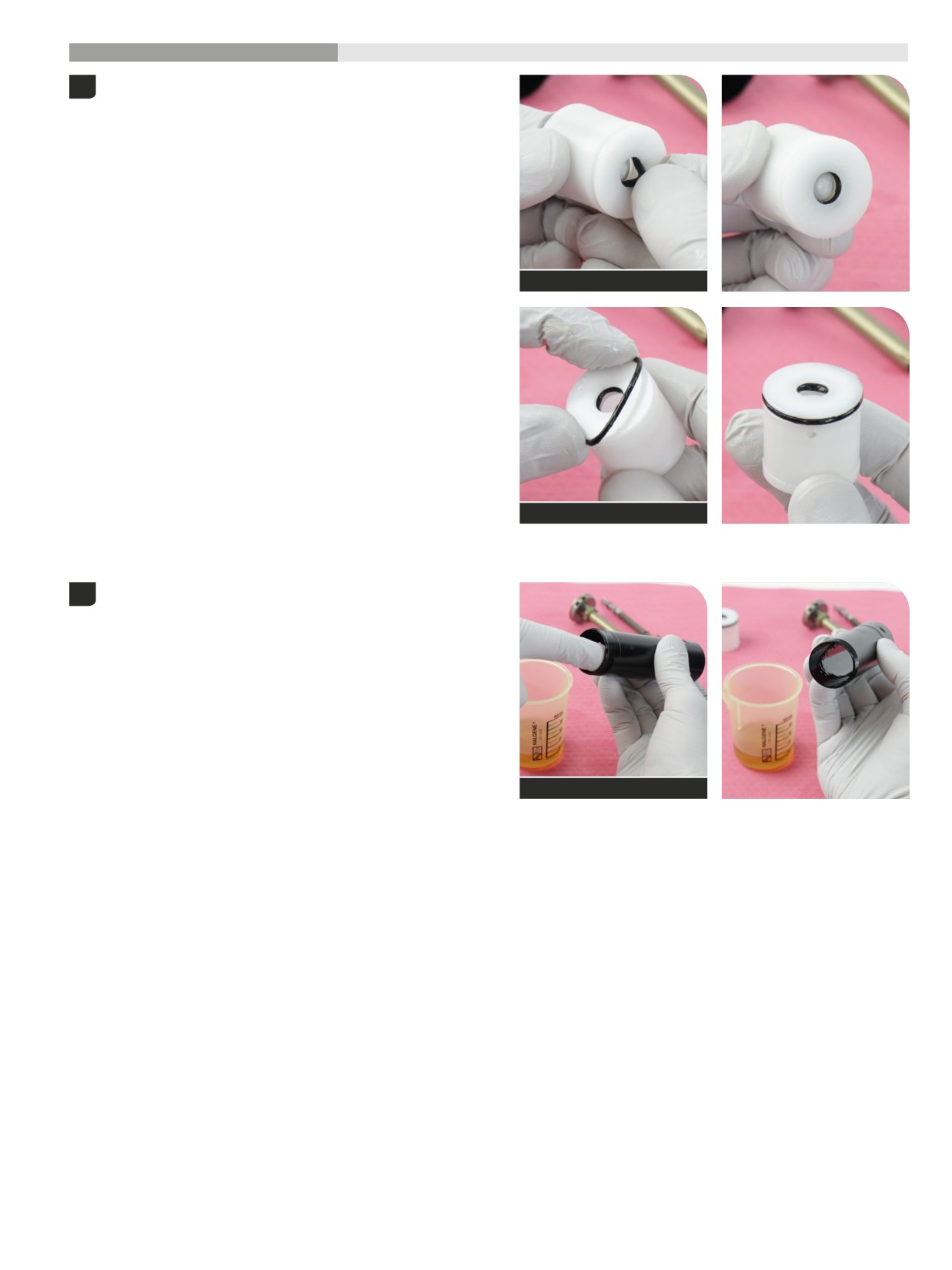
200 Hour Service
Damper Assembly
- Charger
3 RC2
Apply grease to the new inner and outer IFP o-rings and install them
1
onto the IFP.
SRAM Butter Grease
SRAM Butter Grease
Apply a thin coat of suspension oil to the inner surface of the IFP tube.
2
Maxima PLUSH 7wt suspension oil
Damper Assembly - Charger 3 RC2
87
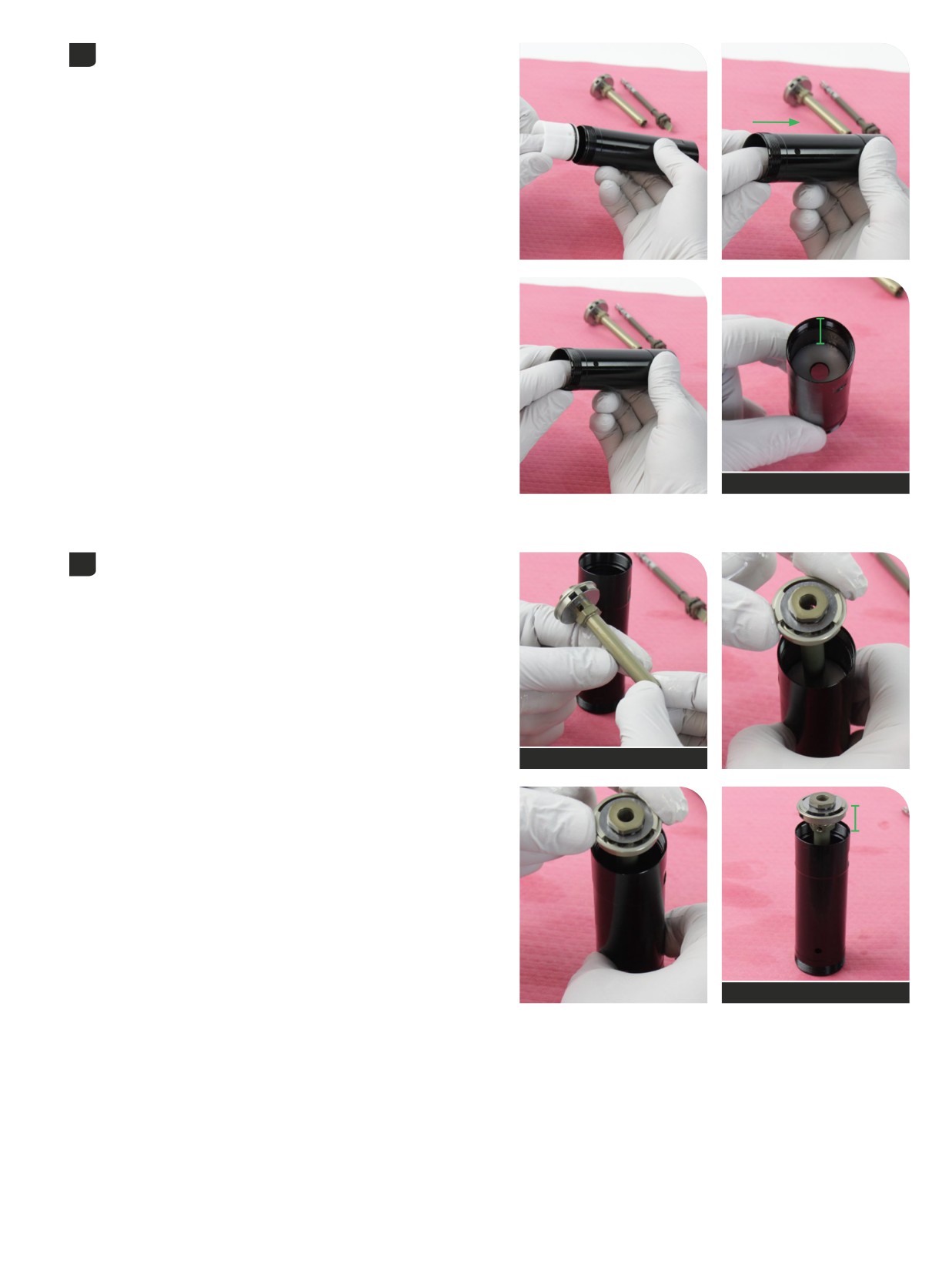
Insert and install the IFP into the IFP tube, flat end/outer o-ring first, into
3
the outer threaded end of the IFP tube.
Press the IFP into the IFP tube until it is approximately 30 mm from the
end of the opposite (internal threads) end of the tube.
30 mm
Apply a light coat of suspension oil to the (HSC) high speed
4
compression/piston assembly shaft (outer/wider shaft).
From the hex end of the IFP tube, insert the (HSC) high speed
compression/piston assembly into and through the center of the IFP.
Press it into the IFP until the piston assembly is approximately 20 mm
above the internal thread end of the IFP tube.
Maxima PLUSH 7wt suspension oil
20 mm
Damper Assembly - Charger 3 RC2
88
Apply suspension oil to the (LSC) low speed compression/piston
5
assembly shaft and o-rings (inner/narrow shaft).
Maxima PLUSH 7wt suspension oil
Hold the piston to keep it from moving.
6
From the external threaded end of the IFP tube, insert the (LSC) low
speed compression shaft assembly, silver narrow end first, into the
(HSC) high speed compression/piston assembly shaft.
Push the (LSC) low speed compression/piston assembly until the
narrow silver shaft end protrudes through the piston bolt, until it stops,
snaps into place, and is completely seated. The narrow end of the LSC
shaft should protrude through the piston bolt.
Damper Assembly - Charger 3 RC2
89
Install each cam set screw (2 total) evenly finger tight. Tighten each to
7
the specified torque.
The set screws secure the (LSC) low speed compression shaft in the
(HSC) high speed compression shaft.
1.5 mm
1.5 mm
0.56 N∙m (5 in-lb)
1.5 mm
1.5 mm
0.56 N·m (5 in-lb)
Pull the piston up until it is above the end of the IFP tube.
8
Clamp the (HSC) high speed compression assembly into the vise at the
cam hex wrench flats. The piston should be above the vise blocks and
the IFP tube should be below the vise blocks.
Do not clamp on the set screws.
Reverb Vise Blocks
90
Damper Assembly - Charger 3 RC2
Install the compression nut onto the inner (LSC) low speed
9
compression rod end and tighten it.
The LSC adjuster will rotate when the nut is tightened. Rotate it
counterclockwise back to full extension after the nut is tightened.
Remove the assembly from the vise.
3 mm
3 mm
1.13 N∙m (10 in-lb)
3 mm
Set the IFP: Using a non-metallic pick, push the IFP evenly into the
10
IFP tube until the hollow end (opposite side) is just below the IFP tube
bleed port hole (A). The IFP should not cover the bleed port hole.
Pick (non-metallic)
A
Damper Assembly - Charger 3 RC2
91
Push the piston down until it is approximately 10 mm above the end of
11
the IFP tube.
Inject suspension oil into the IFP tube until it is full. Oil will fill the IFP
tube above the IFP and below the piston.
10 mm
Maxima PLUSH 7wt suspension oil
Hold a shop towel around the IFP tube.
12
Push the piston down and into the IFP tube until it stops.
Remove the o-ring from the red cartridge tube coupler and discard it.
13
Clean the o-ring groove.
Damper Assembly - Charger 3 RC2
92
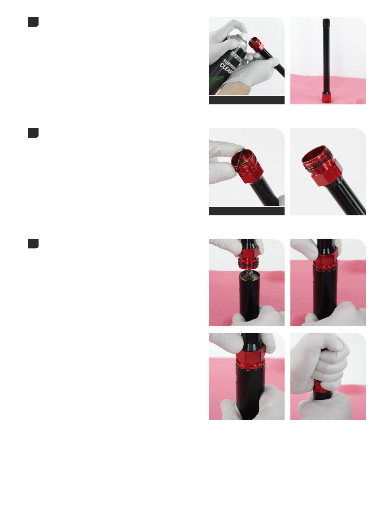
Spray RockShox Suspension Cleaner into the cartridge tube and set
14
upright on a shop towel to drain.
RockShox Suspension Cleaner
Apply grease to a new o-ring and install it onto the red coupler.
15
SRAM Butter Grease
Hold the IFP secure so it does not move.
16
Thread the IFP tube coupler onto the IFP tube and tighten it hand tight.
Damper Assembly - Charger 3 RC2
93
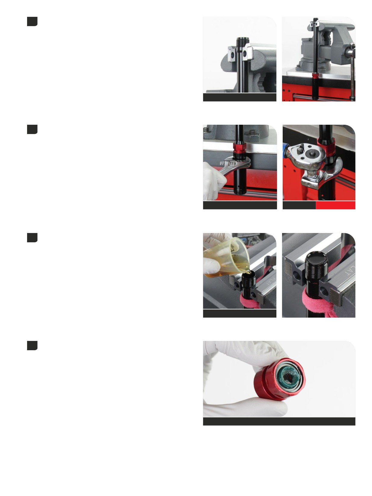
Clamp the cartridge tube assembly into the vise at the wrench flats with
17
the IFP tube/assembly oriented downward.
Reverb Vise Blocks - Flat
Tighten the IFP tube and IFP coupler onto the cartridge tube. When
18
tightened, the IFP tube, IFP coupler, and cartridge tube will all be
tightened to the same torque.
28 mm or adjustable wrench
28 mm
14 N·m (125 in-lb)
Secure a shop towel around the cartridge tube.
19
Pour suspension oil into the cartridge tube unti it is full.
Maxima PLUSH 7wt suspension oil
Apply grease to the wiper seal on the new rebound damper sealhead
20
assembly.
SRAM Butter Grease
Damper Assembly - Charger 3 RC2
94
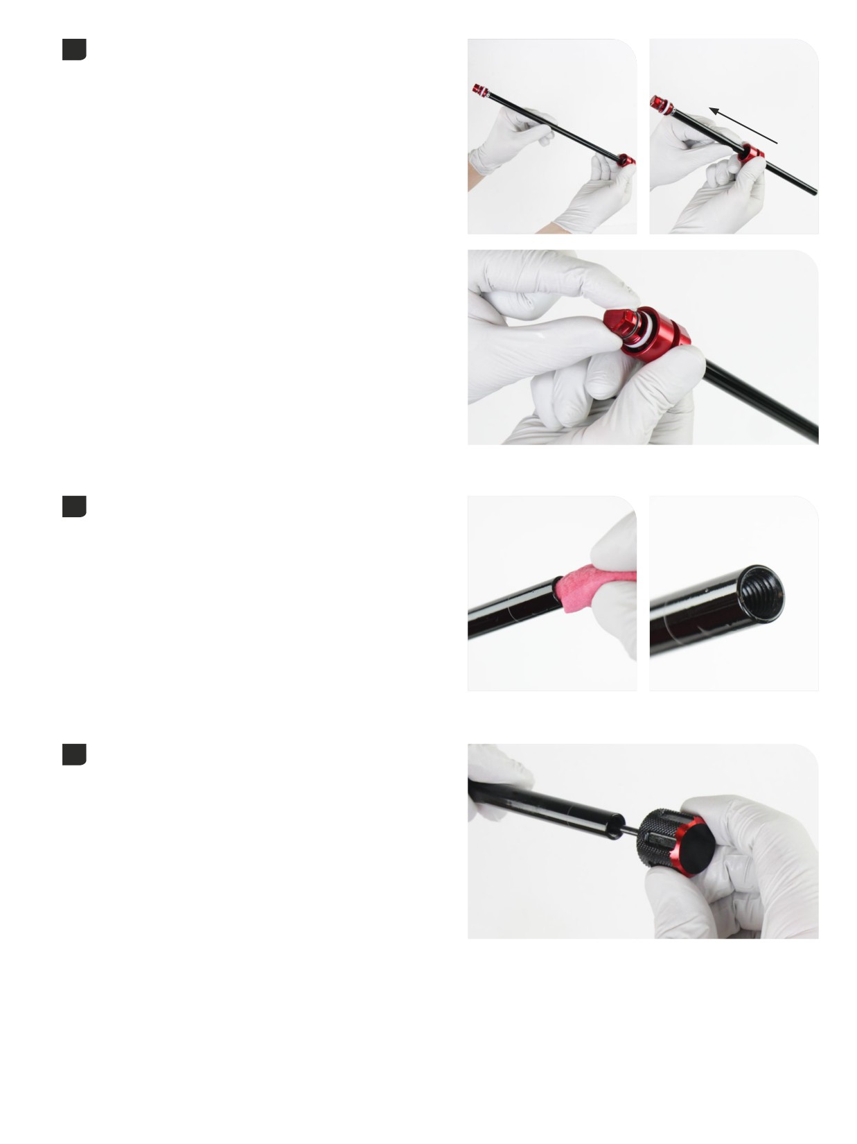
Install the sealhead assembly onto the rebound damper shaft and slide
21
it to the rebound piston until it stops.
Clean the grease from the shaft threads.
22
Insert the rebound adjuster knob in the rebound shaft and rotate
23
counterclockwise until it stops. This is the full open rebound setting.
Damper Assembly - Charger 3 RC2
95
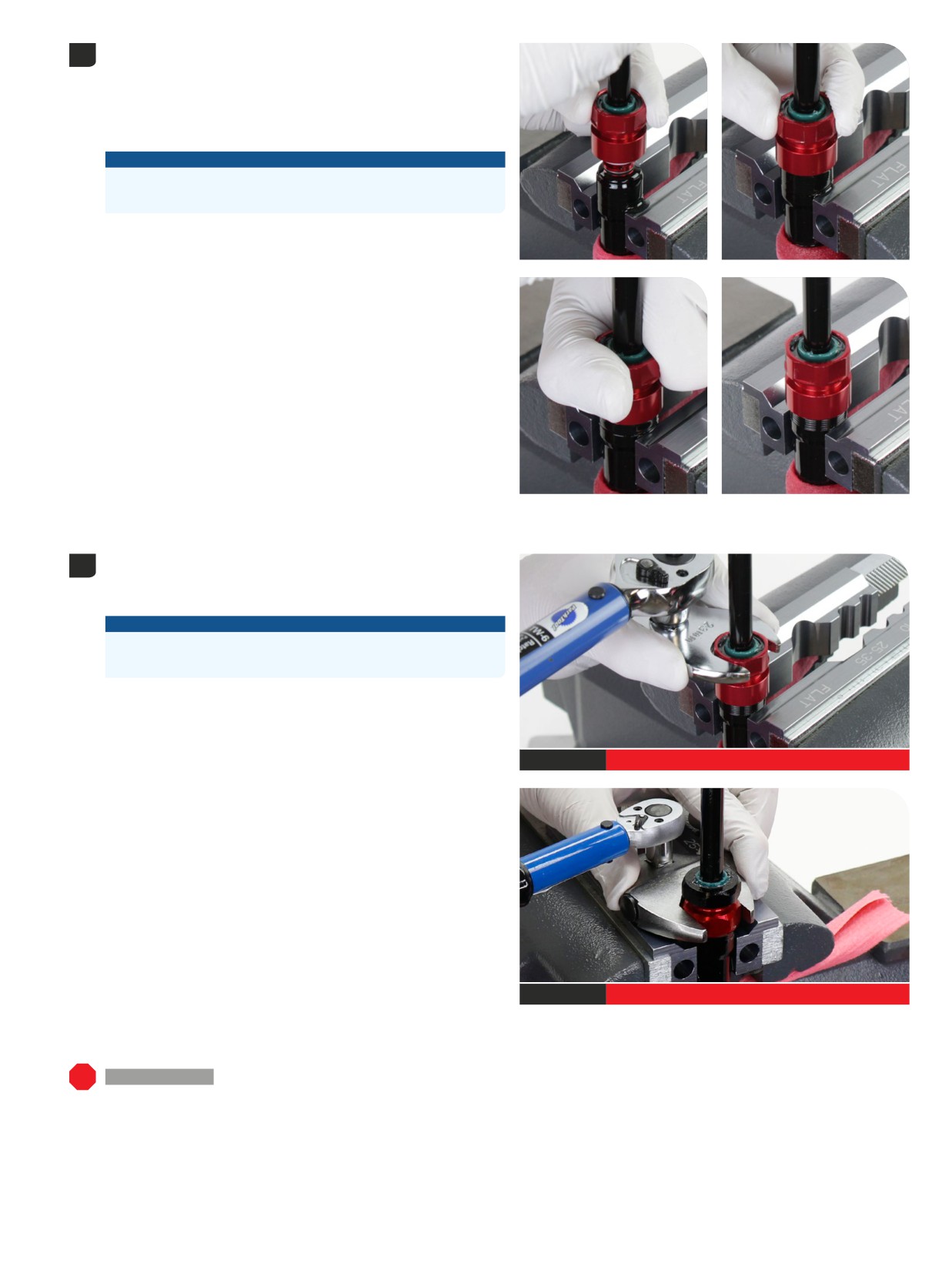
Secure a shop towel around the damper tube to absorb displaced oil.
24
While pulling up on the rebound damper to maintain contact with the
sealhead, insert the rebound damper piston into the cartridge tube.
Continue to apply opposing pressure to the sealhead with the rebound
damper and thread the sealhead onto the end of the cartridge tube
until it is hand tight.
NOTICE
Do not push the rebound damper into the cartridge tube while
threading the sealhead onto the cartridge tube.
Tighten the sealhead to the specified torque.
25
Two-Piece Rebound Sealhead: Tighten the red section of the sealhead
to the cartridge tube.
NOTICE
Scratches can cause oil to leak. Replace the rebound damper
assembly if a scratch is visible.
Remove the damper from the vise.
Clean damper assembly.
23 mm
14 N·m (125 in-lb)
23 mm
14 N·m (125 in-lb)
200 Hour Service Select+: Charger 3 RC2 Damper - Damper Service: Continue with Damper Bleed - Charger 3 RC2.
Damper Assembly - Charger 3 RC2
96
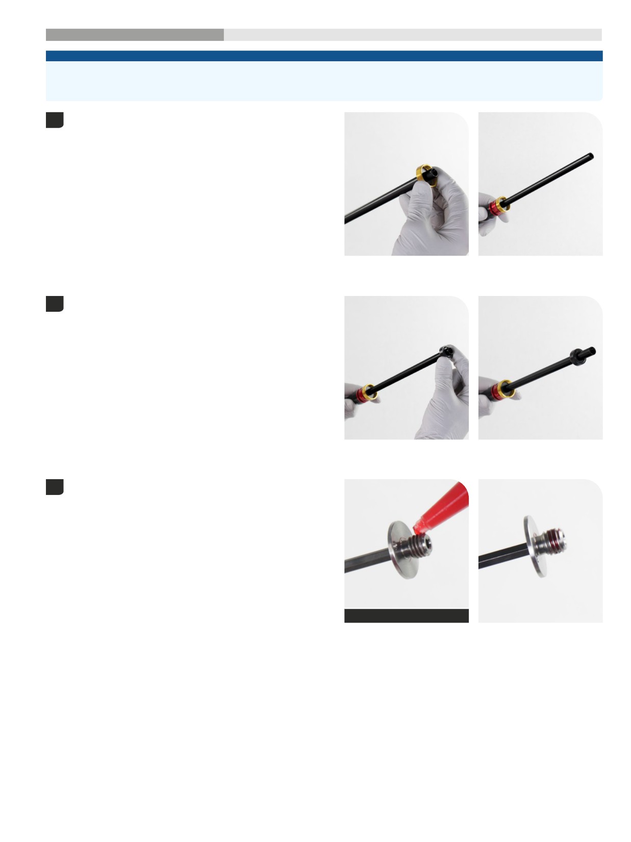
200 Hour Service
ButterCups Installation
- Charger
3 RC2
- Ultimate
NOTICE
The Ultimate Charger 3 RC2 damper shaft ButterCups assembly is NOT compatible with Select+ Charger 3 RC2, Select Charger RC, and
Base Rush RC rebound damper shafts. Do NOT install a damper shaft ButterCups assembly onto a Select+ Charger 3 RC2, Select Charger RC, or
Base Rush RC damper shaft.
Install the upper ButterCups housing and bushing assembly onto the
1
damper shaft. Slide the assembly toward the rebound sealhead until it
stops.
Install a new upper ButterCups bumper, wide end first, onto the
2
damper shaft.
Apply Threadlocker Loctite 2760 (red), or equivalent, to the first three
3
full threads on the end of the end plate.
Threadlocker Loctite 2760 - Red
97
ButterCups Installation - Charger 3 RC2 - Ultimate
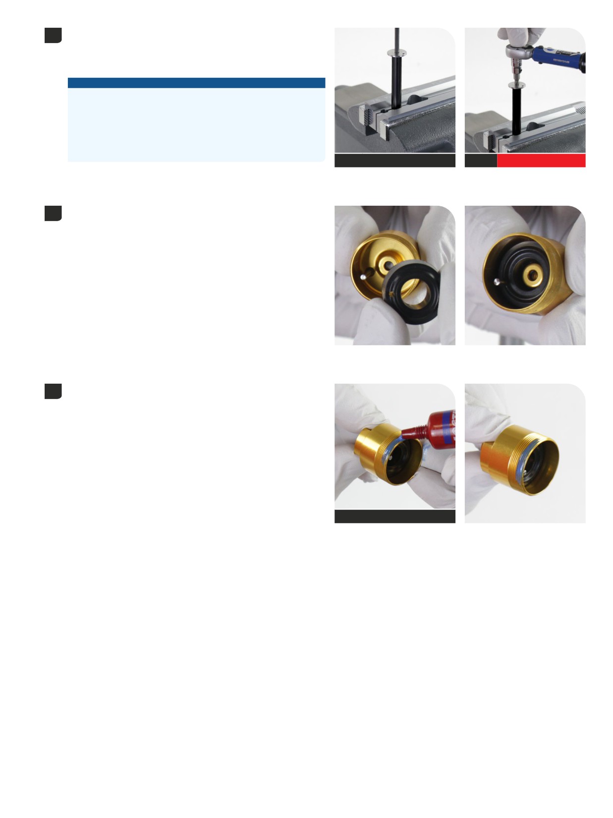
Clamp the damper shaft into the 10 mm slot of the Reverb Vise Blocks
4
or RockShox Rear Shock Vise Blocks.
Clamp the damper shaft only tight enough so it does not spin when the
ButterCups shaft end plate is tightened.
NOTICE
Scratches can cause oil to leak. Replace the rebound damper
assembly if a scratch is visible.
Do not clamp the rebound damper shaft in the middle of the shaft.
Clamping force will damage the rebound damper shaft. If the
rebound damper shaft is damaged, the rebound damper assembly
must be replaced.
T25
Reverb Vise Blocks (10 mm)
T25
5 N∙m (45 in-lb)
Thread the ButterCups shaft end plate into the damper shaft and
tighten it.
Install the lower ButterCups housing bumper into the lower ButterCups
5
housing, wide side down, in alignment with the bolt.
Apply Threadlocker Loctite 242 (blue), or equivalent, to three full outer
6
threads on the lower ButterCups housing.
Theadlocker Loctite 242 - Blue
98
ButterCups Installation - Charger 3 RC2 - Ultimate
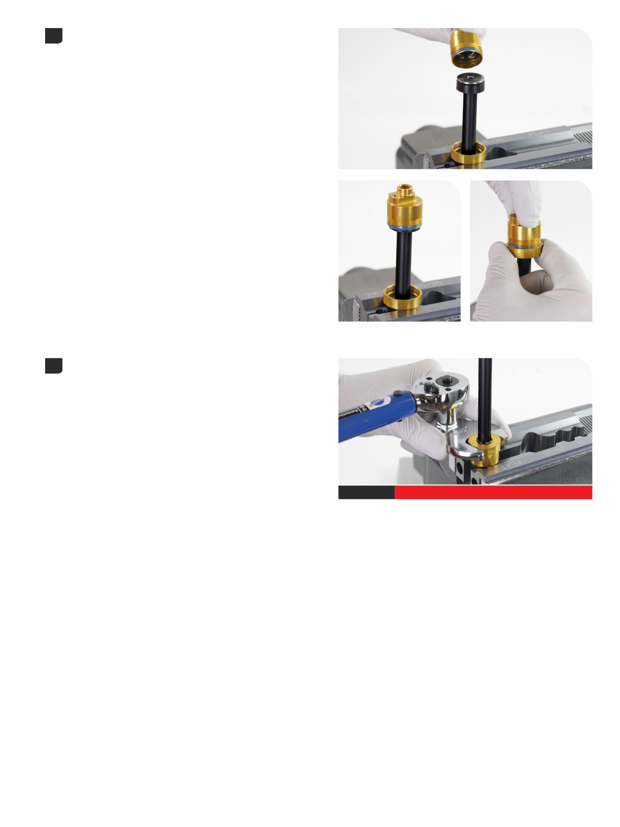
Position the upper ButterCups housing and bumper above the vise
7
blocks.
Install the lower ButterCups housing/bumper assembly onto the
ButterCups shaft end plate; insert the bolt through the end plate bolt
hole.
Slide lower cup to the upper bumper end plate, and position the
alignment bolt through the hole on the end plate.
Thread the upper ButterCups housing onto the lower ButterCups
housing finger tight.
Remove the damper shaft from the vise and vise blocks.
8
Clamp the lower ButterCups housing into a vise with RockShox Vise
Blocks on the wrench flats, damper oriented upward.
Tighten the upper ButterCups housing onto the lower housing.
25 mm
14 N∙m (125 in-lb)
99
ButterCups Installation - Charger 3 RC2 - Ultimate
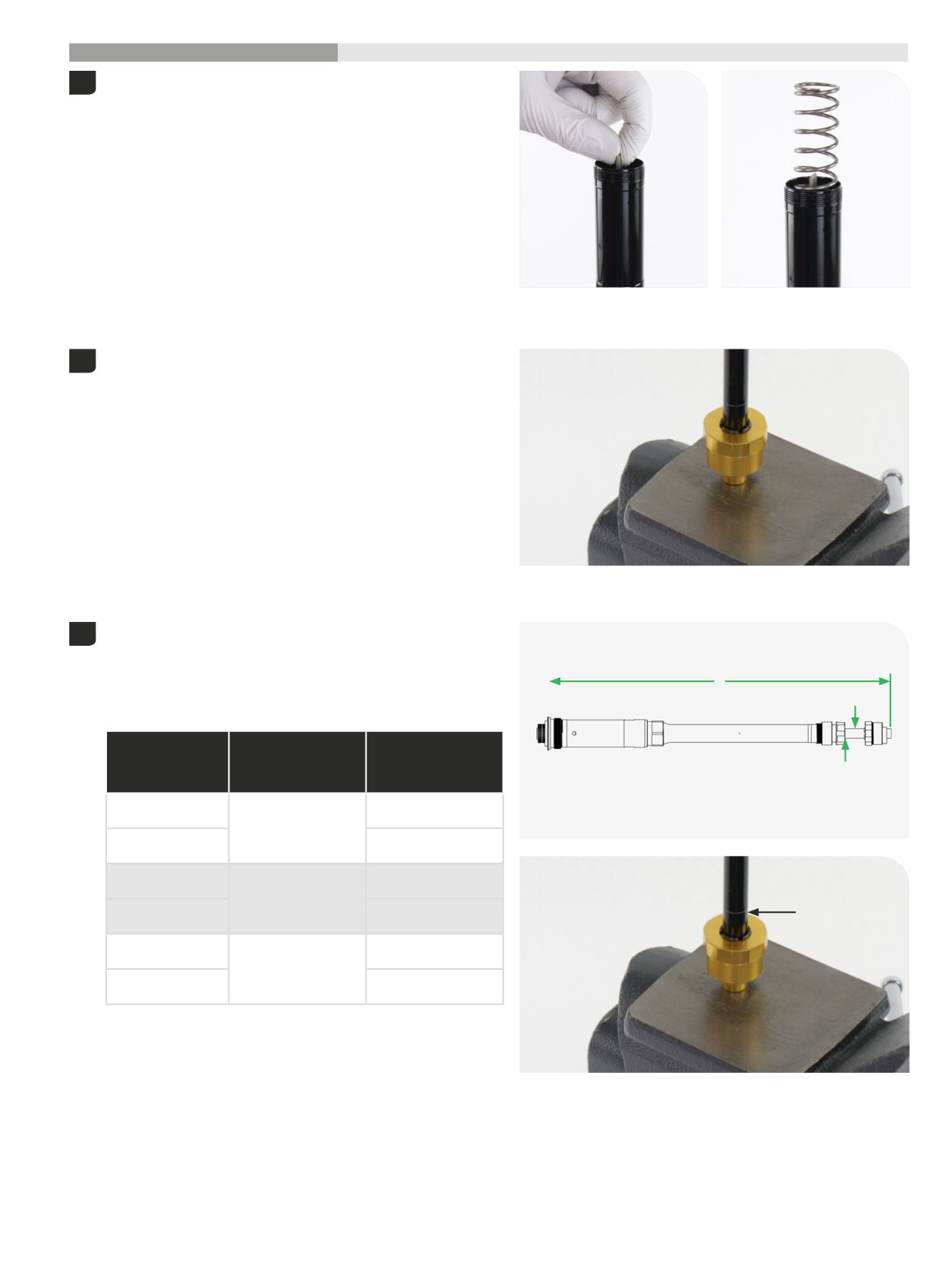
200 Hour Service
Damper Bleed
- Charger
3 RC2
Rotate the adjuster tab counterclockwise until it stops. This is the full
1
open position.
Insert the IFP coil spring into the IFP damper tube. The spring will rest
on top of the IFP.
Position the ButterCups (Ultimate), or rebound damper shaft (Select+),
2
end on a flat surface.
Ultimate with ButterCups is pictured. The procedure is the same for
Select+ without ButterCups.
Optional: Clamp the ButterCups or rebound damper shaft end in the
vise with Reverb Vise Blocks for added stability if needed.
To purge oil from above the IFP, the IFP must be manually compressed
3
into the IFP tube with the IFP spring, while the rebound damper is
compressed and cycled into the cartridge damper tube.
Locate the bleed line (C) on the rebound damper shaft. During the
A
bleed process, the damper should be compressed to the bleed line (C),
B
or to the total length (A) listed in the table below.
B - Rebound Shaft /
A - Total Damper
Fork Model Reference
Fork
Length (mm) when
Number (printed on
C
Compressed
rebound damper shaft)
Pike Ultimate with
100
ButterCups
360
Pike Select+ with no
150
ButterCups
Lyrik Ultimate with
200
ButterCups
377
Lyrik Select+ with no
C
250
ButterCups
ZEB Ultimate with
300
ButterCups
401
ZEB Select+ with no
350
ButterCups
1
Damper Bleed - Charger 3 RC2
00
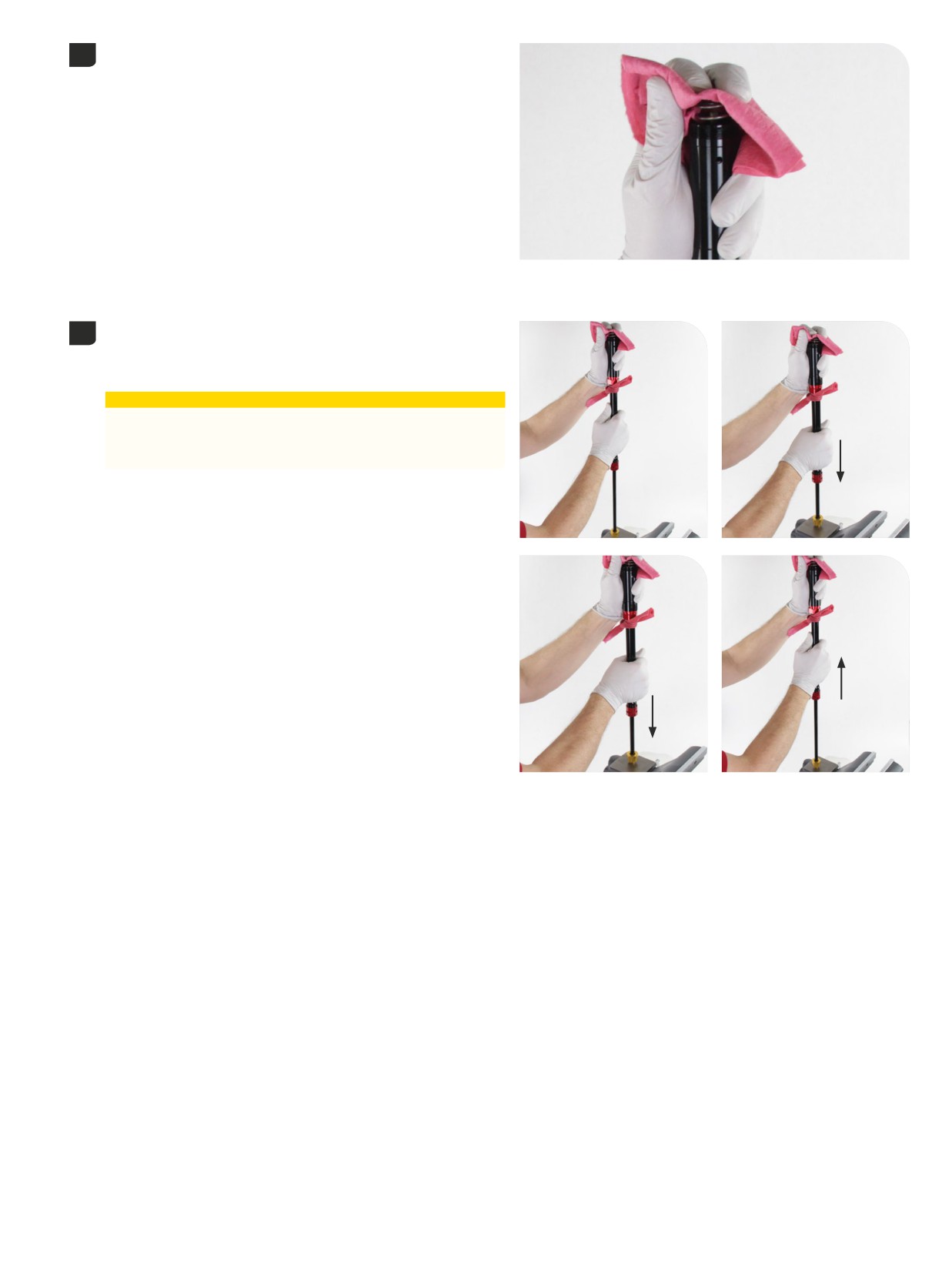
Place a shop towel over the IFP spring.
4
Press the IFP coil spring down and into the IFP tube about half way,
and hold it steady. This pushes the IFP into the IFP tube and applies
opposing force, creating pressure within the cartridge tube.
While holding the IFP spring compressed, slowly push the damper
5
down about half way to the bleed line, then allow the damper to fully
extend. Repeat this 2 more times, or until air cannot be heard moving
through the damper.
⚠CAUTION
Oil may exit the cartridge tube bleed hole. Wear safety glasses
and keep your eyes and face away from the bleed hole when
compressing the rebound damper.
1
Damper Bleed - Charger 3 RC2
01
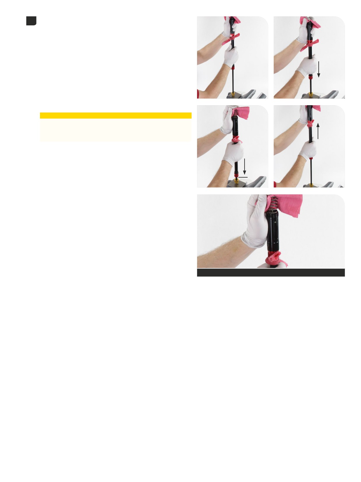
While still holding the IFP spring compressed, slowly compress the
6
damper until the rebound sealhead is even with the bleed line (A) on
the rebound damper shaft. During the bleed process, the rebound
damper must not be compressed further than the bleed line (A) on the
rebound damper shaft.
A small amount of oil should purge from the bleed hole in the IFP tube.
Lift the damper up slowly, while maintaining pressure on the IFP spring,
and allow the rebound damper to extend. Compressing the IFP will
apply opposing pressure in the damper to allow the rebound damper
to extend fully.
Repeat this process 2 mores times (3 total).
The IFP tube may contain a small amount of oil after oil is purged from
the bleed port. Pour out any remaining oil from the IFP tube into an oil
pan before installing the top cap.
⚠CAUTION
Oil may exit the cartridge tube bleed hole. Wear safety glasses
and keep your eyes and face away from the bleed hole when
compressing the rebound damper.
A
Purged oil
1
Damper Bleed - Charger 3 RC2
02
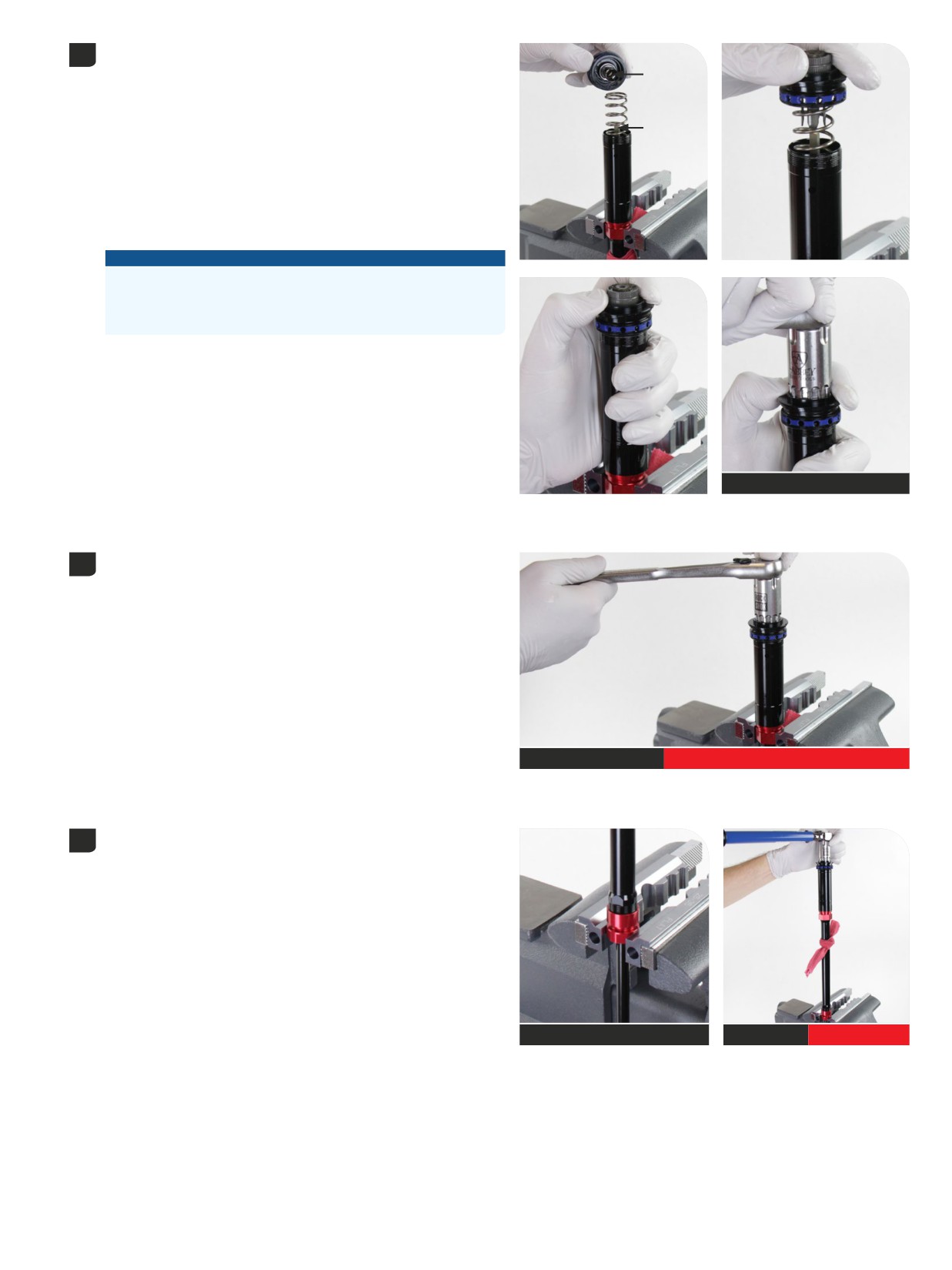
Clamp the red coupler in the vise.
7
Align the keyed end of the compression adjuster under the top cap (A),
A
with the (LSC) low speed compression damper adjuster tab (B).
While pushing down firmly and evenly, visually confirm the (LSC) low
speed compression adjuster tab engages the mating (LSC) low speed
B
compression damper adjuster tab.
Press the top cap down, compress the IFP spring, align the keyed
parts, and engage the top cap threads slowly when the keyed parts are
aligned and engaged.
Press down with the top cap tool and slowly thread the top cap onto
the cartridge tube.
NOTICE
The top cap threads will not engage if the keyed adjuster parts are
not aligned and engaged.
Do not cross-thread the top cap and IFP tube.
RockShox Top Cap Tool
When the threads are engaged properly, thread the top cap onto the
8
IFP tube and tighten to torque.
Top cap / Cassette tool
14 N∙m (125 in-lb)
Remove the damper from the vise.
9
With the rebound damper oriented downward, clamp the rebound
sealhead into the vise at the wrench flats.
Tighten the compression damper top cap to the specified torque.
Top cap /
Reverb Vise Blocks (flat)
14 N∙m (125 in-lb)
Cassette tool
Damper Bleed - Charger 3 RC2
103
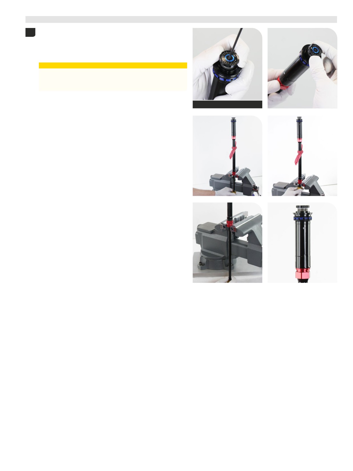
Test Compression
- Charger
3 RC2
Temporarily install the LSC adjuster knob onto the compression
1
adjuster. Install and tighten the retaining screw finger tight.
Rotate the (LSC) low speed compression adjuster clockwise until
it stops at the last detent, until it stops. This is the firmest LSC
compression setting.
⚠CAUTION
Oil may exit the cartridge tube bleed hole. Wear safety glasses
and keep your eyes and face away from the bleed hole when
compressing the rebound damper.
2.5 mm
During the damper test process, the rebound damper must not be
compressed further than the bleed line on the damper shaft.
Push the rebound damper into the cartridge tube slowly. Firm and
consistent resistance should be felt with no gaps in movement. Do not
push the rebound damper in further than the bleed line on the rebound
damper shaft.
A small amount of oil may purge from the bleed port.
Rotate the LSC compression adjuster counterclockwise to the full open
setting and repeat the compression test. Light consistent resistance
should be felt with no gaps in movement.
Cycle the rebound damper up and down with the compression adjuster
in the full open position, until oil no longer purges from the bleed port.
If gaps are felt during compression, repeat the oil fill and bleed
process. If the assembly process was successful, set the compression
damper to the open setting.
Remove the shop towel and wipe away any oil from the damper
assembly.
Remove the LSC adjuster knob when the test is complete.
1
T
04
est Compression - Charger 3 RC2
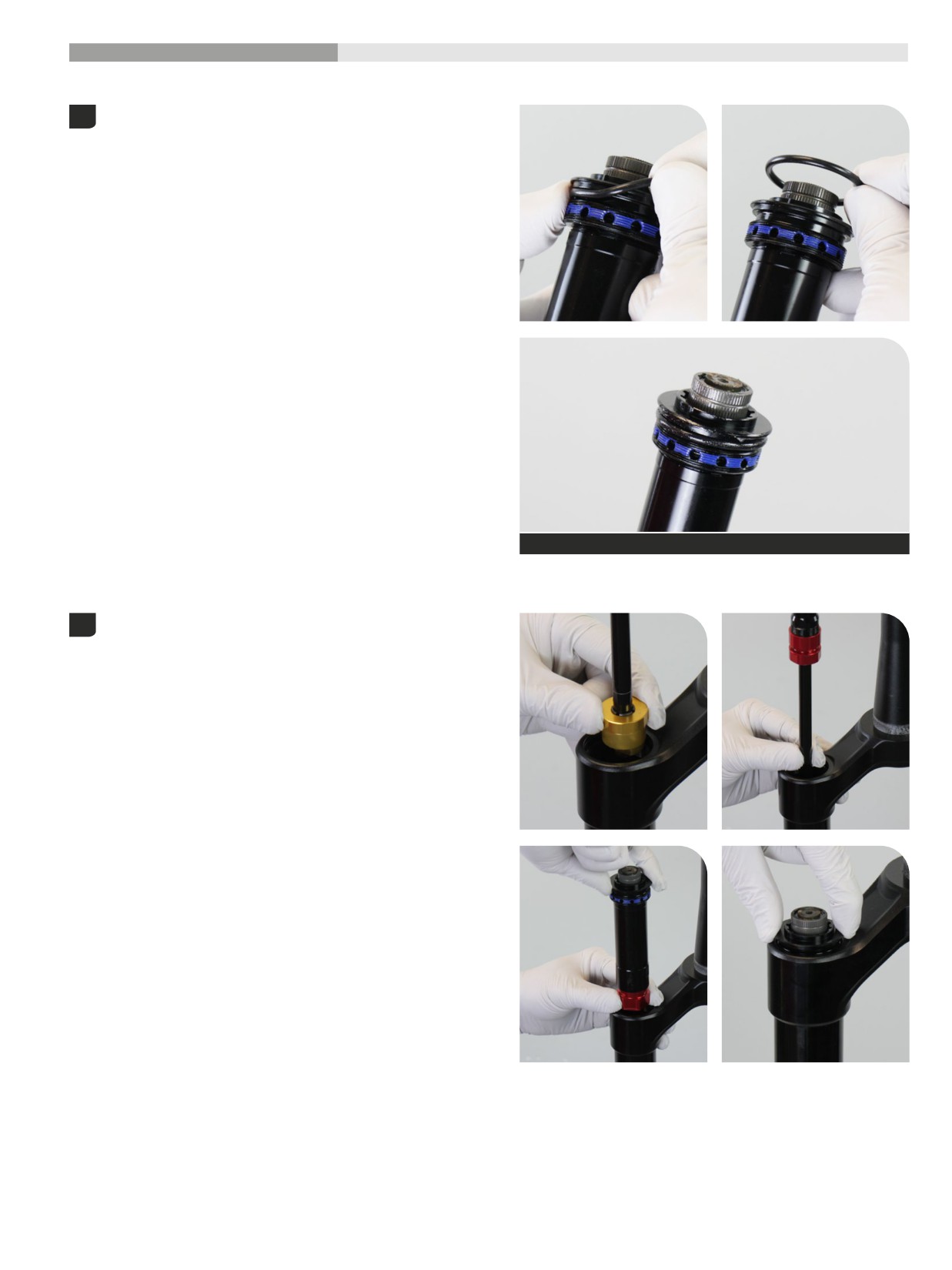
200 Hour Service
Damper Installation
- Charger
3 RC2
Upgrade - Charger 3 RC2 Damper assembly with ButterCups: Proceed to Step 2.
Remove the o-ring from the top cap.
1
Clean the top cap threads and o-ring groove.
Apply grease to a new top cap o-ring and install it.
SRAM Butter Grease
Install the damper assembly into the damper side upper tube. Use
2
your fingers to guide the damper and damper shaft into the upper tube
without scratching the shaft.
1
Damper Installation - Charger 3 RC2
05
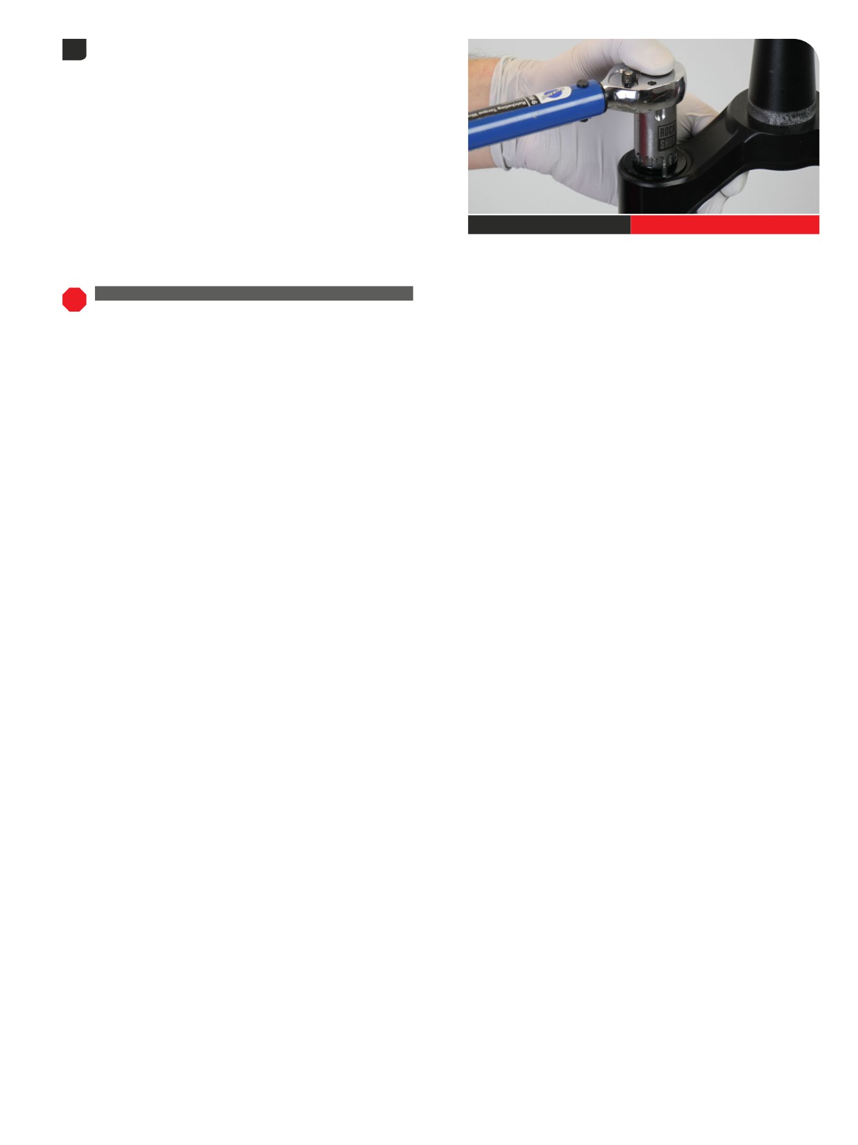
Thread the top cap into the upper tube and tighten it. Press down
3
firmly when tightening the top cap.
Top cap / Cassette tool
28 N∙m (250 in-lb)
UPGRADE - CHARGER 3 RC2 DAMPER WITH BUTTERCUPS
To continue with the upgrade damper installation process, proceed to
Controls
Installation - Charger 3 RC2.
1
Damper Installation - Charger 3 RC2
06
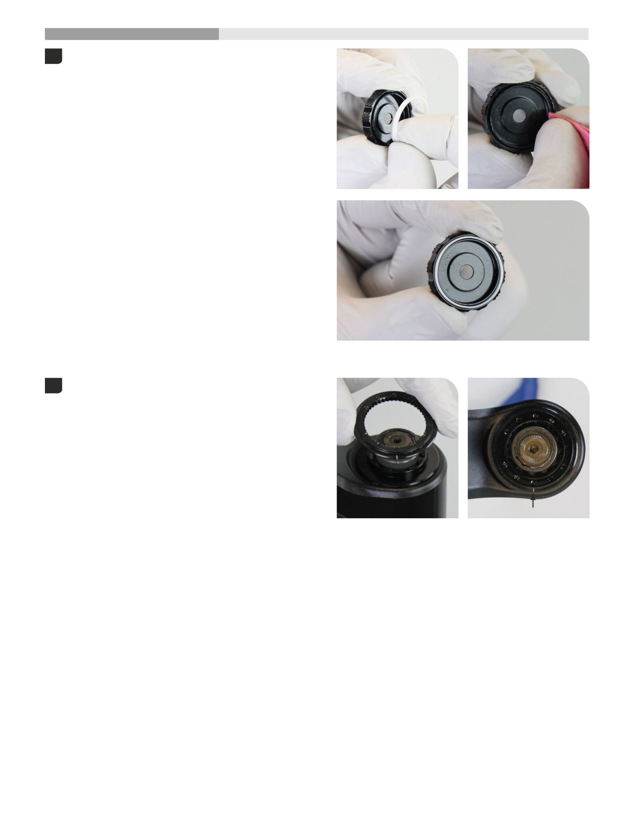
200 Hour Service
Controls Installation
- Charger
3 RC2
Remove the white ring from the LSC knob and discard it.
1
Clean the groove.
Install a new white ring.
Install the High Speed Compression (HSC) knob detent plate with
2
the alignment tick mark (A) oriented to the back of the crown,
perpendicular to the steerer tube.
A
1
Controls Installation - Charger 3 RC2
07
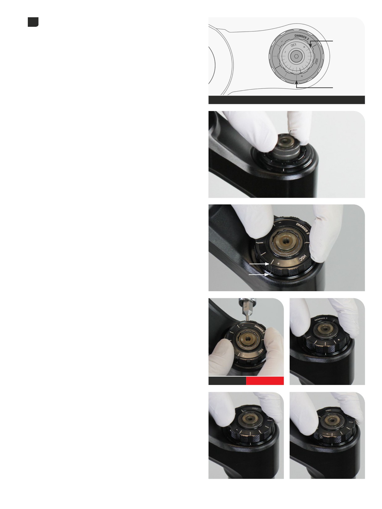
The High Speed Compression (HSC) and Low Speed Compression
3
Front
(LSC) adjuster knobs must be installed in the full clockwise/closed
positions with the alignment marks oriented as indicated.
LSC
HSC
Back
HSC - full clockwise/closed
LSC - full clockwise/closed
Rotate the large (HSC) High Speed Compression adjuster cam
clockwise, by hand, until it stops.
Install the HSC (LARGE) knob and align the (+) tick mark (A) with the
alignment tick mark (B) on the detent plate at the back of the crown.
Refer to the diagram above.
A
B
Tighten the HSC knob set screw.
Check function - Rotate the knob counterclockwise and confirm each
detent tick mark aligns with the tick mark on the detent plate.
2.5 mm
0.28 N·m (2.5 in-lb)
Controls Installation - Charger 3 RC2
108
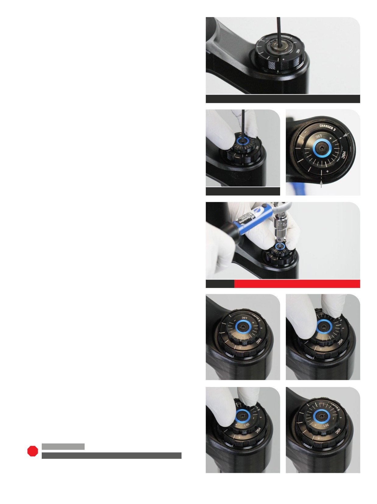
Rotate the LSC adjuster cam full clockwise, with a 2.5 mm hex wrench,
until it stops.
2.5 mm
Install and position the LSC adjuster knob and position the knob with
the LSC (A) and HSC (B) alignment marks as pictured.
A
2.5 mm
B
Hold the LSC adjuster knob in place and tighten the retaining screw.
2.5 mm
0.56 N·m (5 in-lb)
Check function. Rotate the LSC (SMALL) knob counterclockwise and
confirm each detent tick mark aligns with the tick mark on the HSC
(LARGE) knob.
200 Hour Service Continue with Lower Leg Installation.
UPGRADE - CHARGER 3 RC2 DAMPER WITH BUTTERCUPS
To
complete the damper upgrade installation process, proceed to Lower
Leg Installation.
1
Controls Installation - Charger 3 RC2
09
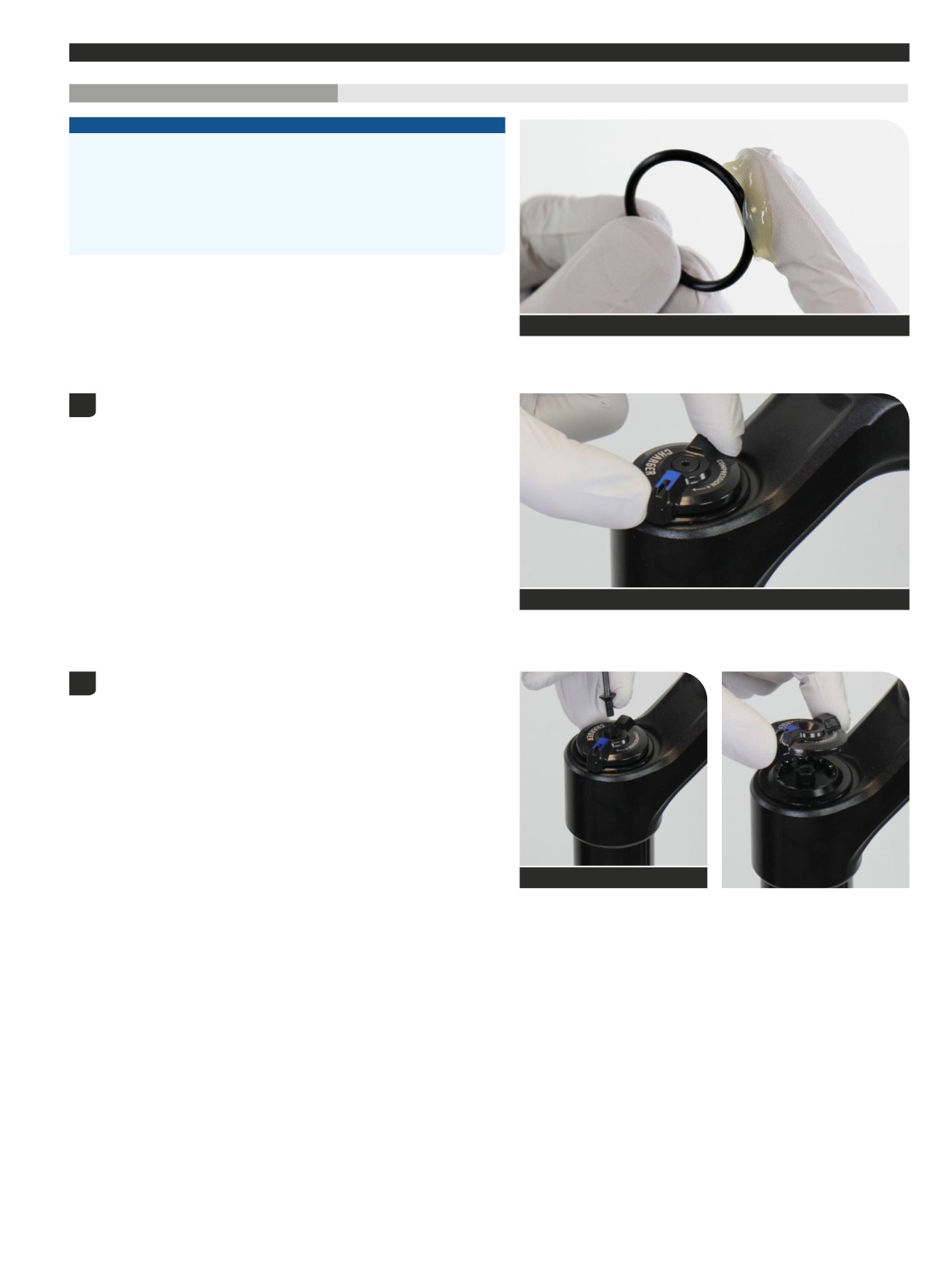
Damper Service
- Charger RC
200 Hour Service
Controls Removal
- Charger RC
NOTICE
Inspect each part for scratches. Do not scratch any sealing surfaces when
servicing your suspension. Scratches can cause leaks.
When replacing seals and o-rings, use your fingers or a pick to remove the
seal or o-ring. Spray RockShox Suspension Cleaner or isopropyl alcohol
onto each part and clean with a clean lint-free shop towel.
Apply SRAM Butter Grease to the new seals and o-rings.
SRAM Butter Grease
The compression damper must be in the full open position in order to
1
perform bleed procedure.
Turn the compression adjuster knob counterclockwise, to the full open
position, until it stop.
Charger RC
Remove the knob retaining screw and remove the adjuster knob.
2
2.5 mm
Damper Service - Charger RC
110
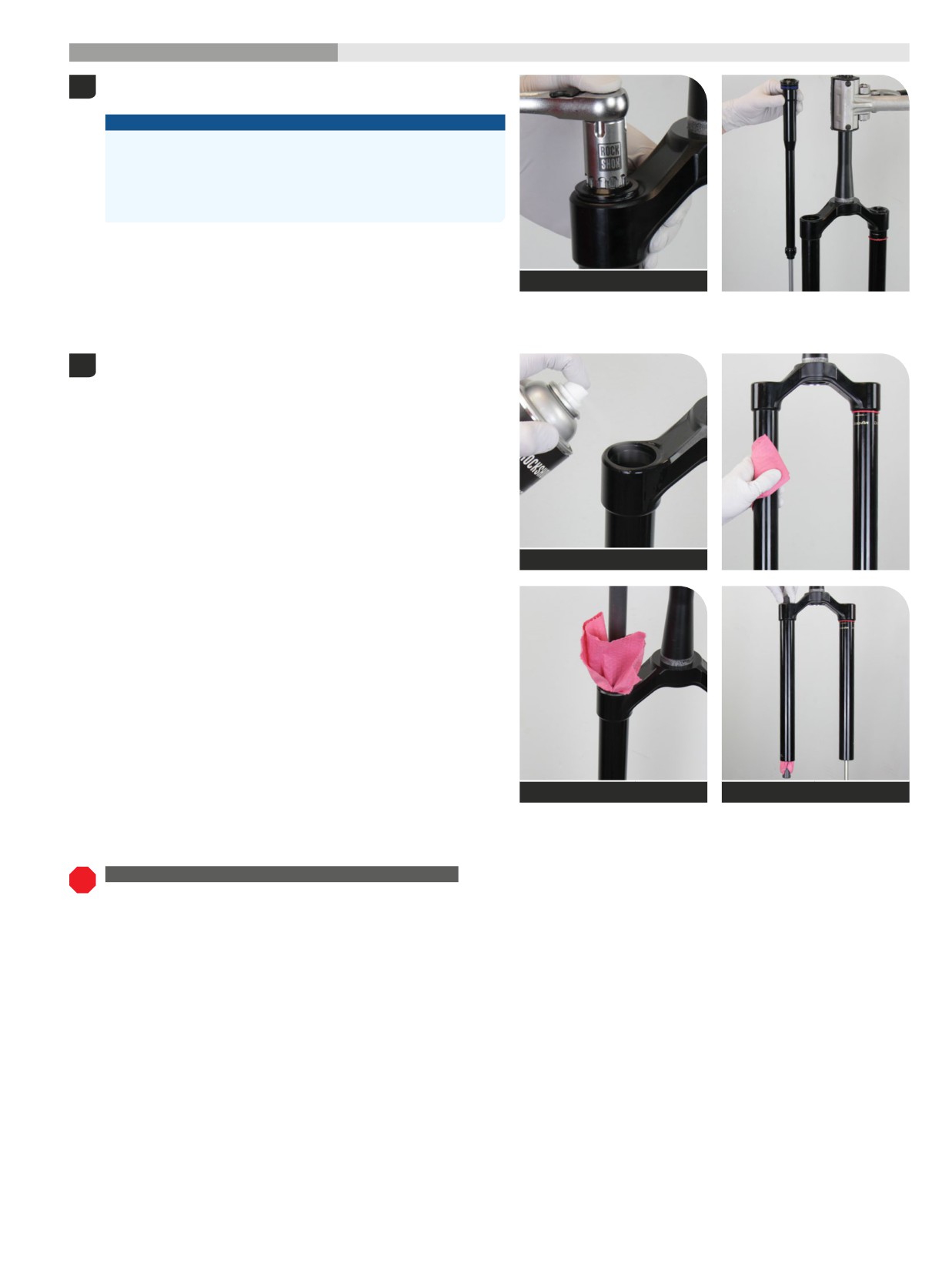
200 Hour Service
Damper Removal
- Charger RC
Unthread the damper top cap and remove the damper assembly. Press
1
down firmly when loosening the top cap.
NOTICE
The fork top caps are tightened to a high torque value. Ensure the
fork is held securely in the bicycle stand. To avoid damage to the
top cap, press the top cap / cassette tool squarely and firmly down
when loosening. Use a socket wrench with a long handle for extra
leverage.
Top cap / Cassette tool
Clean the inside and outside of the upper tube.
2
Clean the upper tube threads.
RockShox Suspension Cleaner
Dowel
Dowel
UPGRADE - CHARGER 3 RC2 DAMPER WITH BUTTERCUPS
Select: To install a Charger 3 RC2 damper assembly with pre-installed
ButterCups, proceed to Damper Installation - Charger 3 RC2.
Damper Removal - Charger RC
111
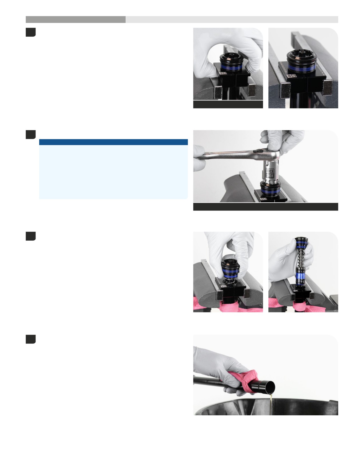
200 Hour Service
Damper Service
- Charger RC
Clamp the cartridge tube in a vise with Charger Vise Blocks.
1
Charger Vise Blocks
Unthread the top cap from the tube.
2
NOTICE
The cartridge tube and vise blocks must be dry and free of oil to
provide enough grip to unthread the top cap. If the cartridge tube
slips, clean and dry the tube and vise blocks.
The fork top caps are tightened to a high torque value. Ensure the
fork is held securely in the bicycle stand. To avoid damage to the
top cap, press the top cap / cassette tool squarely and firmly down
when loosening. Use a socket wrench with a long handle for extra
leverage.
Top cap / Cassette tool or 24 mm
Wrap a shop towel around the cartridge tube under the top cap to
3
absorb oil.
Carefully remove the compression damper.
Remove the cartridge tube and rebound damper assembly from the
4
vise and pour the oil into an oil pan.
Clean the exterior of the cartridge tube.
Damper Service - Charger RC
112
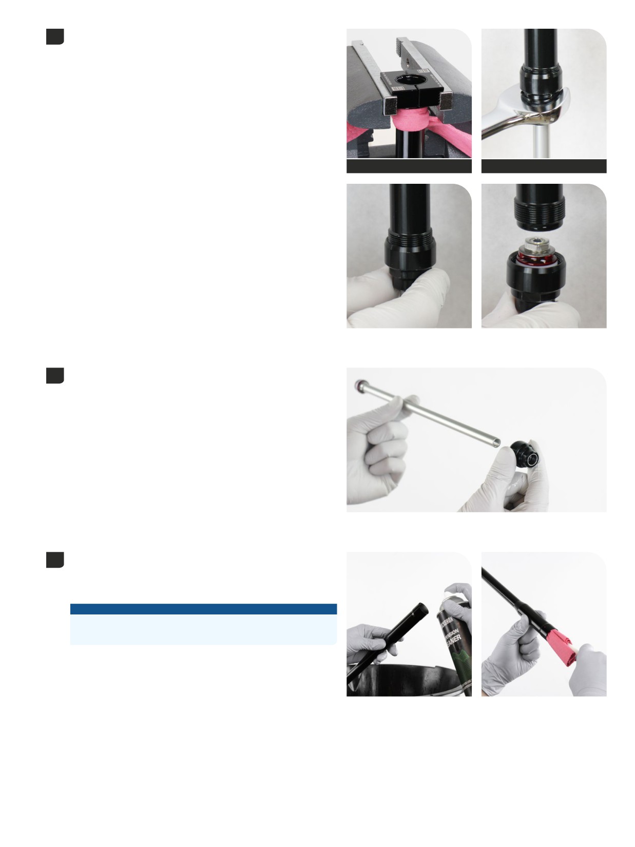
Clamp the cartridge tube into a vise with Charger Vise Blocks.
5
Remove the rebound damper sealhead and rebound damper.
Remove the cartridge tube from the vise.
Charger Vise Blocks
19 mm
Remove the sealhead from the rebound damper shaft.
6
Discard the sealhead.
Spray RockShox Suspension Cleaner or isopropyl alcohol into the
7
cartridge tube and clean the inside of the tube with a clean shop towel
and a thin dowel (≤16 mm diameter).
Inspect the inside of the cartridge tube for scratches.
NOTICE
Scratches can cause oil to leak. Replace the cartridge tube if a
scratch is visible.
Damper Service - Charger RC
113
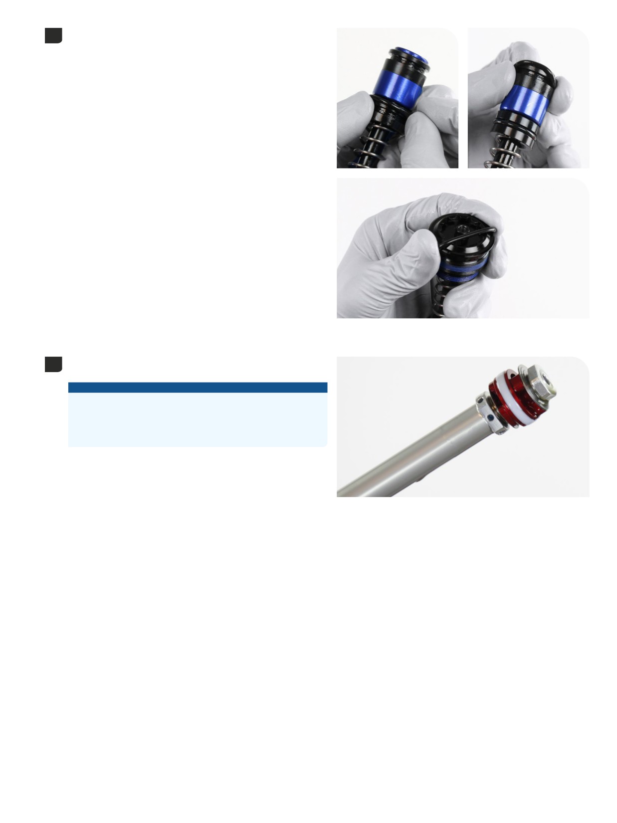
Remove the o-rings from the compression damper and discard them.
8
Apply grease to new o-rings and install them.
The solid band glide ring is not removable and only requires cleaning.
9
Do not remove.
NOTICE
Do not remove the solid band glide ring. The solid band glide ring is
not serviceable. Removal of the solid band glide ring will require a
new damper assembly.
The color of the solid band glide ring may vary.
Damper Service - Charger RC
114
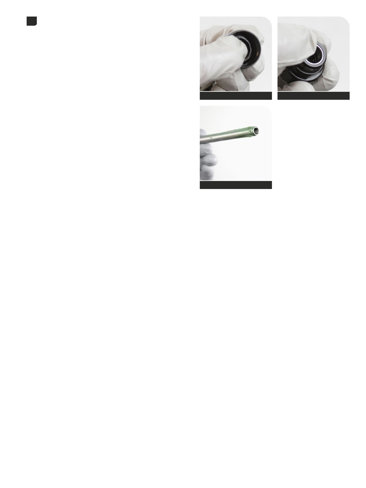
Apply grease to the inner seal and bushing in the new rebound damper
10
sealhead.
Apply grease to the end of the rebound damper shaft.
SRAM Butter Grease
SRAM Butter Grease
SRAM Butter Grease
Damper Service - Charger RC
115
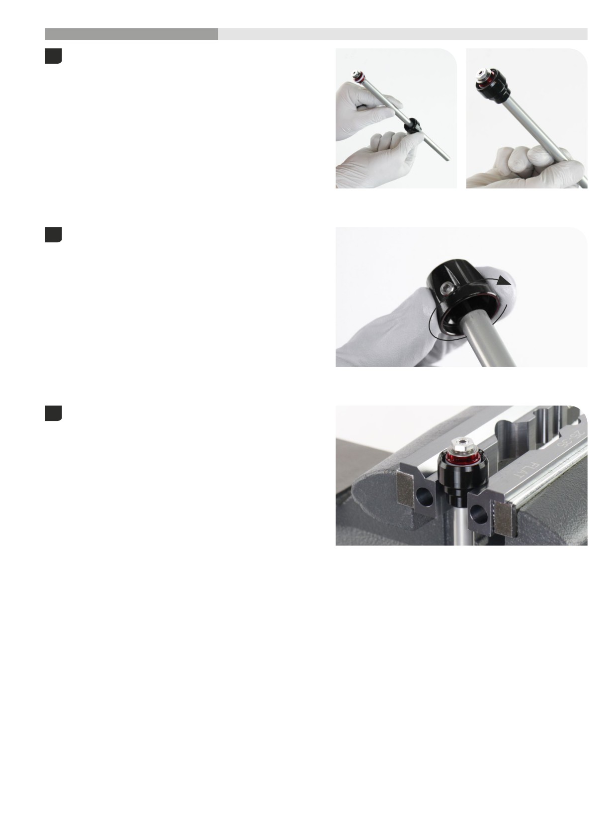
200 Hour Service
Damper Assembly
- Charger RC
Insert the rebound damper shaft into the recessed end of the sealhead.
1
Slide the sealhead toward the piston.
Insert the rebound adjuster knob into the rebound damper shaft and
2
rotate it counter clockwise until it stops. This is the full open position.
Clamp the sealhead into the vise.
3
1
Damper Assembly - Charger RC
16
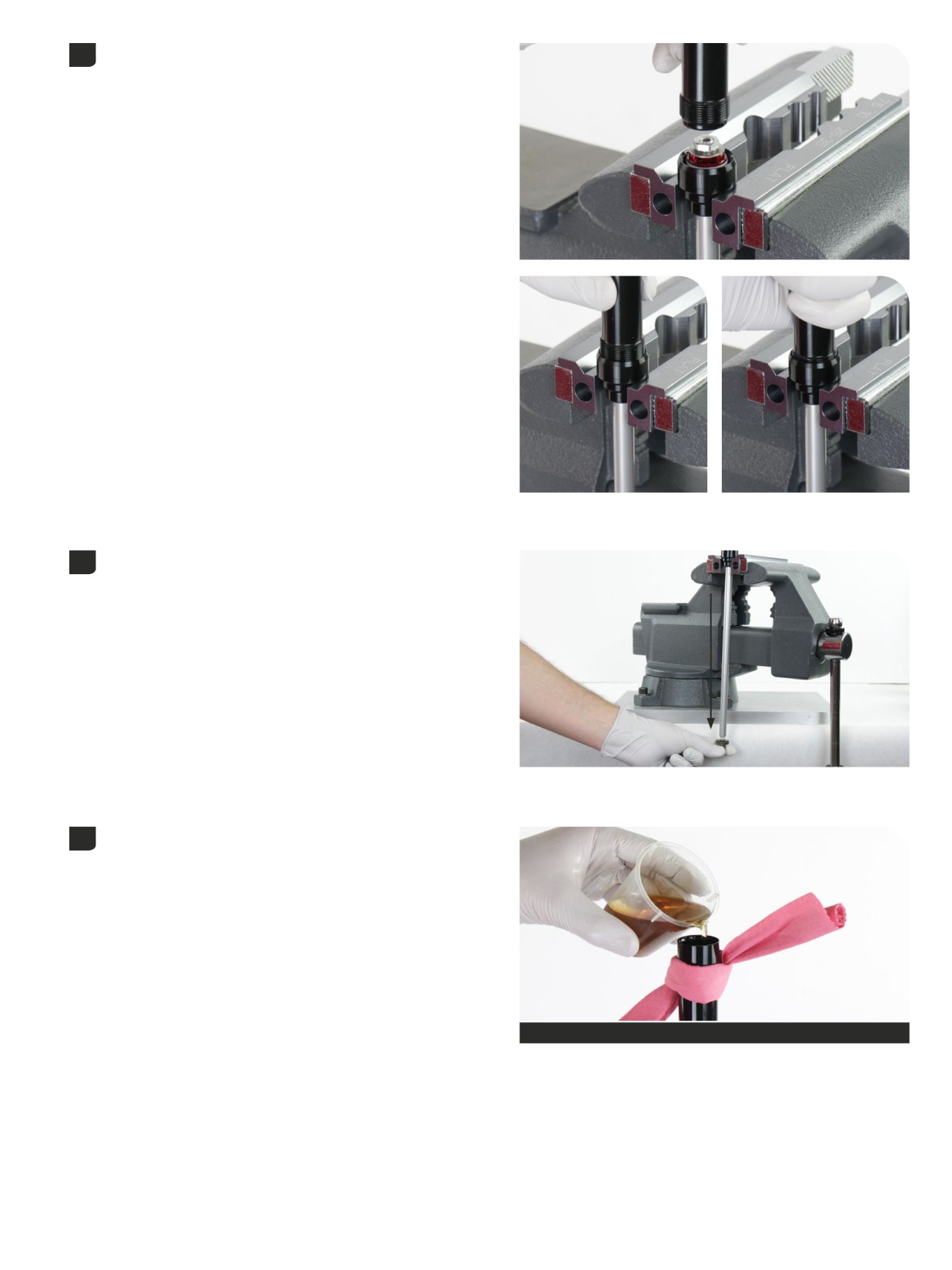
Insert the rebound damper shaft into the cartridge tube. Tighten the
4
sealhead hand tight.
Pull the damper shaft to full extension.
5
Thread a bottom bolt into the rebound damper shaft.
Secure a shop towel around the cartridge tube to absorb oil.
6
Pour 3wt suspension oil into the tube until it is approximately half full.
Maxima PLUSH 3wt suspension oil
Damper Assembly - Charger RC
117

Slowly cycle the rebound damper in and out half way to remove air
7
bubbles trapped under the rebound damper piston.
Stop when no bubbles are visible in the oil.
Secure a plastic cable tie around the shaft A (mm) from the end of the
8
shaft.
Push the rebound damper into the cartridge tube until there is (A) mm
(length) of shaft extended. Do not push the damper into the tube any
further.
Fork
Fork travel (mm)
A (mm)
120
A
Pike
130
92
140
See table
140
Lyrik
150
104
160
150
160
ZEB
170
100
180
190
Pour 3wt suspension oil into the tube until the oil is just below the
9
(A) bleed holes.
A
Maxima PLUSH 3wt suspension oil
1
Damper Assembly - Charger RC
18
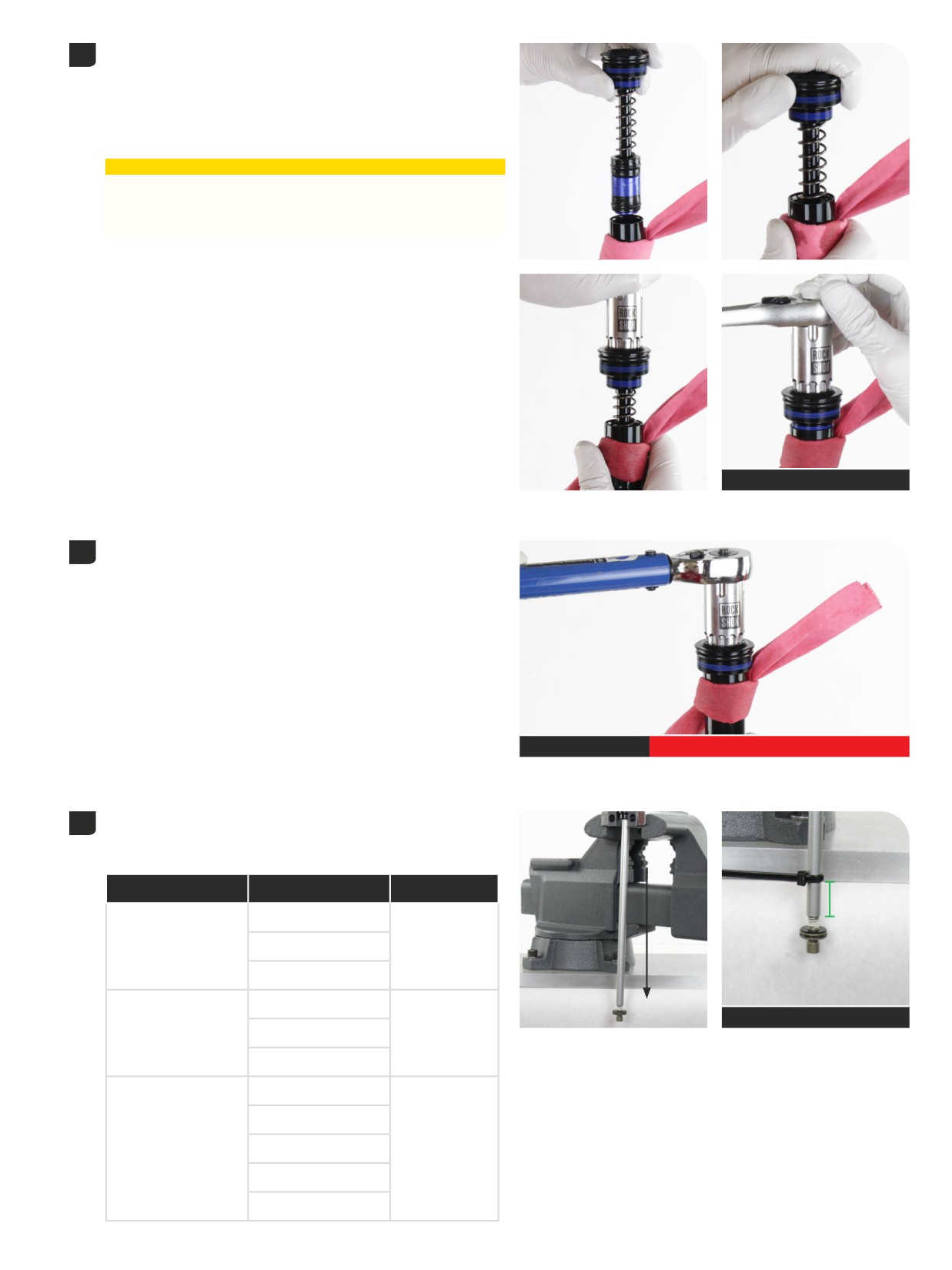
Cover the bleed holes with the shop towel.
10
Insert the compression damper into the cartridge tube and slowly
push it into the tube. The rebound damper will slowly extend as the
compression damper is installed; this is normal.
Firmly push the compression damper down, into the cartridge tube.
Thread the top cap into the tube.
⚠CAUTION
Oil will exit the cartridge tube bleed hole(s). Wear safety glasses
and keep your eyes and face away from the bleed hole(s) when
compressing and installing the compression damper.
Top cap / Cassette tool
Tighten the top cap to the specified torque. Press down firmly when
11
tightening the top cap.
The rebound damper sealhead will be tightened onto the other end of
the cartridge tube simultaneously.
Top cap / Cassette tool
9 N·m (80 in-lb)
Pull the rebound damper to full extension.
12
Secure a plastic cable tie around the shaft A (mm) from the end of the
shaft.
Fork
Fork travel (mm)
A (mm)
A
120
Pike
130
25.5
140
140
See table
Lyrik
150
23.5
160
150
160
ZEB
170
19
180
190
Damper Assembly - Charger RC
119
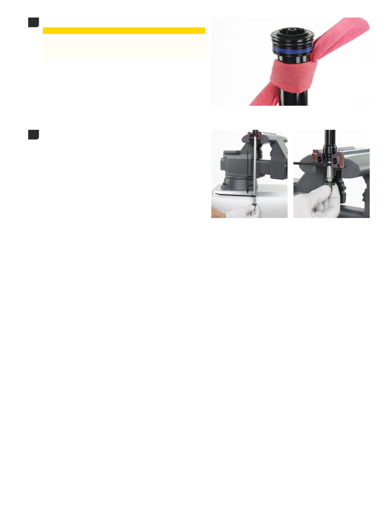
Cover the bleed hole(s) with the secured towel.
13
⚠CAUTION
Oil will exit the cartridge tube bleed hole(s). Wear safety glasses
and keep your eyes and face away from the bleed hole(s) when
compressing the rebound damper.
Slowly push the rebound damper shaft into the tube until the cable
14
tie contacts the sealhead, then stop. Do not push the damper in any
further.
Slowly, pull the rebound shaft out to full extension.
Repeat 3-5 more times. This will allow any excess oil and air to escape
from the system.
Remove the bottom bolt. Remove the damper assembly from the vise
and clean it with a shop towel.
Do not remove the cable tie.
1
Damper Assembly - Charger RC
20
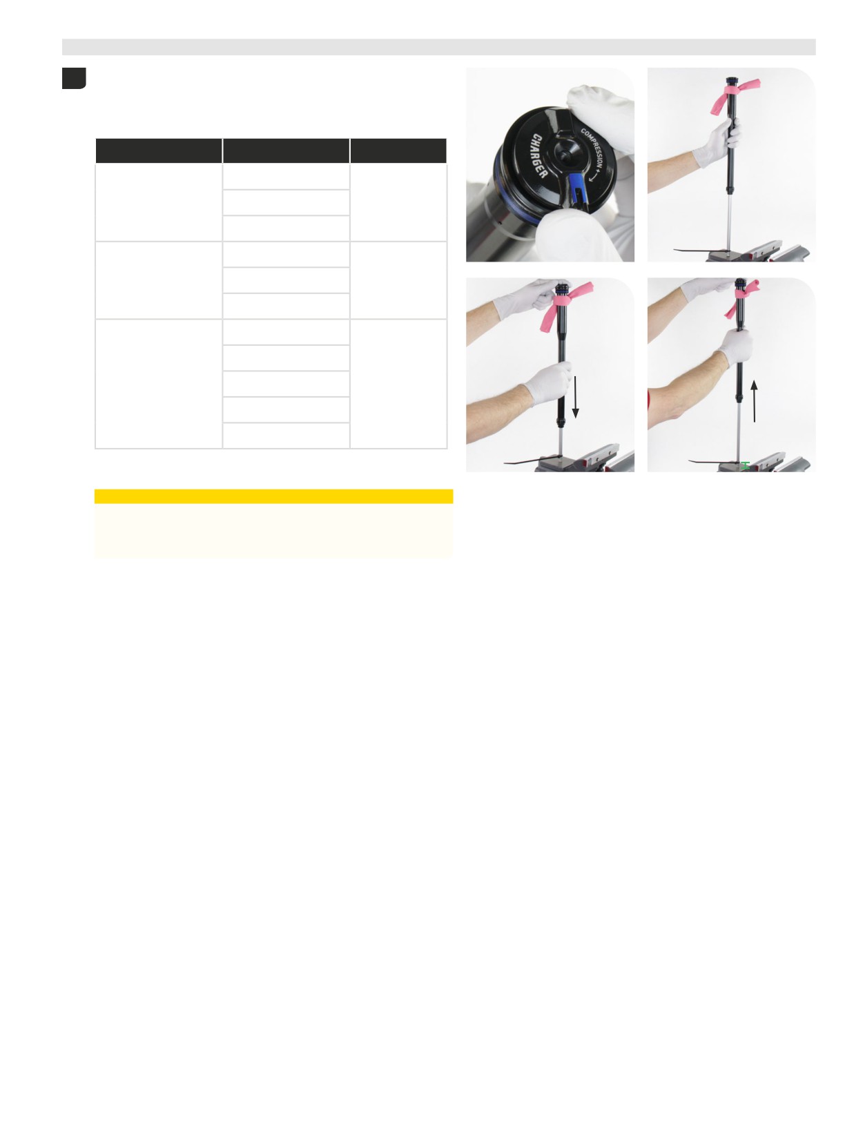
Test Compression
- Charger RC
Use the adjuster knob to rotate the compression cam clockwise, until it
1
stops, to the firm position.
The cable tie must be (A) mm from the end of the shaft. Do not
compress the rebound damper further than this point.
Fork
Fork travel (mm)
A (mm)
120
Pike
130
25.5
140
140
Lyrik
150
23.5
160
150
160
ZEB
170
19
180
190
A
Cover the oil bleed hole(s) with the secured towel.
⚠CAUTION
Oil will exit the cartridge tube bleed hole(s). Wear safety glasses
and keep your eyes and face away from the bleed hole(s) when
compressing the rebound damper.
Push down on the damper assembly slowly to test the firmest
compression setting. Firm and consistent resistance should be felt with
no gaps in movement.
Rotate the compression damper to the open setting and repeat the
compression test. Light consistent resistence should be felt with no
gaps in movement.
If gaps are felt during compression, repeat the oil fill and bleed
process. If the assembly process was successful, set the compression
damper to the open setting and remove the cable tie.
1
T
21
est Compression - Charger RC
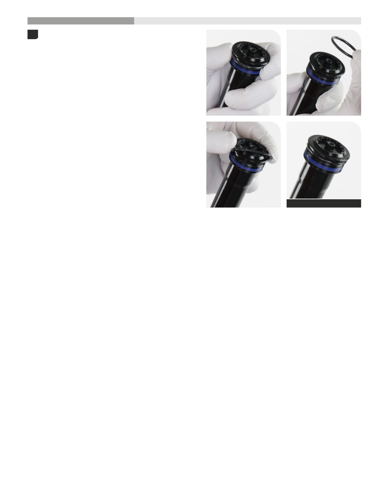
200 Hour Service
Damper Installation
- Charger RC
Remove the o-ring from the top cap.
1
Clean the top cap threads and o-ring groove.
Apply grease to a new o-ring and install it.
SRAM Butter Grease
1
Damper Installation - Charger RC
22
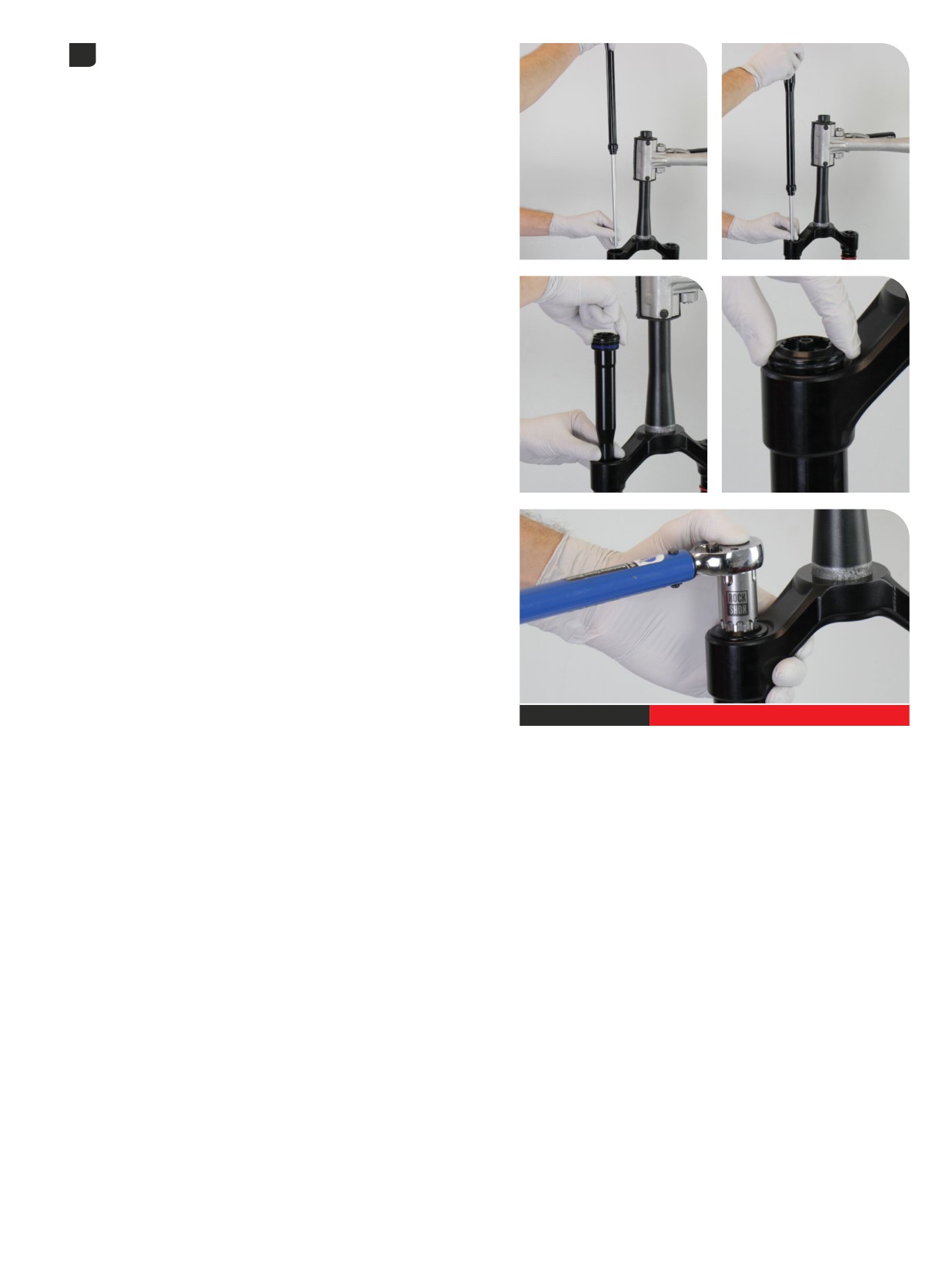
Install the damper assembly into the damper side upper tube. Use
2
your fingers to guide the damper and damper shaft into the upper tube
without scratching the shaft.
Thread the top cap into the upper tube and tighten it. Press down
firmly when tightening the top cap.
Top cap / Cassette tool
28 N·m (250 in-lb)
Damper Installation - Charger RC
123
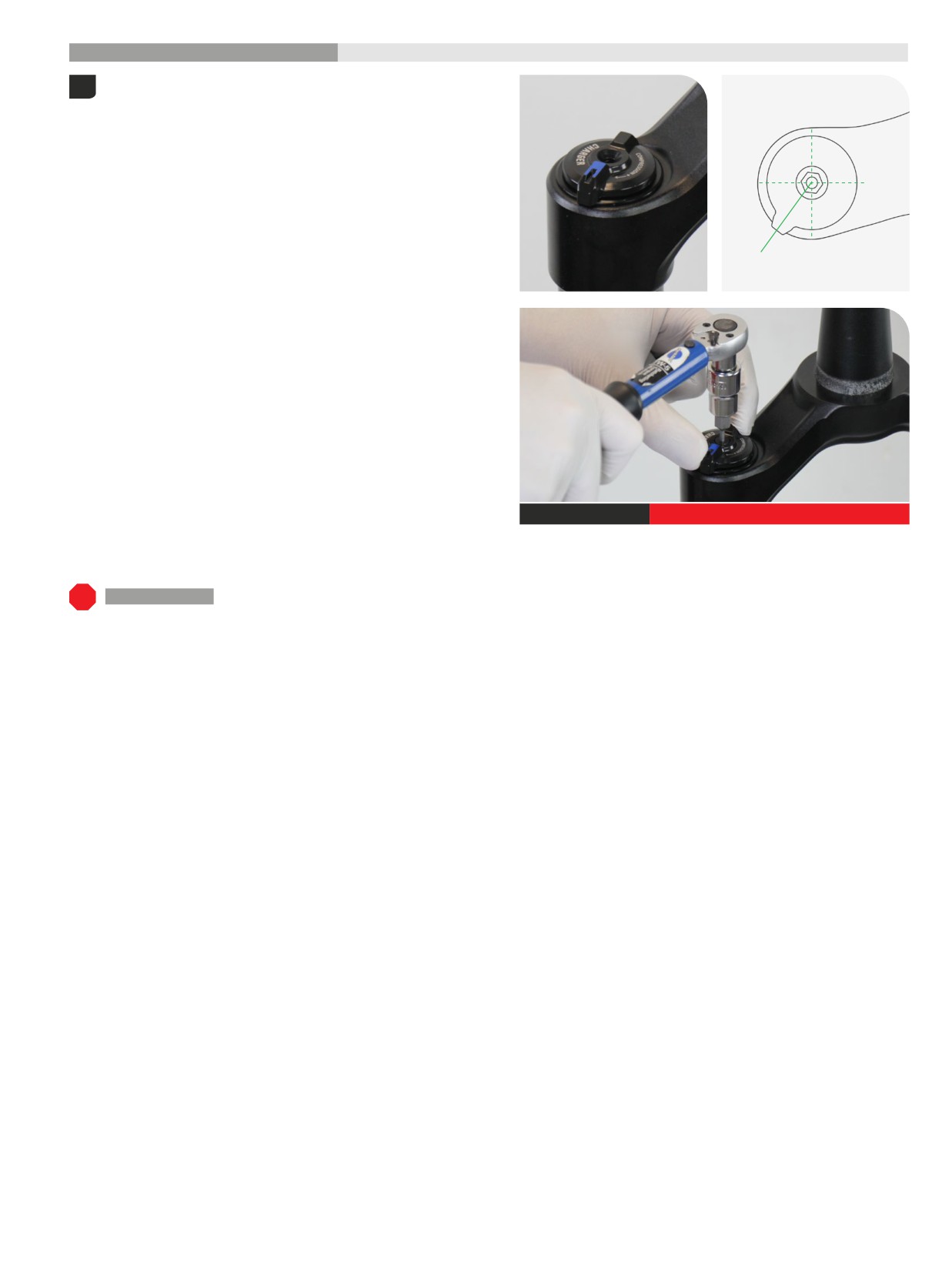
200 Hour Service
Controls Installation
- Charger RC
Install the adjuster knob with the tab in the 7-8 o'clock, unlocked,
1
position.
Rear
Front
Install and tighten the retaining screw.
2.5 mm
1.35 N·m (12 in-lb)
200 Hour Service Continue with Lower Leg Installation.
1
Controls Installation - Charger RC
24
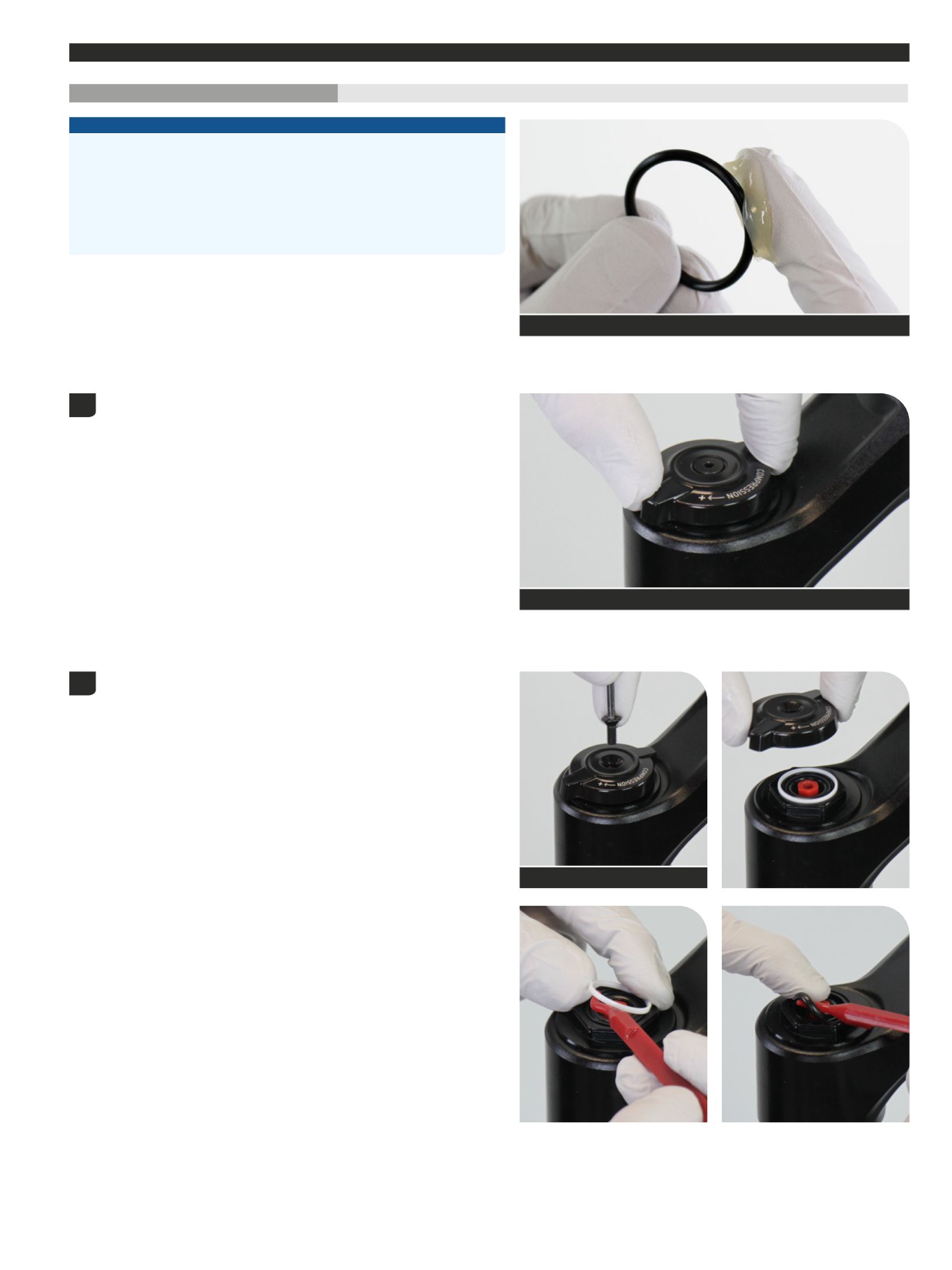
Damper Service
- Rush RC
200 Hour Service
Controls Removal
- Rush RC
NOTICE
Inspect each part for scratches. Do not scratch any sealing surfaces when
servicing your suspension. Scratches can cause leaks.
When replacing seals and o-rings, use your fingers or a pick to remove the
seal or o-ring. Spray RockShox Suspension Cleaner or isopropyl alcohol
onto each part and clean with a clean lint-free shop towel.
Apply SRAM Butter Grease to the new seals and o-rings.
SRAM Butter Grease
The compression damper must be in the full open position in order to
1
perform the bleed procedure.
Turn the compression adjuster knob counterclockwise, to the full open
position, until it stops.
Charger RC
Remove the retaining screw and remove the knob.
2
Remove the glide ring and o-ring. Clean the top cap grooves.
2.5 mm
1
Damper Service - Rush RC
25
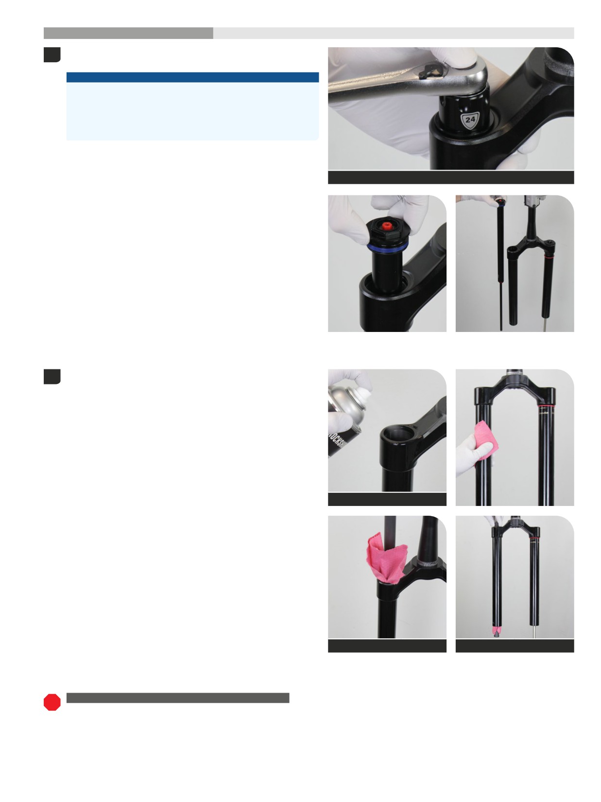
200 Hour Service
Damper Removal
- Rush RC
Unthread the damper top cap and remove the damper assembly. Press
1
down firmly when loosening the top cap.
NOTICE
The fork top caps are tightened to a high torque value. Ensure the
fork is held securely in the bicycle stand. To avoid damage to the
top cap, press the top cap / cassette tool squarely and firmly down
when loosening. Use a socket wrench with a long handle for extra
leverage.
Top cap / Cassette tool
Clean the inside and outside of the upper tube.
2
Clean the upper tube threads.
RockShox Suspension Cleaner
Dowel
Dowel
UPGRADE - CHARGER 3 RC2 DAMPER WITH BUTTERCUPS
Base: To install a Charger 3 RC2 damper assembly with pre-installed
ButterCups, proceed to Damper Installation - Charger 3 RC2.
1
Damper Removal - Rush RC
26
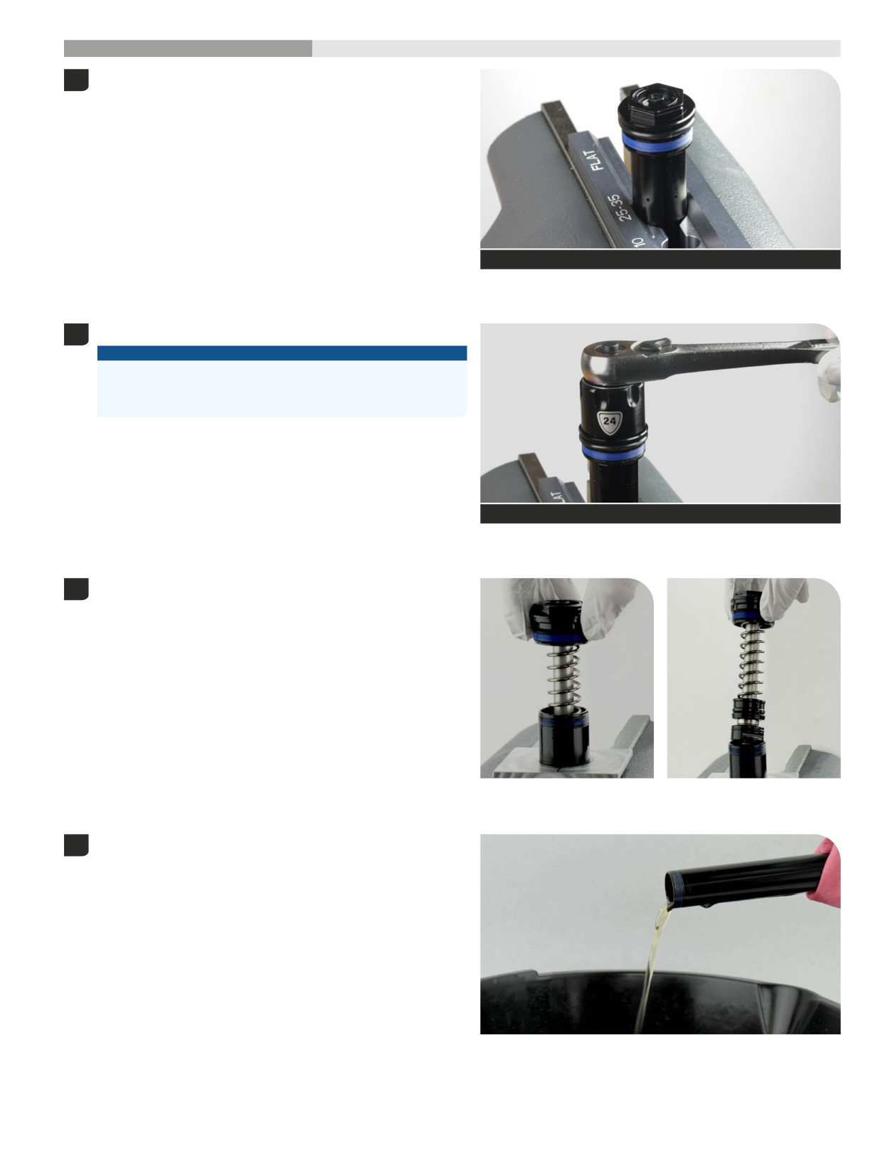
200 Hour Service
Damper Service
- Rush RC
Clamp the cartridge tube in a vise with Reverb Vise Blocks.
1
Reverb Vise Blocks (25 - 35 mm)
Unthread the top cap from the tube.
2
NOTICE
The cartridge tube and vise blocks must be dry and free of oil to
provide enough grip to unthread the top cap. If the cartridge tube
slips, clean and dry the tube and vise blocks.
24 mm
Wrap a shop towel around the cartridge tube under the top cap to
3
absorb oil.
Carefully remove the compression damper.
Remove the cartridge tube and rebound damper assembly from the
4
vise and pour the oil into an oil pan.
Clean the exterior of the cartridge tube.
1
Damper Service - Rush RC
27
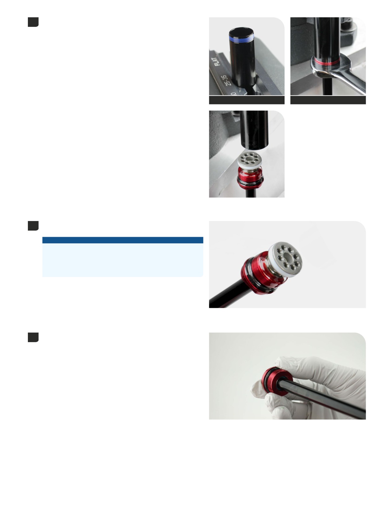
Clamp the cartridge tube into a vise with Reverb Vise Blocks.
5
Unthread and remove the rebound damper assembly.
Reverb Vise Blocks (25-35 mm)
Adjustable or 19 mm open end wrench
The solid band glide ring is not removable and only requires cleaning.
6
Do not remove.
NOTICE
Do not remove the solid band glide ring. The solid band glide ring is
not serviceable. Removal of the solid band glide ring will require a
new damper assembly.
The color of the solid band glide ring may vary.
Remove the sealhead from the rebound damper shaft.
7
Discard the sealhead.
1
Damper Service - Rush RC
28
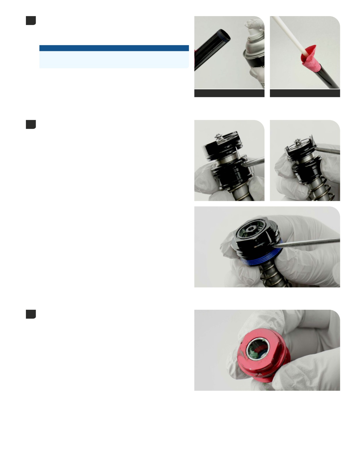
Spray RockShox Suspension Cleaner or isopropyl alcohol into the
8
cartridge tube and clean the inside of the tube with a clean shop towel
and a thin dowel (≤16 mm diameter).
Inspect the inside of the cartridge tube for scratches.
NOTICE
Scratches can cause oil to leak. Replace the cartridge tube if a
scratch is visible.
RockShox Suspension Cleaner or
Dowel
isopropyl alcohol
Remove the o-rings from the compression damper and discard them.
9
Apply grease to new o-rings and install them.
Apply grease to the inner seal and bushing in the new rebound damper
10
sealhead.
1
Damper Service - Rush RC
29
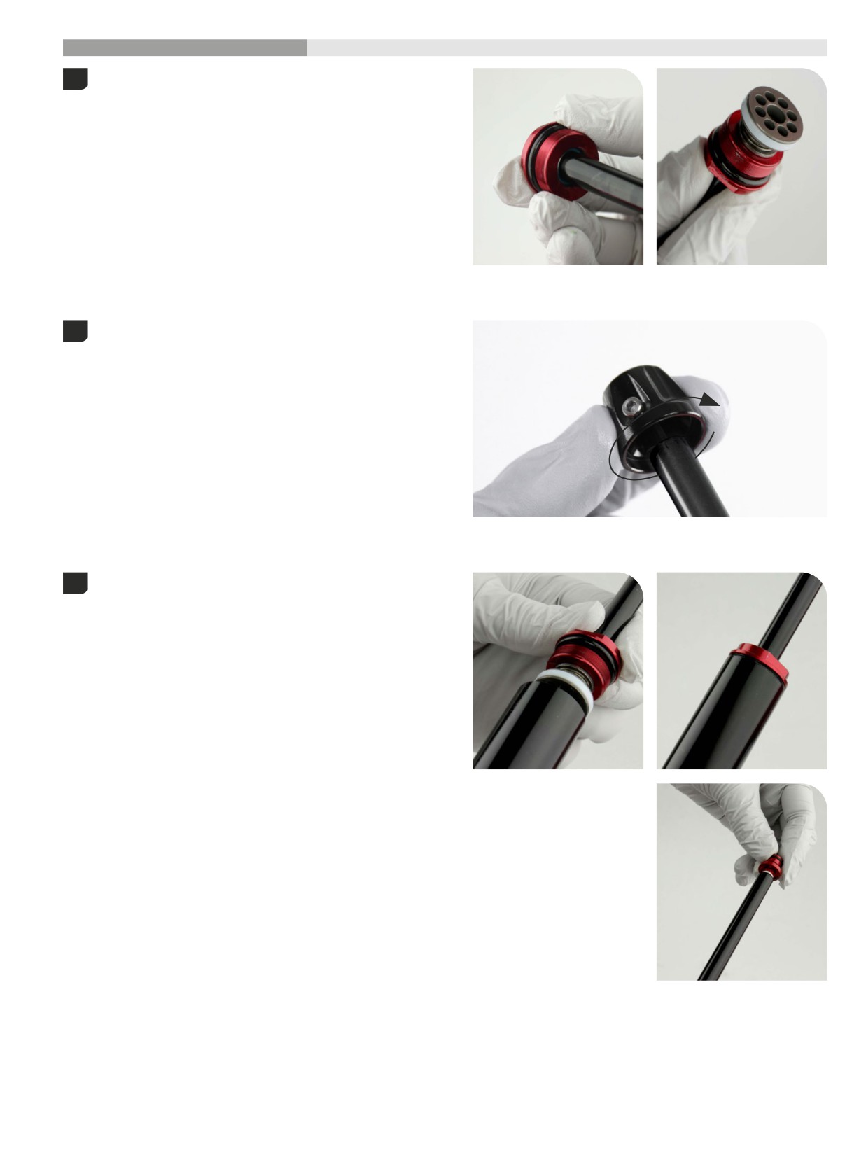
200 Hour Service
Damper Assembly
- Rush RC
Apply grease to the rebound damper shaft. Insert the rebound damper
1
shaft into the recessed end of the sealhead.
Slide the sealhead toward the piston.
Insert the rebound adjuster knob into the rebound damper and rotate
2
it counterclockwise 16 clicks from the closed position. This is the full
open position.
Thread the sealhead into the cartridge tube hand tight.
3
Thread the bottom bolt into the rebound damper shaft.
Damper Assembly - Rush RC
130
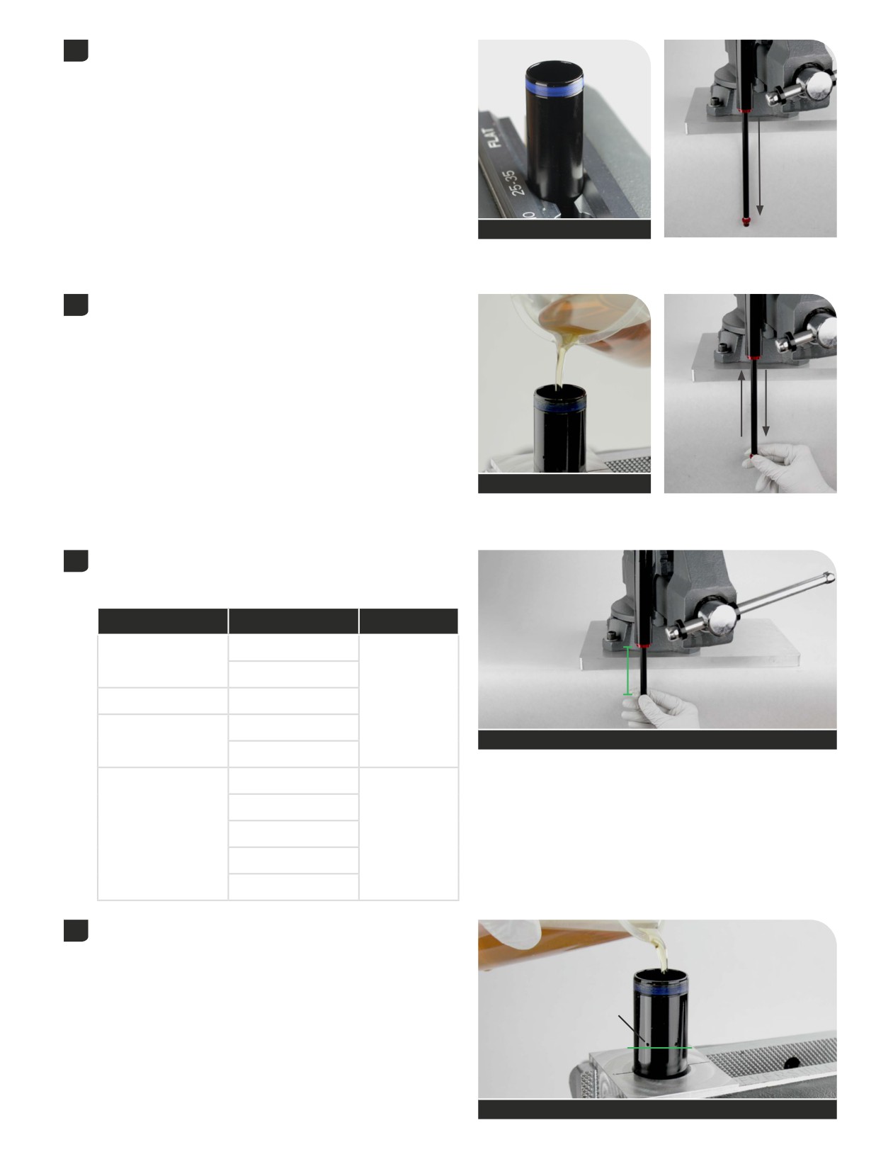
Clamp the cartridge tube into a vise with Reverb Vise Blocks. Pull the
4
damper shaft to full extension.
Reverb Vise Blocks
Pour Maxima PLUSH 3wt suspension oil into the tube until it is almost
5
half full. Slowly cycle the rebound damper shaft in and out half way to
remove air bubbles trapped under the rebound damper piston. Stop
when no bubbles are visible in the oil.
Maxima PLUSH 3wt suspension oil
Push the rebound damper into the cartridge tube until the rebound
6
shaft is at the (A mm) measurement.
Do not push the rebound damper into the tube any further.
Fork
Fork travel (mm)
A (mm)
120
Pike
130
A
Pike / Lyrik
140
70
150
Lyrik
See table
160
150
160
ZEB
170
94
180
190
Pour Maxima PLUSH 3wt suspension oil into the tube until the oil is just
7
below the bleed holes (A).
A
Maxima PLUSH 3wt suspension oil
Damper Assembly - Rush RC
131
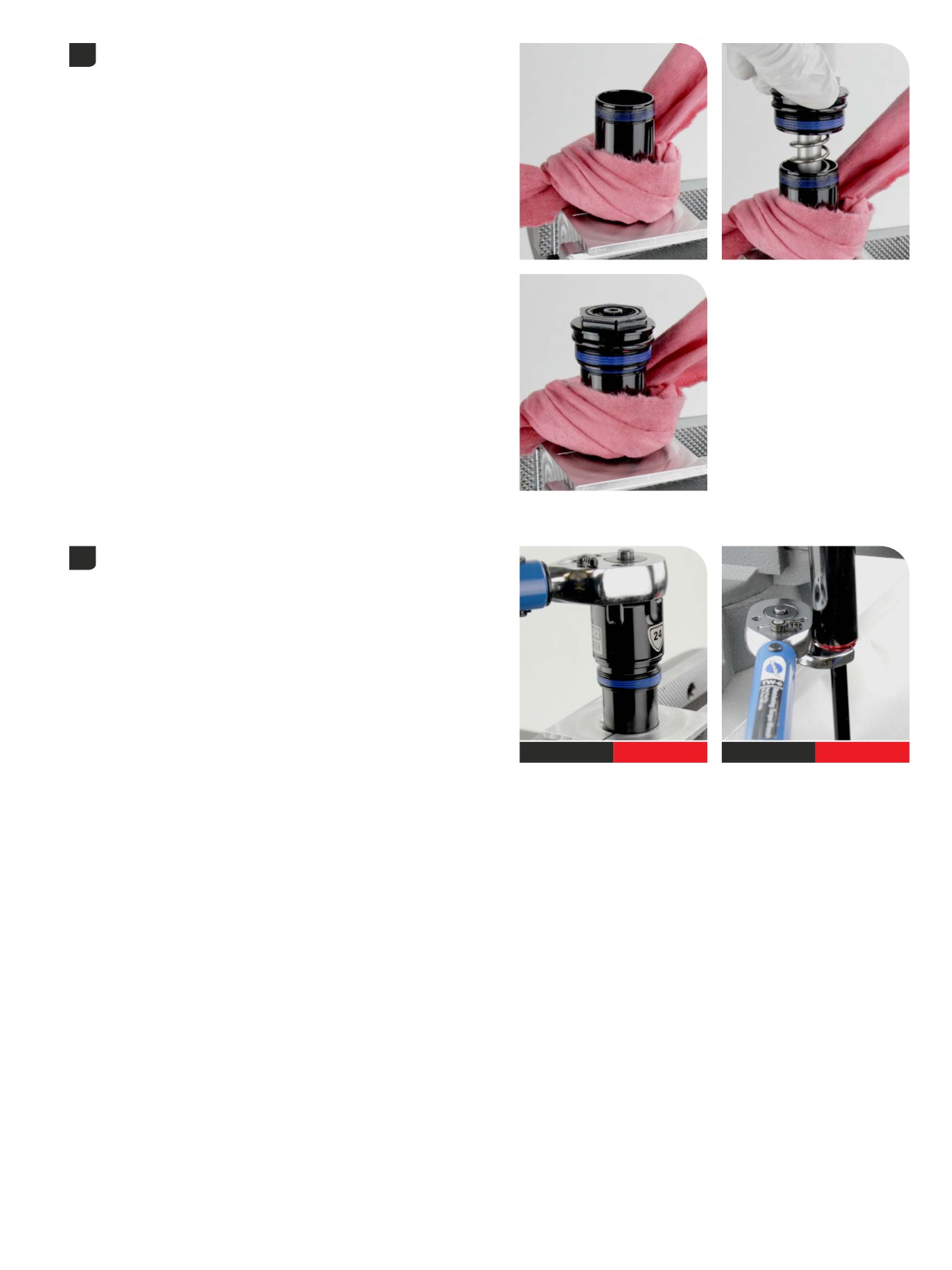
Secure a shop towel around the damper to absorb oil. Insert the
8
compression damper into the cartridge tube and slowly push it into
the tube. The rebound damper will slowly extend as the compression
damper is installed; this is normal.
Firmly push down and thread the top cap into the tube.
Tighten the top cap.
9
Tighten the rebound damper sealhead.
24 mm
9 N·m (80 in-lb)
19 mm
9 N·m (80 in-lb)
1
Damper Assembly - Rush RC
32
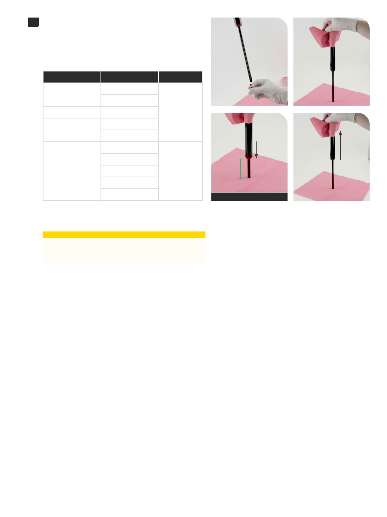
Remove the damper from the vise. Secure a shop towel loosely around
10
the damper cartridge over the bleed holes. Hold the damper vertical
and slowly pull the shaft out to full extension.
Remove the bottom bolt.
Slowly push the rebound damper shaft into the cartridge tube until
the rebound damper shaft is at the "B" measurement. Do not push the
rebound damper into the tube any further.
Fork
Fork travel (mm)
B (mm)
120
Pike
130
Pike / Lyrik
140
30
150
Lyrik
160
150
160
B
ZEB
170
54
180
190
See Table for Value
Extend the damper and push down to the "B" measurement 3-5 more
times. This will allow any excess oil and air to escape from the system.
Clean the damper.
⚠CAUTION
Oil may exit the cartridge tube bleed holes. Wear safety glasses
and keep your eyes and face away from the bleed holes when
compressing the rebound damper.
1
Damper Assembly - Rush RC
33
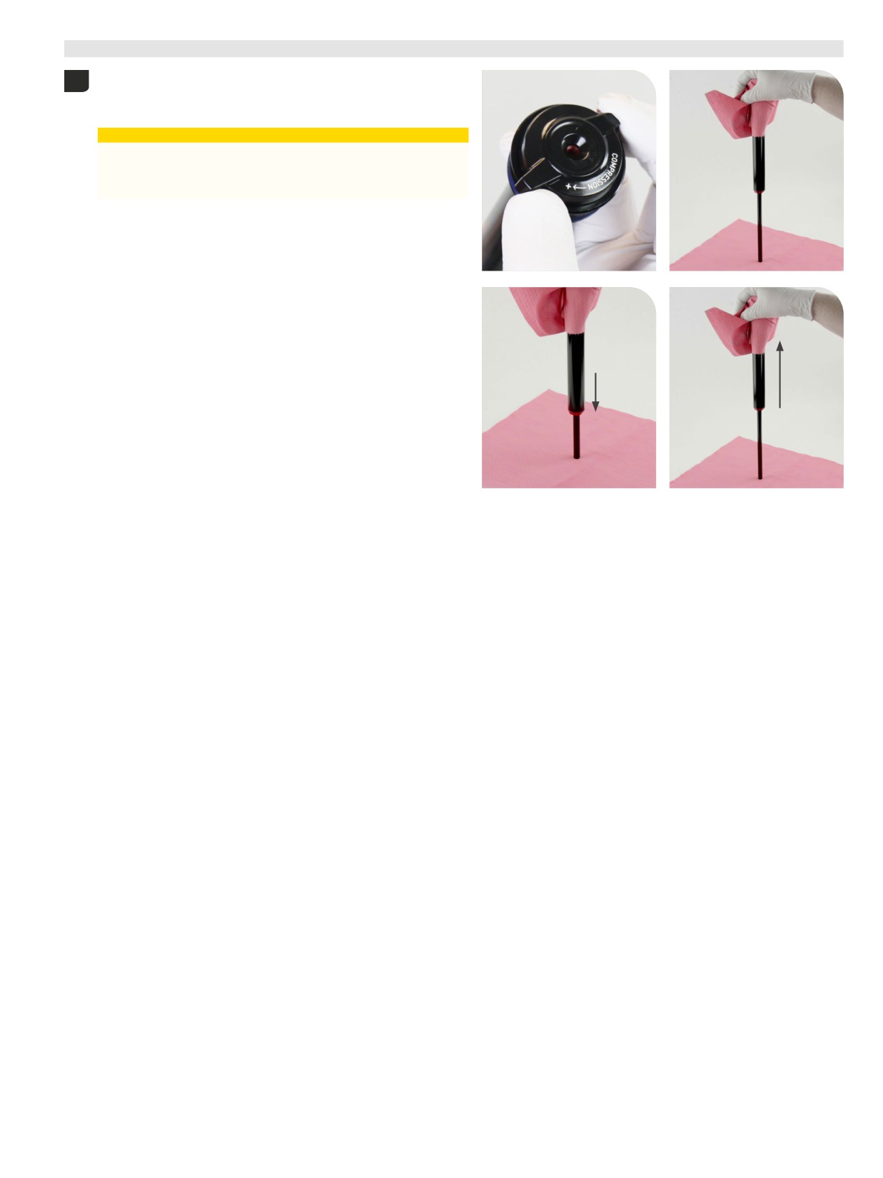
Test Compression
- Rush RC
Use the compression adjuster knob to rotate the adjuster cam to the
1
closed position, full clockwise until it stops.
Cover the bleed holes with a shop towel.
⚠CAUTION
Oil may exit the cartridge tube bleed holes. Wear safety glasses
and keep your eyes and face away from the bleed holes when
compressing the rebound damper.
Push down on the damper assembly slowly, about half way, to test the
firmest compression setting. Firm and consistent resistance should be
felt with no gaps in movement.
Rotate the compression damper to open setting and repeat the
compression test. Light consistent resistance should be felt with no
gaps in movement.
If gaps are felt during compression, repeat the oil fill and bleed
process. If the assembly process was successful, set the compression
damper to the open setting and remove the cable tie.
1
T
34
est Compression - Rush RC
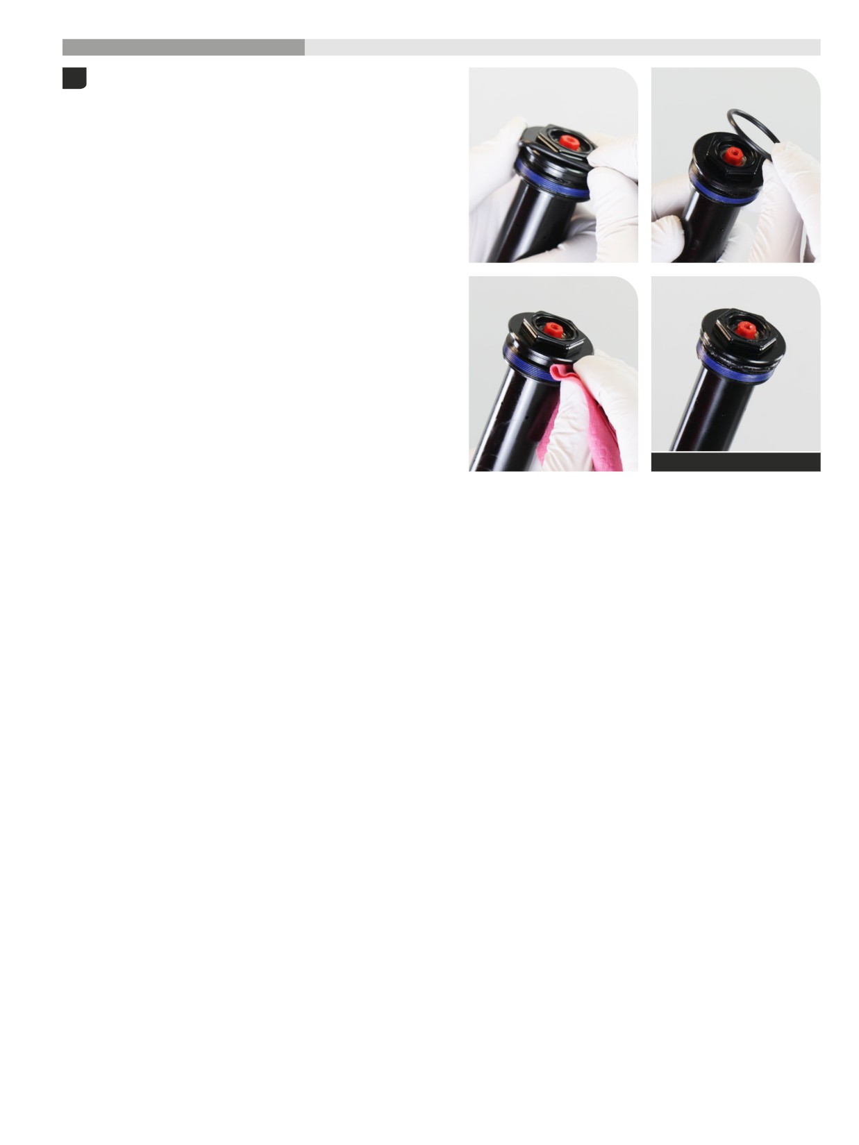
200 Hour Service
Damper Installation
- Rush RC
Remove the o-ring from the top cap.
1
Clean the top cap threads and o-ring groove.
Apply grease to a new o-ring and install it.
SRAM Butter Grease
1
Damper Installation - Rush RC
35
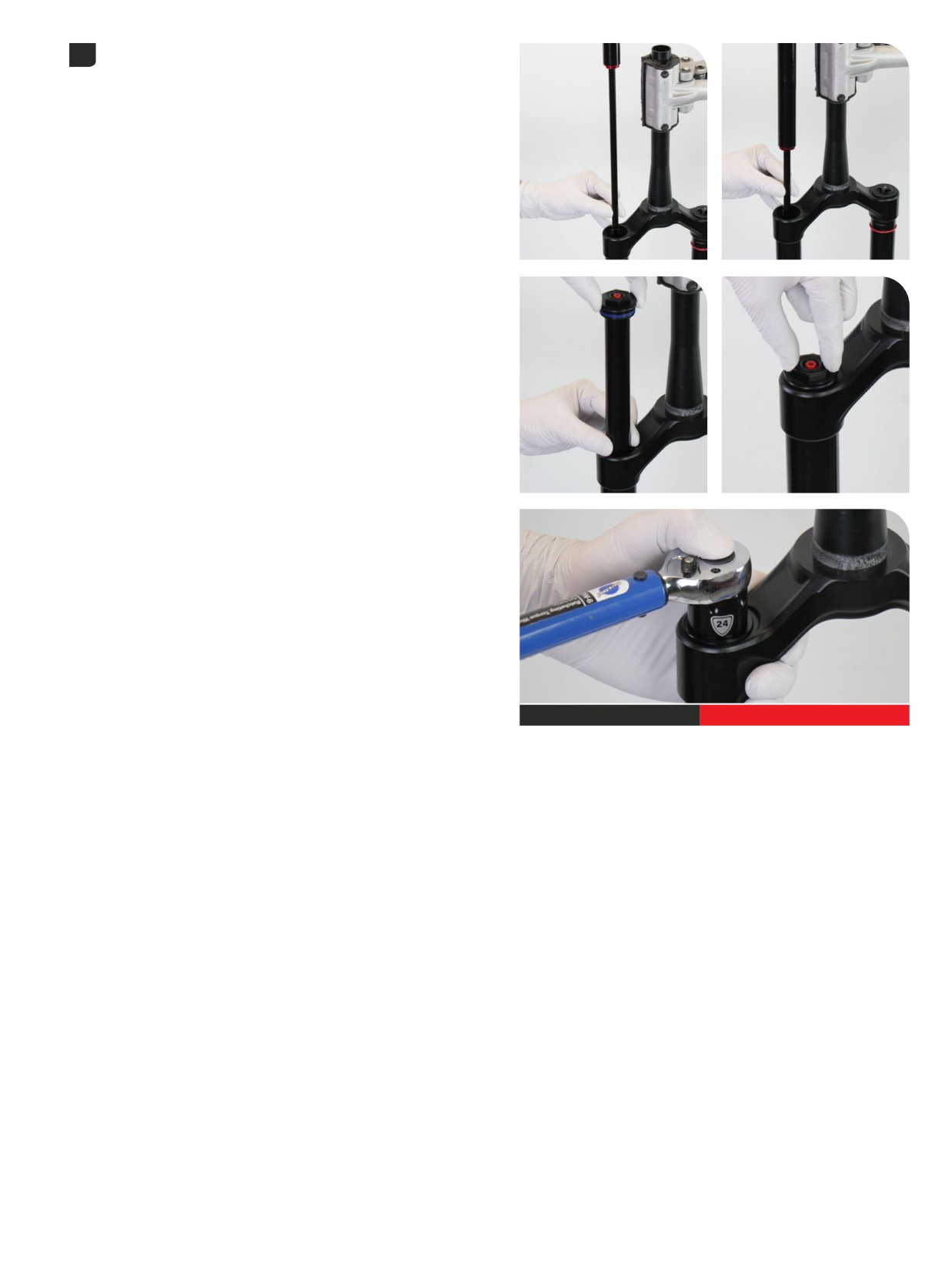
Install the damper assembly into the damper side upper tube. Use
2
your fingers to guide the damper and damper shaft into the upper tube
without scratching the shaft.
Thread the top cap into the upper tube and tighten it. Press down
firmly when tightening the top cap.
24 mm
28 N·m (250 in-lb)
Damper Installation - Rush RC
136
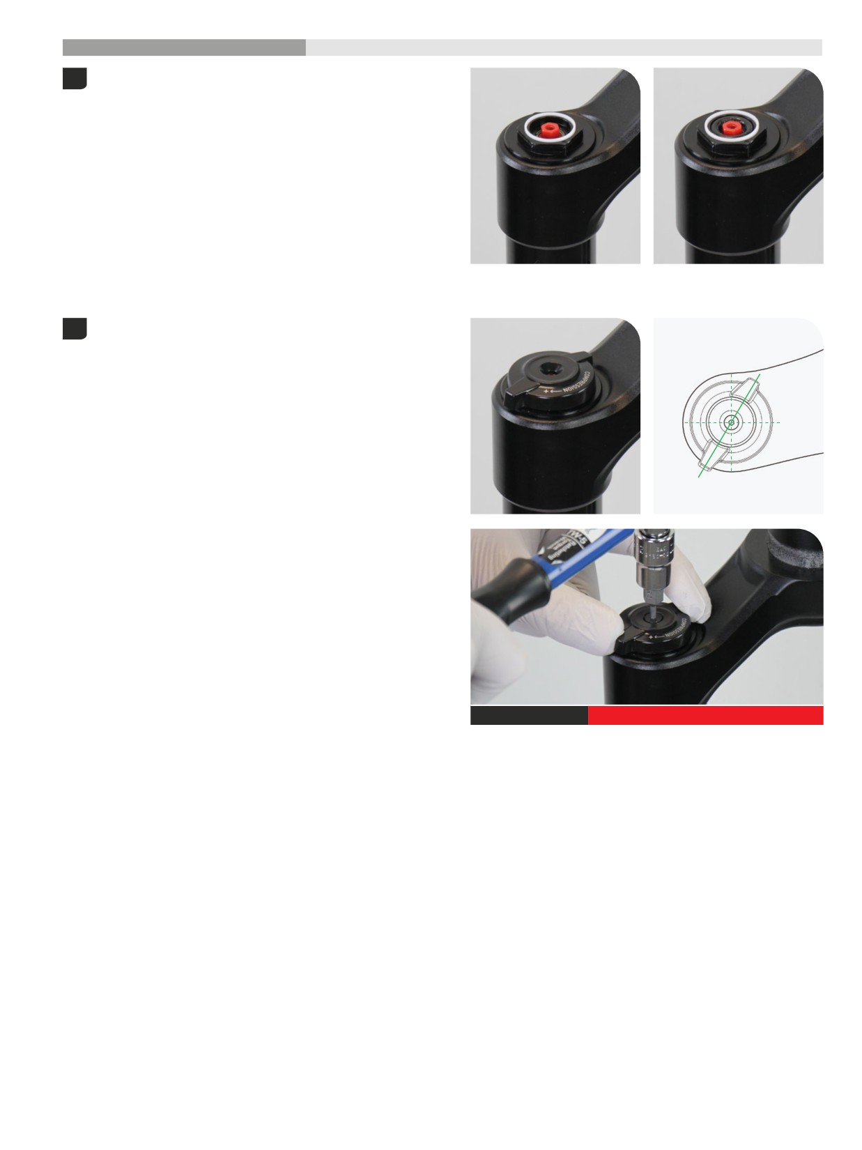
200 Hour Service
Controls Installation
- Rush RC
Apply grease and install a new o-ring and glide ring. Install the glide
1
ring into the groove and the o-ring in the center pocket of the top cap.
Install the adjuster knob with the tab in the 7-8 o'clock, unlocked
2
position.
Install and tighten the retaining screw.
Rear
Front
2.5 mm
0.75 - 1.10 N·m (6.6 - 9.7 in-lb)
Controls Installation - Rush RC
137
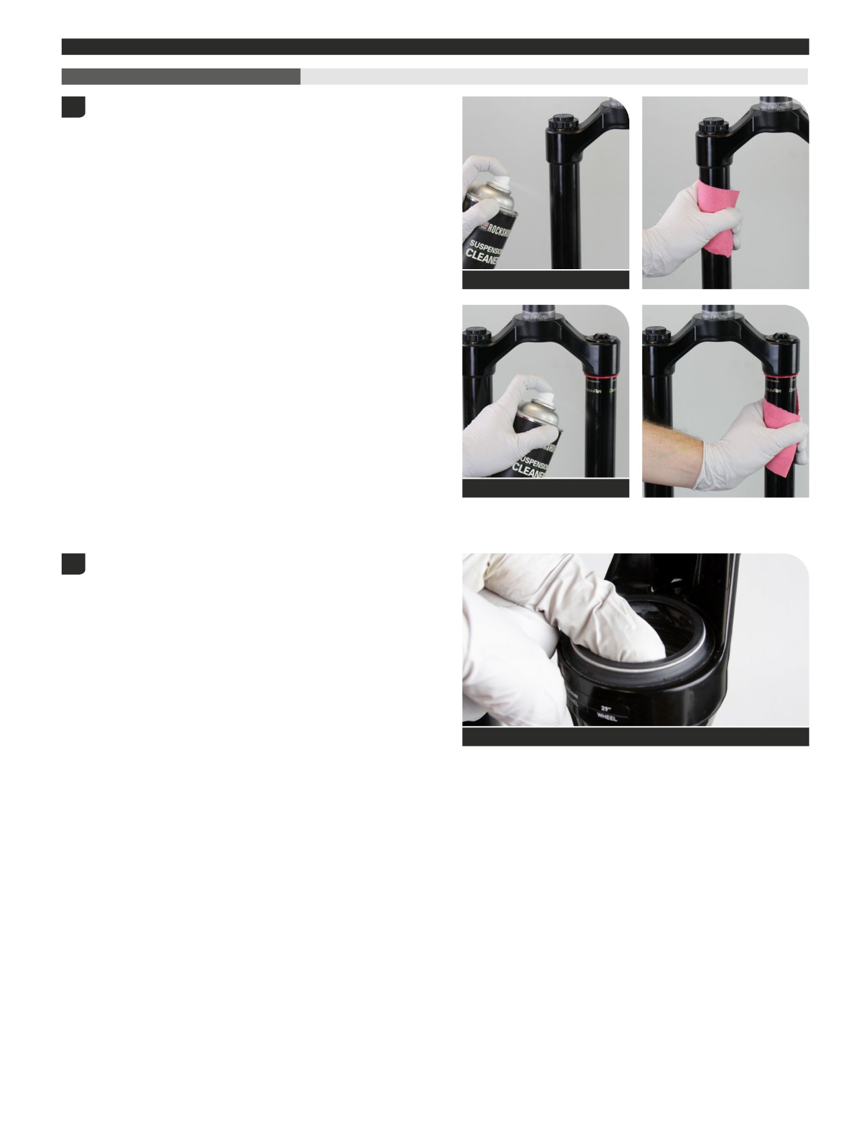
Lower Leg Assembly
50/200 Hour Service Lower Leg Installation
Clean the upper tubes.
1
RockShox Suspension Cleaner
RockShox Suspension Cleaner
Apply grease to the inner surfaces of the dust wiper seals.
2
SRAM Butter Grease
Lower Leg Assembly
138
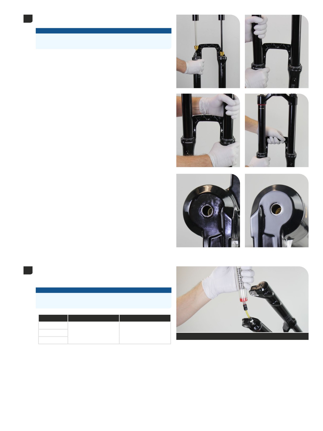
Install the lower leg assembly onto the upper tubes and slide it just
3
enough to engage the upper bushings with the upper tubes.
NOTICE
Make sure both wiper seals slide onto the tubes without folding the
outer lip of either seal.
The inside bottom of the lower leg should not contact the air spring
shaft and damper shaft, or ButterCups(s) (Ultimate). A gap between the
shafts, or ButterCups(s) (Ultimate), and the lower leg bolt holes should
be visible.
Position the fork at an angle with the bolt holes oriented upward.
4
Inject Maxima PLUSH Dynamic Suspension Lube Light into each lower
leg through the bottom bolt holes.
NOTICE
Do not exceed the recommended oil volume per leg as this can
damage the fork.
Fork
Damper Side (mL)
Spring Side (mL)
ZEB
Lyrik
30
15
Maxima PLUSH Dynamic Suspension Lube Light
See Table
Pike
Lower Leg Installation
139
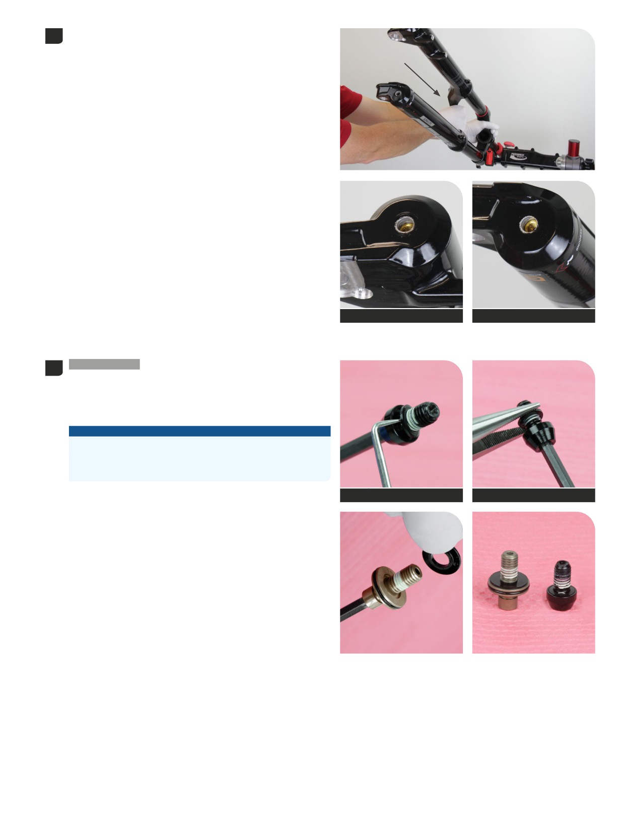
Slide the lower leg assembly toward the crown until it contacts the
5
shaft ends, and it stops.
The air spring and damper shaft, or ButterCups(s) (Ultimate) should be
visible through the bottom bolt holes.
Verify each shaft or ButterCups (Ultimate) is centered and seated in the
lower leg shaft/bolt hole, and no gap is visible between the lower leg
and each threaded shaft or ButterCups (Ultimate).
Align the shaft or ButterCups (Ultimate) into the bottom bolt holes if
needed.
Spring side
Damper side
200 Hour Service
Remove the old crush washers from each bottom
6
bolt.
Hold the crush washer with needle nose pliers and unthread it from the
bolt by turning the bolt counterclockwise. Discard the crush washers.
Clean the bolts and install new crush washers.
NOTICE
Do not damage the bolt threads.
Do not reuse crush washers or crush washer retainers. Dirty or
damaged crush washers can cause oil to leak from the fork.
5 mm
Pick
5 mm
Needle nose pliers
Lower Leg Installation
140
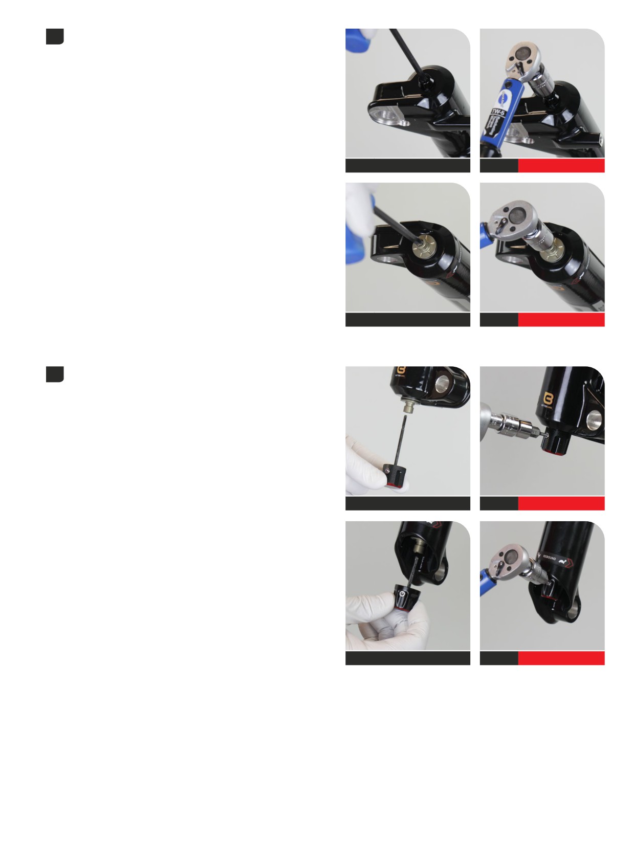
Install the solid bottom bolt into the spring side shaft.
7
Install the hollow bolt into the damper side shaft.
Tighten each bolt.
5 mm
Spring side
5 mm
6.8 N∙m (60 in-lb)
5 mm
Damper side
5 mm
6.8 N∙m (60 in-lb)
Apply a small amount of grease to the end of the rebound adjuster rod
8
to assist with installation.
Install the rebound adjuster knob onto the rebound damper bottom
bolt.
Press the knob firmly onto the bolt until it clicks into place.
Tighten the set screw.
Refer to your pre-service recorded rebound setting to adjust the
rebound damping.
SRAM Butter Grease
RC2
2.5 mm
0.84 N∙m (7.5 in-lb)
SRAM Butter Grease
RC
2.5 mm
0.84 N∙m (7.5 in-lb)
Lower Leg Installation
141
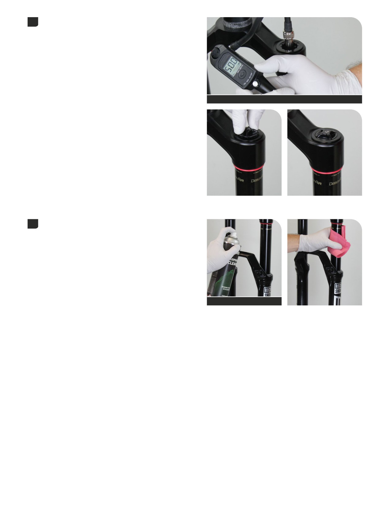
Refer to your pre-service recorded settings, or use the air chart on the
9
fork's lower leg, and pressurize the air spring.
You may see a drop in the indicated air pressure on the pump gauge
while filling the air spring; this is normal. Continue to fill the air spring to
the recommended air pressure.
Compressing the fork will equalize the positive and negative air
chambers. After the fork is cycled 3-4 times, check the pressure and
add air as needed.
Shock pump
Install the air valve cap.
Clean the entire fork.
10
RockShox Suspension Cleaner
This concludes the service of your RockShox suspension fork.
Lower Leg Installation
142

ASIAN HEADQUARTERS
WORLD HEADQUARTERS
EUROPEAN HEADQUARTERS
SRAM Taiwan
SRAM LLC
SRAM Europe
No. 1598-8 Chung Shan Road
1000 W. Fulton Market, 4th Floor
Paasbosweg 14-16
Shen Kang Hsiang, Taichung City
Chicago, Illinois 60607
3862ZS Nijkerk
Taiwan
U.S.A.
The Netherlands