Hovertrek Neoteric (hovercrafts). Manuals

Single Motor Hovercraft Manual
Please note:
This is a step by step procedure to build a sample single propeller
hovercraft.
Supporting images have been provided which include the design.
Readers are strongly urged to experiment with materials, dimensions
and components. The given model is not guaranteed to win
HoverOne, or give any sort of advantage.
All dimensions in centimeters, unless otherwise indicated.
About Single Motor Hovercraft:
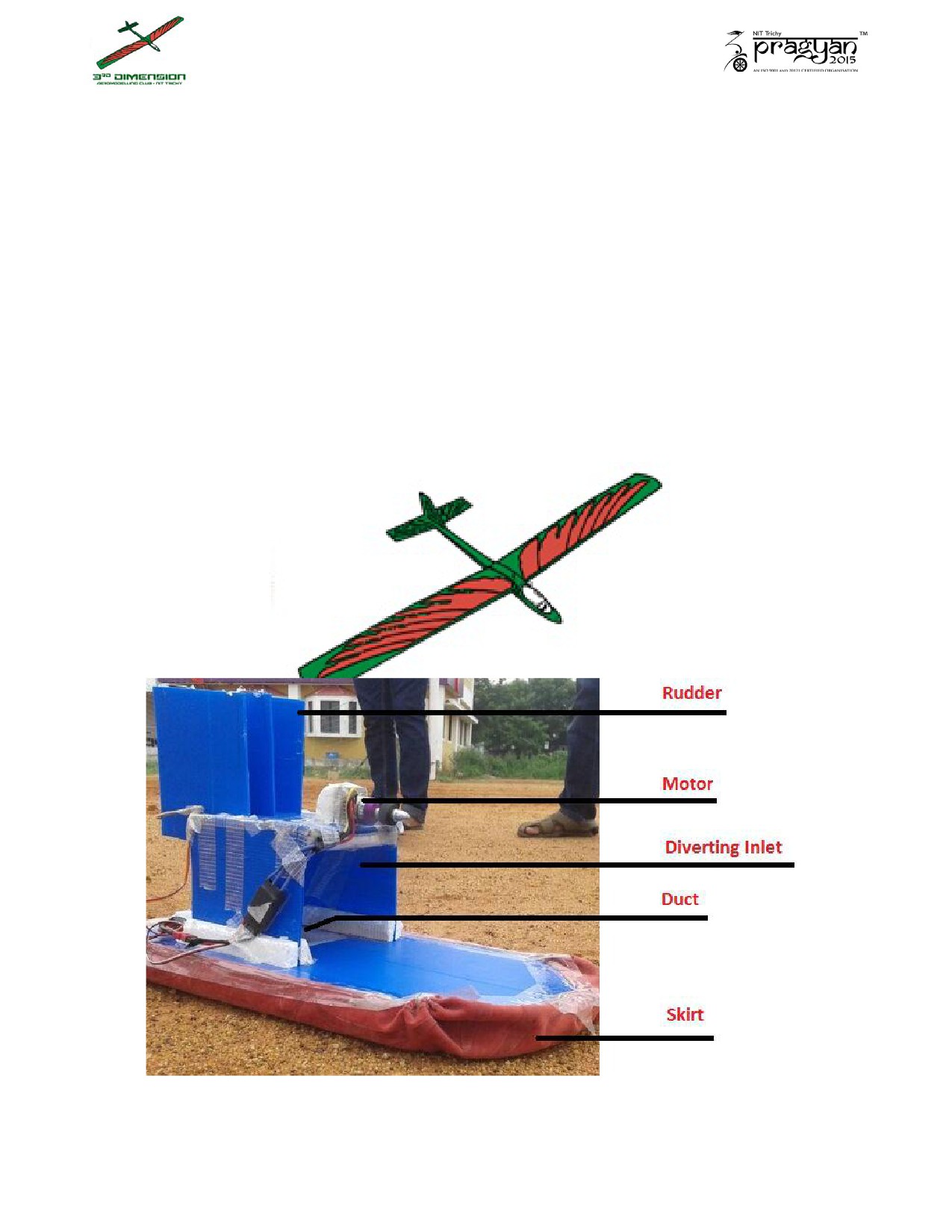
1. This Hovercraft uses only one fan to provide both lift and thrust.
2. The fan is usually mounted vertically using the top two thirds for
thrust and the bottom one third for lift (as shown in the figure below).
3. The lift air is directed into the skirt through the duct by the diverting
inlet.
4. The air under the hovercraft is known as the air cushion. This air
cushion leaks away under the bottom of the skirt to provide a film of
air which the hovercraft rides on.
5. The servo is used for positioning the rudder in the thrust air stream to
deflect the thrust air.
Advantages:
This hovercraft requires only one motor, electronic speed controller and
propeller for fabrication. Hence, it is cost effective.

Points to remember:
As a thumb rule for fixing dimensions, you can keep the length to be twice
the width of the hovercraft.
The capacity of the hovercraft\payload should be enough to support twice
the weight of the electronics on it.
Reducing the area won’t reduce weight, it increases the pressure.
Make your electronic connections water proof.
Check the direction of thrust before mounting the motor.
Give enough clearance for all dimensions.
The motor mount should not vibrate or be brittle.
Never apply hot glue or super glue to thermocol or coroplast.
General Instructions:
Fabrication Steps:
Instruction Set 1:
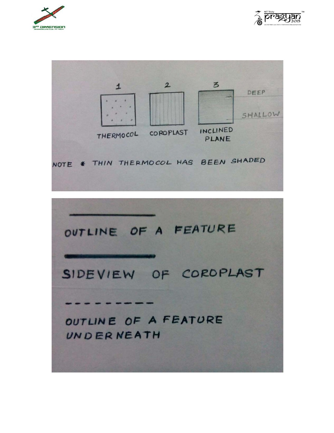
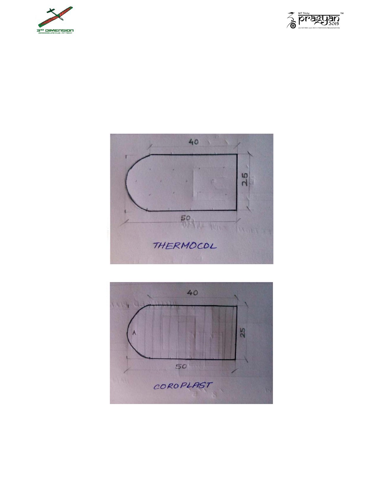
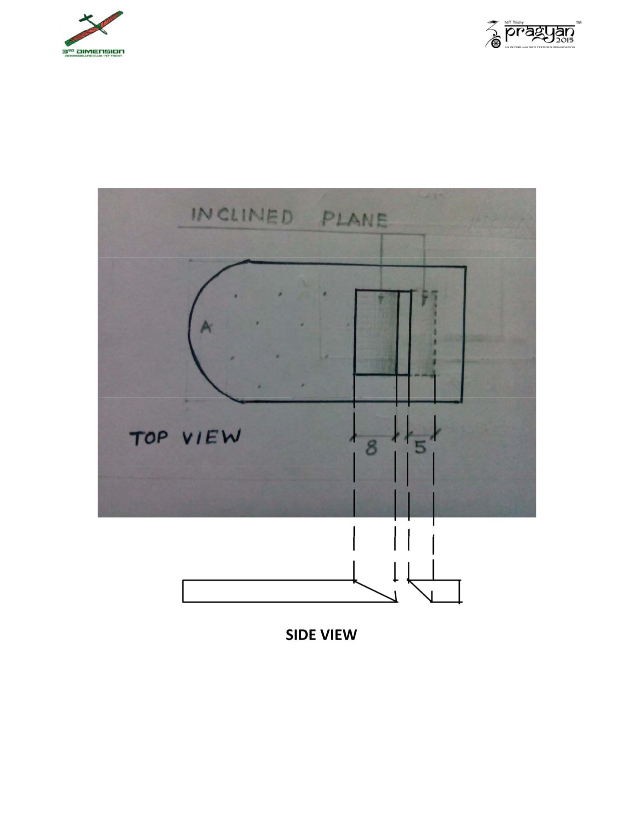
1. Cut pieces of thermocol and coroplast to rectangles of size 25cm by 50cm.
Then cut them as shown below, to make the base of the hovercraft. Please
note the flute orientation of the coroplast. (Indicated through lines in
figures)
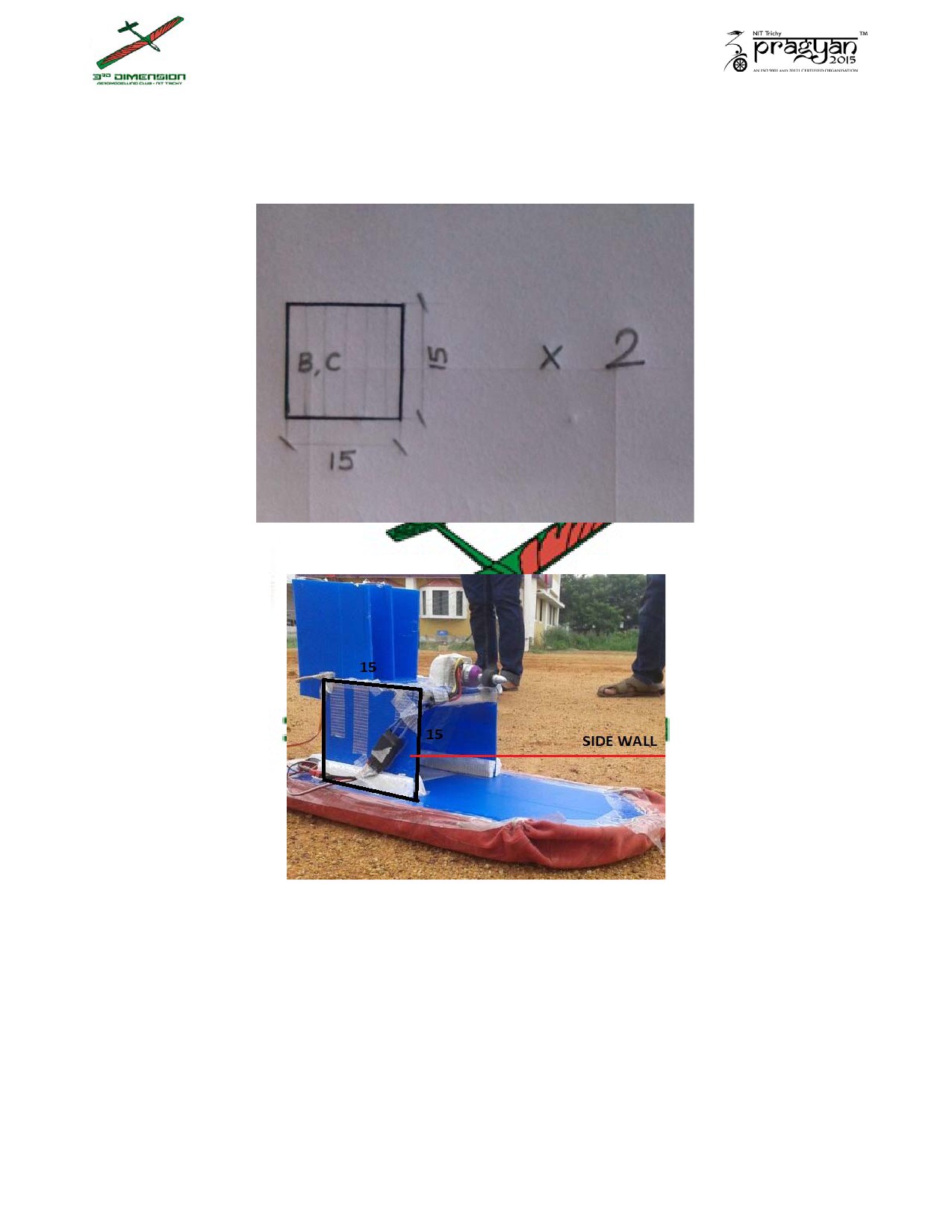
2. Cut 2 rectangles of dimensions 15 cm by 15 cm for the side walls
of the diverting inlet.
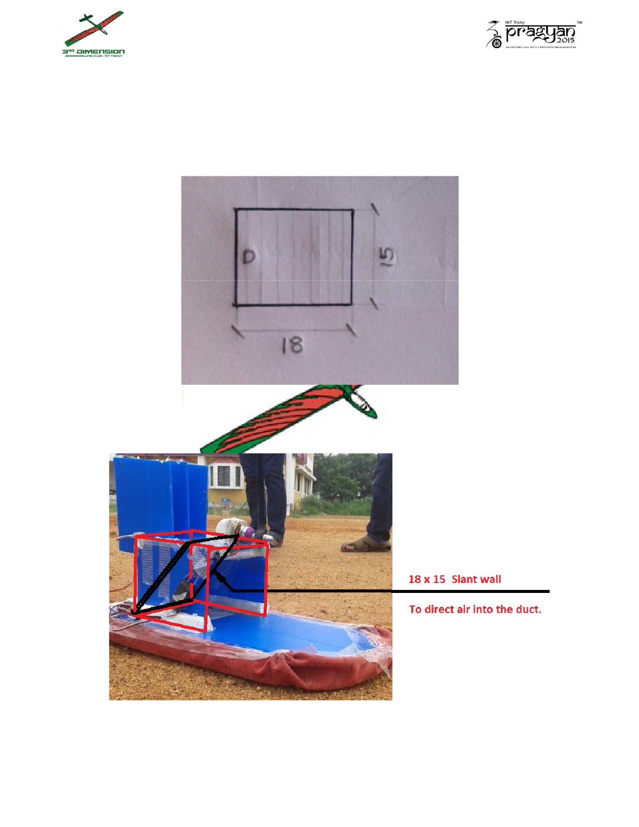
3. Cut a rectangle of dimensions 18 cm by 15 cm for the slant wall of
the duct from coroplast.
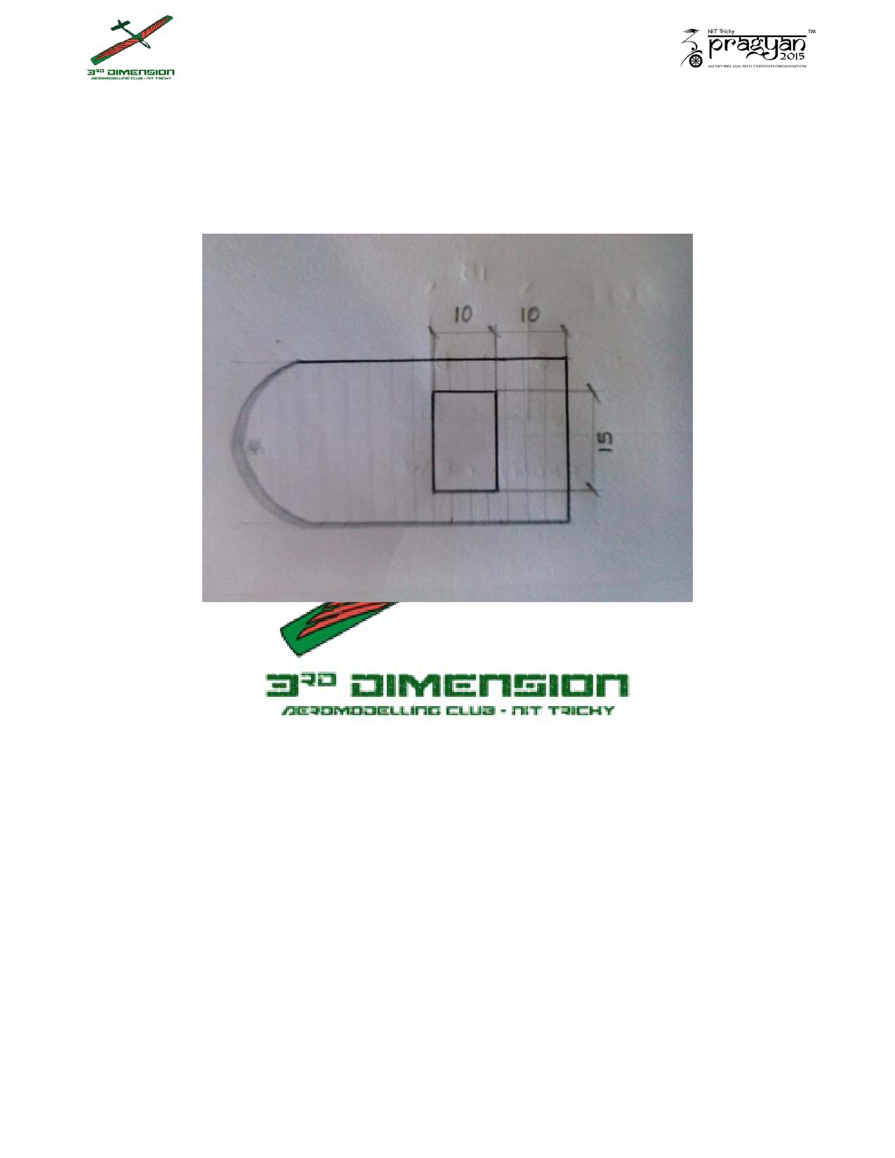
4. Draw a rectangle of dimensions 15 cm by 10 cm as shown on the 25 by
50 cm coroplast sheet and cut it out.
This cut is to provide the duct cavity.
Instruction Set 2:
1. Draw a rectangle of dimensions 15 cm by 10 cm on the thermocol as
shown and cut it out as illustrated in the figure given below.
Side view of the duct gives a clear idea.
2. Stick strips of thermocol to the base of the side wall pieces, and to the
edges along the length of the slant wall pieces.
(Refer to the image in Instruction set 1, point 2)
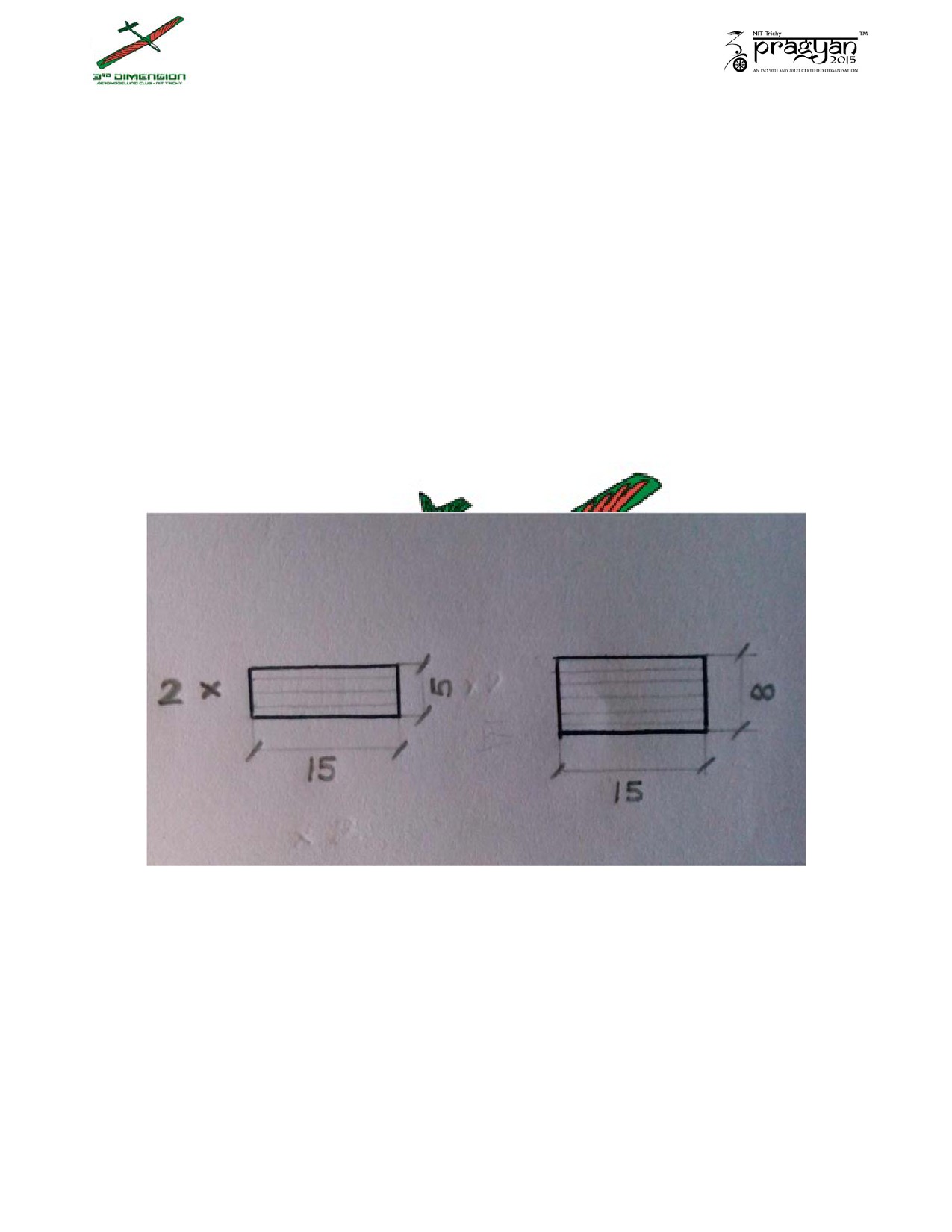
3. Cut out 3 pieces of coroplast, one of dimensions 8 cm by 15 cm and two of
dimensions 5 cm by 15 cm for the ceiling of the air box.

4. Cut out two rectangular pieces of dimension 16 cm by 13 cm for the
rudders. Make half cuts at 5 cm from one end on the breadth,
along the length in both pieces. (Refer to the diagrams to get a clear
picture)
Instructions Set 3:
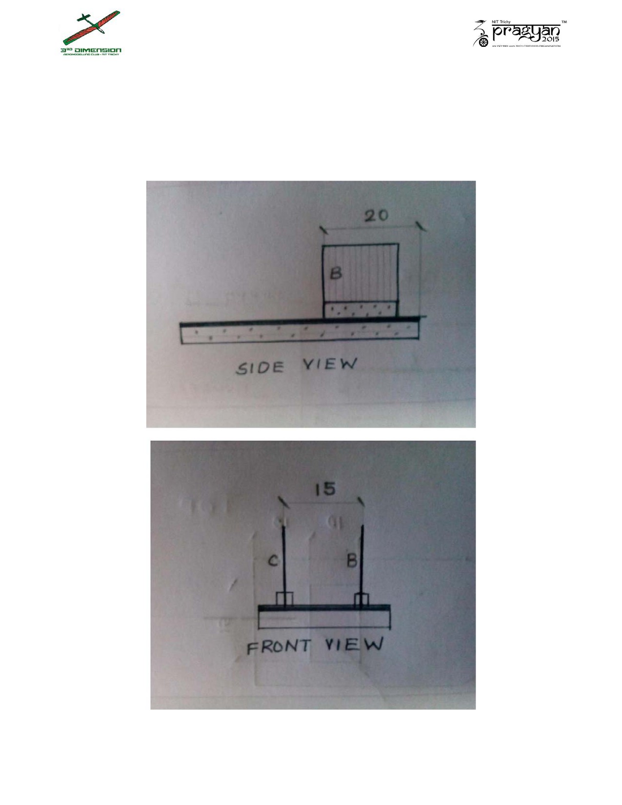
1. Stick the 25 by 50 coroplast on the thermocol, in such a way that the 15 by
10 rectangles are aligned.
2. Set up the side walls of the air box as shown below.
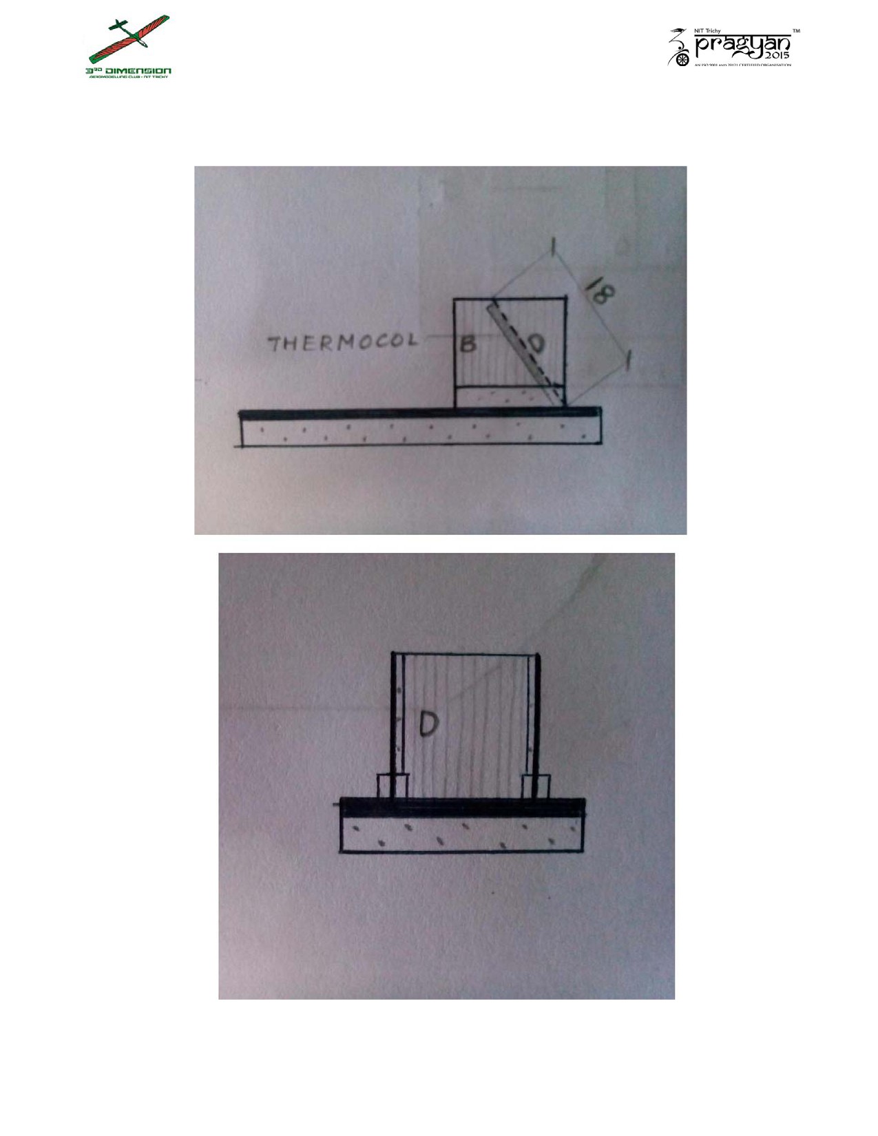
3. Set up the slant wall as shown. (Refer Instruction Set 1, Point 3)
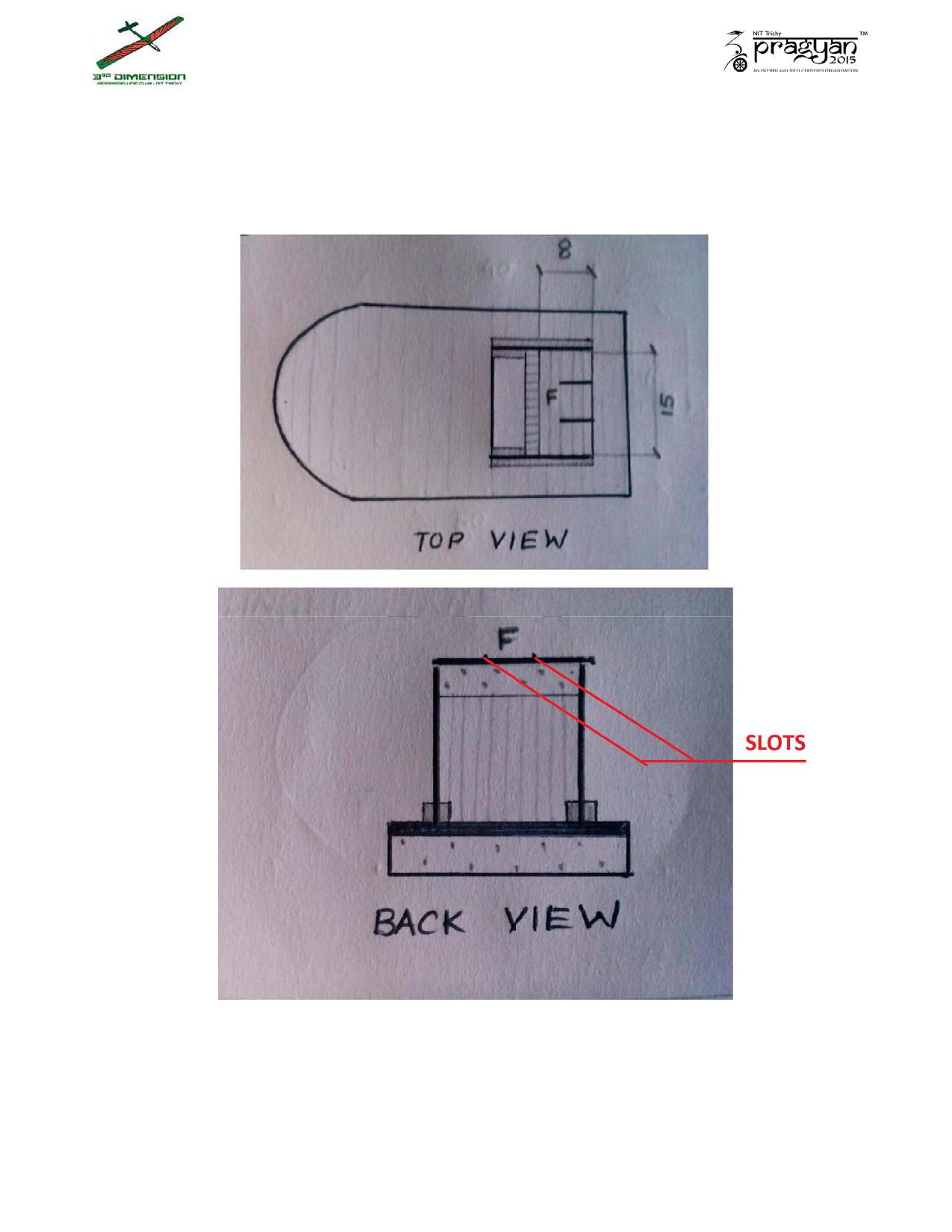
4. Make slots on the 8 by 15 piece as shown for attaching the rudders. Place
the coroplast as shown in the figure (thus forming the ceiling).
Instruction Set 4:
1. Insert the rudders into their slots and apply glue. Attach the servo firmly
to the back.(refer figure on next page)
2. Connect the rudders with connecting rods.
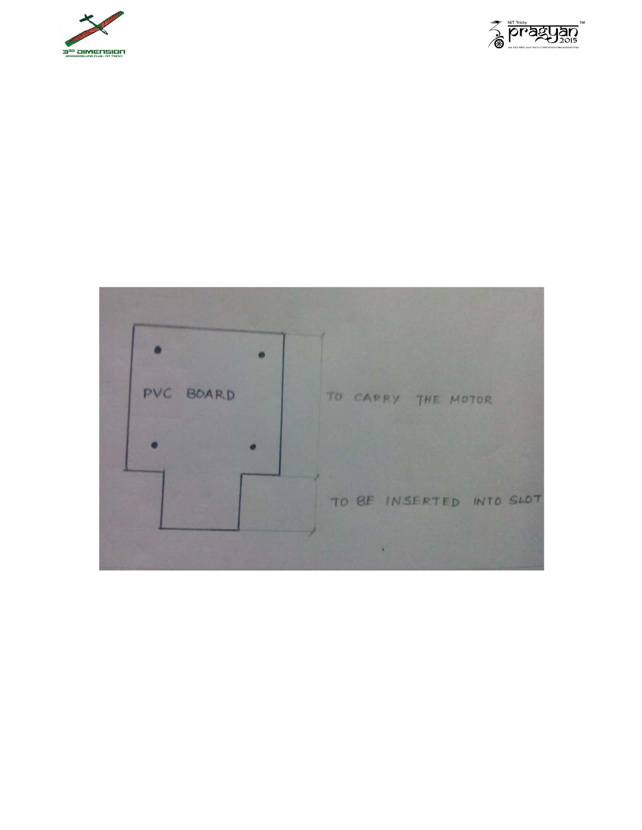
3. Prepare the motor mount using PVC board, with the given dimensions.
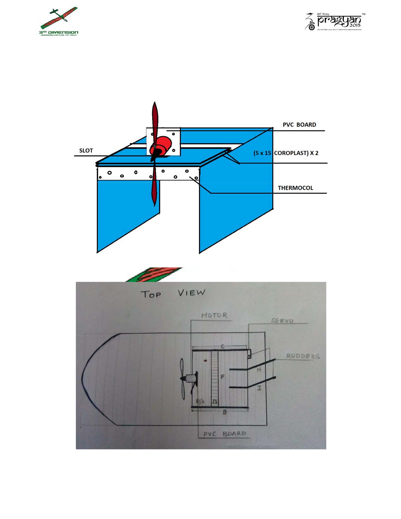
4. Stick the 5 by 15 pieces together (as indicated below) and make a slot to
allow the PVC motor mount to pass through.

Instruction Set 5:
1. Seal the side walls to the ceiling of the air box using connecting
rods and fiber tape.
2. Fit the propeller with the motor and screw the motor on to the
mount.
3. Fit the motor mount into the slot on the 5 by 15 piece of the air
box.
4. Connect the rudders with connecting rods, and connect one rudder to
the arm of the servo.
5. From the skirt material, cut out a rectangular piece of 30cm by 55cm. Fold
it and cut slits for the air to escape in a restricted manner.
Instruction Set 6:
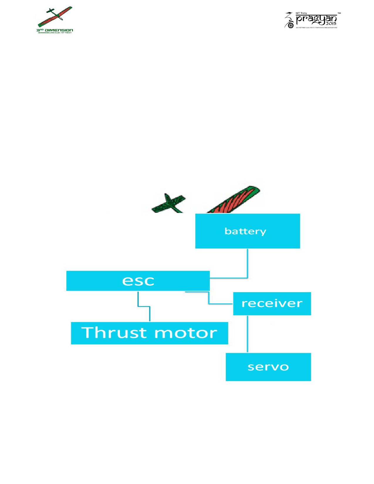
Electronics:
Make the connections between the various electronic components as shown in
the circuit diagram.

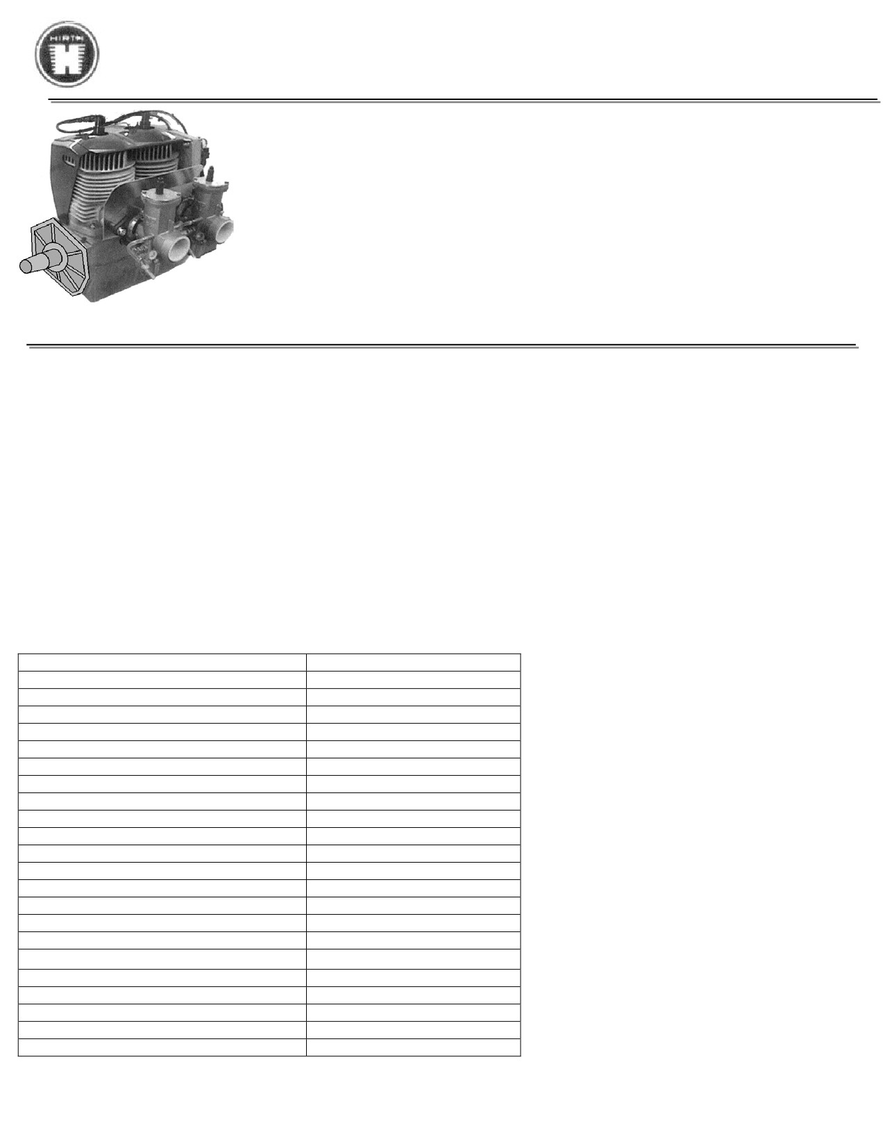
HIRTH 2703 Carburated - 55 hp
The 2703 V is an air cooled, piston controlled 2-cylinder-inline-2-stroke engine with one or two
carburetors and Nikasil coated cylinders. It has one of the highest power to weight ratio available
on the 50 HP engine market. Ideally suited for Ultralights, hovercraft, light experimental aircraft
and all applications where weight is an issue.
Factory recommended TBO is rated at 1000 hours at 75% power. The warranty of the crank shaft
is 3 years.
Technical Data
Specifications subject to change without prior notice
Type:
Two cylinder two stroke (Inline)
Displacement:
521 cm3 (31.79 cu in)
Stroke:
64mm (2.52 in)
Bore:
72mm (2.83 in)
Max. Performance:
38.2 kW (52 HP at 6500 rpm
According to DIN 70020
40.2 kW (55 HP at 6200 rpm
Specification with fan cooling
Max. Torque:
60 Nm (44.2 ft.lb) at 5700 rpm
67 Nm (49.4 ft.lb) at 5600 rpm
Carburation:
2 slide carburetor (Bing Size 54)
Ignition System:
CDI
Generator Power:
250W, 12V
Cooling:
Fan cooling
Weight:
31 kg (68.4lb)
Starting Device:
Recoil starter
Running direction:
Counter-clockwise, view to output shaft
Fuel mixture:
Mixture 1:50, 2-stroke-oil, fuel min. 95 octane (RON)
Form 16013
rev2

HIRTH ENGINE SETTING VALUES
55 HP Engine
Fan cooled engine
Engine
55HP Fan Cooled (FC)
Ign. Timing @ 2000 Carbureted
16° BTC
Spark Plug Heat VI *
280
Spark Plug Gap
0.020-0.024
No. of Carburetors
Two
Carburetor ID #
Bing 54 Carburetor (38mm)
Main Jet
160
Idle Jet
45
Idle Screw
1 Turn Out
Jet Needle
6P2 Position 1
Needle Jet
2.72
Needle Position
1
Do not exceed RPM
5800
Peak HP RPM
5500
HP (4i Peak RPM
55
Peak Torque RPM
5000
Peak Torque Ft. Lb.
53.2
Maximum CHT
535 ° F
Maximum EGT @ full power
1256 ° F
Maximum EGT @ cruise RPM
1330 ° F
Spark Plug *
Compression Pressure
120 PSI
* Optional Plugs : NGK BR 8 HS
: Champion RL86C or #830, L78C
: Nippon Denso W24 FSR-u
: Bosch W3AC
Useful Links:
Official Bing Manual: www.bingcarburetor.com/manual.html
Online Rebuild Manual: www.800-airwolf.com/pdffiles/ARTICLES/part%2052.PDF
Online Tuning Manual: www.ultralightnews.com/enginetroublshooting/techtips/techtips2.htm
Online Cleaning Guide: http://www.light-sport-aircraft.org/bing-54-carburetor-1.htm
Form 16941 rev2
Form 17119 rev2
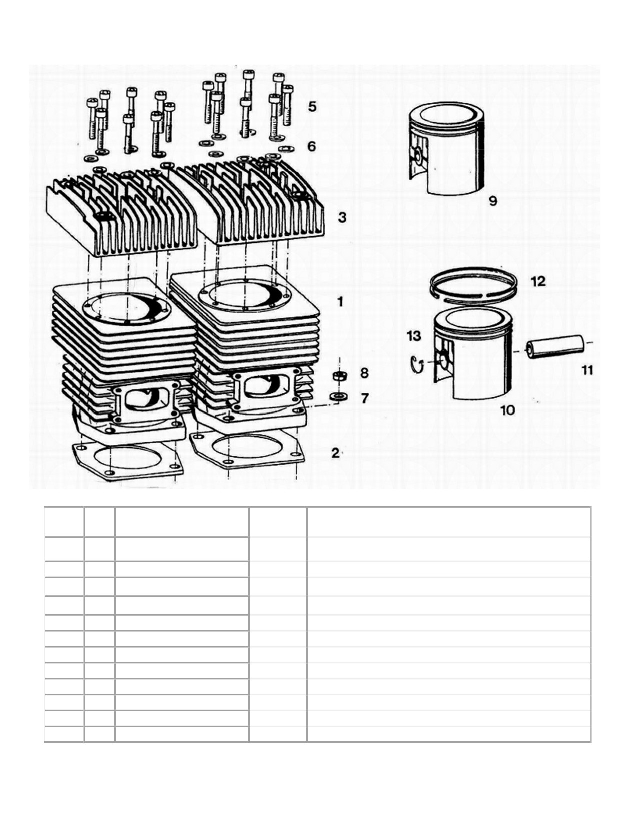
55HP Cylinders
(2703)
Fig.
Neoteric
Qty.
Description
Remark / Notes
No.
Part #
1
2
Cylinder
5860
2
2
Cylinder base gasket
3433
3
1
Cylinder head
6181
Single Ignition
5
16
Cylinder screw
6911
Torque = 11 Nm (8.1 ft-lb)
6
16
Washer
5994
7
8
Washer
6162
8
8
Hexagon head nut
6233
Torque = 23 - 26 Nm (17 - 19.2 ft-lb)
9
2
Piston set
5849
Includes Fig. 10, 11, 12, 13
10
2
Piston
7986
11
2
Piston pin
7987
12
4
Piston ring
6302
13
4
Retaining ring
6301
Form 17736 rev3
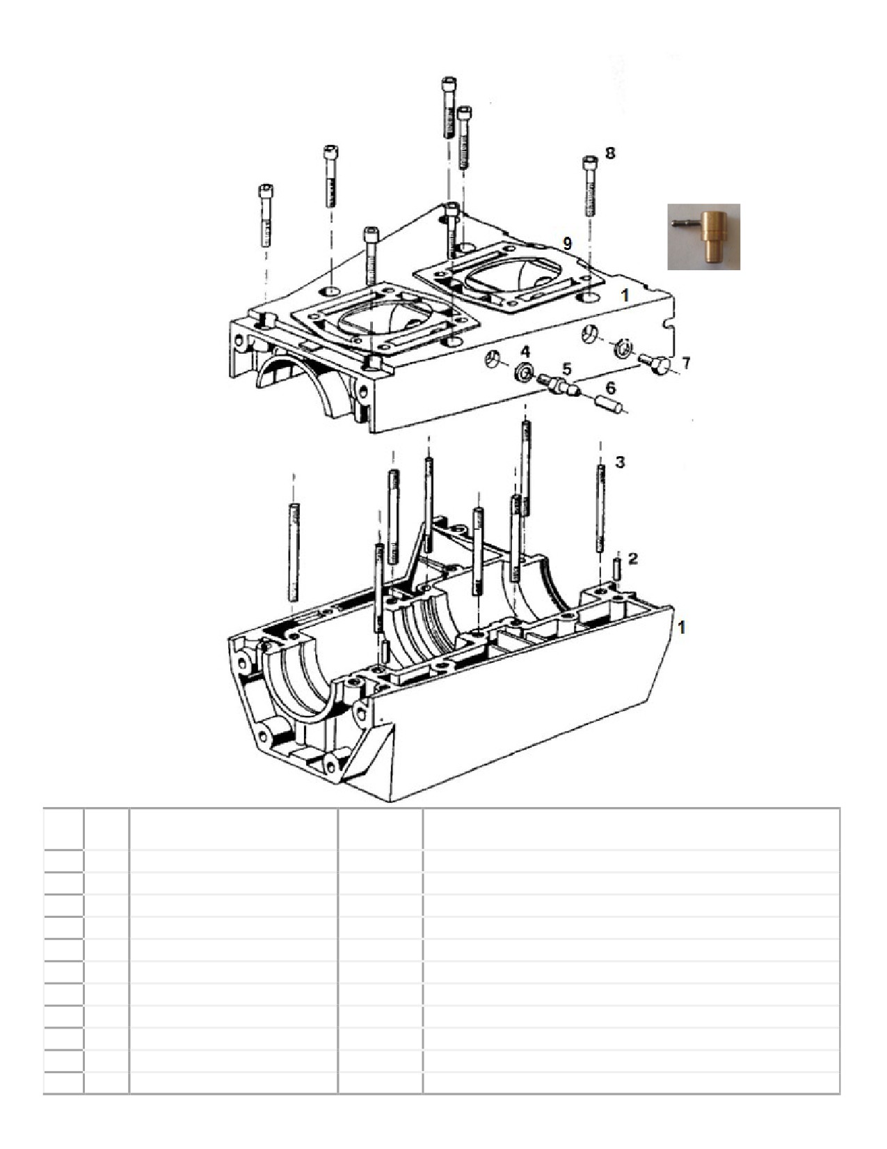
Spare part list - 55 HP Single Ignition
Crankcase 2703
10
Fig
Qty.
Description
Neoteric
Remark / Notes
No.
Part #
1
1
Crankcase, complete
7935
Incl. Pos. 2. 3
2
2
Alignment pin
7936
3
8
Stud screw
7163
Loctite 586
4
2
Sealing ring
5629
5
1
Hose nipple
5630
6
1
Rubber cap
7208
7
l
Hexagon head screw
6927
8
7
Cylinder screw
7937
Torque = 23 Nm (16.9 ft-lb) & Loctite 242
9
2
Cylinder Base Gasket
5455
See form 17749 for gasket set
10
1
Oil Injection Nipple
5490
Oil Inj. Engines With F.I.
Rubber Gasket Sealant
7842
Use as crankcase gasket
Form 17116 rev2
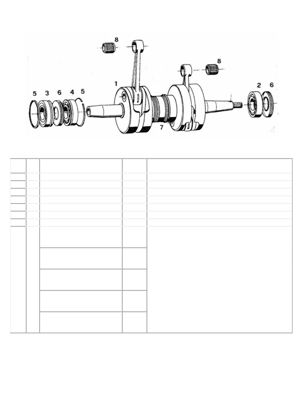
Crankshaft 2703
Fig.
Qty.
Description
Neoteric
Remark / Notes
No.
Part #
1
1
Crankshaft, complete
7911
Includes items 2 - 7
2
1
Deep groove ball bearing
5460
3
1
Deep groove ball bearing
5461
4
1
Deep groove ball bearing
5462
5
2
Circlip
7912
6
2
Shaft sealing ring
5453
7
1
Space ring
7913
Needle Bearing, Blue dot (#1)
7909
* Connecting Rods are Color-Coded with a Paint Dot on
the Piston end.
Needle Bearing, Yellow dot (#2)
6082
Engines built from 2010 onward also include a Number
Code next to the Paint Dot. The coding corresponds to the
8
2
correct Needle bearing size. (Approx 0.0003" [0.008mm]
graduation between each size)
Needle Bearing, Red dot (#3)
6083
Blue (#1) is the smallest and Green (#5) is the largest.
Connecting rods with a Red (#3) dot are most common.
Needle Bearing, White dot (#4)
5464
If the paint dot is missing and no number code can be
found, all bearings must be tried for the best fit.
Needle Bearing, Green dot (#5)
7910
Part 17118 rev2
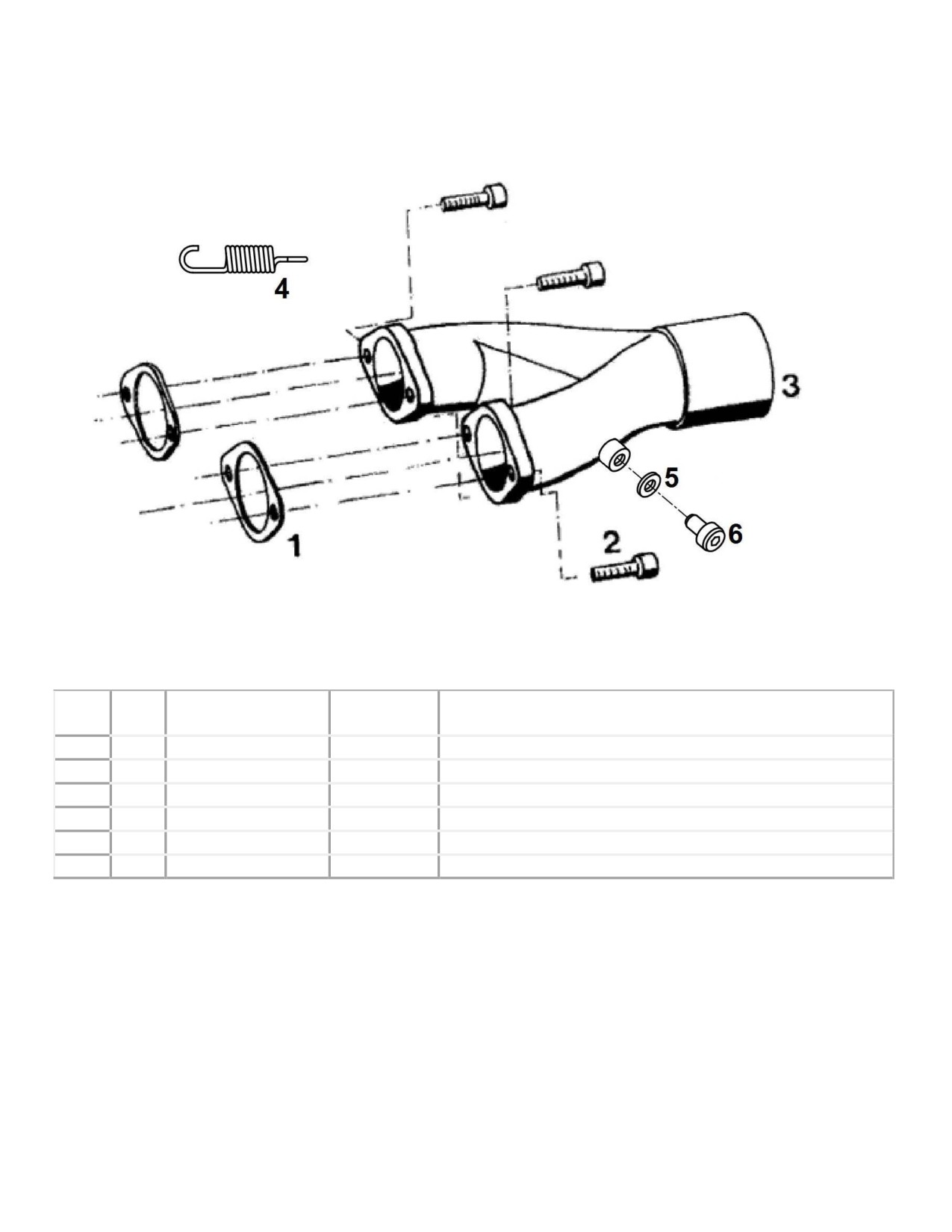
55HP Exhaust Header Pipe
(Y-Pipe)
Fig.
Neoteric
Qty.
Description
Remark / Notes
No.
Part #
1
2
Exhaust gasket
5245
2
4
Cylinder screw
6932
Torque = 23 - 26 Nm (16.9 - 19.2 ft-lb)
3
1
Exhaust manifold
5547
Prepared for temperature meas.
4
4
Exhaust Spring
5421
5
2
Copper Washer
7077
EGT Plugs; used when no EGT is installed
6
2
M8x1x10 SHCS
6934
EGT Plugs; used when no EGT is installed
Form 17120 rev2
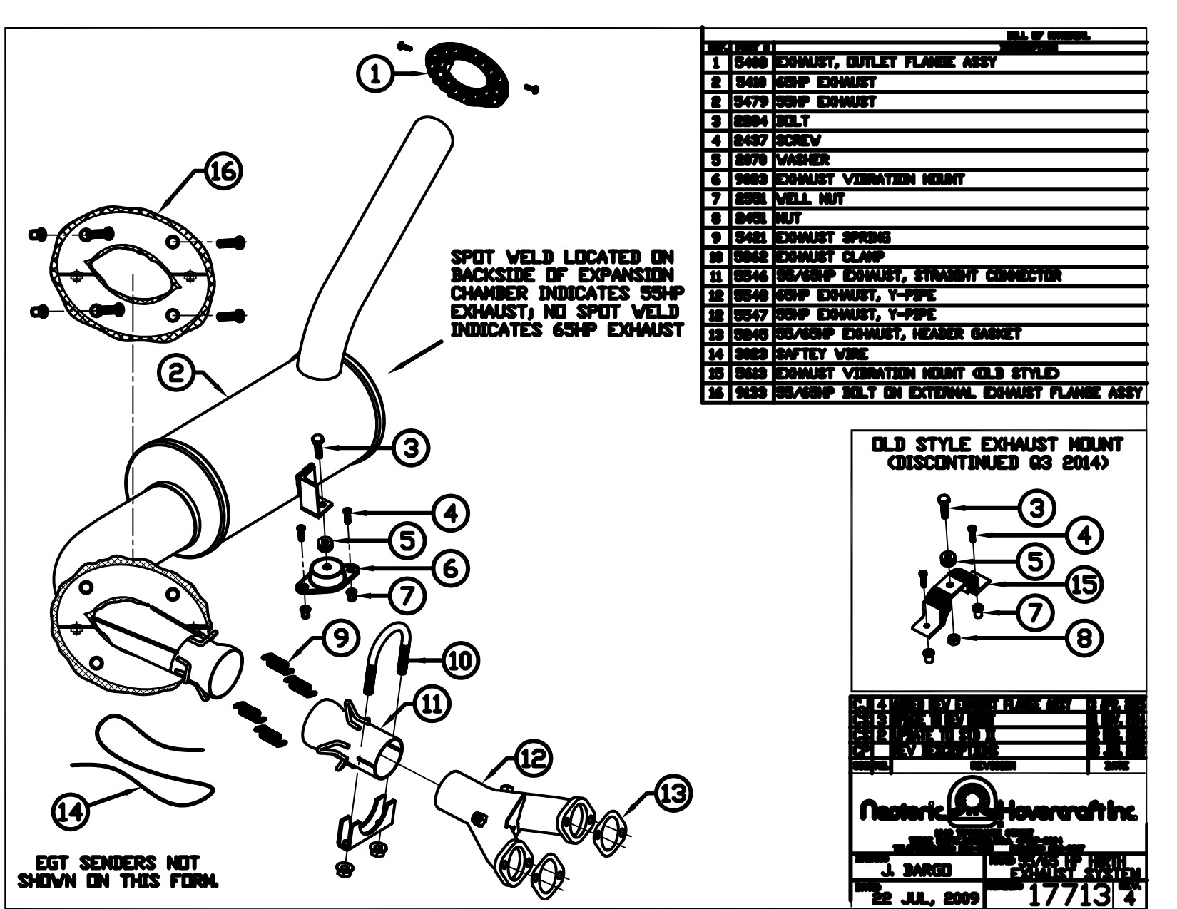
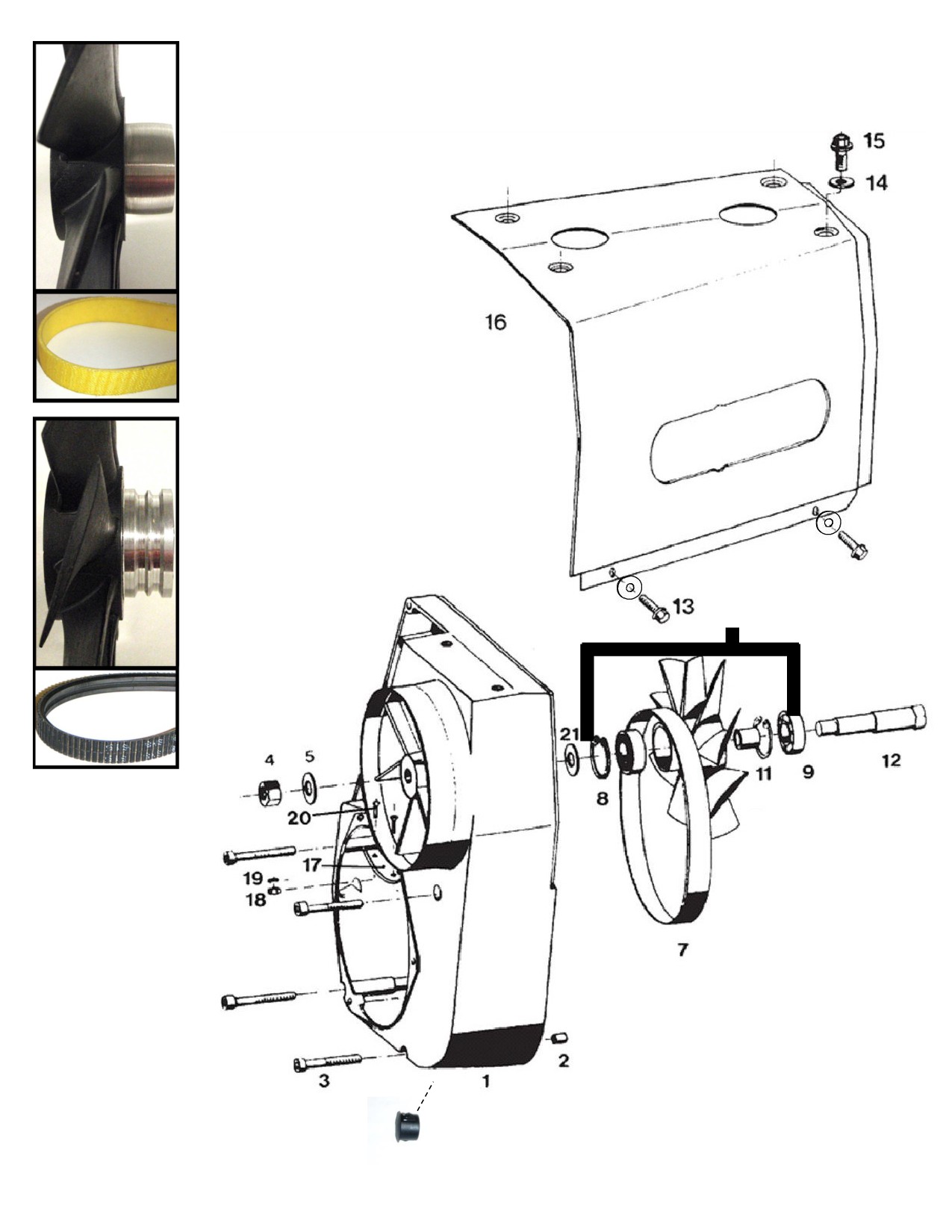
Fan cooling system 2703
* Flat Belt
Cooling Fan
(Old Style)
* Flat Belt
(Old Style)
Poly V Belt
Cooling Fan
(Current)
14
10
Poly V Flex
Belt
(Current)
NOTE:
If switching to poly
belt, must change
sprocket as well.
Sprocket item #6 on
form 17282 below
Sprocket Part#6389
22
Form 17121 rev3

55HP Cooling Fan System
(2703)
Fig.
Qty.
Description
Neoteric Part #
Remark / Notes
No.
Includes Fig No.
1
1
Fan housing, complete
7938
4, 5, 7, 8, 9, 10, 11, 12
2
3
Alignment sleeve
7939
3
4
Cylinder screw
3258
Torque = 9.6 - 11 Nm (7.1 - 8.1 ft-lb)
4
1
Hexagon head nut
6855
Torque = 27 - 30 Nm (19.9 - 22.1 ft-lb)
5
1
Washer
6856
*Used up to model year 2008
7*
1
Flat belt
3409
(Engine #901105 & Lower)
Currently used, from 2008 onward
7
1
Poly V Flex belt
6390
(Engine #901106 & Higher)
8
2
Locking ring
7940
9
2
Deep groove ball bearing
6887
Incl. Pos. 8, 9, 11
3408
10*
1
Fan wheel Assy, Flat belt
*Used up to model year 2008
(5879 - rebuilt)
(Engine #901105 & Lower)
Incl. Pos. 8, 9, 11
10
1
Fan wheel Assy, Poly V
6391
Currently used, from 2008 onward
(Engine #901106 & Higher)
Contains all parts required to convert engine
Poly V Cooling System
-
-
7457
from “Flat Belt” cooling system to
Conversion Kit
“Poly V Belt” cooling system.
11
1
Bushing
7941
12
1
Eccentric shaft
6857
13
2
Thread screw
5987
14
6
Washer
5996
15
4
Thread screw
5997
l6
1
Air guide cowl
5346
17
1
Metal plate
6183
18
2
Hexagon head nut
2694
19
2
Washer
7942
20
2
Screw
2693
21
1
Washer
7943
22
1
Hole Plug
2449
Covers Hole In Housing
Form 17363 rev2
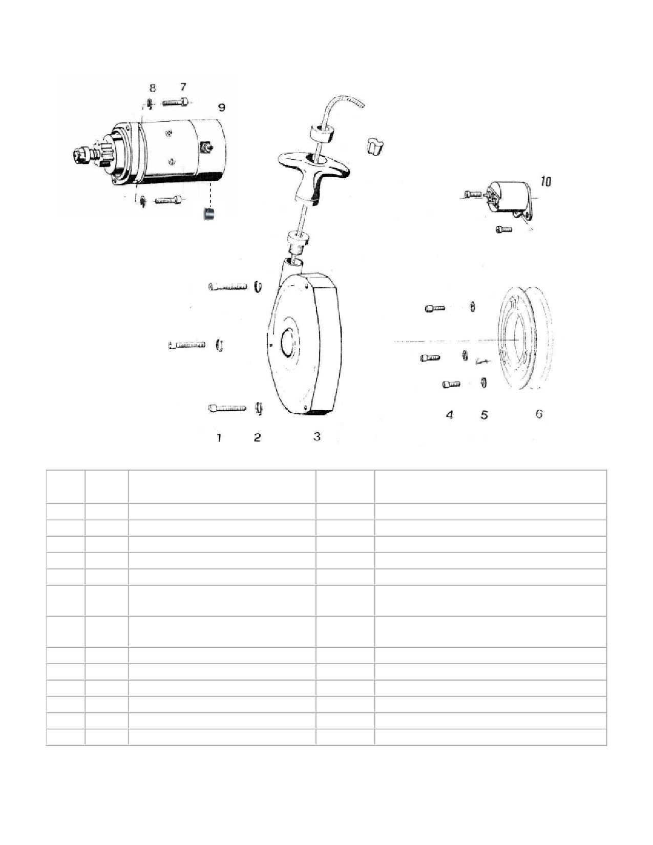
55HP Starting Device
(2703)
11
Fig.
Qty
Description
Neoteric
Remark / Notes
No.
Part #
1
3
Cylinder screw
6911
Torque = 9.6 - 11 Nm (7.1 - 8.1 ft-lb)
2
3
Spring ring
6940
3
1
Starter, mounted
5267
4
3
Cylinder screw
7944
Torque = 23 - 28 Nm (17 - 20.7 ft-lb)
5
3
Tab washer
5995
6*
1
Driving dog with starter, Flat
6203
*Used up to model year 2008
(Engine #901105 & Lower)
6
1
Driving dog with starter, Poly-V
6389
Currently used, from 2008 onward
(Engine #901106 & Higher)
7
2
Cylinder screw
2348
Torque = 23 - 28 Nm (17 - 20.7 ft-lb)
8
2
Tab washer
5995
9
1
Electric Starter, Hirth
6982
Old starter 5545
-
1
Electric Starter, Alternative
7563
Replacement for Customers
10
1
Starter Solenoid
5417
11
1
Hole Plug
9172
Plugs Drain Hole In Starter
Form 17684 rev2
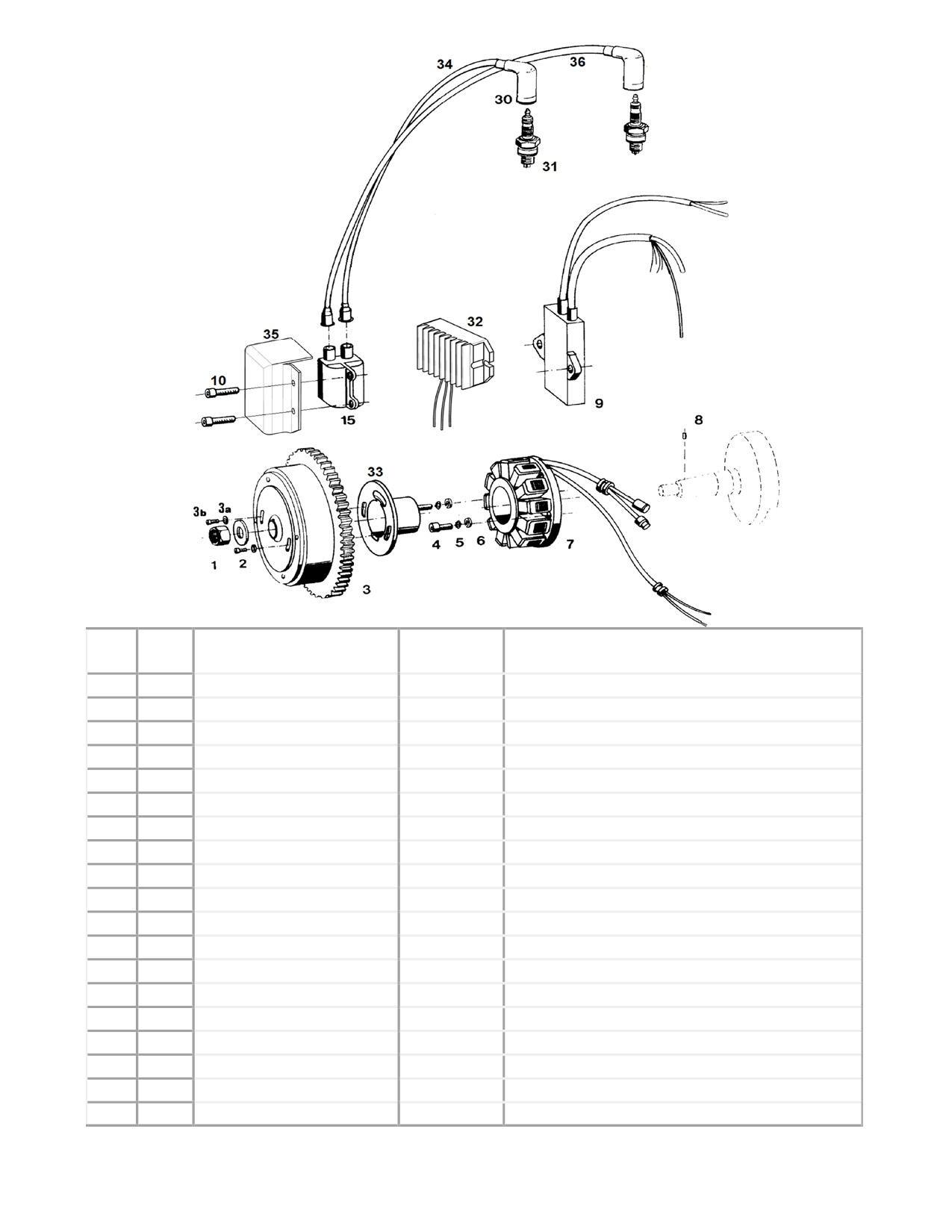
55/65HP Ignition System
Fig.
Qty.
Description
Neoteric
Remark/Notes
No.
Part #
1
1
Hexagon head nut
6939
Torque = 140 - 150 Nm (103.3 - 110.6 ft-lb)
2
1
Washer
7196
3
1
Flywheel with gear ring
7984
Includes fig. 3a, 3b, 33
4
2
Cylinder screw
7182
Neoteric does not stock
5
2
Washer
5994
6
2
Washer
6936
Torque = 4 - 4.5 Nm (3 - 3.3 ft-lb)
7
1
Stator plate complete
5591
8
1
Flywheel alignment pin
7985
9
1
CDI - Box
5664
Mounted with silicone
10
2
Coil Mounting Screw
2469
15
1
Ignition coil
5682
Includes fig. 15
30
2
Spark plug cap
5826
31
2
Spark plug
5668
Do not mix spark plug types
32
1
Voltage Regulator
9876
33
1
Magnet Support
5724
34
1
Spark plug lead, short
5666
Wire only; does not include fig. 30
35
1
Coil spray guard
6683
36
1
Spark plug lead, long
5665
Wire only; does not include fig. 30
-
-
Spark Plug lead set
5661
Includes fig. 30, 34, 36
Form 17683 rev2
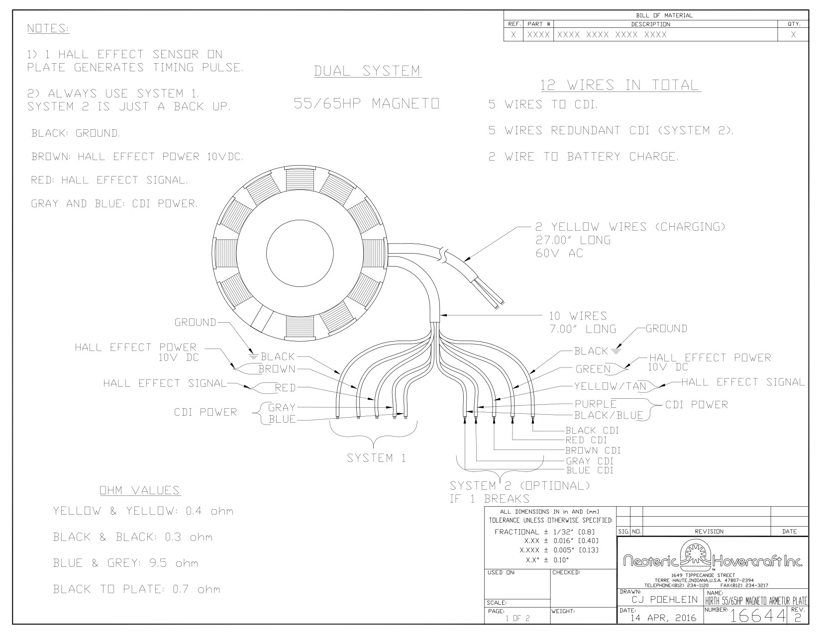
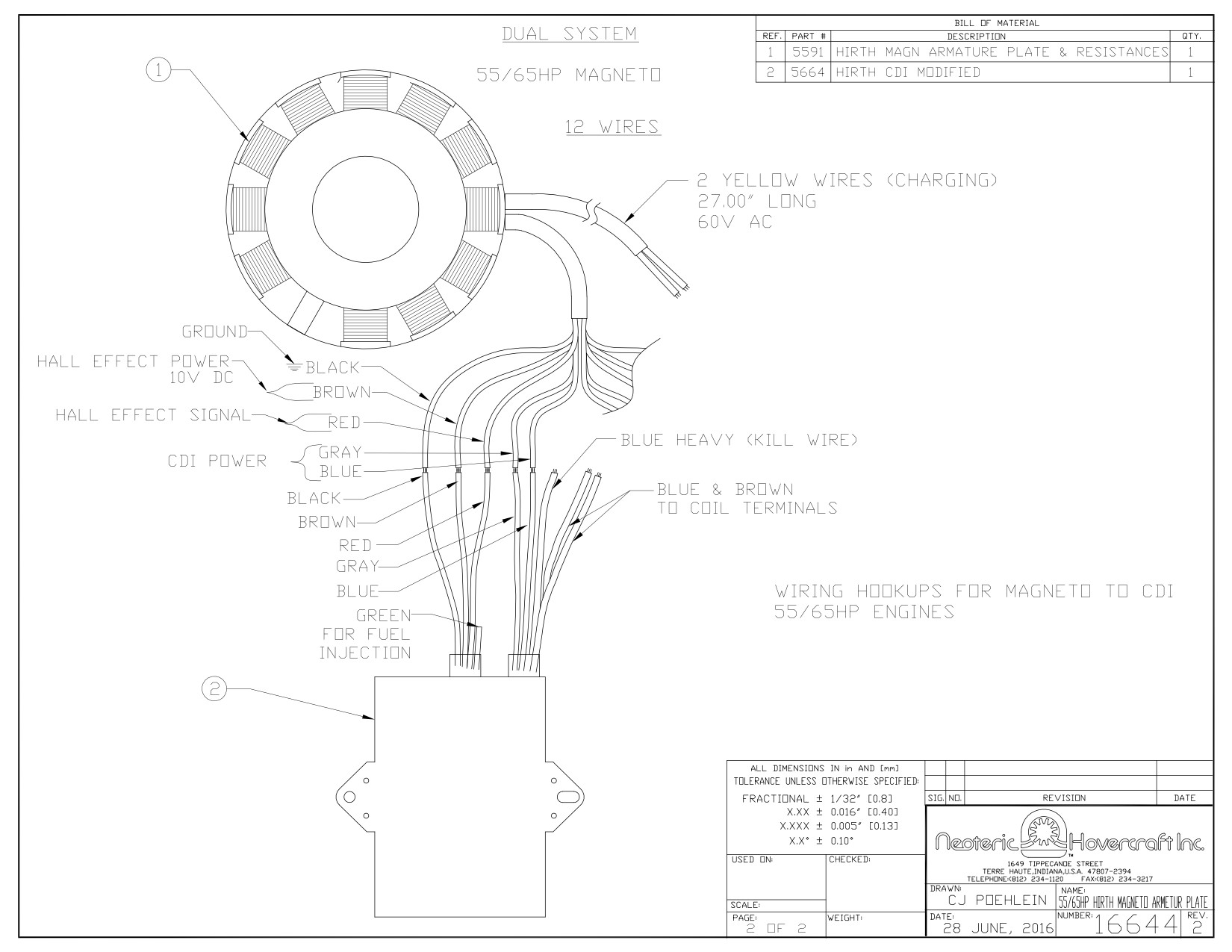
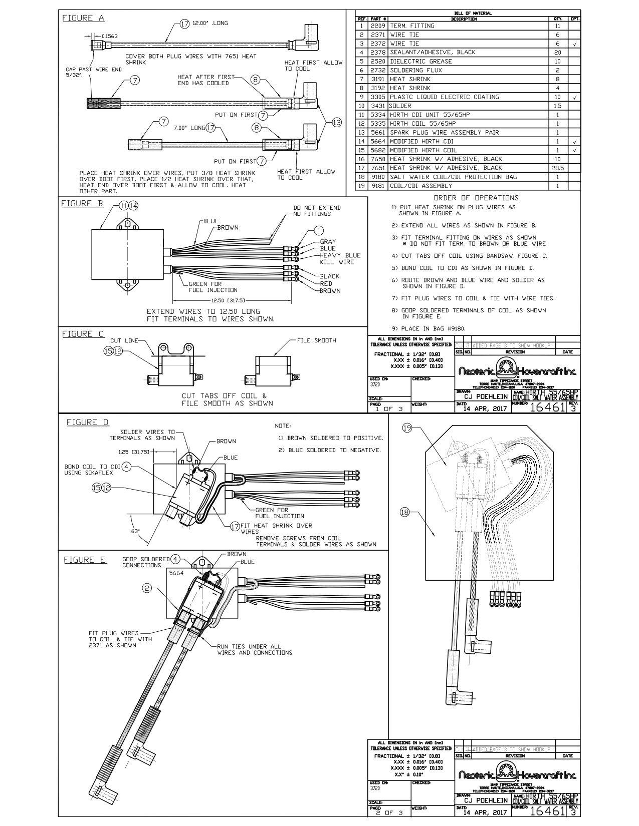
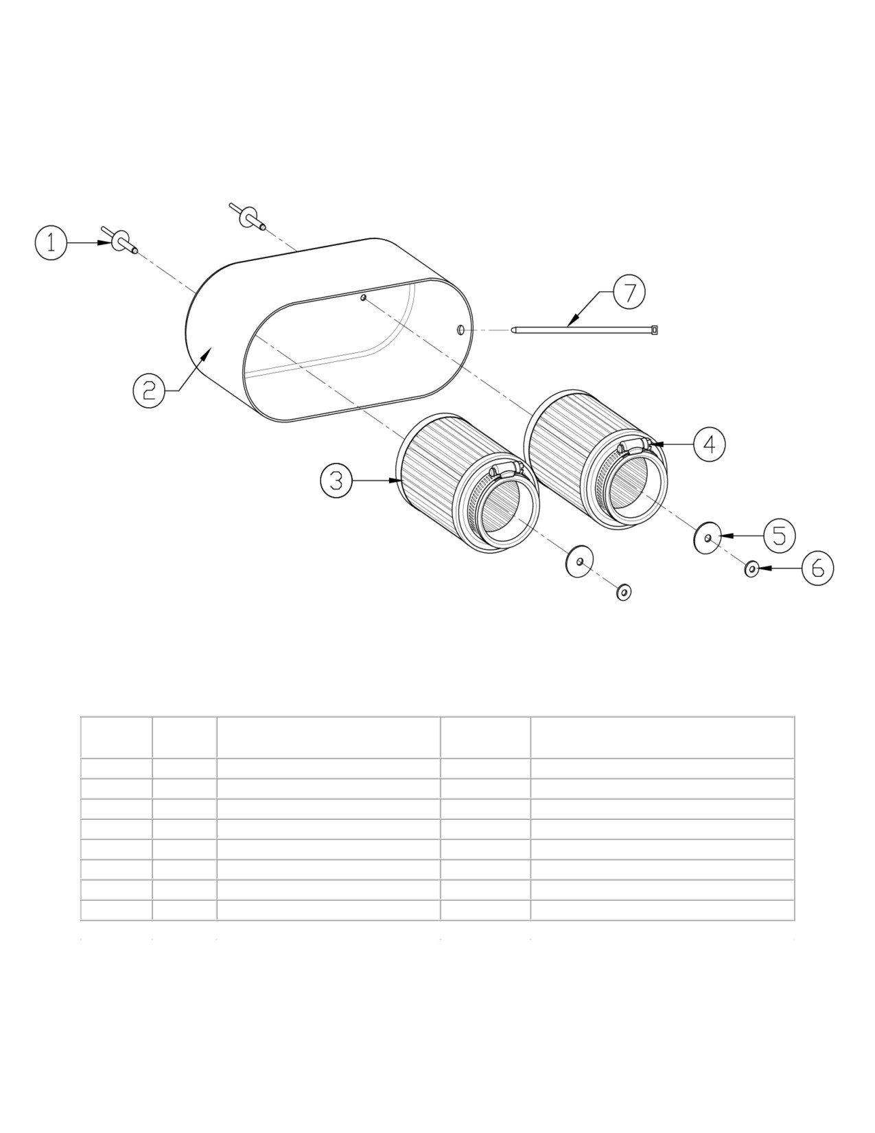
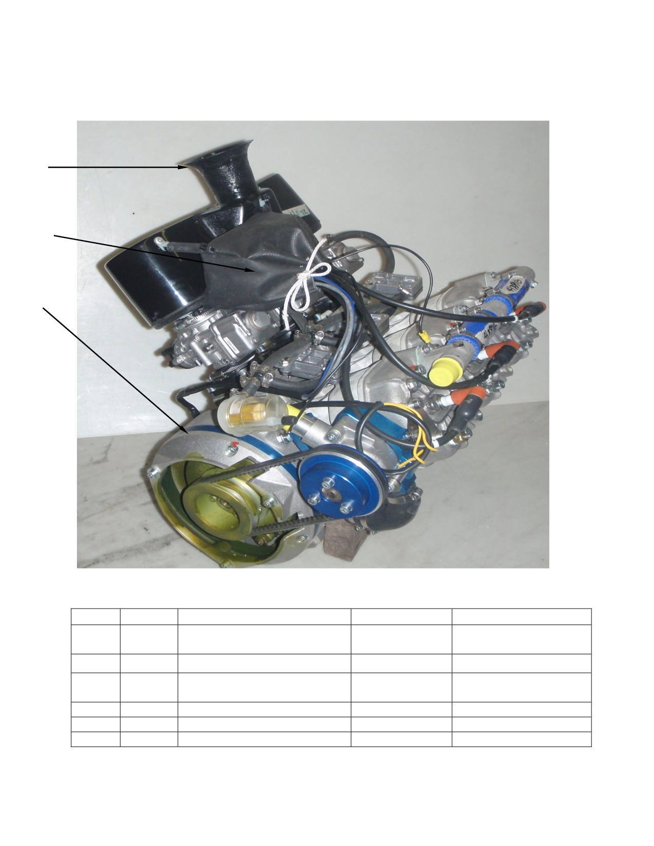
Hirth 55HP Air Box Assembly
Fig. No.
Qty
Designation
Neoteric
Remark
Part #
1
2
Rivet
2156
2
1
Fiberglass Air Box, Carbureted
5584
3
2
Air Filter
6622
Includes item 4
4
2
Hose Clamp
-
5
2
Large Washer
2516
6
2
Small Washer
2352
7
2
Wire Tie
2371
Safety tie
-
-
Air Box Assembly, Carbureted
5583
Includes item 1 - 7 as shown above
Form 17459 rev2
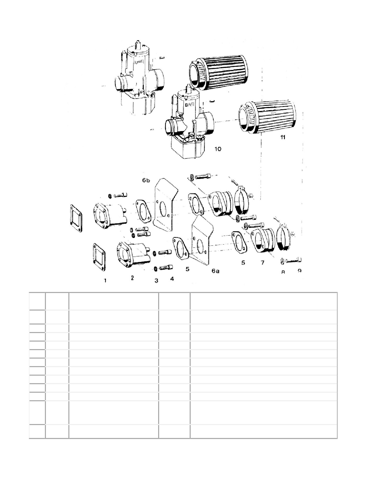
55HP Fuel Mixture, 2-Carb Sys
(2703)
Fig.
Qty
Description
Neoteric
Remark / Notes
No.
Part #
1
2
Gasket
7949
2
2
Intake manifold
7948
3
8
Serrated lock washer
6902
4
8
Cylinder screw
2292
Torque = 9.6 - 11 Nm (7.1 - 8.1 ft-lb)
5
4
Gasket
5454
6a
1
Heat shield plate, right
7950
6b
1
Heat shield plate, left
7951
7
2
Intake Boot
6567
8
4
Tab washer
7952
9
4
Cylinder screw
7953
Torque = 23 - 28 Nm (17 - 20.1 ft-lb)
10
2
BING carburetor
5333
Main Jet:160, Idle Jet:45,
Needle Jet: 2.72 Jet Needle 6P2
Pos:1, Air screw: 0.5-1
11
2
Air filter
6622
* See Form 16619 for Air filter system details
Form 17685 rev2
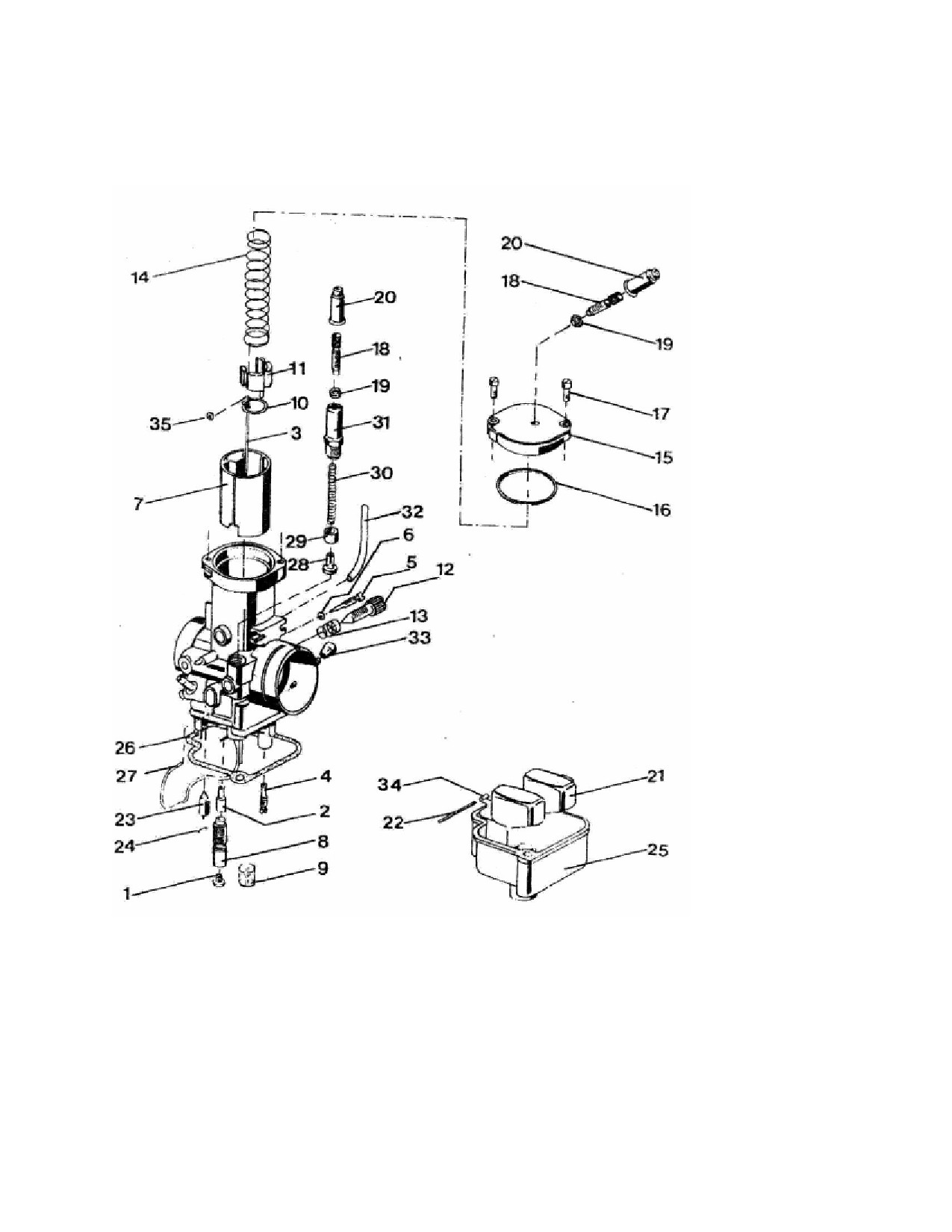
Carburetor 2703
Form 17686 rev2

55HP Hirth Bing Carburetor Parts
(2703)
Fig.
Neoteric
Qty
Description
Remark / Notes
No.
Part #
1
1
Main jet
-
2
1
Needle jet
-
See form 16642 for all Bing Jets
3
1
Jet needle
-
4
1
Idle jet
-
5
1
Idle Screw
7954
6
1
Idle Screw O-Ring
7955
7
1
Throttle slide
7956
8
1
Mixture tube
7957
9
1
Sieve Sleeve
7958
10
1
Bracket plate
6974
11
1
Spring Cup
7959
12
1
Adjusting screw
7960
13
1
Adjustment Screw Spring
7961
14
1
Slide Spring
7962
15
1
Cover plate
7963
16
1
Cover Plate O-Ring
7964
17
2
Cover Plate Screw
7965
18
1
Adjusting screw
6105
19
1
Nut
6106
20
2
Socket
6113
21
2
Float
7966
22
1
Float Pivot Pin
7967
23
1
Float Needle
7968
24
1
Float Needle Clip
7969
25
1
Float chamber
7973
26
1
Bowl Gasket
7974
27
1
Bowl Clip
7975
28
1
Choke Piston
7976
29
1
Choke Sleeve
7977
30
1
Choke Spring
7978
31
1
Choke housing
7979
32
2
Vent Tube
7980
33
1
Rubber cap for primer
7981
connection
34
1
Float chamber
7982
35
1
Jet Needle O-ring
7983
-
-
Rebuild Kit
6286
Includes fig. 6, 9, 16, 20, 22, 23, 26
Form 17687rev2
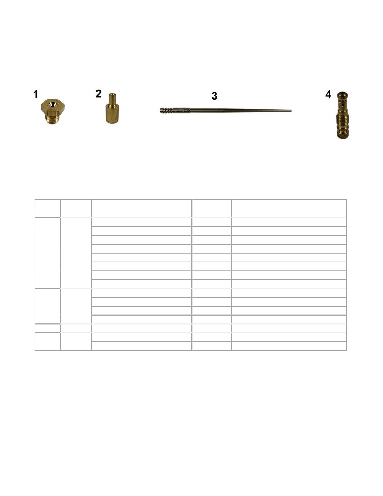
55HP Hirth Bing Carburetor Jets
(2703)
Fig.
Qty
Description
Neoteric
Remark / Notes
No.
Part #
Main Jet, 148
5759
Main Jet, 155
5474
Main Jet, 158
5473
Main Jet, 160
5876
1
1
Main Jet, 162
5890
Main Jet, 165
5891
Main Jet, 170
6196
Main Jet, 180
6195
Needle Jet, 2.62
5757
Needle Jet, 2.68
5758
2
1
Needle Jet, 2.7
5725
Needle Jet, 2.72
6177
3
1
Jet Needle, 6P2
6976
Idler Jet, 45
6519
4
1
Idler Jet, 50
6521
Form 16642 rev2
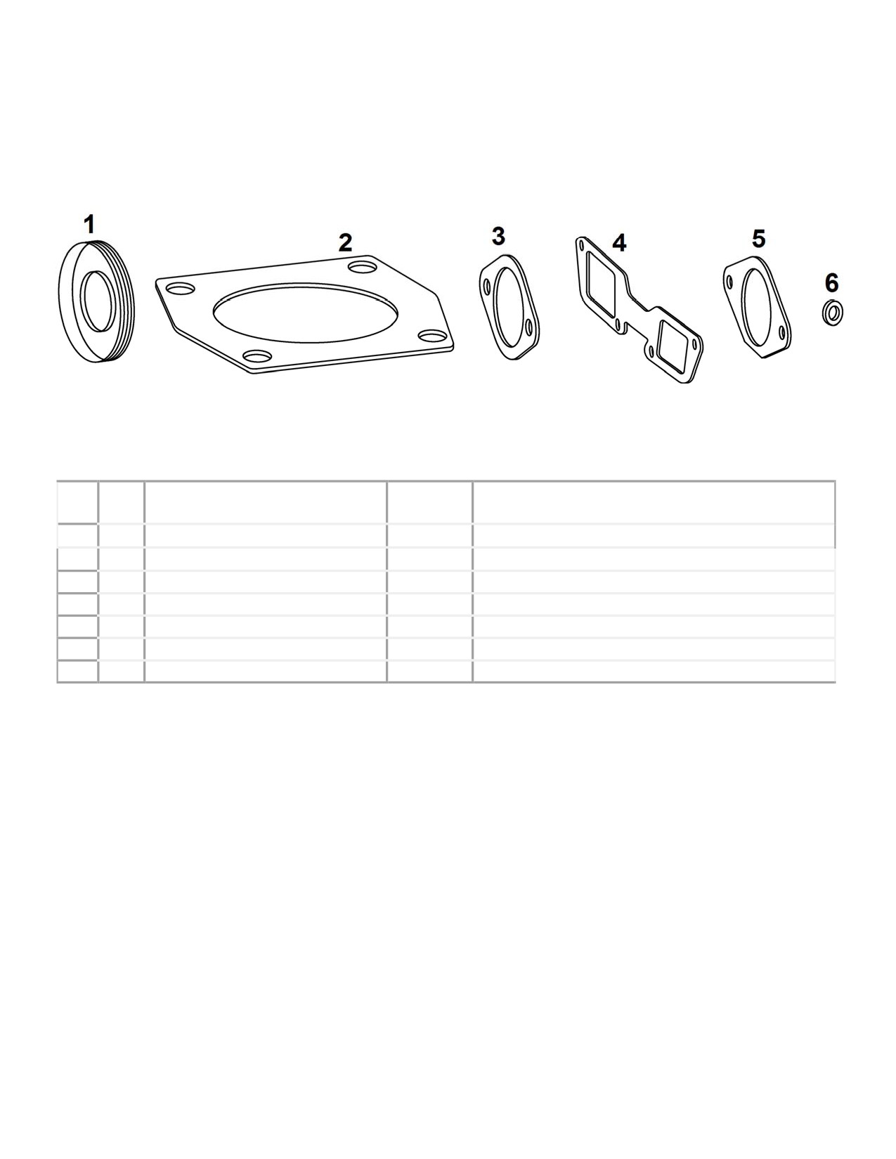
55HP Gasket Set
(2703)
Fig.
Neoteric
Qty.
Description
Remark / Notes
No.
Part #
-
1
55HP Gasket Set
5861
Includes Fig 1, 2, 3, 4, 5, 6
1
2
Crankshaft Seal
5453
2
2
Cylinder Base Gasket
3433
3
2
Exhaust Outlet Gasket
5245
4*
1
Single Carb Intake Gasket
-
* Not Used
5
2
Intake Boot Gasket, Oval
5454
6
2
Vacuum Nipple Gasket Washer
5629
Not Used
Form 17749 rev2
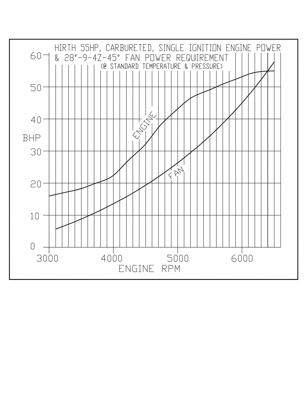
55HP Hirth Engine/Fan Power Requirement Graph
Form 17005 rev2
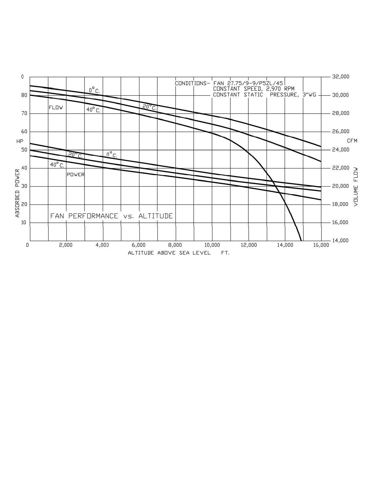
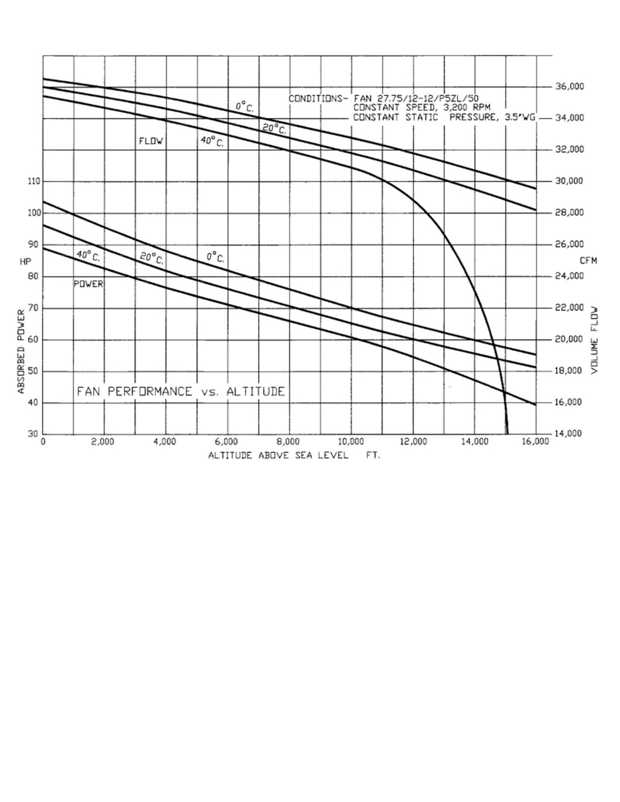
55HP Fan Altitude Performance Graph
Form 17751 rev2
HIRTH 3203 Carburated - 65 HP
HIRTH’s most popular engine. The 3203 produces more horsepower and torque per pound than any
other engine in its power class. Hirth 3203 is the forerunner in power plants for the heaviest
ultralight trainers, gyrocopters and light experimentals today.
3203 incorporates Al-Nikasil coated cylinders for superior performance and reliability. Al-Nikasil in
simple terms is a nickel based material, applied in a paste form, when superheated it becomes part
of the cylinder itself. Al-Nikasil provides for a super low coefficient of friction, reducing engine
heat and wear. The pistons and cylinders expand at the same rate thus providing for a seizure
resistant engine. 3203 crankshaft is 4130 chromemolly steel. Heads, cylinders, rings, block casting,
connecting rods and associated components are all of the highest grade alloys available today.
2706 - 65Hp engine shown with fan cooling
Technical Data:
Model:
3203 2 cycle, two cylinder in line
Carburetion:
Dual 38mm slide type or optional fuel injection
fan cooled
Fuel Pump:
Auxiliary external pneumatic
Bore:
2.99” [76 mm]
Lubrication:
Premix - 50:1 ratio or optional oil injection
Stroke:
2.72” [69 mm]
Rotation:
Counter clockwise, viewed from output end
Piston Diameter:
2.986” [75.84mm]
Ring Gap:
0.009” [0.23mm]
Cylinder Diameter:
2.991” [75.97mm]
Starter:
12 VDC electric, recoil or both/250 watt charging.
Displacement:
625 cc
Cooling:
Optional - Axial fan or free air cooled by prop.
Compression:
9.5 : 1
Ignition:
Single CDI (Capacitive discharge Ignition)
HP Output:
65hp [48.5 kW] @ 6300 rpm
Weight:
82 lbs. fan cooled including Elec. Start and exhaust
Torque:
56ft. lbs. [76 Nm] @ 5700 rpm
TBO
1000 Hrs. Rated at 75% power
*Optional Plugs: NGK BR8HS
Champion RL86C or #830
Engine
3203 - 65 HP FC
Ign. Timing @ 2000 Carbureted
16° BTC
Ign. Timing @ 2000 Fuel Injected
18° BTC
Spark Plug Heat VI
280
Spark Plug Gap
0.020-0.024
No. of Carburetors
Two
Carburetor ID #
Dellorto PHBE 34 BD 8
Main Jet
l60 : 155 & 158 Available
Idle Jet
40
Idle Screw
3/4 Turn Out
Jet Needle
K 35
Needle Jet
AB 268
Needle Position
1
Cold Start/Choke Jet
90
Do not exceed RPM
6600
Peak HP RPM
6300
HP @ Peak RPM
65
Peak Torque RPM
6000
Peak Torque Ft. Lb.
55
Maximum CHT
535° F
Maximum EGT @ full power
1256°F
Maximum EGT @ cruise RPM
1330°F
Spark Plug Denso
W24 FSR - U10*
Form 16013 rev3
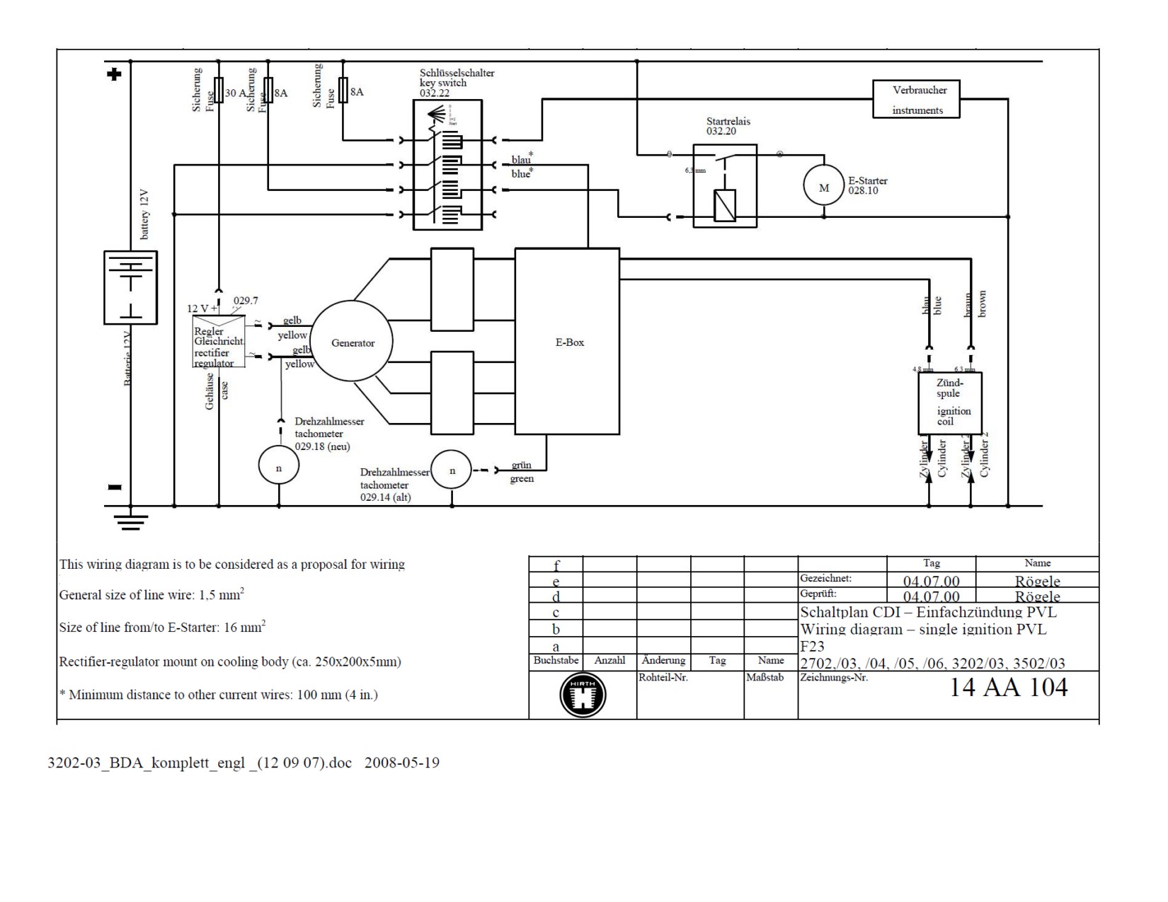
Form 17700 rev2
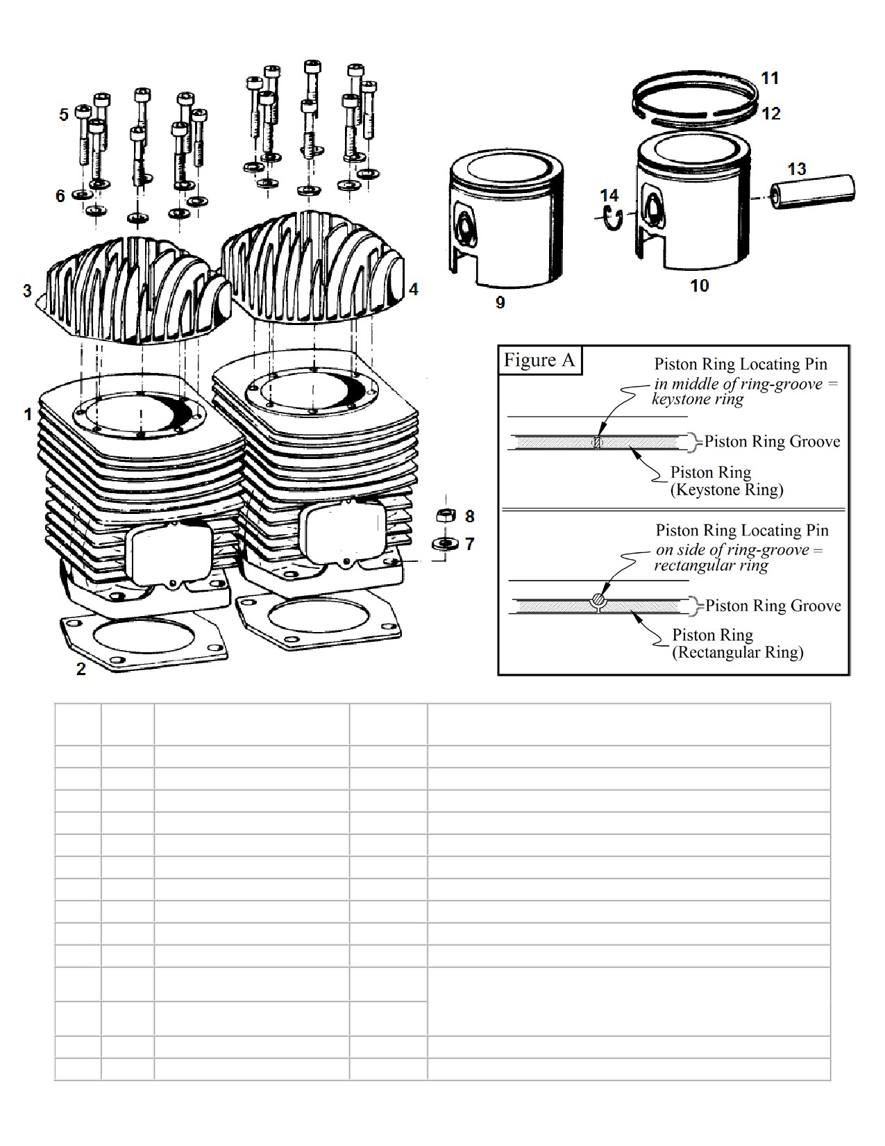
65HP Cylinder Single Ignition
Fig.
Neoteric
Qty.
Description
Remark / Note
No.
Part #
1
2
Cylinder
6099
2
2
Cylinder base gasket
5455
See Form 17368 for Gasket set
3
1
Rear Cylinder head
5457
4
1
Front Cylinder head
5458
5
16
Cylinder screw
6911
Torque = 9.6 - 11 Nm (7.1 - 8.1 ft-lb)
6
16
Washer
5994
7
8
Washer
6234
8
8
Hexagon head nut
6233
Torque = 23 - 26 Nm (17 - 19.2 ft-lb)
9
2
Piston Set
5450
Includes 10 - 14
10
-
Piston
7210
11
-
Keystone Piston-Ring
5452
* Examine locating pin position in both upper & lower
Ring-Grooves on piston to determine Ring type, as
12
-
Rectangular Piston-Ring
5451
shown in Figure “A”
13
Wrist Pin
5972
14
Retaining ring (circlip)
6301
Form 17276 rev2
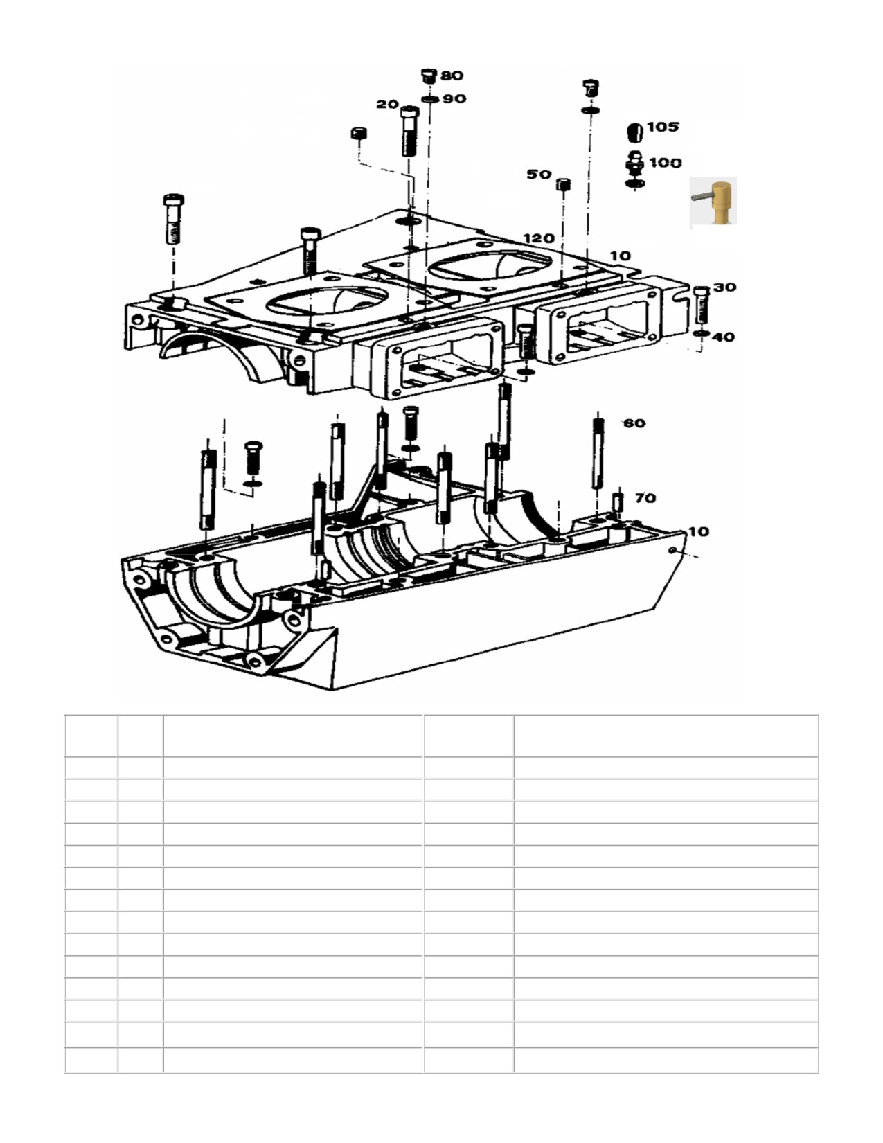
Spare part list - 65 HP Single Ignition
Crankcase 3203
90
110
Fig.
Neoteric
Qty.
Description
Remark / Notes
No.
Part #
10
1
Crankcase, complete
7164
Included Figures 60 - 70
20
3
Cylinder screw
7937
Torque = 23 - 25 Nm [17 - 18.4 ft-lb]
30
4
Cylinder screw
2289
Torque = 9 - 11 Nm [6.6 - 8.1 ft-lb]
40
4
Washer
6916
50
4
Threaded Pin Grub Screw
9003
Loctite 243
60
8
Stud screw
7163
Loctite 243
70
2
Plug tip
7936
Loctite 586
80
2
Cylinder screw
9004
Only 1 Required for Carbureted engines
90
2
Sealing ring, AL
5629
100
1
Pulse line / Crank Case vac. nipple
5630
Carburetor engines only.
105
1
Dust Cover / Boot
7208
110
Oil injection nipple
5490
Oil inj. Engines with fuel inj.
120
Cylinder Base Gasket
5455
See form 17749 for gasket set
-
Rubber Gasket Sealant
7842
Use as crankcase gasket
Form 17275 rev3
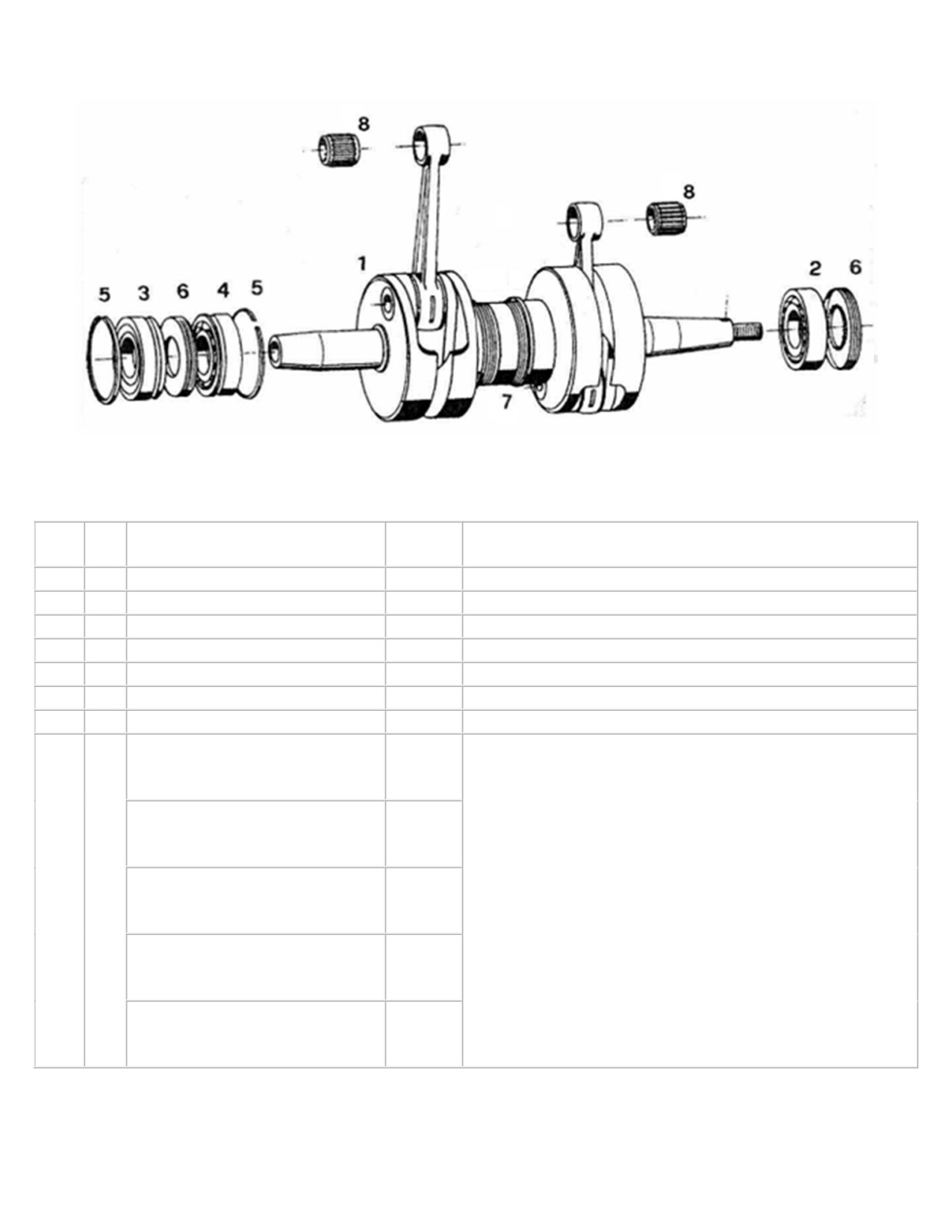
Crankshaft 3203
Fig.
Neoteric
Qty.
Description
Remark / Notes
No.
Part #
1
1
Crankshaft, complete
5449
Includes items 2 - 7
2
1
Deep groove ball bearing
5460
3
1
Deep groove ball bearing
5461
4
1
Deep groove ball bearing
5462
5
2
Circlip
7912
6
2
Shaft sealing ring
5453
7
1
Space ring
7913
Needle Bearing, Blue dot (#1)
7909
* Connecting Rods are Color-Coded with a Paint Dot on
the Piston end.
Needle Bearing, Yellow dot (#2)
6082
Engines built from 2010 onward also include a Number
Code next to the Paint Dot. The coding corresponds to the
8
2
correct Needle bearing size. (Approx 0.0003" [0.008mm]
graduation between each size)
Needle Bearing, Red dot (#3)
6083
Blue (#1) is the smallest and Green (#5) is the largest.
Connecting rods with a Red (#3) dot are most common.
Needle Bearing, White dot (#4)
5464
If the paint dot is missing and no number code can be
found, all bearings must be tried for the best fit.
Needle Bearing, Green dot (#5)
7910
Part 17756 rev2
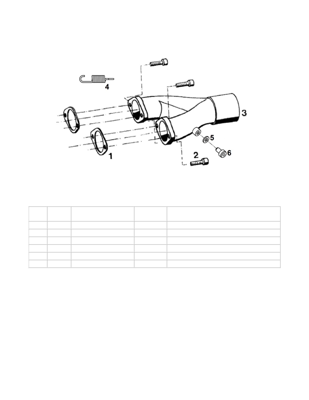
65HP Exhaust Header Pipe
(Y-Pipe)
Fig.
Neoteric
Qty.
Designation
Remark / Notes
No.
Part #
1
2
Exhaust gasket
5245
2
4
Cylinder screw
6932
Torque = 23 - 28 Nm (17 - 20.1 ft-lb)
3
1
Exhaust manifold
5548
Prepared for temperature meas.
4
4
Exhaust Spring
5421
5
2
Copper Washer
7077
6
2
M8x1x10 SHCS
6934
EGT Plugs; used when no EGT is installed
Form 16960 rev2
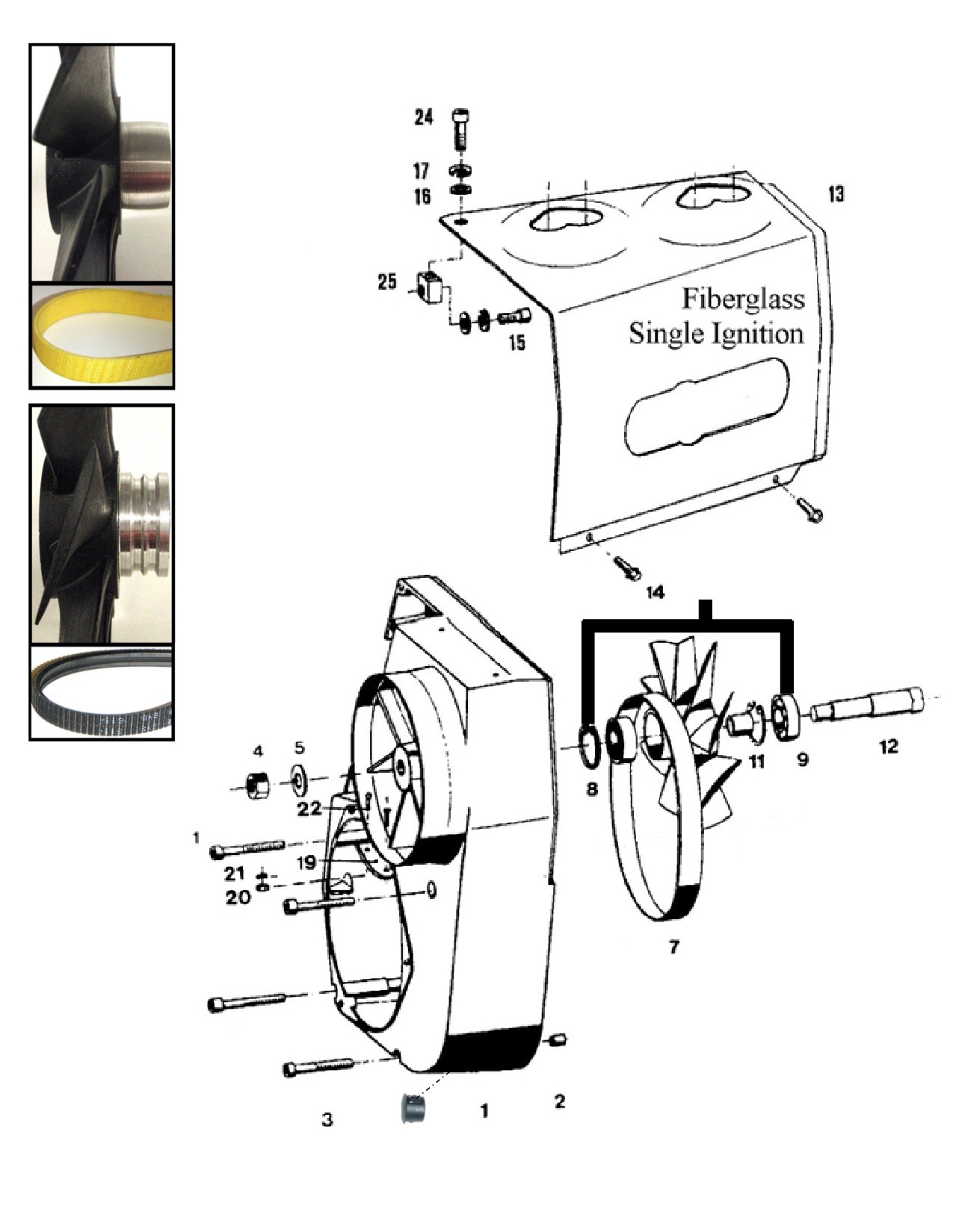
Fan cooling system 3203
* Flat Belt
Cooling Fan
(Old Style)
* Flat Belt
(Old Style)
Poly V Belt
Cooling Fan
(Current)
10
Poly V Flex
Belt
(Current)
NOTE:
If switching to poly V
belt, must change
sprocket as well.
Sprocket item #6 on
form 17282 below
Sprocket Part#6389
27
Form 17752 rev4

Fan cooling system 3203
Fig.
Qty.
Description
Neoteric Part No
Remark/Note
No.
Fan housing,
Includes Fig No.
1
1
9020
complete
4, 5, 6, 10*, 12, 19, 20, 21
2
3
Alignment sleeve
7939
3
4
Cylinder screw
3258
Torque = 6-8 ft lb. (9.6-11 Nm)
4
1
Hexagon head nut
6855
Torque = 20 ft lb. (27-30 Nm)
5
1
Washer
6856
*Used up to model year 2008
7*
1
Flat belt
3407
(Engine #901105 & Lower)
Currently used, from 2008 onward
7
1
Poly V Flex belt
6390
(Engine #901106 & Higher)
8
2
Locking ring
7940
Deep groove ball
9
2
6887
bearing
Incl. Pos. 8, 9, 11
Fan wheel Assy,
3408
10*
1
*Used up to model year 2008
Flat belt
(5879 - modified)
(Engine #901105 & Lower)
Incl. Pos. 8, 9, 11
Fan wheel Assy,
10
1
6391
Currently used, from 2008 onward
Poly V
(Engine #901106 & Higher)
11
1
Bushing
7941
12
1
Eccentric shaft
6857
13-B
1
Air guide cowl - SI
5324
Single ignition
14
2
Thread screw
5997
15
1
Cylinder screw
6901
Torque = 6-8 ft lb. (9.6-11 Nm)
16
2
Washer
6916
17
2
Spring ring
5999
19
1
Metal plate
6183
20
2
Hexagon head nut
2694
21
2
Washer
7942
22
2
Screw
2693
23-A
2
Rubber grommet
For dual ignition engines
23-B
2
Rubber grommet
9021
For single ignition engines
24
1
Cylinder screw
5998
Torque = 6-8 ft lb. (9.6-11 Nm)
Air guide mounting
25
1
6928
block
26
1
Sheet
5981
Not on Sketch
27
1
Hole Plug
2449
Covers Hole In Housing
Form 17753 rev3
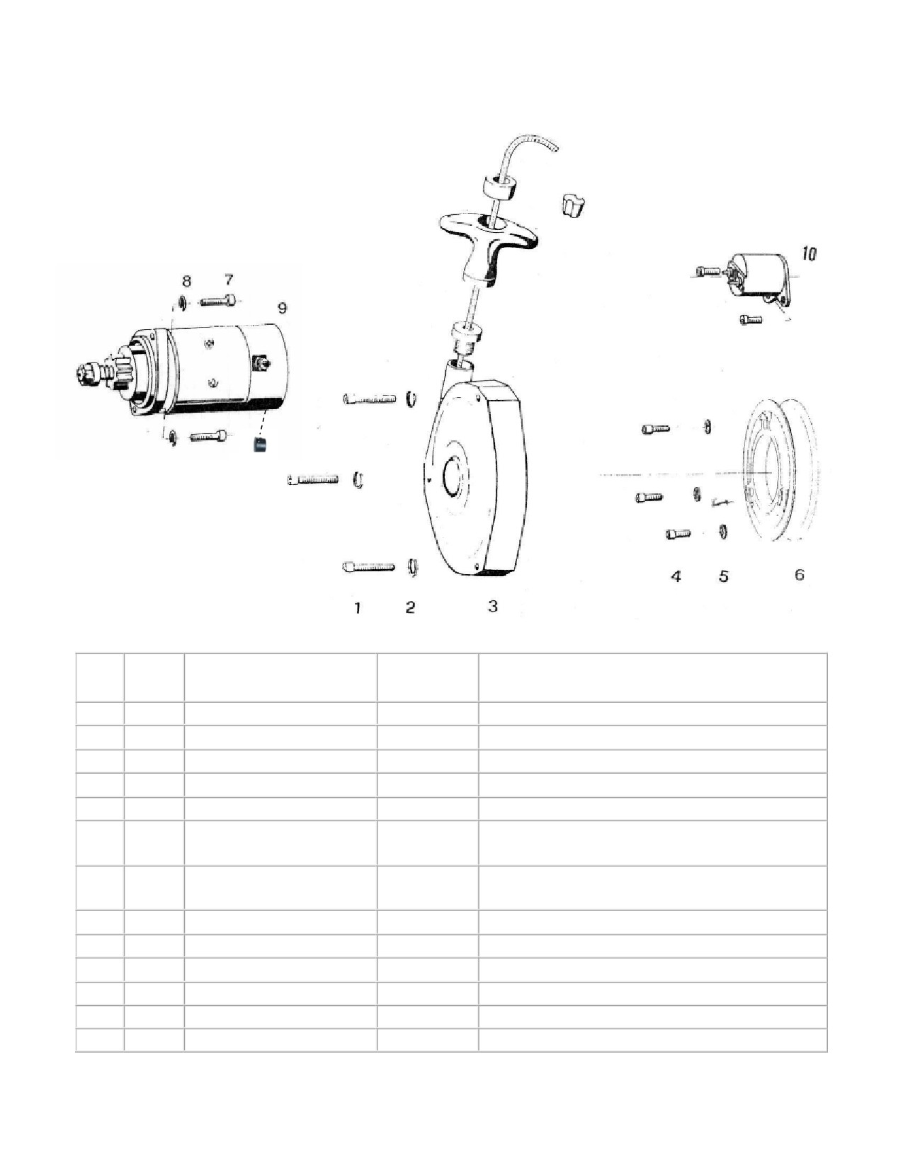
65HP Starting Device
(3203)
11
Fig.
Neoteric
Qty.
Description
Remark/Note
No.
Part #
1
3
Cylinder screw
6911
Torque = 9.6 - 11 Nm (7.1 - 8.1 ft-lb)
2
3
Spring ring
6940
3
1
Starter, mounted
5267
4
3
Cylinder screw
7944
Torque = 23 - 28 Nm (17 - 20.7 ft-lb)
5
3
Tab washer
5995
6*
Driving dog with starter,
*Used up to model year 2008
6189
Flat
(Engine #901105 & Lower)
6
1
Driving dog with starter,
Currently used, from 2008 onward
6389
Poly-V
(Engine #901106 & Higher)
7
2
Cylinder screw
2348
Torque = 23 - 28 Nm (17 - 20.7 ft-lb)
8
2
Tab washer
5995
9
1
Starter
6982
Old Starter 5545
-
1
Alternative Starter
7563
Replacement for Customers
10
1
Starter Solenoid
5417
11
1
Starter Hole Plug
9172
Used to plug drain hole in starter
Form 17282 rev3
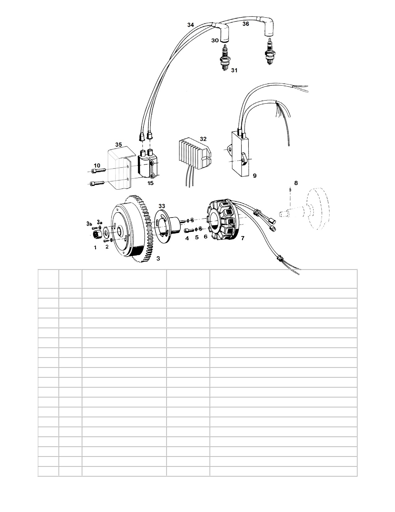
55/65HP Ignition System
Fig.
Qty.
Description
Neoteric
Remark/Notes
No.
Part #
1
1
Hexagon head nut
6939
Torque = 140 - 150 Nm (103.3 - 110.6 ft-lb)
2
1
Washer
7196
3
1
Flywheel with gear ring
7984
Includes fig. 3a, 3b, 33
3b
2
Low Profile S.H.C.S.
9697
4
2
Cylinder screw
7182
5
2
Washer
5994
6
2
Washer
6936
Torque = 4 - 4.5 Nm (3 - 3.3 ft-lb)
7
1
Stator plate complete
5591
8
1
Flywheel alignment pin
7985
9
1
CDI - Box
5664
Mounted with silicone
10
2
Coil Mounting Screw
2469
15
1
Ignition coil
5682
Includes fig. 15
30
2
Spark plug cap
5827
31
1
Spark plug
5668
Do not mix spark plug types
32
1
Voltage Regulator
5338
33
1
Magnet Support
5724
34
1
Spark plug lead, short
5666
Wire only; does not include fig. 30
36
1
Spark plug lead, long
5665
Wire only; does not include fig. 30
-
-
Spark Plug lead set
5661
Includes fig. 30, 34, 36
Form 17683 rev2
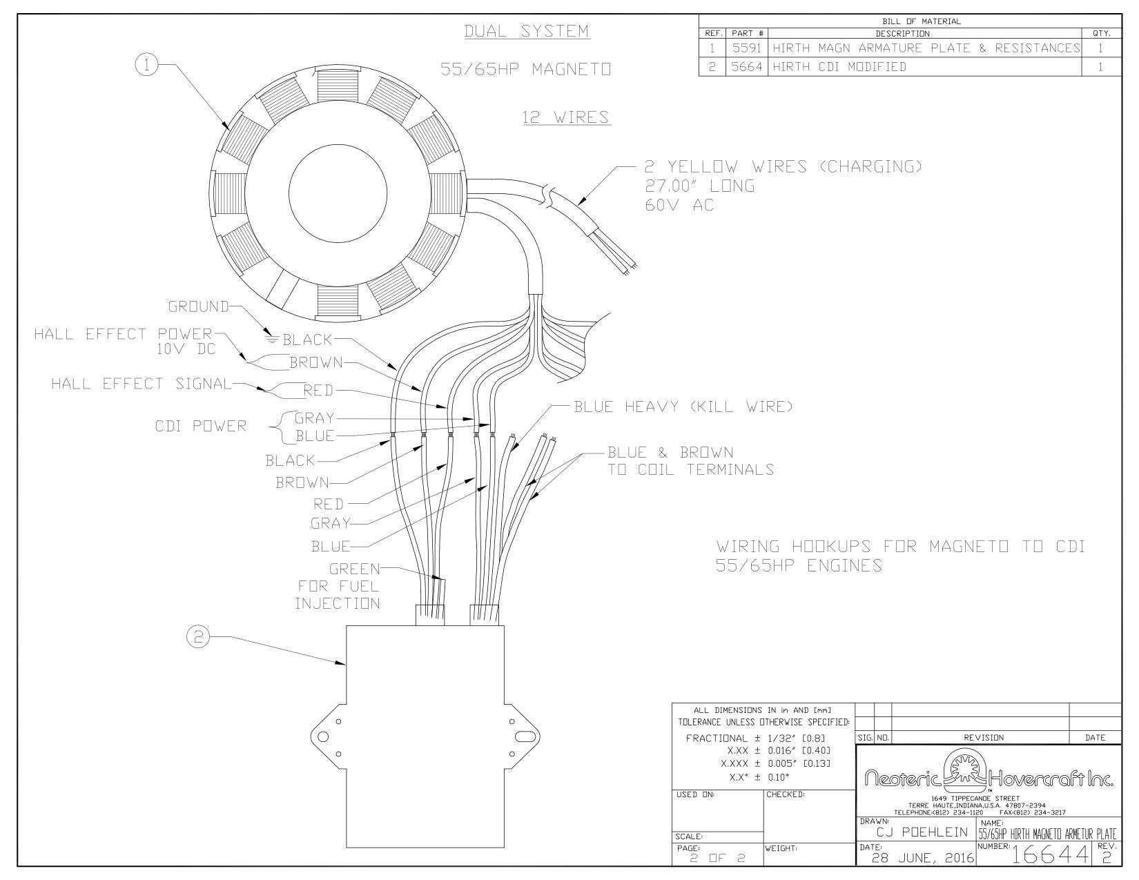
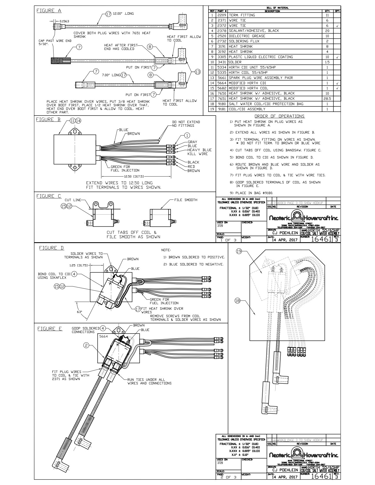
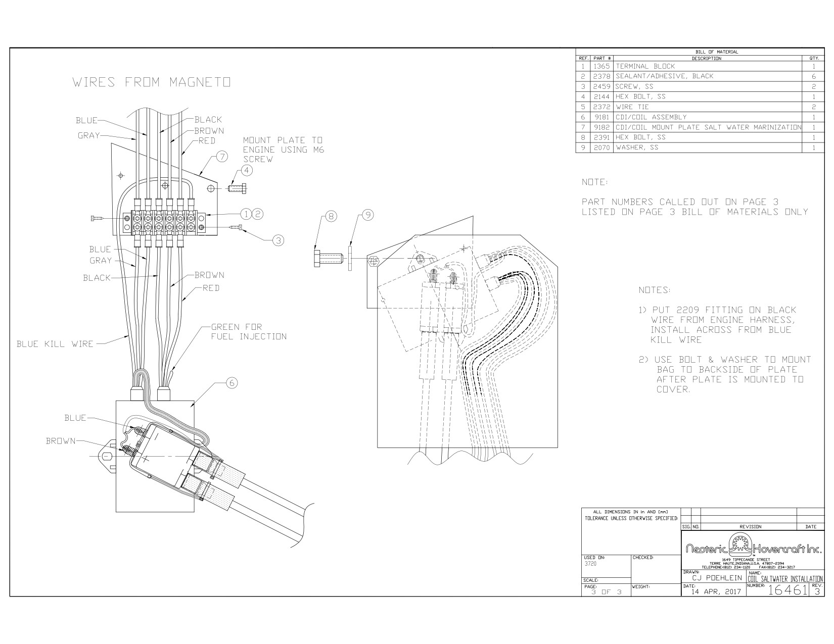
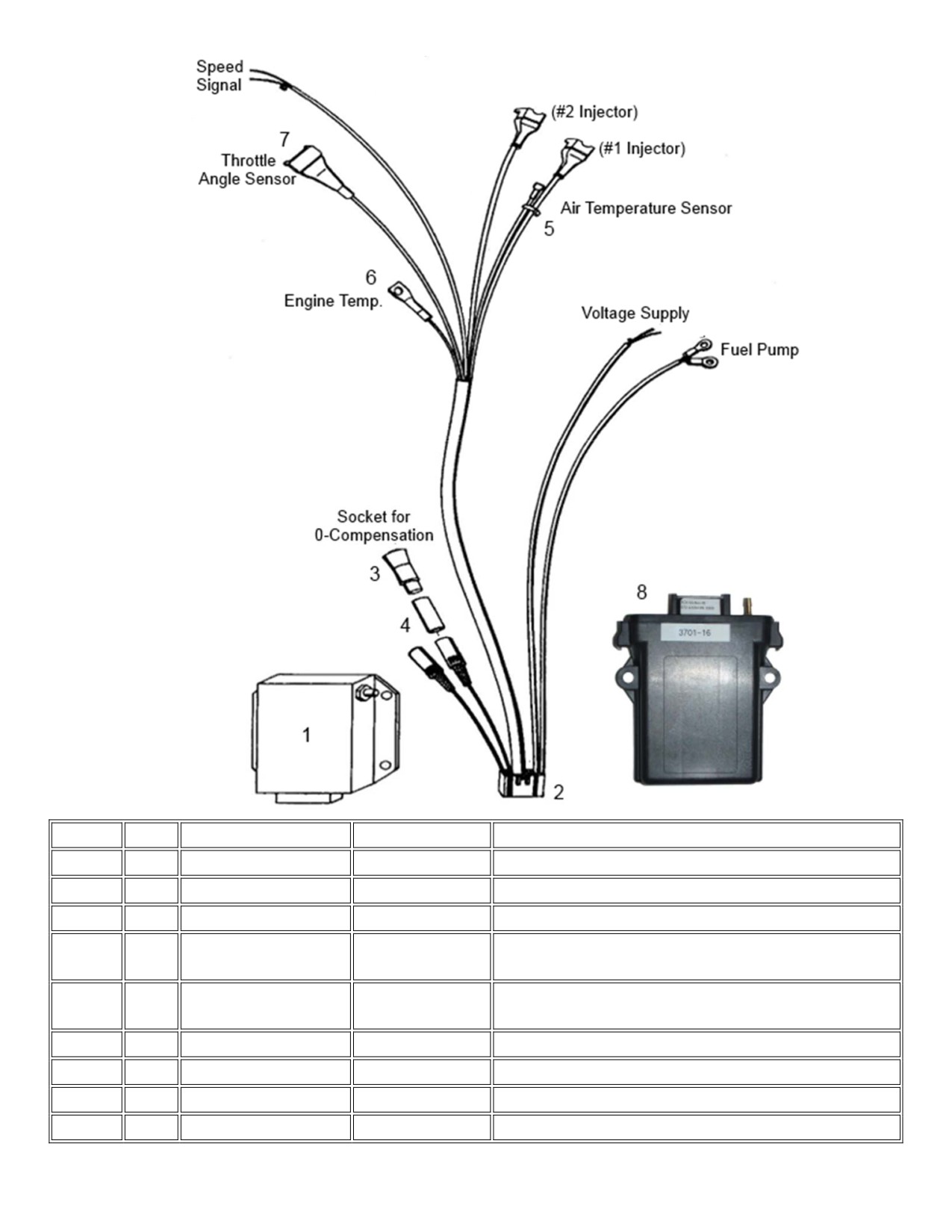
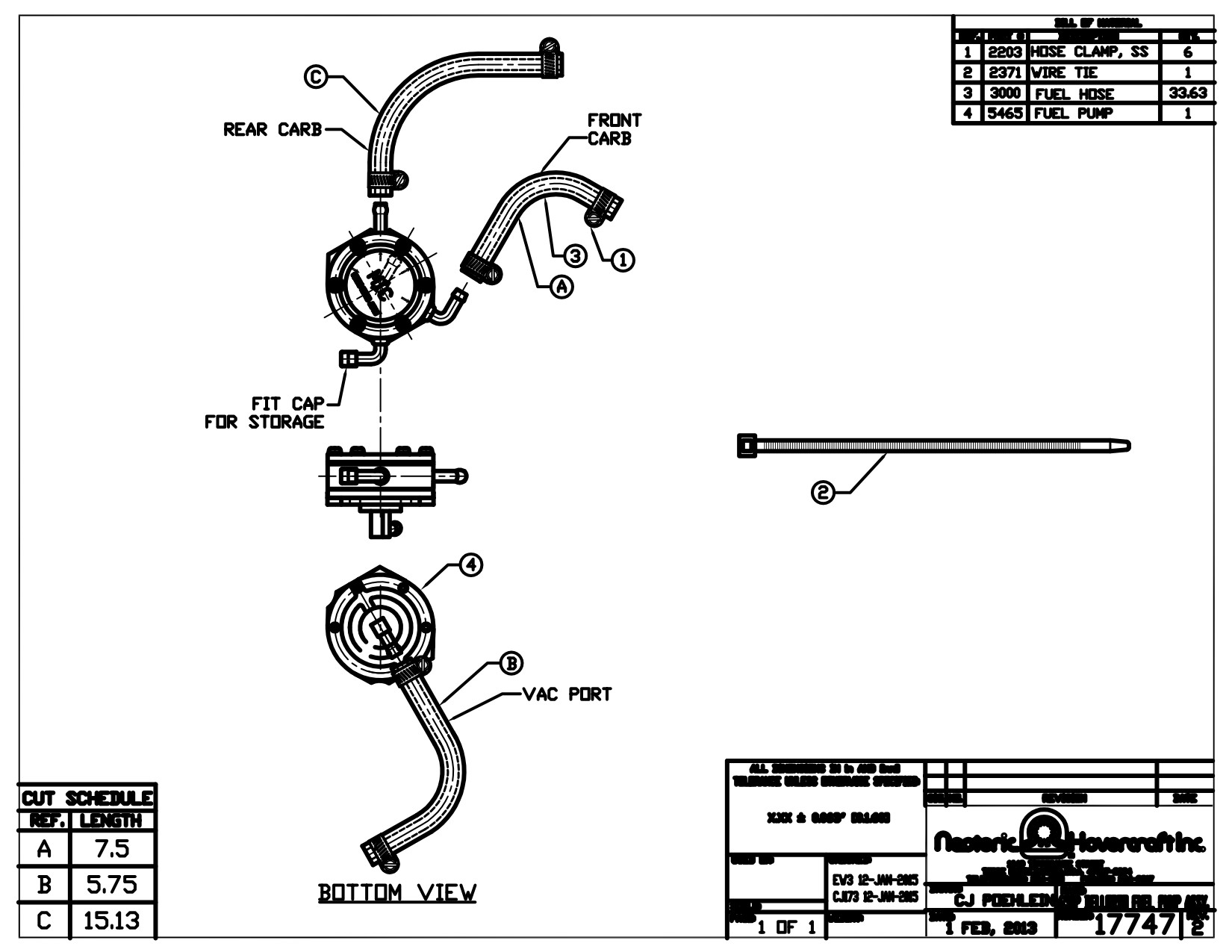
2-Cylinder Fuel Injection Electrical System
Fig.No.
Qty
Description
Neoteric Part #
Note
1
1
Red Computer Box
5328
Used on Early HoverTrek Models
2
1
Cable harness, Red
6235
Harness for Red Computer Box
2
1
Cable harness, Black
6237
Harness for Black Computer Box
3
1
0-compensation plug
7205
Used when optional manual enrichment device not
used -
4
1
Shrink tube
3192
Place on plug with 3 wires (cable colors red, blue,
black) 60 denotes length in mm
5
1
Air Temp Sensor
7525
6
1
Engine Temp Sensor
7526
Attached to Engine Block
7
1
Throttle Pos. Sensor
7567
8
1
Black Computer Box
6382
Used on Current HoverTrek Models
Form 16959 rev3
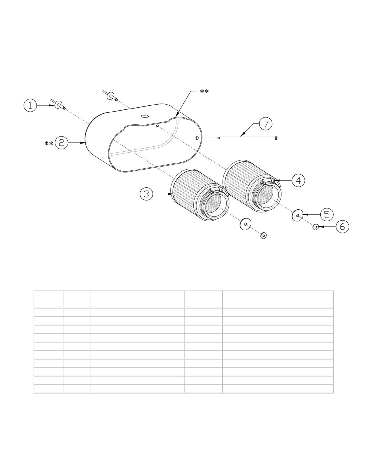
Hirth HT4 Air Box Assembly
Cutouts on FI Air Boxes Only;
Carbureted Air Boxes have no Cutouts
Fig. No.
Qty
Designation
Neoteric
Remark
Part #
1
2
Rivet
2156
2
1
Fiberglass Air Box, Carbureted
5584
2
1
Fiberglass Air Box, FI
7764
3
2
Air Filter
6622
Includes item 4
4
2
Hose Clamp
-
5
2
Large Washer
2516
6
2
Small Washer
2352
7
2
Wire Tie
2371
Safety tie
-
-
Air Box Assembly, Carbureted
5583
Includes item 1 - 7 as shown above
-
-
Air Box Assembly, FI
7765
Includes item 1 - 7 as shown above
Form 16619 rev3
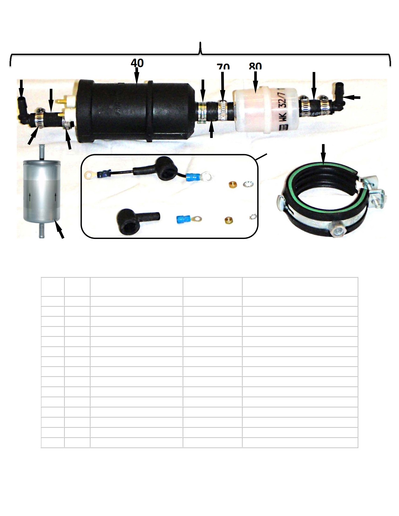
Hirth Fuel System
130
90
150
50
10
100
110
60
20
30
120
140
Fig.
Neoteric
Qty.
Description
Remark /Notes
No.
Part #
10
1
Fuel Line
6335
20
3
Screw/Band Hose Clamp
2203
30
1
Pinch Hose Clamp, Sm
5993
40
1
Electric Fuel Pump
6414
50
1
Pinch Hose Clamp, Lg
5986
60
1
Fuel Line
6334
70
1
Gapless Hose Clamp
6943
80
1
Fuel Filter
5372
90
3”
Fuel Line
3193
100
1
Large Elbow
2674
110
1
Fuel Pump Holder
6336
120
1
Fuel Pump Connection Kit
6628
130
-
Fuel Pump Assy
6666
Includes Fig No. 10 - 120
140
1
Micro Fuel Filter
5373
150
1
Small Elbow
2438
Form 17698 rev2
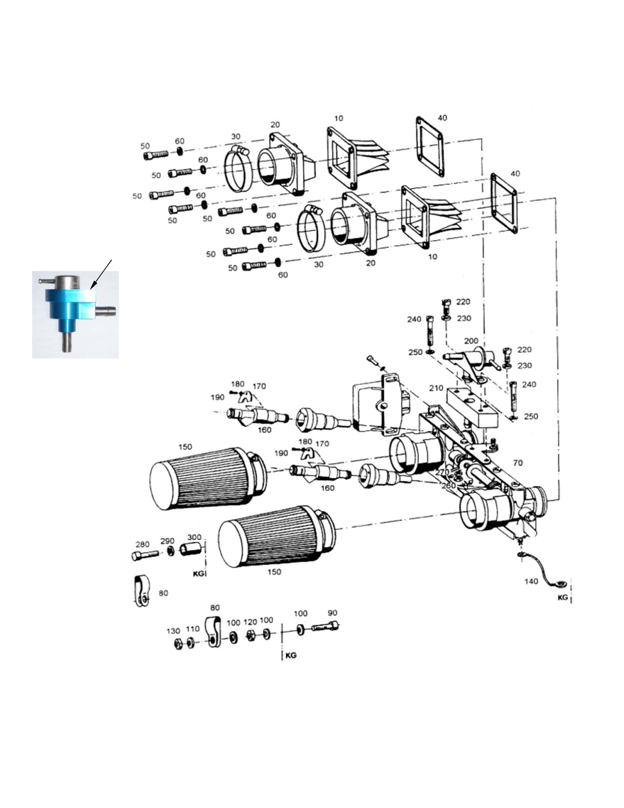
Fuel Injection /Fuel mixture 3203
200
Form 16021 rev3

Hirth 65HP Fuel Injection / Fuel mixture
Fig.
Neoteric
Qty.
Description
Remark / Notes
No.
Part #
10
2
Reed valve
7203
20
2
Intake manifold
6568
30
2
Hose clamp
9008
40
2
Gasket
5463
50
8
Cylinder screw
2292
Torque = 9.6 - 11 Nm (7.1 - 8.1 ft-lb)
60
8
Washer
6916
70
1
Throttle manifold
5594
80
2
Clamp
6929
90
1
Cylinder screw
6901
Torque = 9.6 - 11 Nm (7.1 - 8.1 ft-lb)
100
3
Washer
6916
110
1
Washer
5996
120
1
Hexagon head nut
9009
130
1
Hexagon head nut, self.
5572
140
1
Ground cable
6454
150
2
Air filter
6622
6904
*Used up to May-2011
160
2
Fuel Injector, Old Style
(Engine #902754 & Lower)
6903
Currently used, from May-2011 onward
160
-
Fuel Injector, New Style
(Engine #902754 & Higher)
170
2
Injector Holding plate
9010
180
2
Washer
9011
190
2
Cylinder screw
9012
Loctite 243
7188
Shown in illustration;
200
-
Pressure regulator, Old Style
*Used up to May-2011
(Engine #902754 & Lower)
7932
200
1
Pressure regulator, New Style
Currently used, from May-2011 onward
(Engine #902754 & Higher)
200
-
Pressure regulator, Replacement
7279
Compatible with both old & new styles
210
1
Pressure regulator holder, complete
9013
220
2
Cylinder screw
7189
Torque = 9.6 - 11 Nm (7.1 - 8.1 ft-lb)
230
2
Washer
6916
240
2
Cylinder screw
9014
Loctite 243
250
2
Washer
6936
260
2
Hexagon head nut
9015
270
2
Washer
9016
280
1
Cylinder screw
9017
290
1
Washer
6936
300
1
Bushing
6935
Form 16022 rev3
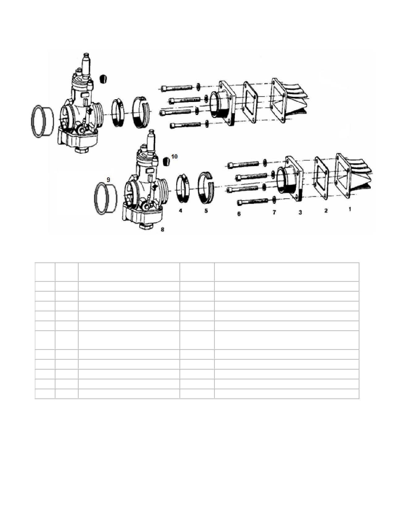
65HP Hirth Carburetor / Fuel mixture
(3203)
Fig
Neoteric
Qty.
Description
Remark/Note
No.
Part #
1
2
Reed valve
7203
2
2
Gasket
5463
3
2
Intake manifold/carb flange
6568
4
2
Hose clamp
9018
5
8
Rubber
9019
6
8
Cylinder screw
Torque = 9.6 - 11 Nm (7.1 - 8.1 ft-lb)
7183
Loctite 243
7
2
Washer
6916
8
1
Dellorto Carburetor 65HP Front
9264
See Form 17754 / 17755 for Carb Parts
8
1
Dellorto Carburetor 65HP Back
9265
9
2
Protective stopper
7207
10
Hirth Rubber Socket
7208
Form 17286 rev3
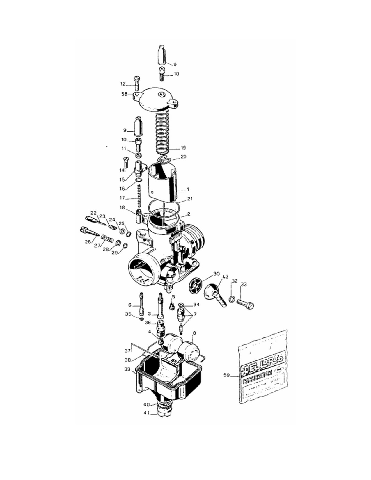
Carburetor (Dellorto) PHBE 34
Form 17754 rev2

Carburetor (Dellorto) F 33 A (PHBE 34 BD 6832)
Fig.
Neoteric
Qty.
Description
Remark/Note
No.
Part #
1
1
Throttle slide
9022
2
1
Jet needle, K36
6563
3
1
Needle jet
-
4
1
Main jet
-
See Form # 17367 for all Dellorto Jets
5
1
Idle jet, 65
9023
6
1
Cold start / Choke jet
7788
7
1
Float valve
9024
8
1
Float
6909
9
2
Rubber cap
6113
*Included in 7828 Kit
10
1
Choke Cable Adjustment
7828
*Must Purchase 7828 Kit
11
1
Choke Cable Adjustment Locknut
7828
*Must Purchase 7828 Kit
12
2
Top Cover Screw
9027
14
1
Choke Support Screw
9028
*Must Purchase 7828 Kit
15
1
Choke Support Casting
9029
*Must Purchase 7828 Kit
16
1
Choke Support O-ring
7828
Included in Pos. 59
17
1
Choke Valve Spring
9030
*Must Purchase 7828 Kit
18
1
Choke valve
7828
*Must Purchase 7828 Kit
19
1
Throttle Slide Spring
9025
20
1
Bracket plate
6973
21
1
Top Cover O-Ring
9026
Included in Pos. 59
22
1
Mixture Adjustment Screw
9031
23
1
Mixture Adjustment Spring
9032
24
1
Mixture Adjustment Washer
9033
25
1
Mixture Adjustment O-ring
-
Included in pos. 59
26
1
Idle Adjustment Screw
9034
27
1
Idle Adjustment Spring
9035
28
1
Idle Adjustment Washer
9036
29
1
Idle Adjustment O-ring
-
Included in Pos. 59
30
1
Fuel Inlet Filter
9037
32
1
Fuel Inlet O-ring
-
Included in Pos. 59
33
1
Fuel Inlet Screw
9038
34
1
Needle Valve Gasket Washer
-
Included in Pos. 59
35
1
Cold Start / Choke O-ring
-
Included in Pos. 59
36
1
Main jet holding screw
9039
37
1
Float Pivot Pin
9040
38
1
Sealing for float chamber
9296
Included in Pos. 59
39
1
Float Bowl
9041
40
1
Float Bowl Gasket Washer
7213
Included in Pos. 59
40
1
Float Bowl Gasket O-Ring
2739
Optional Replacement For Washer
41
1
Float Bowl Nut
9042
42
1
Fuel Inlet Nipple
6114
58
1
Carburetor Top Cover
9043
Includes Pos.
59
1
Gasket set
5468
16,21,25,29,32,34,35,38,40
Form 17755 rev4

65HP (PHBE) Dellorto Carb Jets
Parts List
Neoteric
Qty.
Description
Remark / Note
Part #
Main Jet, 155
5443
Main Jet, 142
5444
Main Jet, 145
5467
Main Jet, 160
5863
Main Jet, 150
9294
Main Jet, 158
6193
1
Main Jet, 165
9295
Main Jet, 170
8207
Main Jet, 162
5864
Main Jet, 175
9598
Main Jet, 180
9599
Main Jet, 190
9374
Main Jet, 200
9878
1
Idle Jet, 40
9817
1
Idle Jet, 65
9023
1
Cold Start / Choke Jet, 90
7788
Atomizer / Needle Jet, AB/265
9069
Atomizer / Needle Jet, AB/266
5726
1
Atomizer / Needle Jet, AB/262
5760
Atomizer / Needle Jet, AB/268
6194
1
Jet Needle, K35
9292
1
Jet Needle, K36
6563
Form 17367 rev2
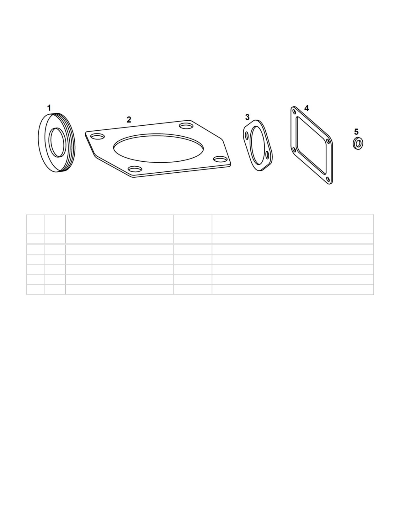
65HP Gasket Set
(3203)
Fig.
Neoteric
Qty.
Description
Remark / Notes
No.
Part #
-
1
65HP Gasket Set
7988
Includes Fig 1, 2, 3, 4, 5
1
2
Crankshaft Seal
5453
2
2
Cylinder Base Gasket
5455
3
2
Exhaust Outlet Gasket
5245
4
1
Single Carb Intake Gasket
5463
5
2
Vacuum Nipple Gasket Washer
5629
Form 17368 rev2
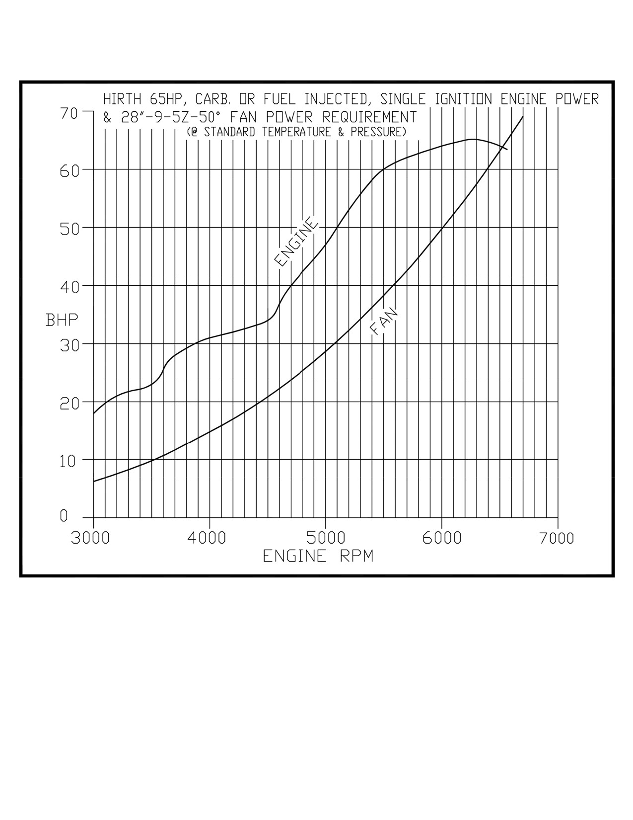
65HP Hirth Engine/Fan Power Requirement Graph
Form 17757 rev2
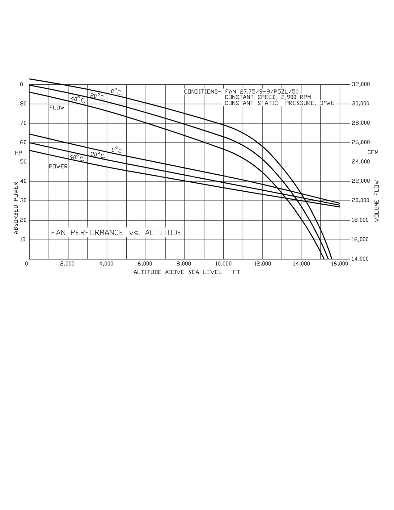
65HP Fan Altitude Performance Graph
Form 17758 rev2
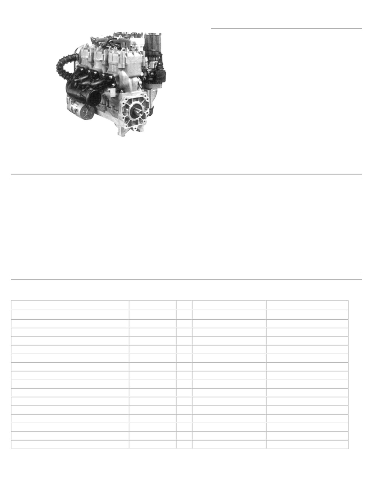
3701- 100Hp
The 3701 is Hirth's first offering of a water-cooled
engine for the aircraft market.
A narrow profile and single tuned exhaust used for
all 3 cylinders allows the 3701 to be used in compact
engine compartments. Pistons fire 120 degrees apart
resulting in very quiet & smooth operations.
3701 incorporates Al-Nikasil coated cylinders for
superior performance and reliability. Nikasil provides
for a super low coefficient of friction, reducing engine
heat and wear. The pistons and cylinders expand at the
same rate thus providing for a seizure resistant engine.
3701 crankshaft is 4130 chromemolly steel. Heads,
3701- engine shown with dual ignition and 90 degree exhaust manifold
cylinders, rings, block casting, connecting rods and
associated components are all of the highest grade
alloys available today.
Carburetion:
3 dellorto carbs
Technical Data:
Old Option: Electronic suction pipe fuel injection
Model:
3701 - 2 cycle, three cylinder inline
Fuel Pump:
3 diaphram pumps (1 for each carb)
Reed valve induction.
Old Option:
90 PST 12VDC electric fuel pump.
Bore:
76 mm
Lubrication:
Premix -40:1 or optional oil injection
Stroke:
69 mm
Displacement:
939 cc
Rotation:
Counter clockwise, viewed from output end
Compression:
9.5 : 1
12 VDC electric / 240 watt generator
Starter/Generator:
HP Output:
100hp @ 6000 rpm
Liquid cooled 50:50 mixture of glycol (anti freeze)
Peak Torque:
88 ft. lbs. @ 5500 rpm
Cooling:
& water
Ignition:
Single CDI (Capacitive Discharge Ignition)
108 lbs, including complete exhaust & starter
TBO
1,000 Hrs. Rated at 75% power
Weight:
Spark Plugs: NKG BR9HS
3701 TECHNICAL DATA
Fuel Injected Engine
3701S--100Hp
Carbureted Engine
Ign.Timing@2000 - Fuel injected
18°
Ign. Timing@2000
16°
Spark Plug Heat VI.
280
No. of Carburetors
3
Spark Plug Gap
0.020-0.024
Carburetor ID #
Dellorto PHBE 34 BD8
No. of Injectors
Three
Main Jet
165
Do Not Exceed RPM
6300
Idle Jet
50
Peak HP RPM
6000
Needle Jet
AB 265
HP @ Peak RPM
100
Needle Position
#1 Top
Peak Torque RPM
5500
Needle #
K43
Peak Torque Ft.Lb.
85
Float
8.5
Maximum CHT
390°F
Idle Screw
3/4 Turn Out
Maximum EGT @ full power
1150°F
Cold Start/ Choke Jet
90
Maximum EGT @ cruise power
1230°F
Maximum coolant temperature
220°F
Minimum coolant temperature
160°F
Form 16016 rev2
f
Tag
Name
e
03.07.01
Rögele
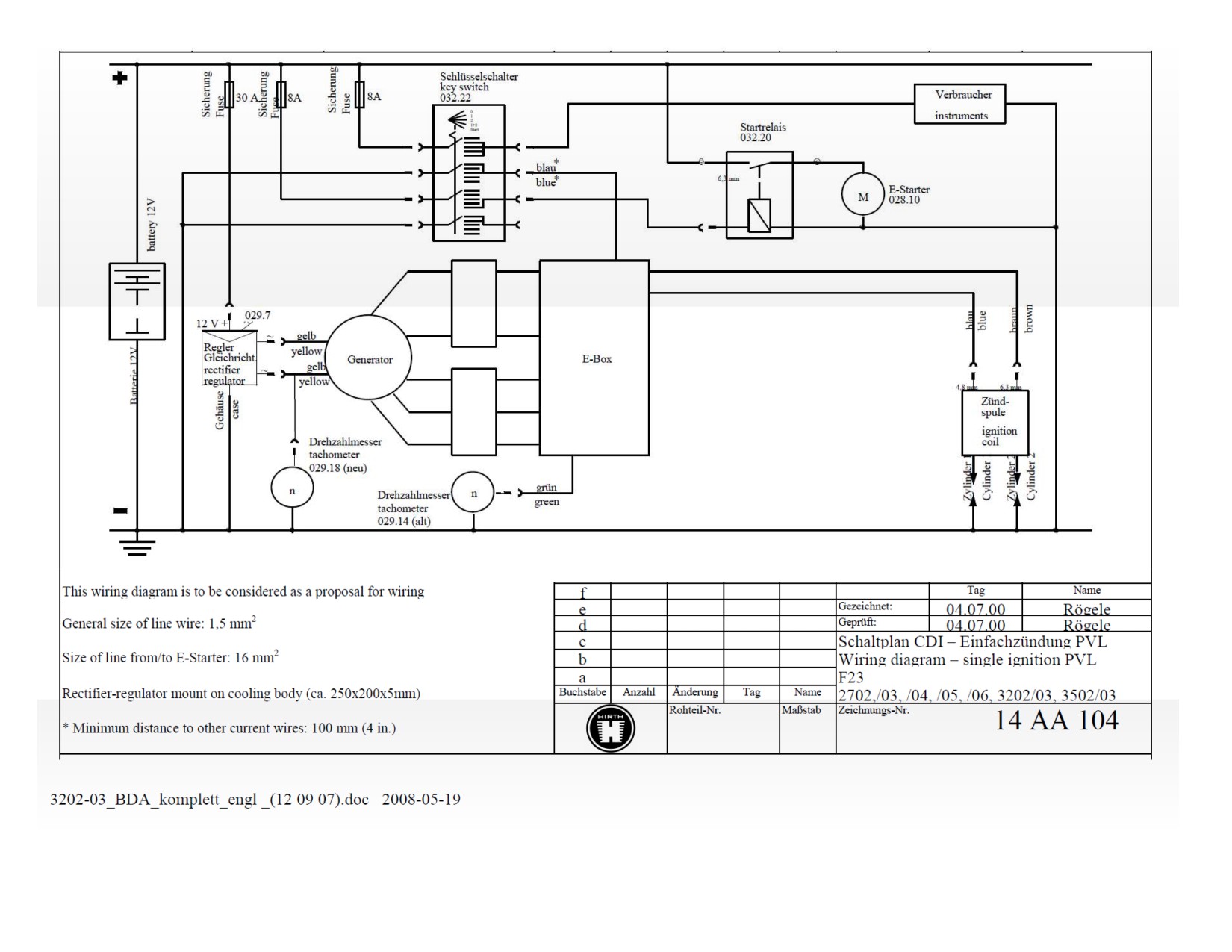
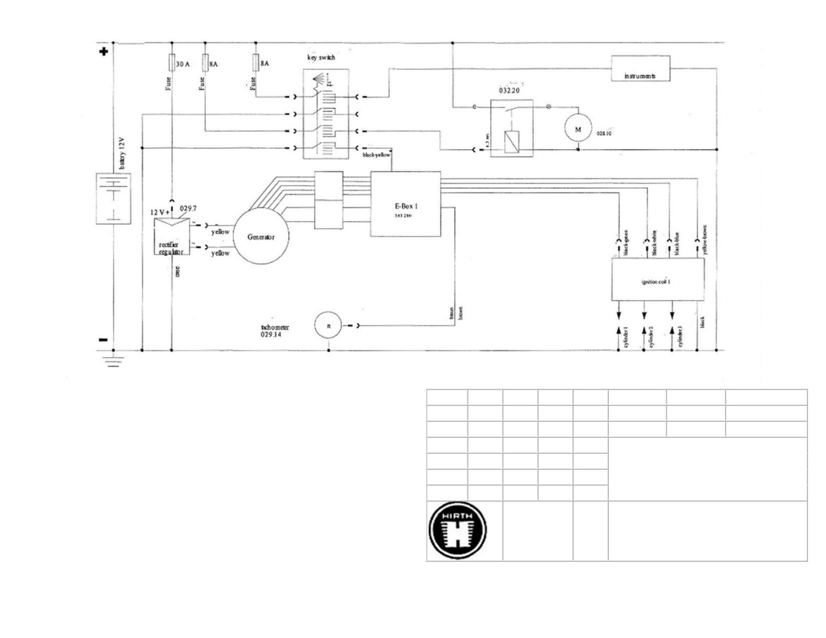
This wiring diagram is to be considered as a proposal for wiring
d
03.07.01
Rögele
General size of line wire: 1,5 mm2
c
Wiring diagram CDI - single ignition
b
PVL
Size of line from/to E-Starter: 16 mm2
a
3701
Tag
Name
Rectifier-regulator mount on cooling body (ca. 250x200x5mm)
-
-
Nr.
* Minimum distance to other current wires: 100 mm (4 in.)
16017 rev2
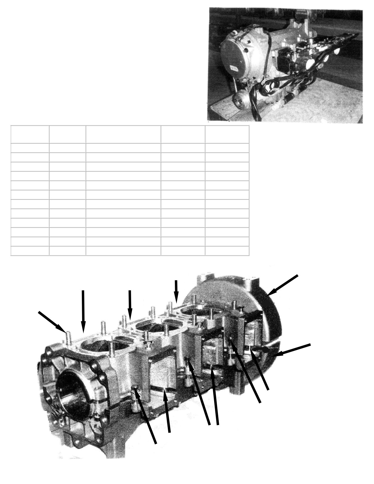
Spare part list
Engine
3701
100 HP
Fig. No.
Quantity.
Designation
Neoteric Part
No
10
1
Crankcase, complete
7160
Incl. 10a-10c
10a
1
Crankcase, downside
7161
10b
1
Crankcase, upside
7162
10c
12
Stud screw
7163
20
3
Hexagon head screw
6927
30
3
Sealing ring, aluminum
5629
40
8
Hexagon head screw
7165
50
8
Washer
7166
60
11
Serrated lock washer
6902
70
5
Cylinder screw
6901
80
2
Cylinder screw
2289
90
4
Cylinder screw
6911
70
70
70
10B
60
60
60
10C
10B
70
60
70
70
60
60
Form 16018 rev2
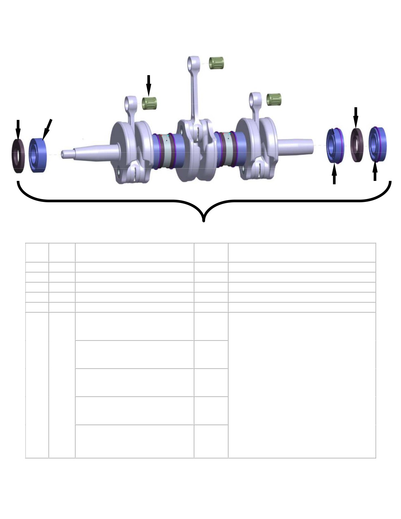
Crankshaft 3701
50*
30
30
25
40
20
10
Fig.
Qty.
Description
Neoteric
Remark / Notes
No.
Part #
10
1
Crankshaft
7167
Includes items 20 - 40
20
1
Deep grove ball bearing
7168
25
1
Deep grove ball bearing
7169
30
2
Shaft sealing ring
5453
40
1
Deep grove ball bearing
7170
* Connecting Rods are Color-Coded with a
Needle Bearing, Blue dot (#1)
7909
Paint Dot on the Piston end.
Engines built from 2010 onward also include
Needle Bearing, Yellow dot (#2)
6082
a Number Code next to the Paint Dot. The
coding corresponds to the correct Needle
bearing size. (Approx 0.0003" [0.008mm]
6083
50
3
graduation between each size)
Needle Bearing, Red dot (#3)
Blue (#1) is the smallest and Green (#5) is
the largest. Connecting rods with a Red (#3)
Needle Bearing, White dot (#4)
5464
dot are most common.
If the paint dot is missing and no number
Needle Bearing, Green dot (#5)
7910
code can be found, all bearings must be tried
for the best fit.
Form 17692 rev3
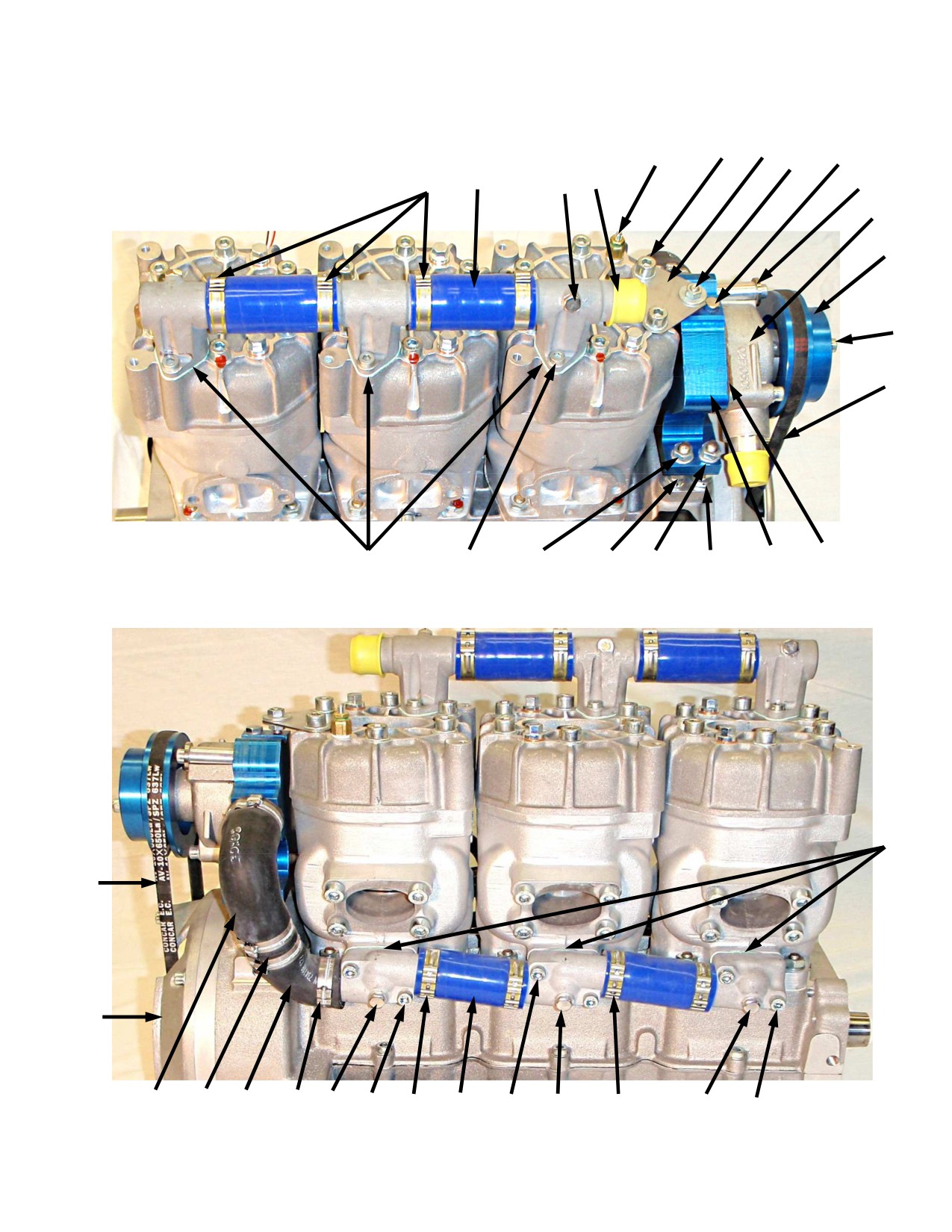
190
150
170
230
180
380
240
160
50
110
35
200
120
40
130
280
10
30
20
300
290
340
210
140
70
80
255
250
270
265
100
75
340
310
320
330
350
360
350
120
40
100
120
110
100
40
120
40
100
50
80
80
50
50
80
Form 17693 rev3

Cooling system 3701
Fig. No.
Quantity
Designation
Neoteric Part No
l0
2
Inlet intermediate piece
7171
20
2
Inlet end piece
7172
30
2
Inlet intermediate piece
7173
35
2
Plug
7174
40
6
Hexagon head screw
6927
Loctite 242
50
6
Sealing ring, aluminum
5629
65
6
Cylinder screw
2292
70
3
Sealing joint Gasket
6095
75
3
Sealing joint Gasket
6095
80
12
Cylinder screw
6911
Loctite 242
100
18
Locking washer
6902
110
4
Coolant hose
7176
120
12
Hose clamp
6802
1
Water pump and housing
7178
Contains Pos. 130-
240
130
1
Water pump
7179
140
l
Sealing joint f. water pump
7180
150
l
Holder for water pump
7181
clamping
160
1
Cylinder screw
7182
Loctite 242
170
1
Washer
6936
180
3
Cylinder screw
7183
Loctite 242
190
2
Washer
6916
200
1
Washer
5996
210
1
Casing for water pump
7184
230
1
Hexagon head screw
6927
Loctite 242
240
1
Sealing ring, aluminum
5629
250
4
Stay bolt
7185
Loctite 242
255
4
Hexagon head nut
7186
Loctite 242
265
8
Hexagon head nut
6233
270
12
Washer
6162
Loctite 242
280
1
Water Pump Pulley
6645
280
1
Water Pump Pulley SS
7613
290
3
Cylinder screw
7189
300
3
Washer
6916
310
1
Driver Pulley
6646
see forms: 17458rev2
310
1
Driver Pulley SS
7612
and 16673rev2 bellow
320
4
Cylinder screw
7189
330
4
Locking washer
6902
340
1
V-Belt
6104
350
2
Coolant hose 90°
7190
360
1
Connection tube
7191
380
1
Water Temp Sender
6277
Form 17694 rev4
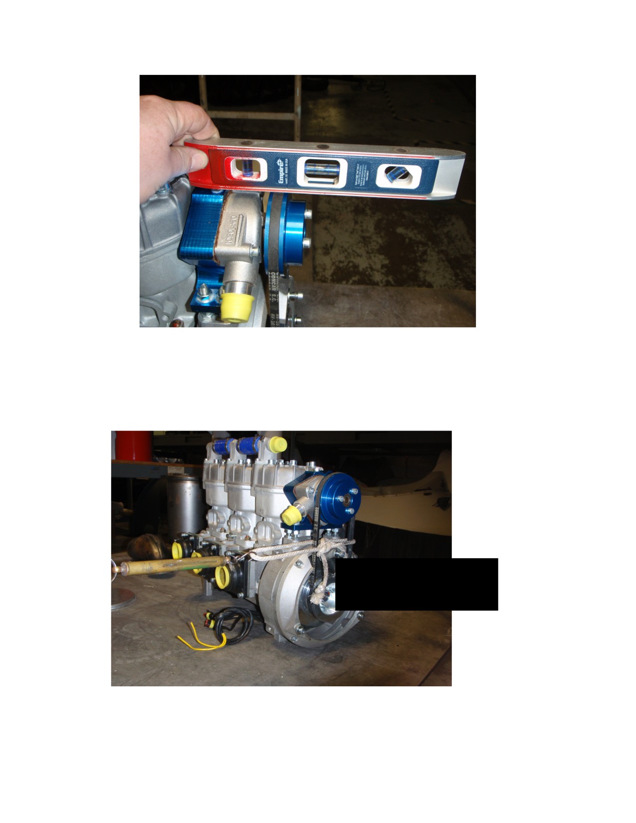
100HP Water Pump Belt Tension
1. Make sure Water Pump & Housing Assy is level.
2. Failure to do this will give an inaccurate tension reading and premature wear of #6104 Metric V-
Belt.
3. Attach a rope to Metric V-Belt in a loop.
4.
Attach other end to a pull scale.
#310 on form above
6646- Driver Pulley
7612 -Driver Pulley, SS
5. Pull 1.5 lbs on scale, Metric V-Belt should travel direction you are pulling 3 to 5 mm.
6. Find a point to measure from so your readings are accurate.
7. Continue to raise Water Pump & Housing Assy until tension is achieved.
Form: 17458rev2
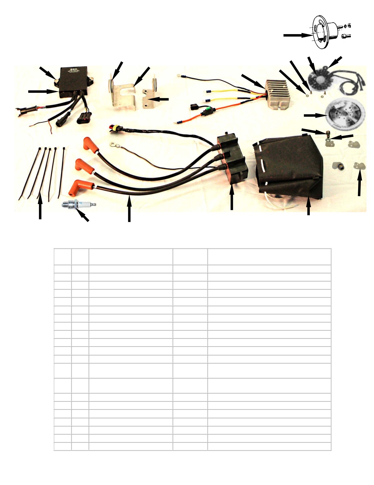
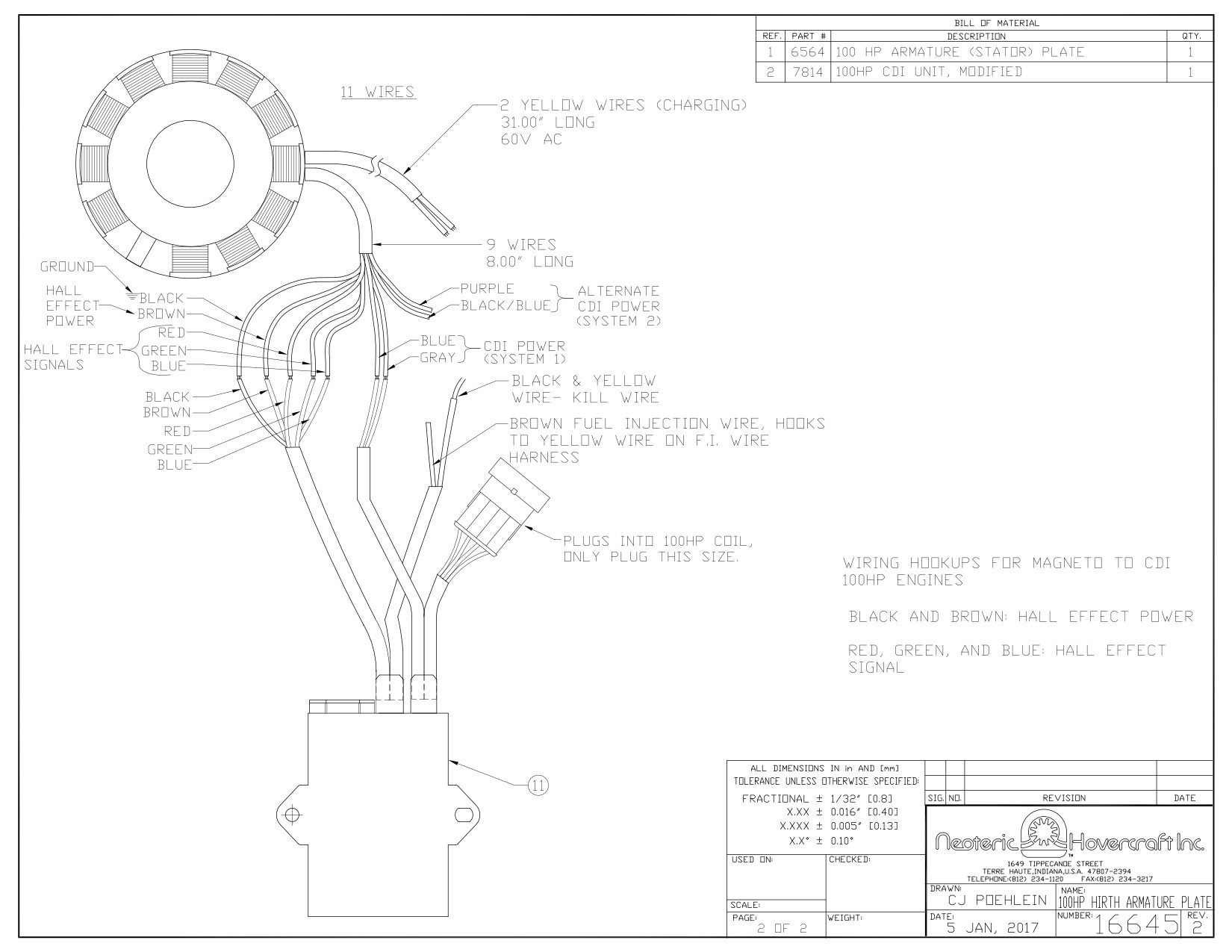
Hirth 100HP Ignition System
61
20
10
170
30
180
160
40
50
150
190
60
70
80
90
110
100
140
130
120
Fig.
Qty
Description
Neoteric
Remark /
No.
Part #
Notes
10
1
Grommet
7194
Not to Scale
20
1
Armature plate, complete
6564
Not to Scale
30
2
Cylinder screw
7182
Torque = 4 - 4.5 Nm (3 - 3.3 ft-lb) & Loctite 243
40
2
Washer
6936
50
1
Voltage Regulator
5338
60
1
Magnet flywheel, complete
7195
Not to Scale
61
1
Magnet support
5724
70
4
Cylinder Screw
6901
80
4
Lock Washer
6902
90
4
Plastic P-Clip
2192
100
1
Coil Bag
6705
110
1
100HP Ignition Coil
7053
Must be purchased as a set
120
1
Spark Plug Lead Set
7056
(contains black boots; not shown)
*No longer available; Must purchase set 7056
120
-
Spark Plug Lead, Old Style
7343*
(contains red boots as shown above)
130
3
Spark Plug
6187
140
1
Nylon Wire Tie
2372
150
1
100HP Modified CDI
7814
160
2
Hex Bolt
2230
170
2
Mount Plate Grommet
6806
No Longer Used
180
2
Outer Coil Mount Plate
5883
No Longer Used
190
3
Inner Coil Mount Plate
7197
No Longer Used
Form 17696 rev3
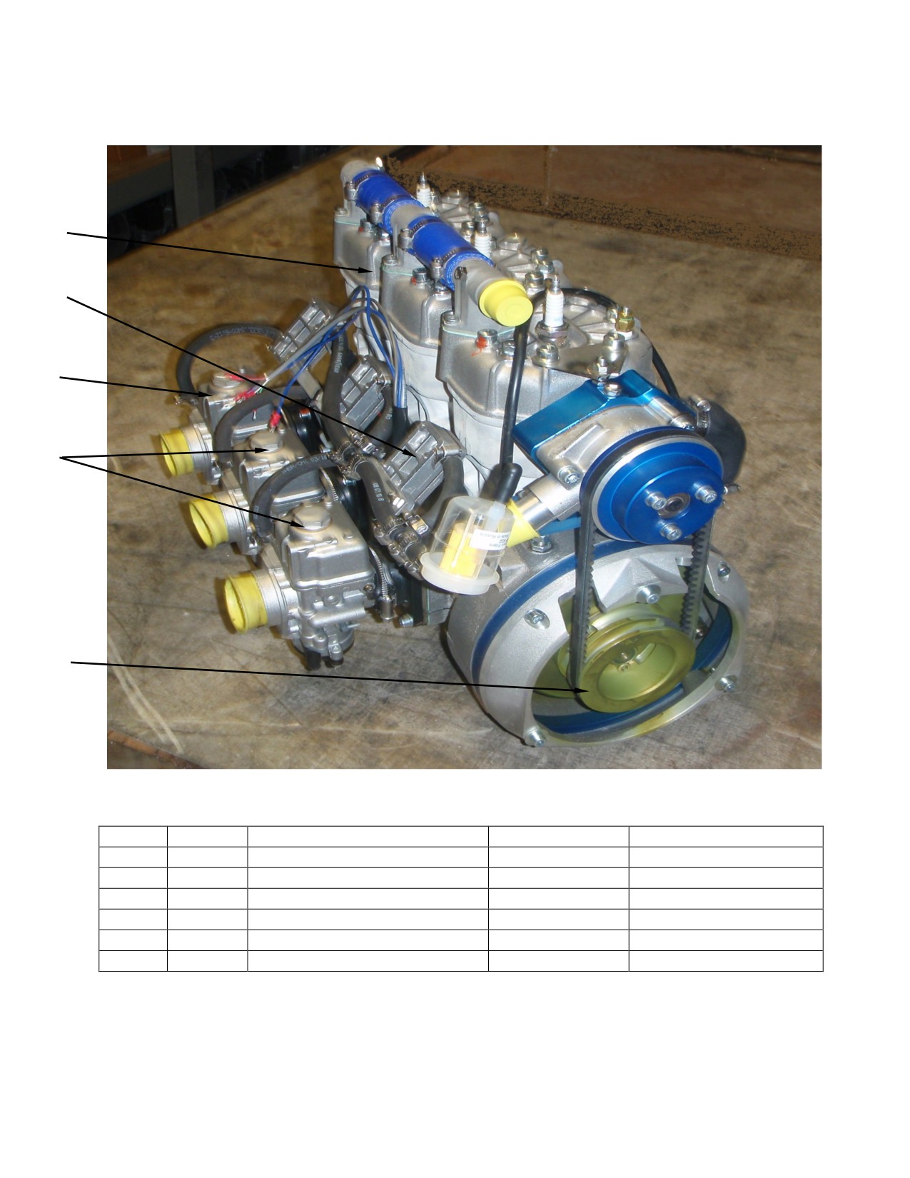
100HP Carbureted Engine
Offered Jan 2016
1
4
2
3
5
Fig No.
Quantity
Description
Neoteric Part No.
Notes
1
1
100HP Carbureted Engine
9219
Offered June 2016
2
1
Carburetor (left)
9266
3
2
Carburetor (right)
9267
Only for 100HP Carb.
4
1
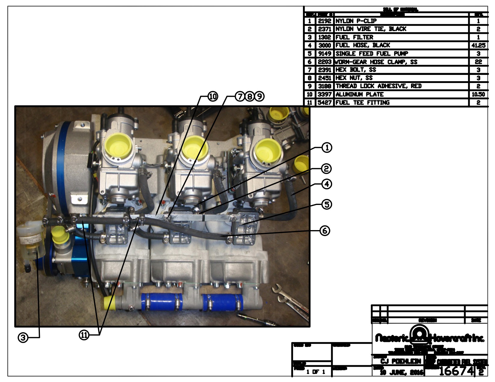
100HP Carb Fuel System
7211
Only for 100HP Carb.
5
Water Pump Driver Pulley
6646
5
Water Pump Driver Pulley, SS
7612
Form: 16673 rev2
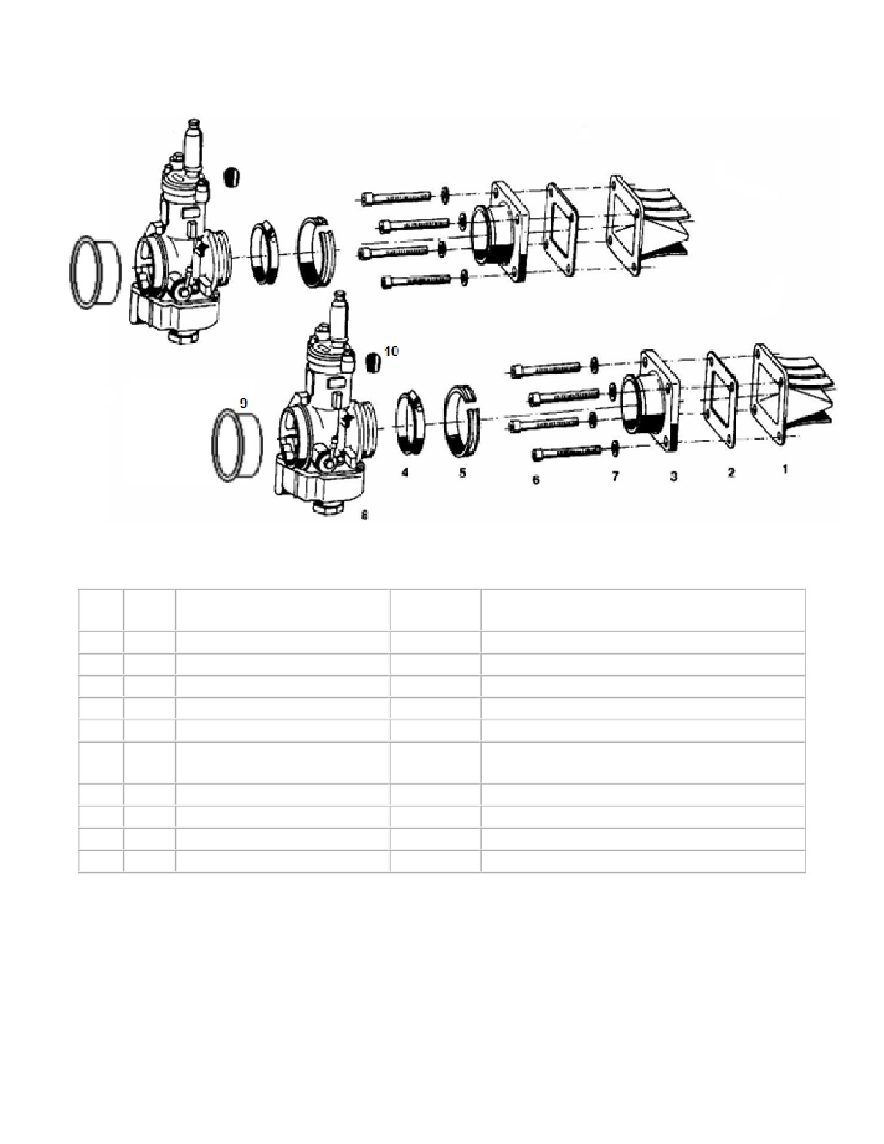
65HP Hirth Carburetor / Fuel mixture
(3203)
Fig
Neoteric
Qty.
Description
Remark/Note
No.
Part #
1
2
Reed valve
7203
2
2
Gasket
5463
3
2
Intake manifold/carb flange
6568
4
2
Hose clamp
9018
5
8
Rubber
9019
6
8
Cylinder screw
Torque = 9.6 - 11 Nm (7.1 - 8.1 ft-lb)
7183
Loctite 243
7
2
Washer
6916
8
2
Dellorto Carburetor
5355
See Form 17754 / 17755 for Carb Parts
9
2
Protective stopper
7207
10
Hirth Rubber Socket
7208
Form 17286 rev2
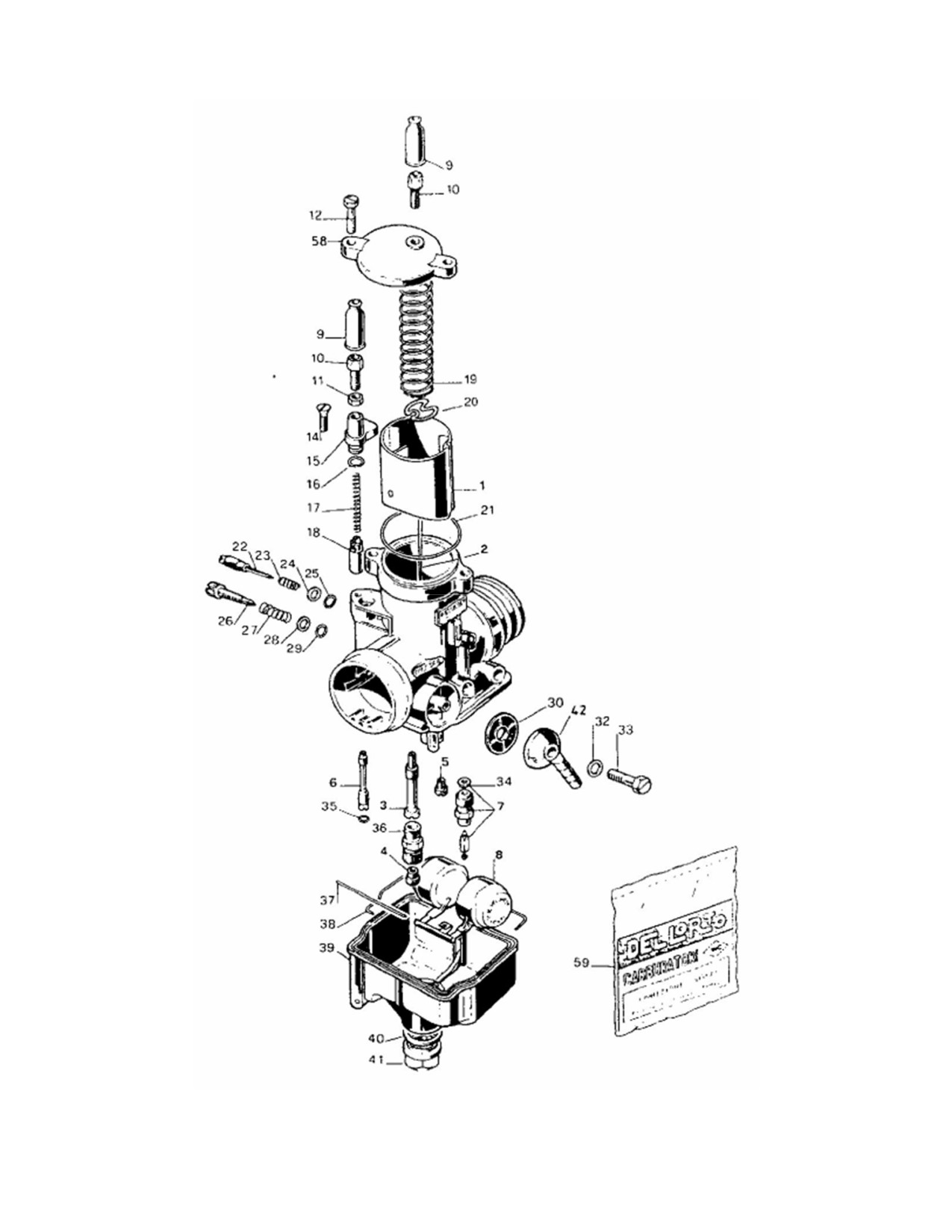
Carburetor (Dellorto) PHBE 34
Form 17754 rev2

Carburetor (Dellorto) F 33 A (PHBE 34 BD 6832)
Fig.
Neoteric
Qty.
Description
Remark/Note
No.
Part #
1
1
Throttle slide
9022
2
1
Jet needle, K36
6563
3
1
Needle jet
-
4
1
Main jet
-
See Form # 17367 for all Dellorto Jets
5
1
Idle jet, 65
9023
6
1
Cold start / Choke jet
7788
7
1
Float valve
9024
8
1
Float
6909
9
2
Rubber cap
6113
*Included in 7828 Kit
10
1
Choke Cable Adjustment
7828
*Must Purchase 7828 Kit
11
1
Choke Cable Adjustment Locknut
7828
*Must Purchase 7828 Kit
12
2
Top Cover Screw
9027
14
1
Choke Support Screw
9028
*Must Purchase 7828 Kit
15
1
Choke Support Casting
9029
*Must Purchase 7828 Kit
16
1
Choke Support O-ring
7828
Included in Pos. 59
17
1
Choke Valve Spring
9030
*Must Purchase 7828 Kit
18
1
Choke valve
7828
*Must Purchase 7828 Kit
19
1
Throttle Slide Spring
9025
20
1
Bracket plate
6973
21
1
Top Cover O-Ring
9026
Included in Pos. 59
22
1
Mixture Adjustment Screw
9031
23
1
Mixture Adjustment Spring
9032
24
1
Mixture Adjustment Washer
9033
25
1
Mixture Adjustment O-ring
-
Included in pos. 59
26
1
Idle Adjustment Screw
9034
27
1
Idle Adjustment Spring
9035
28
1
Idle Adjustment Washer
9036
29
1
Idle Adjustment O-ring
-
Included in Pos. 59
30
1
Fuel Inlet Filter
9037
32
1
Fuel Inlet O-ring
-
Included in Pos. 59
33
1
Fuel Inlet Screw
9038
34
1
Needle Valve Gasket Washer
-
Included in Pos. 59
35
1
Cold Start / Choke O-ring
-
Included in Pos. 59
36
1
Main jet holding screw
9039
37
1
Float Pivot Pin
9040
38
1
Sealing for float chamber
9296
Included in Pos. 59
39
1
Float Bowl
9041
40
1
Float Bowl Gasket Washer
7213
Included in Pos. 59
40
1
Float Bowl Gasket O-Ring
2739
Optional Replacement For Washer
41
1
Float Bowl Nut
9042
42
1
Fuel Inlet Nipple
6114
58
1
Carburetor Top Cover
9043
Includes Pos.
59
1
Gasket set
5468
16,21,25,29,32,34,35,38,40
Form 17755 rev4

65HP (PHBE) Dellorto Carb Jets
Parts List
Neoteric
Qty.
Description
Remark / Note
Part #
Main Jet, 155
5443
Main Jet, 142
5444
Main Jet, 145
5467
1
Main Jet, 160
5863
Main Jet, 150
9294
Main Jet, 158
6193
1
Idle Jet, 65
9023
1
Cold Start / Choke Jet, 90
7788
Atomizer / Needle Jet, AB/266
5726
1
Atomizer / Needle Jet, AB/262
5760
Atomizer / Needle Jet, AB/268
6194
1
Jet Needle, K36
6563
Form 17367 rev2
100HP Carbureted Engine Saltwater Package
Offered Jan 2016
1
2
3
Fig No.
Quantity
Description
Neoteric Part No.
Notes
HT6 Saltwater Air
1
1
6703
Intake Filter Box Assembly
100HP Coil & CDI Assembly
9157
2
1
100HP Carbureted Engine
3
1
9219
Offered June 2016
Modified
Form: 16675 rev2
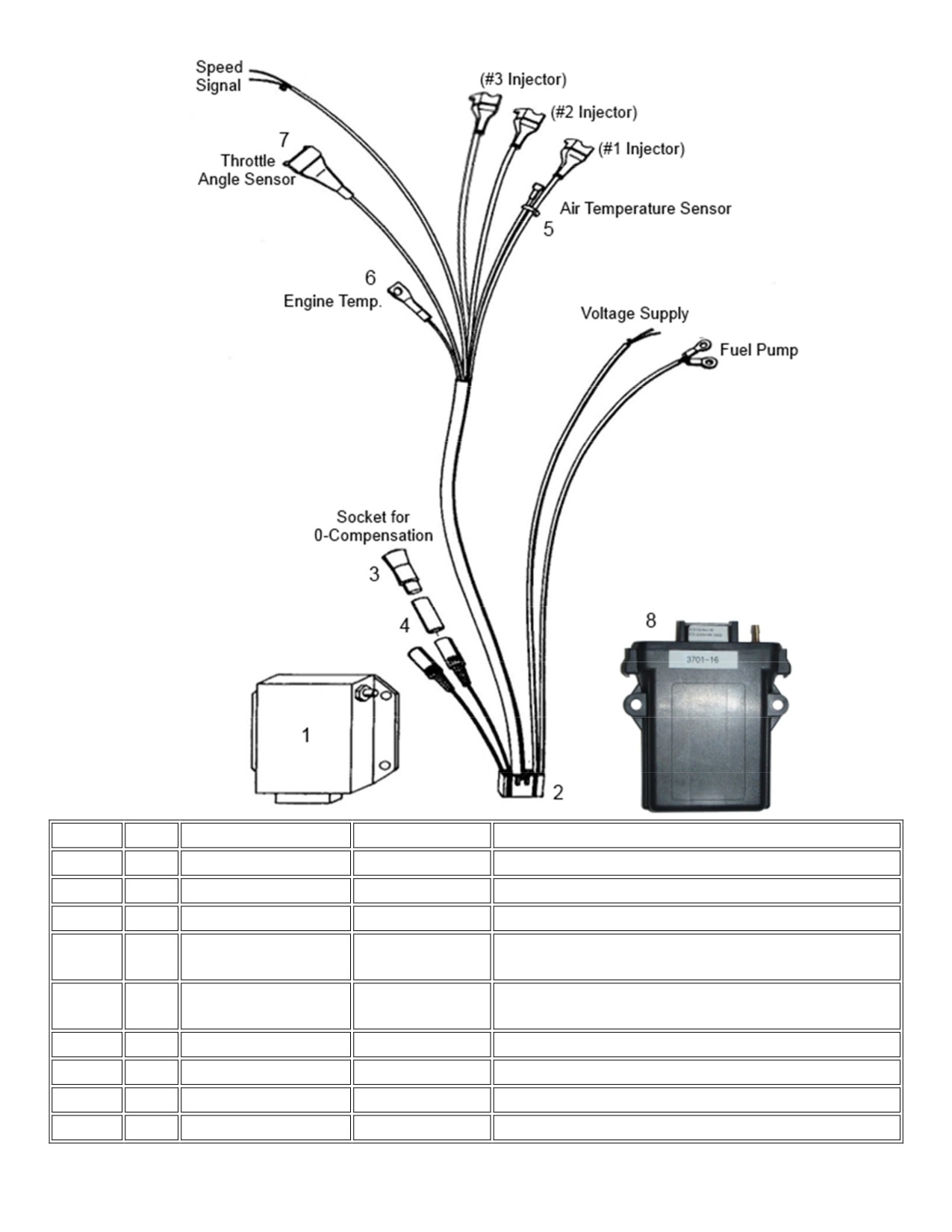
3-Cylinder Fuel Injection Electrical System
Fig.No.
Qty
Description
Neoteric Part #
Note
1
1
Red Computer Box
5616
Used on Early HoverTrek Models
2
1
Cable harness, Red
6453
Harness for Red Computer Box
2
1
Cable harness, Black
6210
Harness for Black Computer Box
3
1
0-compensation plug
7205
Used when optional manual enrichment device not
used -
4
1
Shrink tube
3192
Place on plug with 3 wires (cable colors red, blue,
black) 60 denotes length in mm
5
1
Air Temp Sensor
7525
6
1
Engine Temp Sensor
7526
Attached to Cylinder Head
7
1
Throttle Pos. Sensor
7567
8
1
Black Computer Box
6383
Used on Current HoverTrek Models
Form 17742 rev3
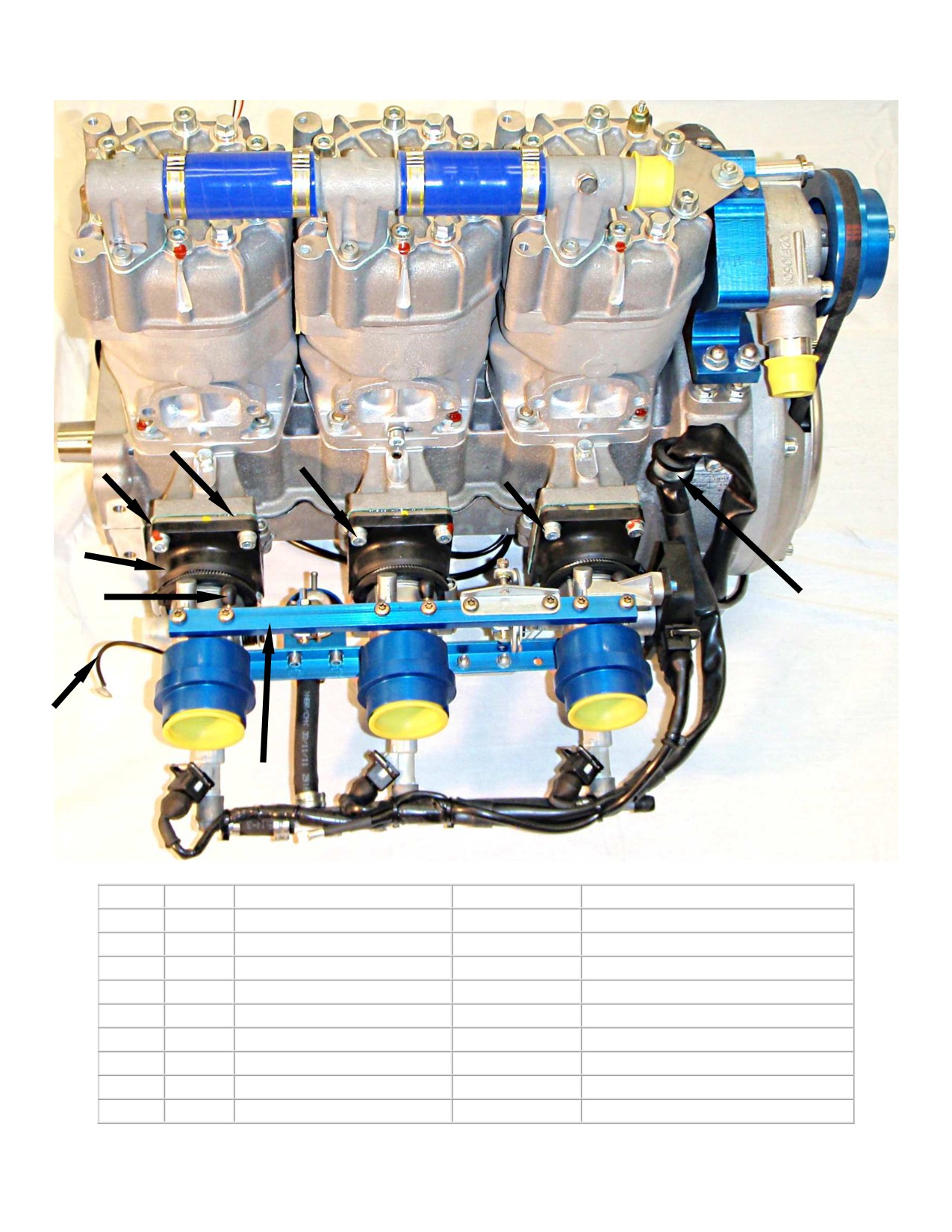
Fuel injection horizontal 3701
2
3
1
4
5
6
8
7
9
Fig. No.
Quantity
Description
Neoteric Part #
Remark note
1
3
Reed valve assembly
7203
2
3
Gasket
5463
3
12
Cylinder screw
2289
4
12
Washer
6916
5
3
Rubber carburetor flange
6568
6
3
Rubber socket
7208
7
1
Ground cable
6454
8
1
Cable clip
7206
9
1
Throttle manifold
6182
Form 17697 rev2
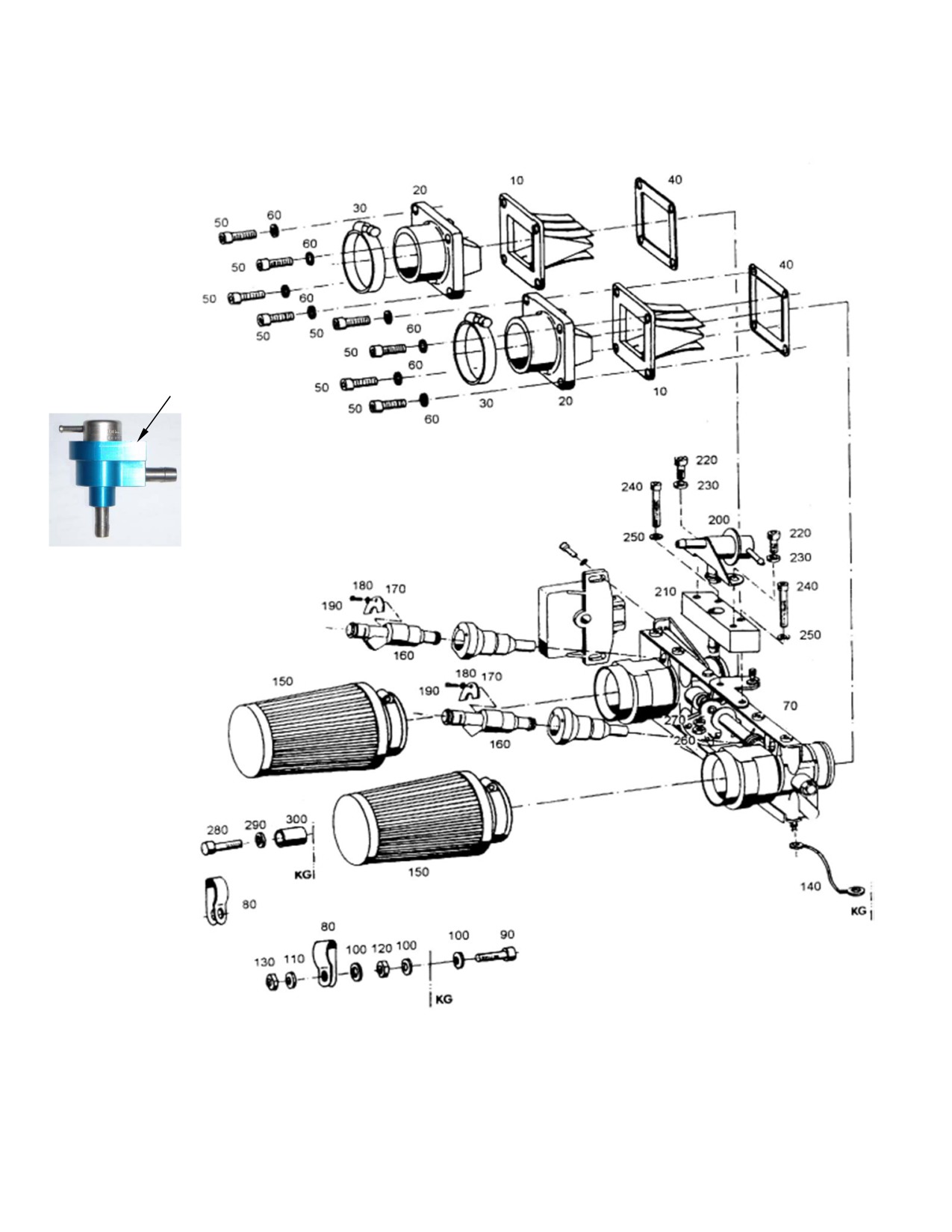
65HP Fuel Injection shown for simplicity
100HP Fuel Injection uses same part #'s
Fuel Injection /Fuel mixture 3203
200
Form 16021 rev3

Hirth 65HP Fuel Injection / Fuel mixture
Fig.
Neoteric
Qty.
Description
Remark / Notes
No.
Part #
10
2
Reed valve
7203
20
2
Intake manifold
6568
30
2
Hose clamp
9008
40
2
Gasket
5463
50
8
Cylinder screw
2292
Torque = 9.6 - 11 Nm (7.1 - 8.1 ft-lb)
60
8
Washer
6916
70
1
Throttle manifold
5594
80
2
Clamp
6929
90
1
Cylinder screw
6901
Torque = 9.6 - 11 Nm (7.1 - 8.1 ft-lb)
100
3
Washer
6916
110
1
Washer
5996
120
1
Hexagon head nut
9009
130
1
Hexagon head nut, self.
5572
140
1
Ground cable
6454
150
2
Air filter
6622
6904
*Used up to May-2011
160
2
Fuel Injector, Old Style
(Engine #902754 & Lower)
6903
Currently used, from May-2011 onward
160
-
Fuel Injector, New Style
(Engine #902754 & Higher)
170
2
Injector Holding plate
9010
180
2
Washer
9011
190
2
Cylinder screw
9012
Loctite 243
7188
Shown in illustration;
200
-
Pressure regulator, Old Style
*Used up to May-2011
(Engine #902754 & Lower)
7932
200
1
Pressure regulator, New Style
Currently used, from May-2011 onward
(Engine #902754 & Higher)
200
-
Pressure regulator, Replacement
7279
Compatible with both old & new styles
210
1
Pressure regulator holder, complete
9013
220
2
Cylinder screw
7189
Torque = 9.6 - 11 Nm (7.1 - 8.1 ft-lb)
230
2
Washer
6916
240
2
Cylinder screw
9014
Loctite 243
250
2
Washer
6936
260
2
Hexagon head nut
9015
270
2
Washer
9016
280
1
Cylinder screw
9017
290
1
Washer
6936
300
1
Bushing
6935
Form 16022 rev3
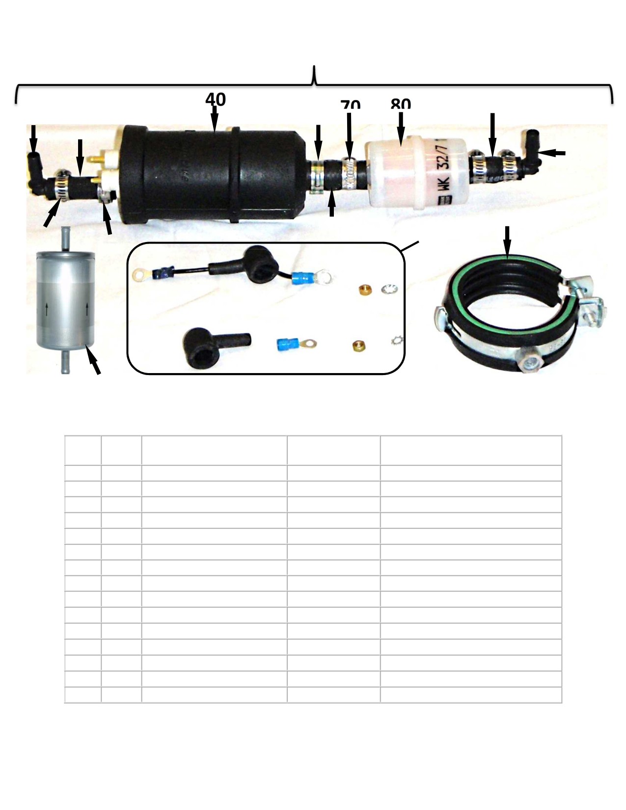
Hirth Fuel System
130
90
150
50
10
100
110
60
20
30
120
140
Fig.
Qty.
Description
Neoteric
Remark /
No.
Part #
Notes
10
1
Fuel Line
6335
20
3
Screw/Band Hose Clamp
2203
30
1
Pinch Hose Clamp, Sm
5993
40
1
Electric Fuel Pump
6414
50
1
Pinch Hose Clamp, Lg
5986
60
1
Fuel Line
6334
70
1
Gapless Hose Clamp
6943
80
1
Fuel Filter
5372
90
3”
Fuel Line
3193
100
1
Large Elbow
2674
110
1
Fuel Pump Holder
6336
120
1
Fuel Pump Connection Kit
6628
130
-
Fuel Pump Assy
6666
Includes Fig No. 10 - 120
140
1
Micro Fuel Filter
5373
150
1
Small Elbow
2438
Form 17698 rev2
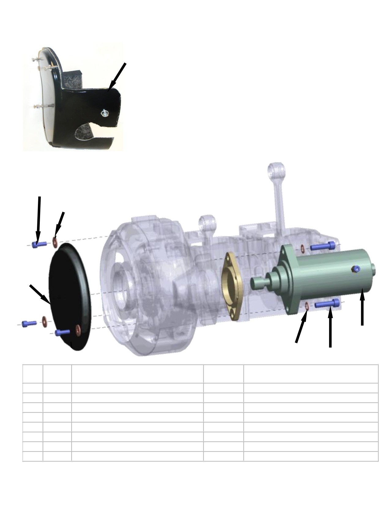
Starter / Flywheel Cover
35
10
20
30
60
40
50
Fig.
Qty.
Description
Neoteric
Remark / Notes
No.
Part #
10
3
Cylinder Screw
9074
20
3
Flat Washer
5996
30
1
Flywheel Housing Cover Plate
9075
35
1
Fiberglass Water Pump Cover
9073
Replaced housing cover plate, 2015
40
2
Serrated Lock Washer
5995
50
2
Cylinder Screw
2348
60
1
Electric Starter (OEM) (old use 9309)
6982
Shown Above
60
-
Electric Starter (Replacement)
9309
Not Shown
Form 17699 rev4
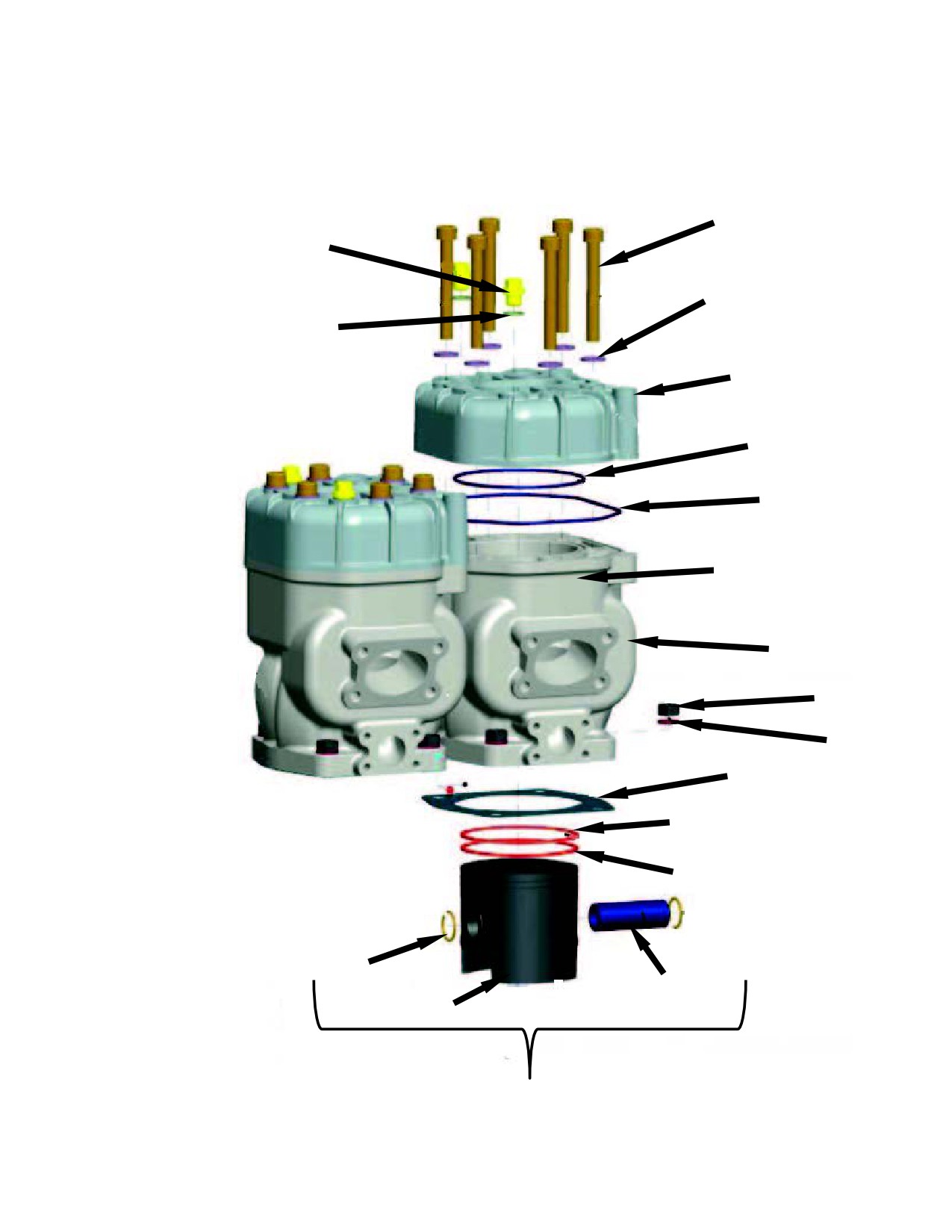
Hirth 100HP Cylinder Parts Drawing
90
110
100
120
60
70
80
Letter
Note: 3rd Cylinder
B
Designation
Not Shown in
Drawing
10
Cyl. Marked with
Letters A, B, or C.
30
Piston Marked with
corresponding Letter.
40
Note proper Cyl. Letter
20
when ordering.
52
53
55
54
51
50
Form 17759 rev2

Hirth 100HP Cylinder Parts List
Fig.
Qty
Description
Neoteric Part #
Remark note
No.
Cylinders Marked w/ Letter A, B, or C. If
no Letter it is a B cyl. Ensure to check
10
3
Cylinder
6090
cylinder & order proper replacement. Cyl
marked toward top, Letter is by itself.
20
3
Cylinder base gasket
5455
30
12
Hexagon head nut
6233
40
12
Washer
6234
50
3
Piston set
5450
Contains Fig. 51-55
51
1
Piston
7210
Piston Marke w/ Letter corresponding to
cylinder. A, B, or C. Marked on top of
piston.
52
1
Piston ring
5452
53
1
Piston ring
5451
54
1
Piston pin
5972
55
2
Circle clip
6301
60
3
Cylinder head
6089
Specify Single Ignition
70
3
O-Ring
5892
80
3
O-Ring
5893
90
18
Cylinder screw
6408
100
18
Washer
6407
110
6
Bleed screw
6409
120
6
Sealing ring
6410
Form 16622 rev2
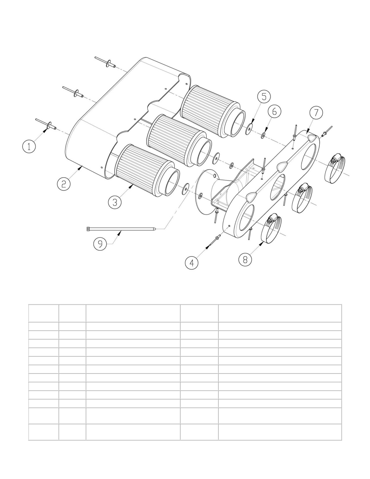
Hirth HT6 Air Box Assembly
Fig. No.
Qty
Designation
Neoteric
Remark
Part #
1
3
Rivet
2156
2
1
Fiberglass Air Box
5652
3
3
Air Filter
6622
Includes item 4
4
10
Rivet
2058
5
3
Large Washer
2516
6
3
Small Washer
2352
7
1
Air Collector
6913
8
3
Hose Clamp
2201
9
3
Wire Tie
2371
-
-
Polyurethane Sealant
2378
Not Shown
-
-
Sealed Air Box Assembly
6703
Includes item 1 - 9 as shown above
*Entered Service in Late 2010 - Current
-
Unsealed Air Box (Old Style)
5653
Includes item 1, 2, 3, 4, 6, 7
*Used on Craft Produce Before Late 2010
Form 16621 rev3
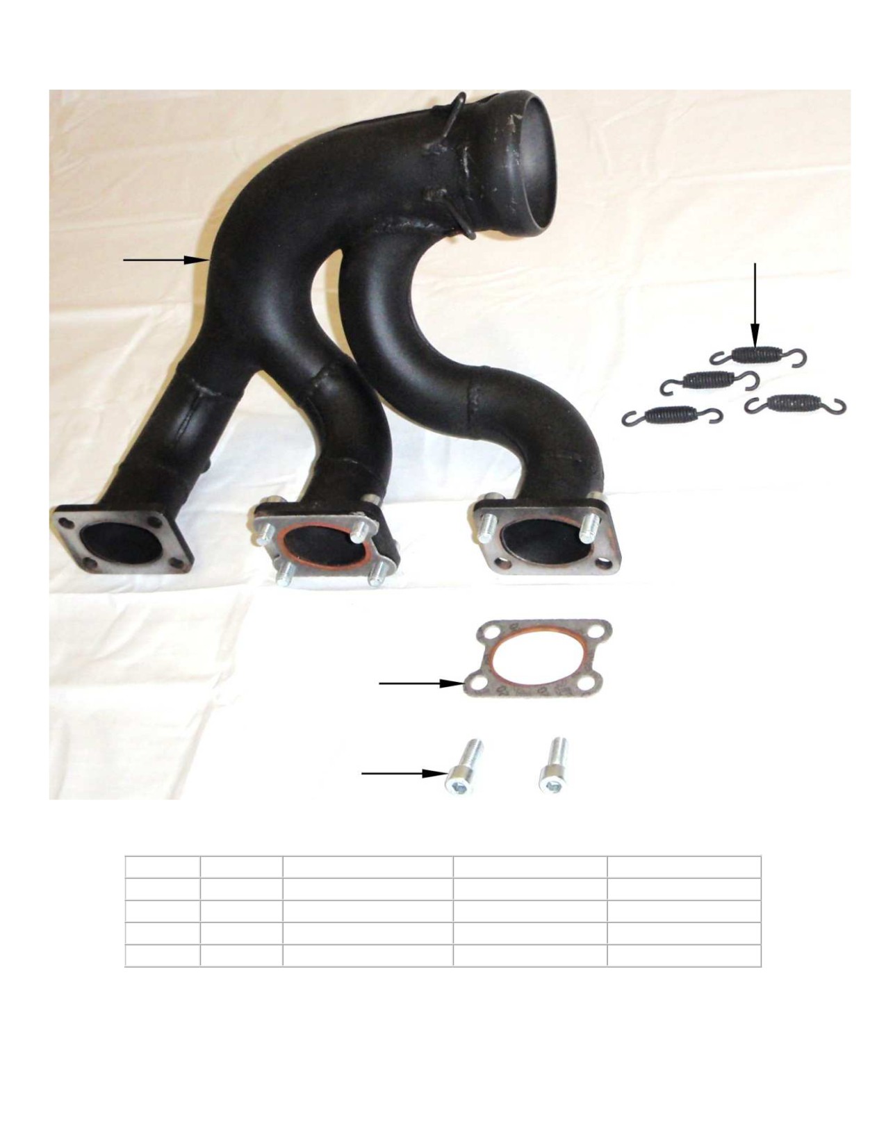
Hirth 100HP Exhaust Header Parts
40
10
20
30
Fig. No.
Qty.
Designation
Neoteric Part No.
Remark note
10
1
Outlet Manifold
5601
20
3
Outlet gasket
5914
30
12
Cylinder Screw
6932
40
4
Exhaust Spring
5421
Form 17760 rev2
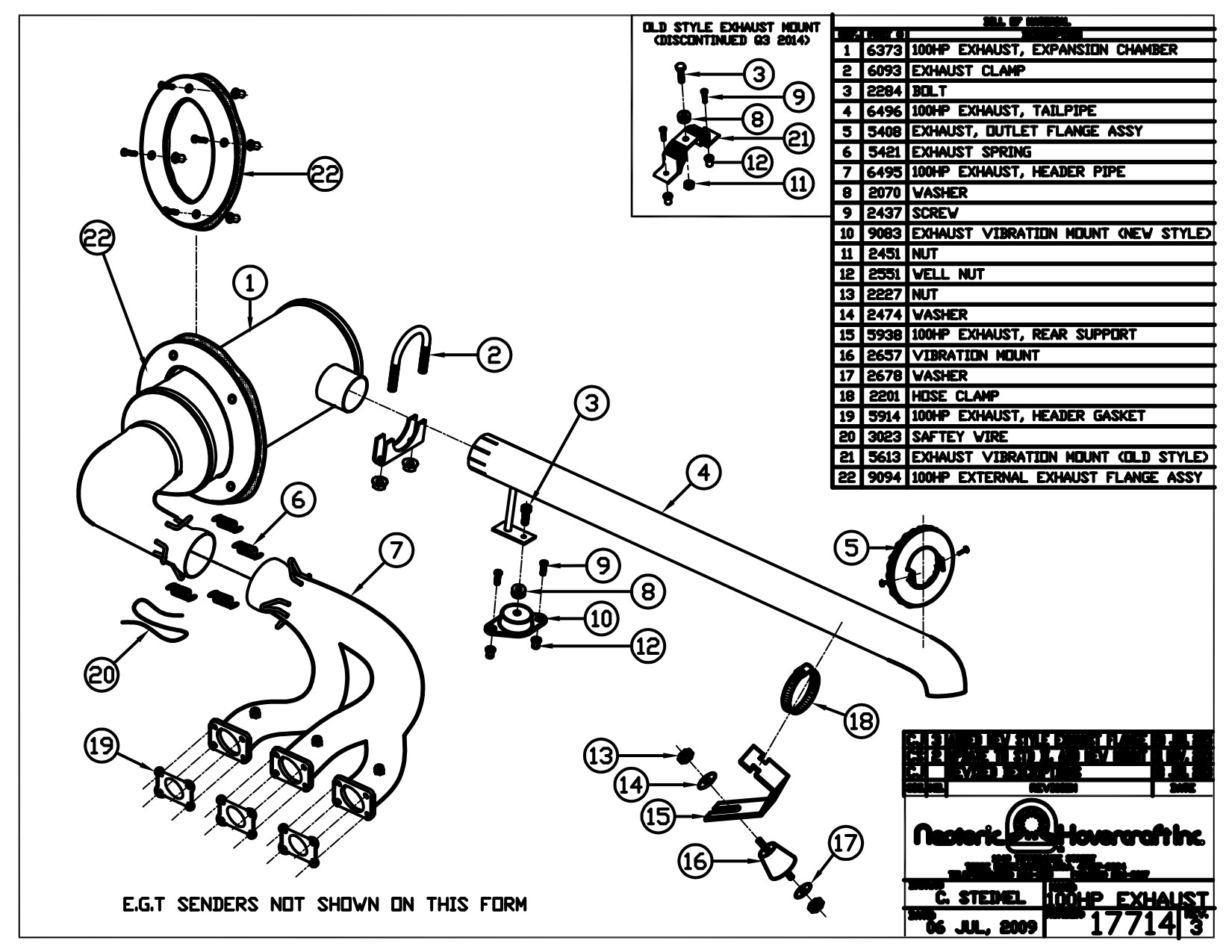
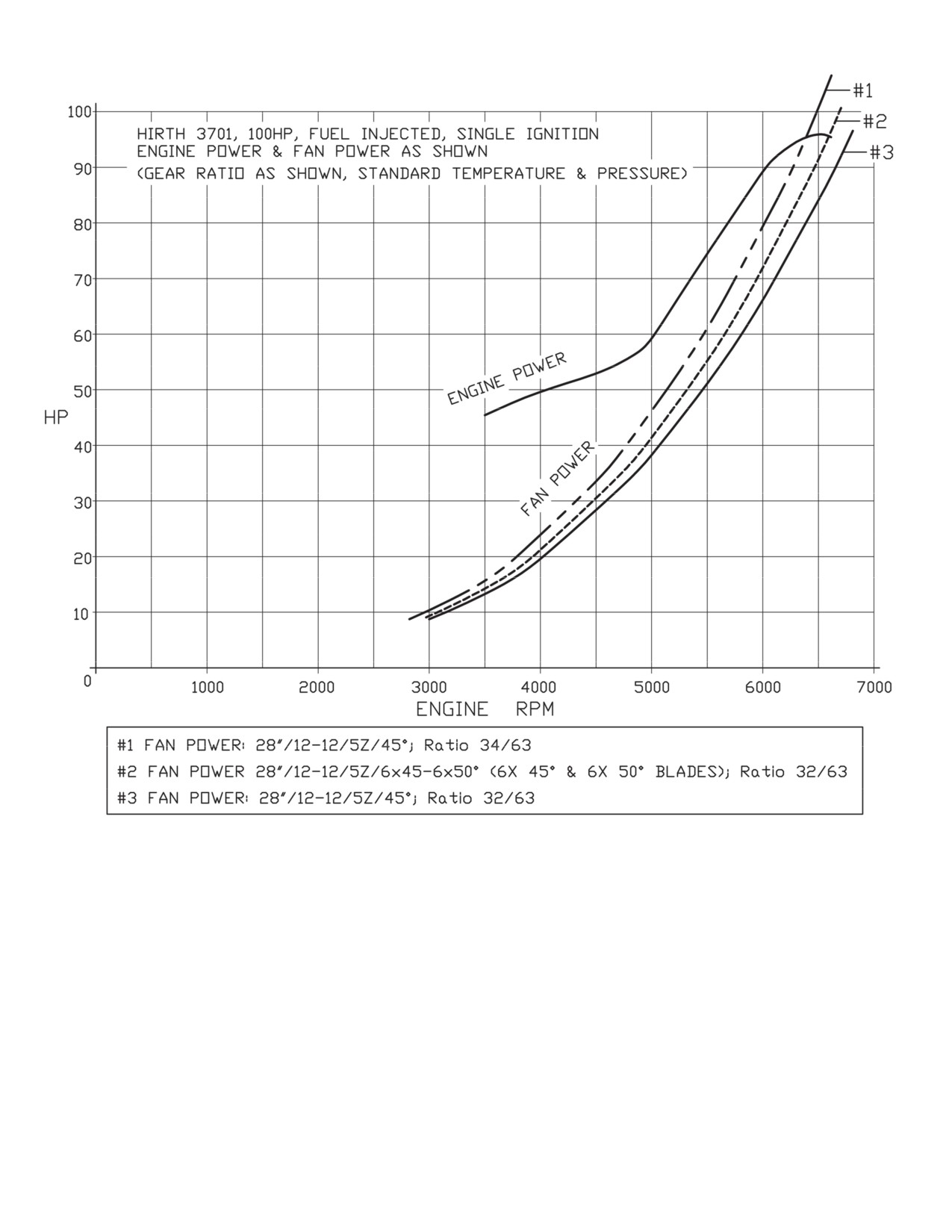
Form 17761 rev2
Form 17762 rev2

Neoteric
Hovercraft Inc.
1649 Tippecanoe Street • Terre Haute, Indiana, USA 47807-2394
TELEPHONE: 812-234-1120 • 800-285-3761 • FAX: 877-640-8507
EMAIL: Hovermail@NeotericHovercraft.com • WEB: NeotericHovercraft.com • RescueHovercraft.com
Engine Troubleshooting & Maintenance
1
Engine problems
When an engine will not start, first check for spark. Pull the spark plug and connect it to the high
tension lead. Place the plug on the engine block and crank or pull the recoil starter and look for
spark. Sometimes in sunlight it is impossible to see the spark. It might be possible to hear the
spark and, lastly, if you get an electrical jolt then this confirms spark is present.
While the plug is removed, place a finger over the plug hole and crank the engine. Check for
compression. Lastly, check for fuel. Remove the air cleaner, open the throttle and squirt gas into
the cylinder. If the engine fires then stops, or runs only for a short time (1-2 seconds), this
indicates that the engine is not getting fuel. Check the tank level, primer, filter, fuel line and
quick connects, if installed. To pinpoint the problem, rig up a separate fuel supply directly to the
carburetor. If the engine runs properly, disconnect the temporary fuel supply and move along the
fuel line, changing components until the culprit is found.
The three fundamentals to check are spark, compression and fuel. Engines will not function if
any of these are missing. Always check the easiest things first. When there is no spark, check the
kill switch. Next, begin replacing components, coil, cdi and finally, remove the flywheel and
check the magneto.
Normal compression should be between 100 and 120 p.s.i. If compression is low, the engine will
be difficult to start. If no compression, the engine will have to be dismantled and repaired.
The fundamental rules for the mechanic are 1) Always check simple things first, and 2) Check
one thing at a time.
Engine adjustment
Modern materials limit the maximum power any engine can generate. Running an engine at the
maximum temperature, just below the melting point of its constituent materials, will produce the
maximum power. It’s in our interest to tune the engine so that full power is developed, yet the
engine does not melt.
Think of an engine as an oxyacetylene cutting torch. When more fuel (acetylene) is added, the
flame temperature drops but when more oxygen is added the temperature goes up. It’s exactly
the same with an engine.
Form: 17477
2
Oxygen varies depending on air temp and pressure. High altitude means low air pressure. Hot
weather means low oxygen. With varying oxygen, the fuel also must be adjusted or the engine
can melt. Fuel supply is regulated either by injectors, which are computer controlled, or by a
carburetor. When an engine runs with too much fuel it is said to be running rich. When there is
too little it is running lean. Of the two, running lean is the most dangerous. The engine will
develop more power but will be close to melting. Rich and lean have nothing to do with the
quantity of lubricating oil. Engines must have lubricating oil or they will seize. See Engine
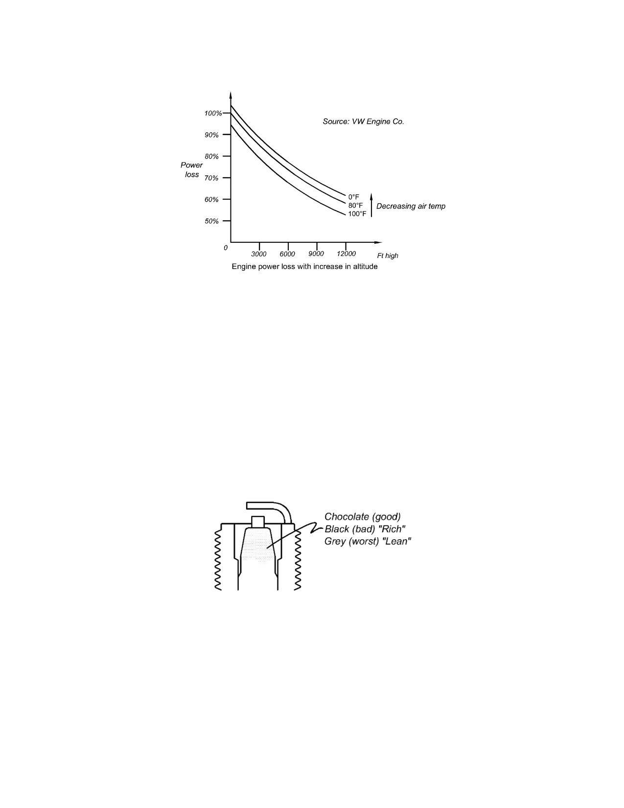
Altitude and Air Temperature graphs in the engine Appendices at the back of this manual.
To check how an engine is running, look at the spark plug after the first half hour of operation.
The plug color must be chocolate. If black, this indicates the engine is running rich; the black is
unburned hydrocarbon. If grey, this is dangerous; it means the engine is about to melt. The grey
is ash from the oil/fuel and particles of aluminum off the piston which are depositing on the plug.
The engine is running lean.
In cold weather, i.e. below freezing or whenever engine icing occurs, the engine heat flap can be
untied and attached to the underside of the air filter box where Velcro strips are provided. This
directs heated air from the engine cylinders into the intake filters, which will correct the tendency
for engine icing to develop. This is only available on Fuji engine equipped Neoteric craft.
The Hirth engine produces hot air from its air cooling system, part of which flows over the
carburetors; this air is sufficient to prevent carburetor icing.
Form: 17477

3
Cautions
When replacing spark plugs, be sure that the plug is tight, but not too tight; it should be about 15
to 18 ft lbs. Coat threads with copper based anti-seize thread lubricant (Anti-Seize compound
sealing lubricant 765-1363 is suitable). A loose plug can lead to the cylinder head melting.
When mixing fuel for the engine, use proper 2-cycle oil, and use a good quality oil with a
reputable brand name; snowmobile oil is preferred; use NAMMA TC- W3. Do not use synthetic
oil. Mix 40:1, i.e. 16 oz of 2-cycle oil to 5 gallons (25ml oil to 1000 ml (1 liter) gas). Too much
oil can cause carbon buildup inside the cylinder head, piston walls, the rings and their grooves;
this can result in ring sticking followed by a subsequent loss of compression. The engine will
then become difficult to start and to keep running. It is advised to use high octane gasoline when
available; this lessens the possibility of pinging and pre- detonation.
Engine maintenance
1.
Always mix gasoline and oil unless the engine is equipped with an oil injection system.
For oil injection engines, add oil 100:1 to gasoline until the oil delivery system can be
monitored for proper performance.
2.
For the first 10 hours of new engine operation, restrict maximum power to the minimum
possible amount, no more than 10-15 seconds of full power bursts from time to time, and
try to run the engine for longer periods, such as ½ hour at 4000 rpm, then 3000 and 5000,
all for ½ hour intervals.
3.
Mix gasoline (high octane is recommended) with North American Marine Manufacturers
Association Standard TCW3 2 cycle oil 40:1 and mark the portable fuel tank 40:1 with a
removable sign to prevent accident addition of gas without oil.
4.
Engine idle should never exceed 1400 rpm. For 100 hp engines, minimum cranking speed
is 500 rpm.
5.
Exhaust gas temperature should not exceed 1350° F, while cylinder head temperature
should remain below 535° F unless it is a liquid cooled engine, which runs at max 240° F,
min 160°F.
6.
Do not over rev an engine; 6500 is tops.
7.
The Hirth engine company recommends torqueing the cylinder and head bolts after the
first 10 hours, but this is immensely difficult. Where possible, these are checked by
Neoteric before engines are installed.
8.
When the hovercraft has arrived at its place of use, check spark plug color after the first
½ hour test run. Make fuel mixture adjustments as required. Get the help of a snowmobile
or motor bike mechanic to help if you are unsure of this task.
9.
Always examine an engine for oil leaks and investigate such leaks whenever they are
found.
10. Always wash the engine with fresh water after operating, then spray down with kerosene,
WD40 or light machine oil. This will prevent corrosion and is especially important for
salt water operation.
11. Whenever operating in a dusty region, remove engine air filters and clean in accordance
with instructions found elsewhere in the manual.
12. Always inspect engine for cracks, loose bolts or fittings and check all belts for proper
tension. Correct when needed.
Form: 17477

4
13. Do not crank engine excessively. If it does not fire within 5-10 seconds, something is
wrong. Check that the kill switch is engaged. Remove plugs and clean excessive oil.
Replace plugs and restart.
14. Injectors can be used to prime the cylinder. Open throttle ¾ of a turn and you will hear
the injectors buzz.
15. Always inspect cooling systems and radiators; clear debris and make sure coolant level is
sufficient. Also check pump belt.
16. Ensure there are no loose wires, especially battery terminals and engine ground wire.
17. When checking the engine for problems, endeavor to make one change at a time then
check before making any additional changes.
18. To test fuel injected engines, a laptop program must be obtained from Hirth. The
computer chip can be changed with different mapping.
19. Engine shut down temperature for air cooled engines should be under 300° F. cylinder
head temp.
20. Always turn injected engines on and off using the fuel pump switch. Turn key on, then
turn fuel pump switch to on and listen for fuel pump. Use the key to start the engine. To
stop the engine, turn the fuel pump off first in order to depressurize the fuel system and
stop the engine. Then turn the key off. The fuel pump can take up to 5 seconds to prime.
Most hovercraft are equipped with some form of primer bulb needed to re-prime the fuel
pump whenever fuel line air blockage occurs.
Form: 17477

Craft Service & Maintenance
5
Neoteric Hovertrek™ lubrication
Fan shaft bearings:
After every 25 hours, lubricate each fan shaft bearing with regular wheel bearing grease. Do not
overgrease and damage bearing seals.
Control bearings:
Using SAE 30 oil, lubricate all rudder blade bearings, clevises, pins and rudder push pull cable.
Torsion steering post:
Lubricate reverse thrust cable drums, BMW reverse thrust levers and cables, throttle cables, seat
sliding and rolling parts on SxS craft with SAE 30 oil.
Engine:
Choose an oil with a National Marine Manufacturers Association (NMMA) TC-W3 or similar
standard 2 cycle engine oil and mix 40:1 with 95 octane gasoline.
40 Gas
:1 Oil
1 US gallon
(=3785 ml):
0.025 US gallon (=95ml)
8 US pints
(=1 US gal):
0.2 US pints
128 fluid oz
(=1 US gal):
3.2 fluid oz
Trailer:
Check and repack wheel bearings after 1000 miles. Lubricate winch with SAE 30 oil. Lubricate
ball hitch with SAE 30 oil.
Form: 17477

6
Neoteric Hovertrek™ electrical fuses
Reverse thrust system :
could be round tube fuse or blade fuse 15 amp
Reverse thrust computer:
round tube fuses or blade 5 amp/computer (watertight holder;
only models prior to 2008), new digital computer
Navigation lights, headlights, instrument lights:
20 amp blade f u s e ( f o r C o n v e n t i o n a l R e s i s t a n c e
Light) 10 amp for current LED light.
Bilge pump and horn:
10 amp
Siren:
Current model: 20 amp blade built inside at back (Prior to
2006: outside at back.
Strobe or rotating light bar:
10 amp
Gauges:
10 amp
GPS:
Self-equipped fuse
Searchlight:
15 amp
Cigarette lighter plug and deck plug:
10 amp
Volt regulator:
30 amp
Side lights:
15 amp
Injected engine computer:
15 amp
Marine radio:
250 volt/6 amp
Skirt repairs
Replace segments when worn or damaged. Operating your Neoteric Hovertrek™ with holes and
tears in the skirt can be dangerous and is not recommended. If skirt damage is extensive, replace
the entire skirt. With care and good operating procedures a skirt should last for 120 hours. Even
under normal conditions, skirts take a great deal of punishment and might wear badly in as little
as 25 hours. Damage is usually erosion, which is confined to the lower edges of the skirt. Wear
patches can be inexpensively stitched over the worn area; use 16 oz. Neoprene Coated Nylon
truck tarpaulin material, but any fabric material at hand will work, such as 7oz/sq yd nylon pack
cloth. When one or more segments are torn, be sure to make speedy replacement since each
damaged segment lowers the hoverheight slightly. This then increases the surface contact of all
the skirts so that they will all wear more rapidly.
Major fan and transmission repairs
A.
Remove fan intake screen.
B.
Disconnect fuel supply.
C.
Remove all electrical connections, mark each wire with a number and take note
of connection. Wires will have to be cut. Mark all cut wires for identification
during reassembly.
D.
Remove choke and throttle cables.
E.
Undo bolts holding engine mount feet to vibration mounts. Collect spacers and
label their location.
F.
Remove thrust duct using a screwdriver. Remove or loosen set screw above fan
hub key. This might be a square head set screw which is easy to remove. If it is
Form: 17477

7
an Allen head set screw this is more difficult to loosen. Apply heat with a
propane torch to the fan taper lock and concentrate around the set screw area as
that will soften the Loctite.
G.
Remove the three 5/16 hex head bolts holding the taper lock bushing. Place two
of these bolts in the threaded holes in the taper lock flange and tighten until the
taper lock bushing separates. A wheel puller is needed to remove the taper lock
off the fan shaft. Then the fan will come off.
H.
To remove the fan shaft: clean off any paint or corrosion on the fan
shaft. Loosen the bearing clamps and tap the shaft through the bearings while
spraying the shaft with WD40. Use a soft Aluminum or copper drift to force the
shaft out through the bearings. Remove the large drive sprocket by loosening the
small Socket Head screws on the B Lock assembly holding the sprocket to the
shaft. Remove the belt. Remove the 3 Hex head bolts holding the Belt Sheave
and loosen all engine mount bolts. Remove the bolt shims between the engine
and the engine mount in order to loosen the belt. Start with the shims under the
engine bolts closest to the front of the craft. Make sure to keep the shims together
and when reassembling, the exact same shims must go back under the exact same
engine bolt.
I.
Return the shaft and the complete fan to Neoteric with the taper lock for
balancing the assembly after repairing.
J.
Remove the foam vibration isolation strip; it might have to be cut off.
K.
Undo the eight 7/16 hex stainless steel bolts holding the thrust shroud. Force
the shroud back.
L.
Tilt machinery module forward and remove from craft.
M.
In operation, check belt adjustment; belt should run very slightly to the front of
the craft. This is achieved with slightly thicker shims under the engine mounts
toward the rear of the craft.
N.
Fan blades can be replaced through the opening created by removing the thrust
duct. Work on fan blades is more easily achieved by removing the fan to the
workbench. Take fan taper lock bolts out and screw them into threaded holes
on taper lock. Tighten until taper is broken and fan is removed using a wheel
puller and heat.
O.
To remove engine drive sprocket, undo sheave bolts, remove belt sheave
flange, fit puller and tension, then heat evenly using propane or oxy-acetylene
flame until sprocket breaks loose.
P.
Re-assembly:
Torque fan taper lock to 12 ft lb.
Torque sprocket locking hub to 7.5 ft lb.
Torque engine bolts to 55 ft lb.
Torque drive sprocket to 65 ft lb.
Torque bearing bolts to 65 ft lb.
Torque bearing lock collar 6 ft lb.
Torque engine intake manifold boots 6.6 ft lb.
Form: 17477

8
Repairs to controls
A.
Rudders: Rudder blades can be replaced using a Phillips screwdriver. In
operation the rudders should move + or - 32 degrees.
B.
Reverse Thrust Buckets: Reverse thrust bucket bearings should be replaced
when worn. If fiberglass body is damages around plastic bucket bearing hole, re-
glass before installing new bearings. Hovercraft manufactured after 2003 have
bearings built into the body so maintenance should not be needed except for
lubrication or repair.
C.
Computer Controlled Reversers: The fly by wire computer operated reverse
thrust system consists of three components: two hand operated
10-ohm
potentiometers, a computer, and two electrical actuators. The hand-operated
potentiometer provides a voltage signal to the computer. A
10K-ohm
potentiometer inside the actuator tells the computer the position of the actuator.
The actuator position is then compared by the computer to the hand- operated
potentiometer. If they are different +/- 12 volts DC is sent to the actuator, which
moves until the signals are balanced. A 12-volt clutch in the actuator remains
engages while there is a power supply to the system.
Hand operated potentiometer specification are: 10K ohm, sealed, 280 degrees of
rotation potentiometer, stainless steel shaft and resistance coil type.
Form: 17477

Reverse Thrust System
1
Description
Microprocessor-based position controller, driving 2 linear actuators based upon two
potentiometer inputs, providing diagnostics and field calibration
Hardware specifications
Operating Ambient:
-30F to 120F
Construction:
6.75” x 5.0” circuit board to match - provided enclosure (mounted
inside port thrust duct)
Power Terminal Blocks:
Screw-type terminal blocks, 14-22 AWG.
Over-current Adjustment:
3A to 15A amps, on-board potentiometer.
Actuator Outputs:
Two bi-directional, solid-state MOSFET, 15 amp max
Actuator Inputs:
Two 10K potentiometers
Actuator Terminal Blocks:
Screw-type terminal blocks, 14 - 22 AWG
Hand-lever Input:
Two 10K potentiometers
Diagnostic LED Outputs:
Two, rated +12 VDC, 40m A maximum
Calibration Switch Input:
Momentary switch closure, rated +12V, 25mA minimum
Hand-lever Terminal Blocks: Screw-type terminal blocks, 14 - 22 AWG
Software specifications
Auto-Calibrate Mode:
Both hand levers must be in the released position. The buckets can be in any position.
This mode is entered within 15 seconds of powering up the computer then pressing and releasing
the momentary switch on the instrument panel. After 15 seconds, the calibration mode cannot be
entered.
During the 15 second period, the hand levers will not directly control the actuators.
Both LED’s on the instrument panel will flash rapidly.
The pilot then fully engages each hand lever and holds for 3 seconds, then fully releases each
hand lever. Each actuator will run to the fully retracted and fully extended positions.
The potentiometer values of all four points will be recorded automatically and stored in memory.
When the auto-calibrate mode has been completed, the LED’s will be steady and the pilot will
regain control of the actuators.
Typically, the entire period of operation will be completed in less than 30 seconds.
User mode
Based on the stored potentiometer values from the auto-calibrate period, the software will equate a
hand lever potentiometer value to an actuator potentiometer value by running the actuator motor.
This will be a linear relationship. For example, if the hand levers are retracted 50% of the total
distance, the actuator will extend to 50% of the total distance.
The control will shut down if the actuator motor is running and the control senses a current
greater than the over-current adjustment (see hardware spec) for a time set by the dip switch (see
Option Switches section).
Each time the bucket is fully extended or fully retracted, this position will be compared with the
position stored during the auto-calibrate period. If these values are the same, the control
continues to operate normally. If the bucket is unable to reach the calibrated position, due to an
obstruction, the motor will shut off after 3 or 5 seconds depending on the dip switch setting, and
the LED will display an error code (see Diagnostics).

2
Each time the pilot moves the hand levers, the control will try to move the bucket to the
calibrated position.
Diagnostics
The two instrument panel LEDs will be on when there are no faults. When there is a fault, the
LED will flash a number of times, corresponding to the following error code. Each LED operates
independently.
1 flash
= Bucket can’t fully open.
2 flashes
= Bucket can’t fully close (reverse).
3 flashes
= Actuator potentiometer failure, ohmic value out of range.
4 flashes
= Bucket not able to reach correct position per hand lever.
5 flashes
= Hand lever potentiometer failure, ohmic value out of range.
6 flashes
= Recalibration required.
7 flashes
= Cycle power off and on; calibration error.
Option switches
Switch
Switch set to “open” side
Switch set to “number” side
S1
Actuator motors run 100%
Actuator motors run 80% of full speed
S2
Over-current timeout = 3 seconds
Over-current timeout = 5 seconds
S3
Hand-levers dampened 2% of range
Hand-levers dampened 4% of range
S4
Disable ramping actuator speed
Enable ramping when motor at full
speed
Electrical actuator specifications
Volts:
+ / - 12 volts nominal
Load:
30 lbs. @ 3 amp
Peak load, Momentary:
60 lbs.
Motor current (at rated load):
2.25 amps
Motor locked rotor current:
18 amps
Clutch current:
0.6 amps
Stroke (max)
3 inches
Maximum no load speed:
3 inches/second
Weight:
2.4 lbs.
Operating temp Range:
-40°F (-40°C) to + 158°F (70°C)
Operating voltage range:
+/- 11.5 to 16.0 Vdc
NOTE: If voltage drops below 12 Vdc, actuator will continue to operate at a decreased
performance level.
Construction:
• Aluminum die cast housing
• Powder-coated for corrosion resistance
• Permanently lubricated metal gear drive
• Stainless steel output shaft
• Sealed construction
• Dust proof and splash proof

3
• Polypak rod seal
• 4-start stainless steel Acme screw 7-wire, 20 gauge,
shielded cable, 3 feet long
Installing reverse thrust potentiometer controls
Fit potentiometer (pot.) to bracket with shaft pointing through the bottom of the bracket in the
same direction as the welded ends.
Turn the pot. fully clockwise then back 10º and place the cable drum on the pot. shaft so that the
slot is parallel with the edges of the bracket and the rounded sides of the slot are facing away
from the side of the bracket through which the cable passes. The small set screw is now on the
left side with the cable just passing over the top edge of the set screw. The top of the pot. shaft
should line up with the bottom of the drum cable slot. Tighten 3/16 set screw.
Fit the brass end of the cable to the BMW control lever (take note of the arrangement of parts if
you start this procedure by dismantling these controls). Fit the cable-housing end into the cable
receptor on the bracket. Turn drum and pot. 10º or so counterclockwise. Wrap cable with loop
end about 260º clockwise around drum; feed through slot so that the cable bend takes place in the
carved out slot. Wrap remainder of cable, tighten about 280º clockwise around drum and fit
spring through loop in cable. Stretch spring and hook its other end through the hole provided in
the bracket. Fit 5/16 set screw and tighten down on cable with a pinching force. Operate BMW
bucket levers while checking for proper rotation of pot. drum. If cable rubs against itself, rotate
spring until rubbing stops. Drum must rotate a total of about 100º. Lubricate cable with SAE 30
oil.
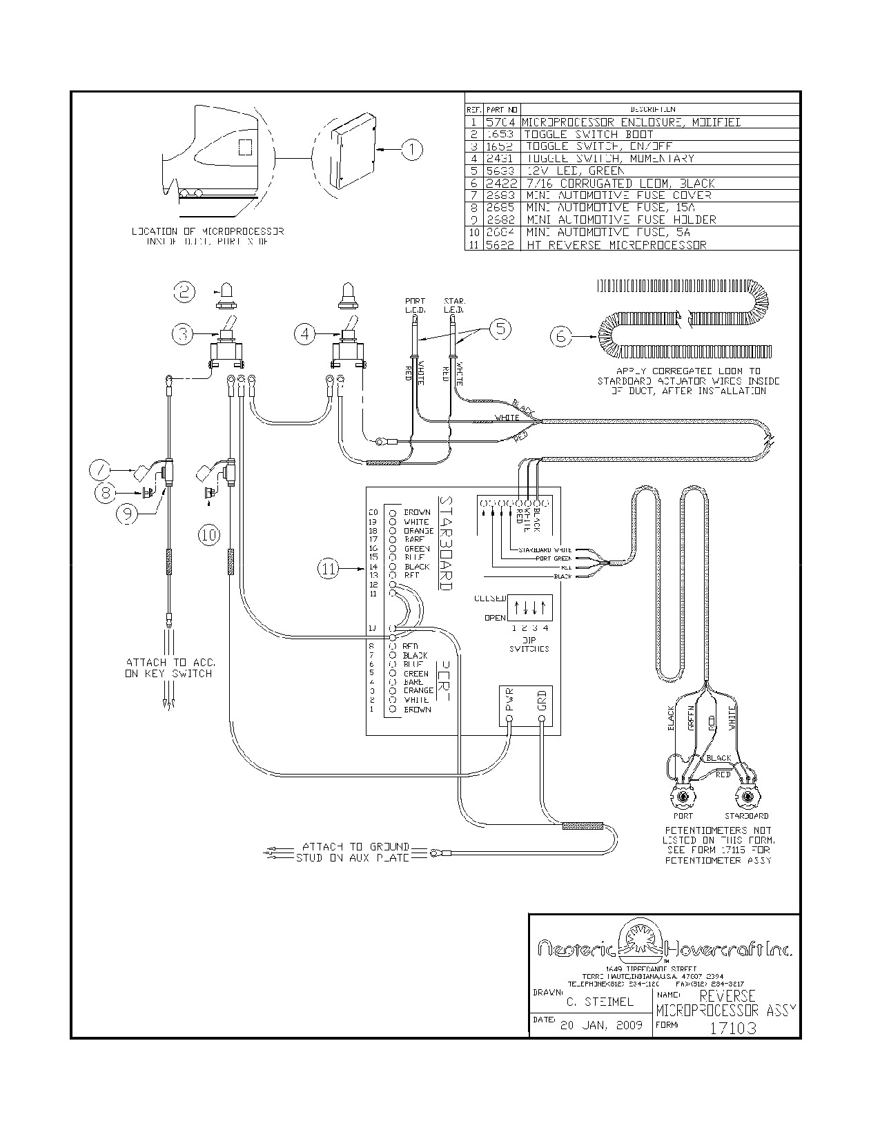
4
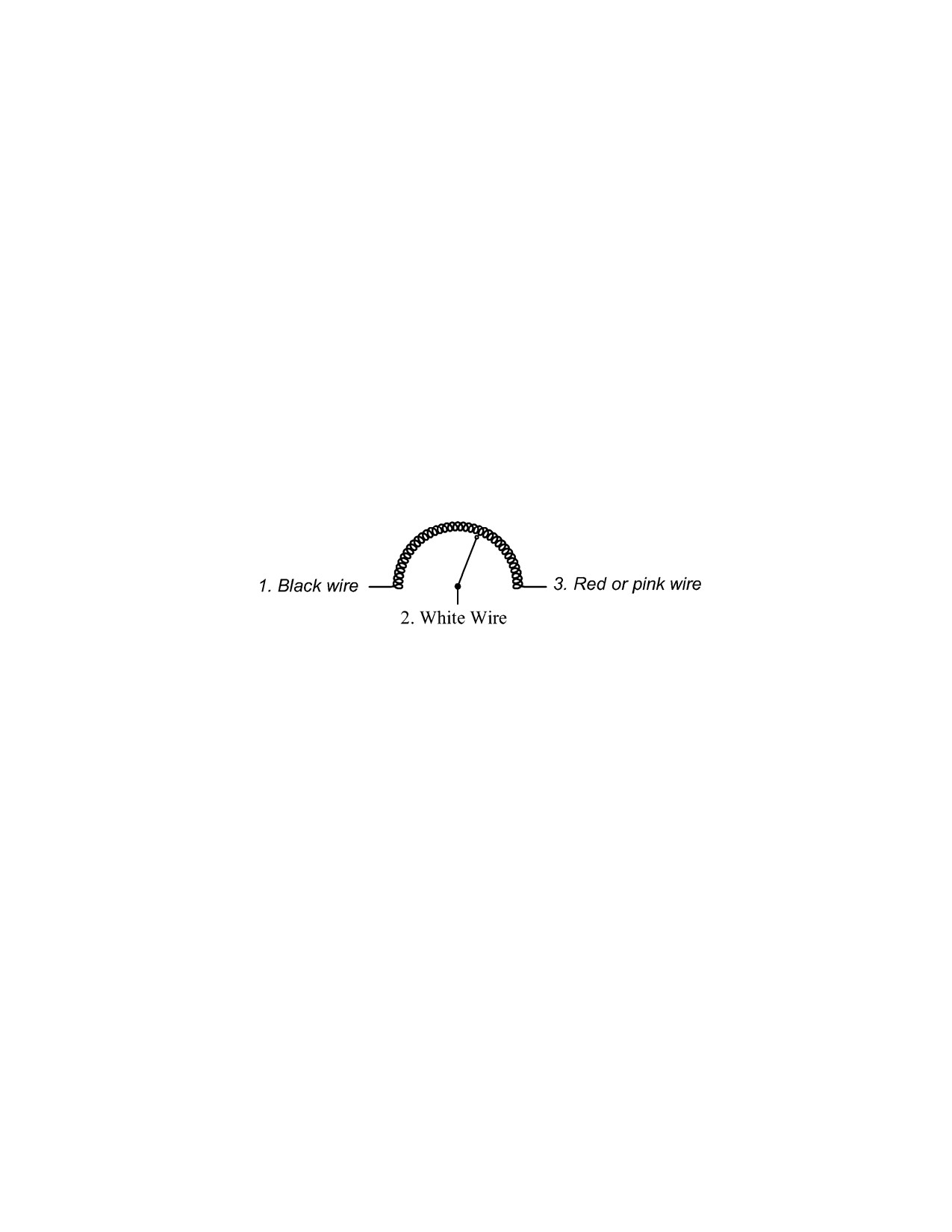
5
Testing actuator
First, disconnect actuator cable from computer.
Connect 12 Vdc to the red and black actuator wires. Measure the current; this should be 0.6
amps. If not 0.6, actuator is faulty. Reverse the 12 Vdc to black and red wires and check for 0.6
amps.
Connect 12 Vdc positive to blue and negative (ground) to green actuator wires. Clutch should
engage and hold actuator rod from moving. If rod can be moved clutch is damaged.
Attach an ohmmeter to the brown and orange wires, which are connected to the potentiometer
inside the actuator. A reading of 8 - 12 K ohms should be obtained otherwise internal
potentiometer is defective.
Attach ohmmeter to brown and white wires. Move the actuator full stroke. The ohmmeter should
read 0 -10 K ohms. If the ohmmeter shows any discontinuity, peeks or 0 ohms during the stroke,
the potentiometer is faulty.
Hand control potentiometer: This should read 0 - 10 K ohms when tested.
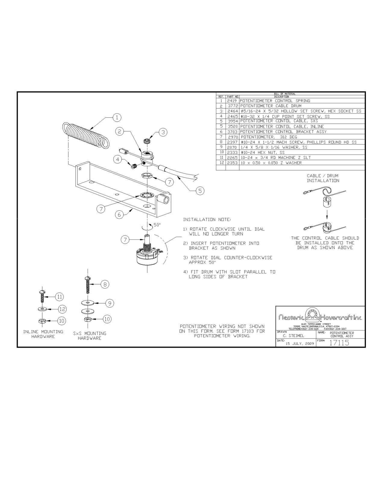
6
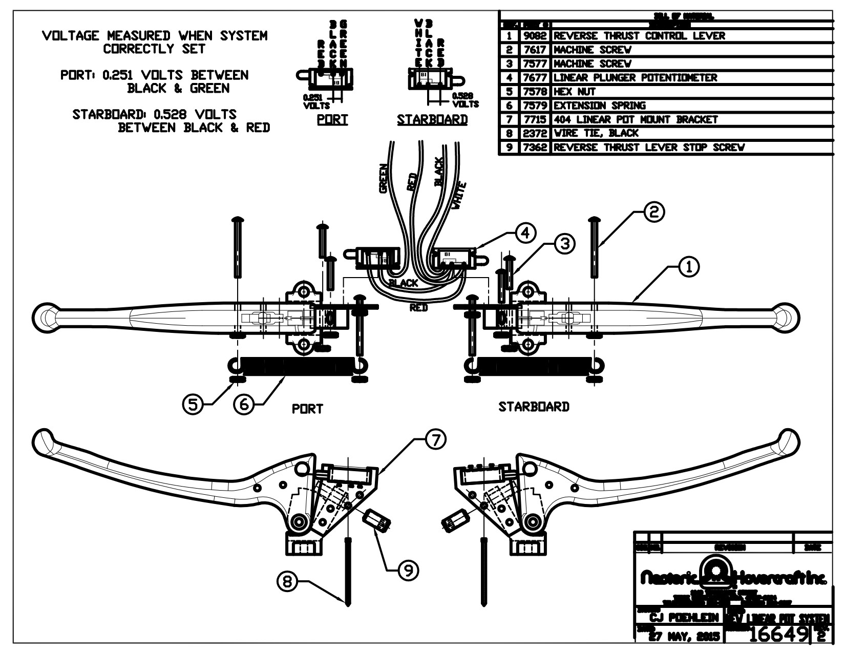

Neoteric
Hovercraft Inc.
1649 Tippecanoe Street • Terre Haute, Indiana, USA 47807-2394
TELEPHONE: 812-234-1120 • 800-285-3761 • FAX: 877-640-8507
EMAIL: Hovermail@NeotericHovercraft.com • WEB: NeotericHovercraft.com • RescueHovercraft.com
31st Jan 2020
REVERSE THRUST COMPUTER BOARD TEST PROCEDURE
By Dave Xiang
Nomenclature:
Square wave: Any signal on an oscilloscope that has a high for a certain time and low for a certain
time. The duty cycle is not exactly 50% but pretty close to it.
PWM: Pulse Width Modulation (PWM) indicates a signal on an oscilloscope that has a high for a
certain time and low for a certain time. The duty cycle is not 50%.
Main chip: The main chip is the largest chip on the computer board, it is the core chip on the board.
Power switch: Is an on/off switch on the instrument panel. Toggle the switch to ON position to give
power to the reverse thrust computer board and actuators.
Calibration switch: Is a momentary switch on the instrument panel. Flipping the switch up within 30
seconds of system bootup will result in the system entering calibration mode. Calibration procedure is
performed by turning the power switch on, followed by the calibration switch activation then hold the
reverse handlevers 100% on for 3 seconds before releasing.
1
Form: 17478
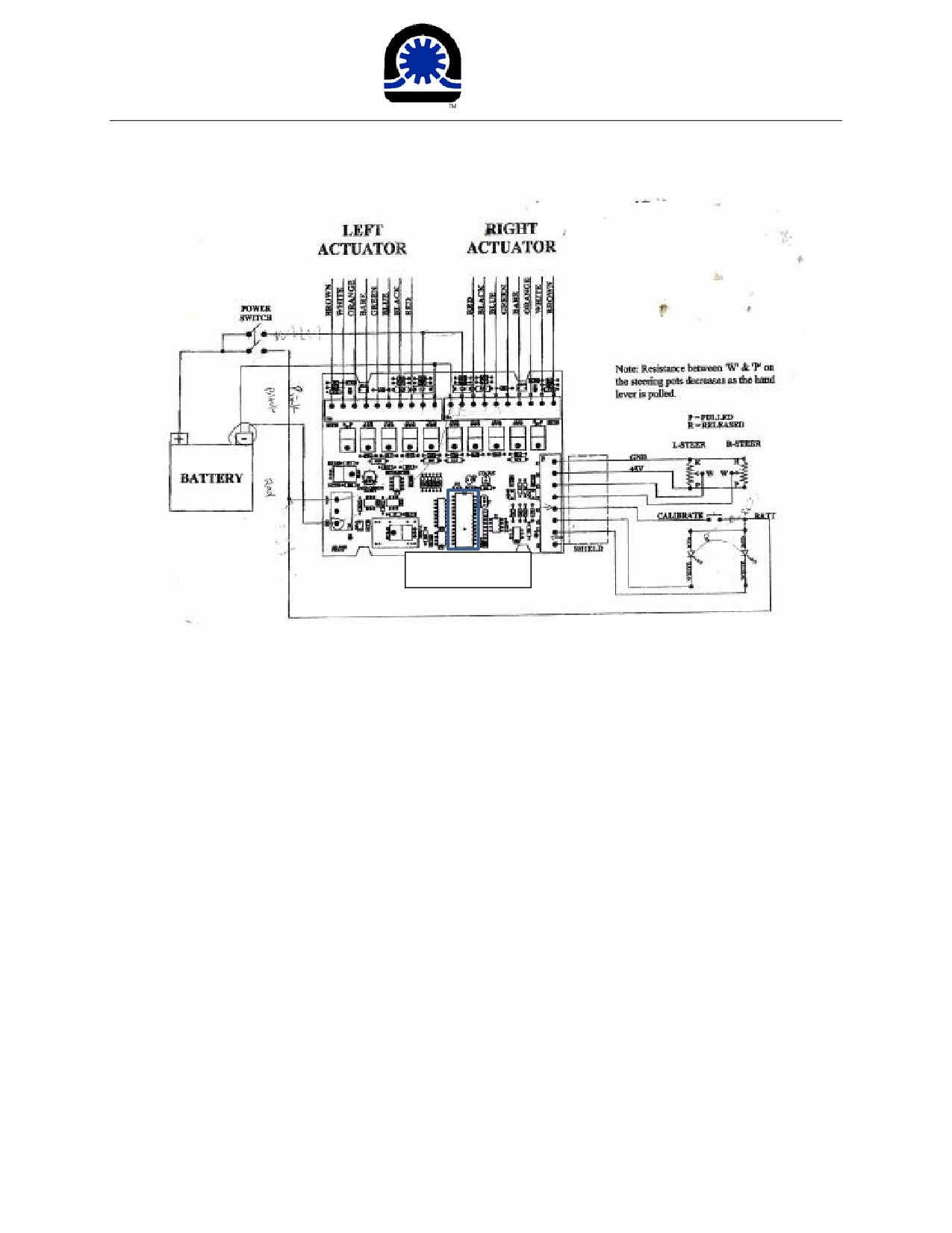
Neoteric
Hovercraft Inc.
1649 Tippecanoe Street • Terre Haute, Indiana, USA 47807-2394
TELEPHONE: 812-234-1120 • 800-285-3761 • FAX: 877-640-8507
EMAIL: Hovermail@NeotericHovercraft.com • WEB: NeotericHovercraft.com • RescueHovercraft.com
The main chip
Abstract:
The most common problem on the Neoteric reverse thrust computer is the failure of MOSFETs.
In such situations, the actuator cannot work. Replacing a pair of MOSFETs usually solves the
problem. Other problems include: unable to save calibration data, LED malfunctioning and
unable to read potentiometer, replacing the related component can sometimes fix the
problem.
Equipment:
1: 12V power supply
2: Oscillscope: Recommended an oscilloscope with at least 2 channels.
3: Digital multimeter: Usually used to test continuity. It could also be used to test input voltage.
4: Zip tags: zip tags can be useful when testing the handle bar potentiometers.
2
Form: 17478
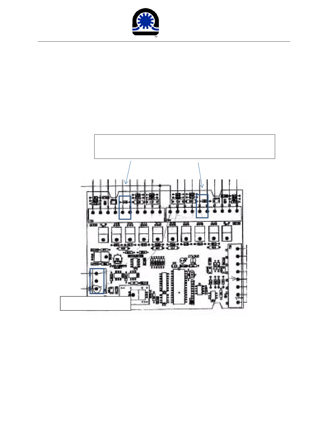
Neoteric
Hovercraft Inc.
1649 Tippecanoe Street • Terre Haute, Indiana, USA 47807-2394
TELEPHONE: 812-234-1120 • 800-285-3761 • FAX: 877-640-8507
EMAIL: Hovermail@NeotericHovercraft.com • WEB: NeotericHovercraft.com • RescueHovercraft.com
Procedure:
1: The first step is to test the continuity between 12V input and ground(GND). Disconnect all the wires
to the reverse computer board first and use the multimeter to measure the connectivity between 12V
and ground on the computer board.
If the actuator is connected here, 12V and ground would read short
because the clutch inside the actuator has a small resistance
12V and ground port
Make sure 12V and ground are not connected before proceeding.
3
Form: 17478
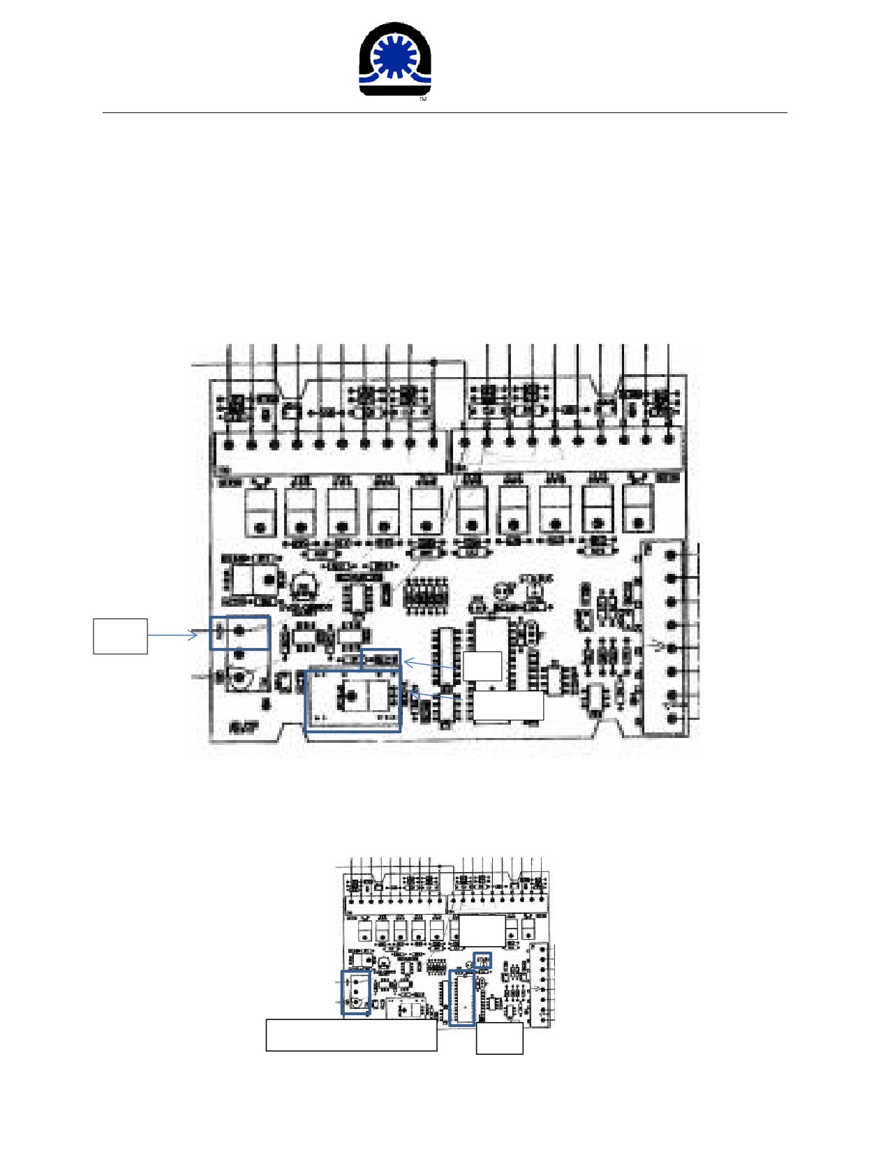
Neoteric
Hovercraft Inc.
1649 Tippecanoe Street • Terre Haute, Indiana, USA 47807-2394
TELEPHONE: 812-234-1120 • 800-285-3761 • FAX: 877-640-8507
EMAIL: Hovermail@NeotericHovercraft.com • WEB: NeotericHovercraft.com • RescueHovercraft.com
2: If 12V and ground are connected, check C1 and reg1-A. The problem could be in the DC to DC power
converter. It may take several trials to verify un-connectivity because of the circuit protection. If 12V
and ground are still connected after several trials, test reg1-A. To test reg1-A, measure the continuity
using a multimeter between 12V, and plus side of C2. Normally, they would not be connected. They
usually burn when failed. Replace reg1-A to solve the problem.
12V
C2
REG1-A
3: Test the board by connecting 12V and GND. Flip the power switch and see if the LED on the computer
board is blinking. If not, measure output on the 24th pin on IC1 during calibration using an oscilloscope. If
there is no square wave pattern, the main chip is gone. Replace the computer board.
LED
Connect 12V and GND
IC1
4
Form: 17478
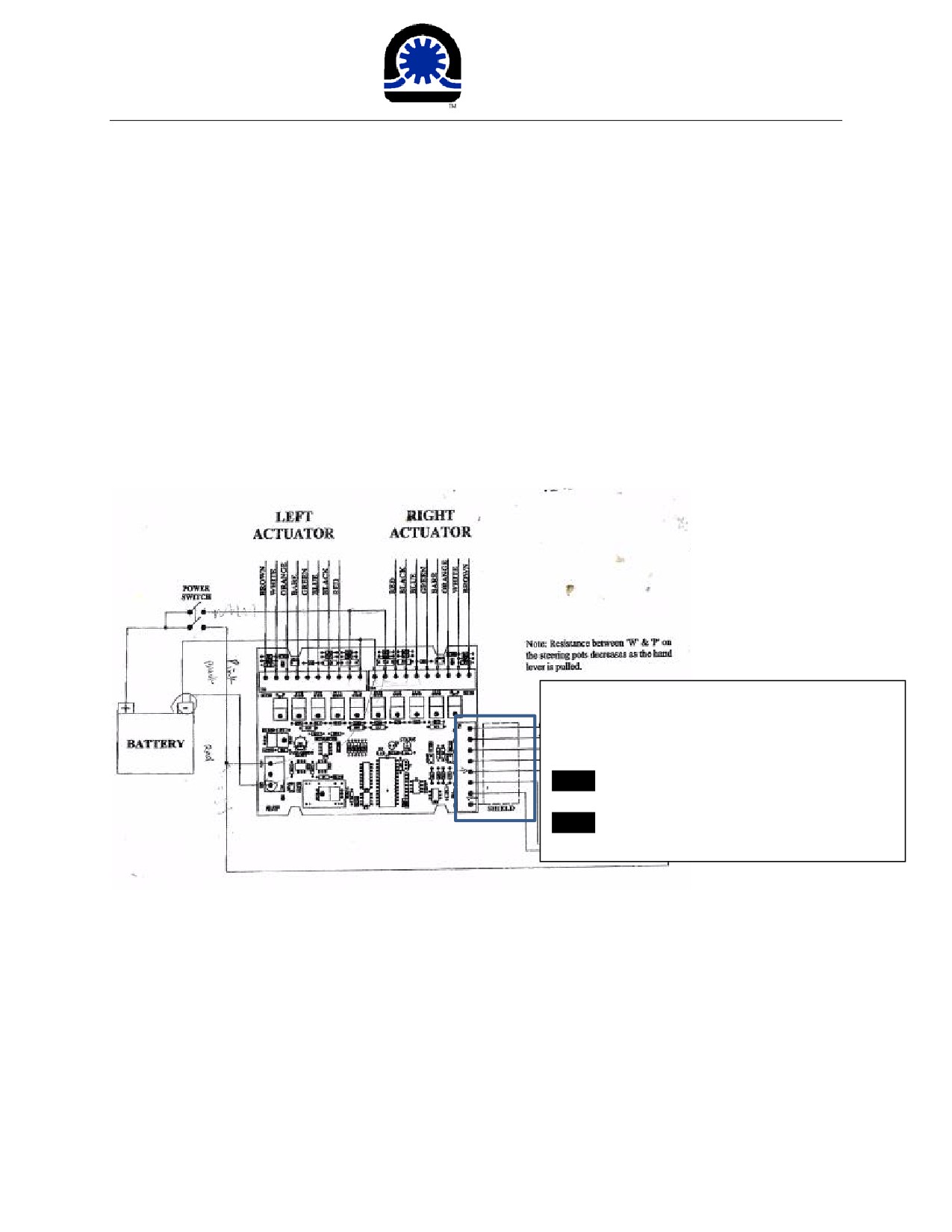
Neoteric
Hovercraft Inc.
1649 Tippecanoe Street • Terre Haute, Indiana, USA 47807-2394
TELEPHONE: 812-234-1120 • 800-285-3761 • FAX: 877-640-8507
EMAIL: Hovermail@NeotericHovercraft.com • WEB: NeotericHovercraft.com • RescueHovercraft.com
4: Further, connect the wires on the 8 pin connector. The wire color for the bottom right section from
TOP to BOTTOM should be black (Negative of handgrip potentiometer), red
(plus of handgrip
potentiometer), green
(middle port of port potentiometer), white
(middle port of starboard
potentiometer), red (calibration switch), white (port LED), black (starboard LED). (Reverse in any of the
wires may damage components on the computer board). Perform calibration. If the two LEDs on the
intrument panel blink for a while then stop, go to step 7. If not blinking, first check LED(s) by measuring
the voltage between the white wire (port LED) to GND and the black wire (starboard LED) to GND during
calibration using a multimeter or oscilloscope. If you see a square wave on the oscilloscope or get a
value between 12 and 0V on a multimeter, the LED is broken. Replace the related LED. If you do not see
a square wave or the voltage is 0V, go to step 5.
From top to bottom:
Black: Negative of handgrip potentiometer
Red: Plus of handgrip potentiometer
Green: Middle port of port potentiometer
White: Middle port of starboard potentiometer
Red: Calibration switch
White: Port LED
Black: Starboard LED
5: Check ISO1 (the white 6 pin chip), pin 1 of ISO 1 should be around 12V when calibration switch is held
on, and pin 5 of ISO1 should be close to 5V. Use an oscilloscope in this test. ISO1 functions as a bridge
that changes the 12V signal from the calibration switch to 5V going to the main chip. Replace the ISO1
when the voltage is not correct. The component name for ISO1 is 4N35. It could be found at Digikey and
other places that sell electrical components. Notice that if any voltage higher than 7V on pin 5, the main
chip may have failed.
5
Form: 17478
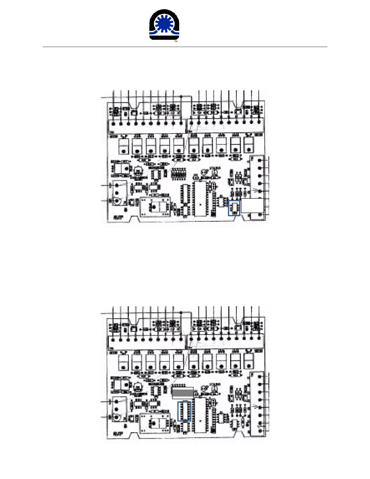
Neoteric
Hovercraft Inc.
1649 Tippecanoe Street • Terre Haute, Indiana, USA 47807-2394
TELEPHONE: 812-234-1120 • 800-285-3761 • FAX: 877-640-8507
EMAIL: Hovermail@NeotericHovercraft.com • WEB: NeotericHovercraft.com • RescueHovercraft.com
ISO1
6: Check IC4 (black 16pin chip) use the following method: Check the connectivity between pin 1 and pin
8 using multimeter when both switches are off. They are usually connected when there is a problem. To
continue checking, put two probes of oscilloscope on the following pair of pins (7&10, 8&11) while
calibrating and look at the waveform. It should show an opposite wave form (if one voltage is high,
another should be low at the same time). If the waveform is not present in pin 10 & 11, IC4 has a
problem, replace IC4 (It is a ULN2003A chip). If No wave form on both sides, the main chip is gone.
Replace the computer board.
IC4
6
Form: 17478
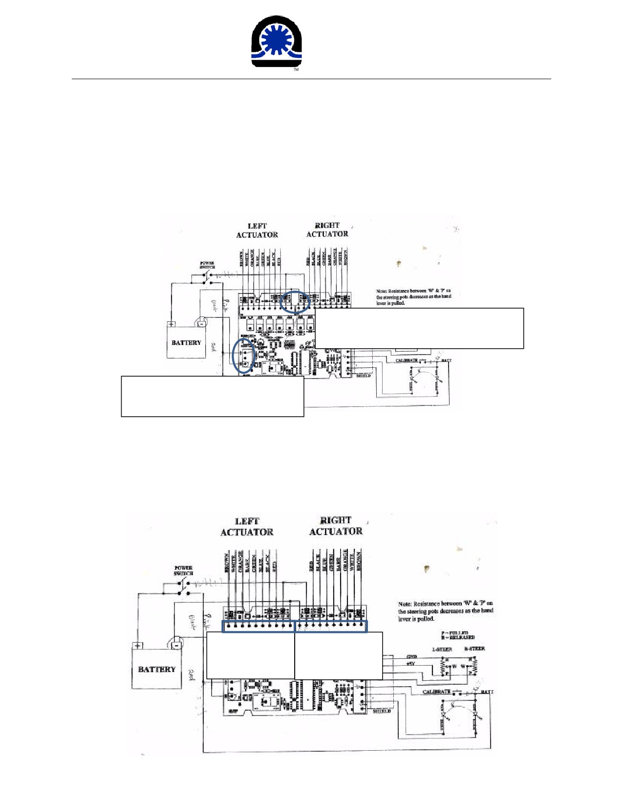
Neoteric
Hovercraft Inc.
1649 Tippecanoe Street • Terre Haute, Indiana, USA 47807-2394
TELEPHONE: 812-234-1120 • 800-285-3761 • FAX: 877-640-8507
EMAIL: Hovermail@NeotericHovercraft.com • WEB: NeotericHovercraft.com • RescueHovercraft.com
7: To test the actuator driver, connect 12V and GND to the terminal circled on the next figure. Ground
is in the middle and 12V is on the side. Leave the actuator disconnected. Measure the connectivity of
12V and ground using a multimeter. If there is continuity, at least one pair of the MOSFET has failed, go
to step 11. If they are not connected, go to step 8
Connect the circled wire, 12V on the side,
GND in the middle
Connect the circled wire, 12V on the
top, GND on the bottom
8: Flip the power on. Measure the following voltage of each port in TB3 and TB4. An oscilloscope is
preferred in this test. Pin 5 (blue) should be 12V, Pin 6 & 7 (green and bare) should be ground. Pin 8
(orange) should be 5V and Pin 10 (brown) should be ground. If any of the voltage is not seen, first
check if there are any broken traces on the circuit computer board. Then go back to step 2. REG-1A
may have to be replaced.
10,9,8,7,6,5,4,3,2,1
1,2,3,4,5,6,7,8,9,10
TB3
TB4
7
Form: 17478
Neoteric
Hovercraft Inc.
1649 Tippecanoe Street • Terre Haute, Indiana, USA 47807-2394
TELEPHONE: 812-234-1120 • 800-285-3761 • FAX: 877-640-8507
EMAIL: Hovermail@NeotericHovercraft.com • WEB: NeotericHovercraft.com • RescueHovercraft.com
9: Put one oscilloscope probe on Pin 3 (red) and one on Pin 4 (black), perform calibration. Wait for a
short period, two Pulse Width Modulation waveform (PWM) should appear on the oscilloscope. As
indicated by the following picture. If any one of the signals is not present, check IC4 (in step 6) and
MOSFETs (step 10). Otherwise, go to step 12
(image achieved by attached channel 1 to Pin 3 of TB3 channel 2 to Pin 4 of TB3)
This step could also be done by using two multimeters. Switch them to measure 20V DC. Put the black
lead on multimeter on any of the ground Pin 1 on TB3 or TB4. Put one of the red lead multimeters on Pin
3, and one on Pin 4. You should see one of the multimeters go high (lager than 8V) and then low (less
than 5V), as one multimeter goes low, the other multimeter should go high. If any one of the signals is
not presented, check IC4 (in step 6) and MOSFETs (step 10). Otherwise, go to step 11.
8
Form: 17478
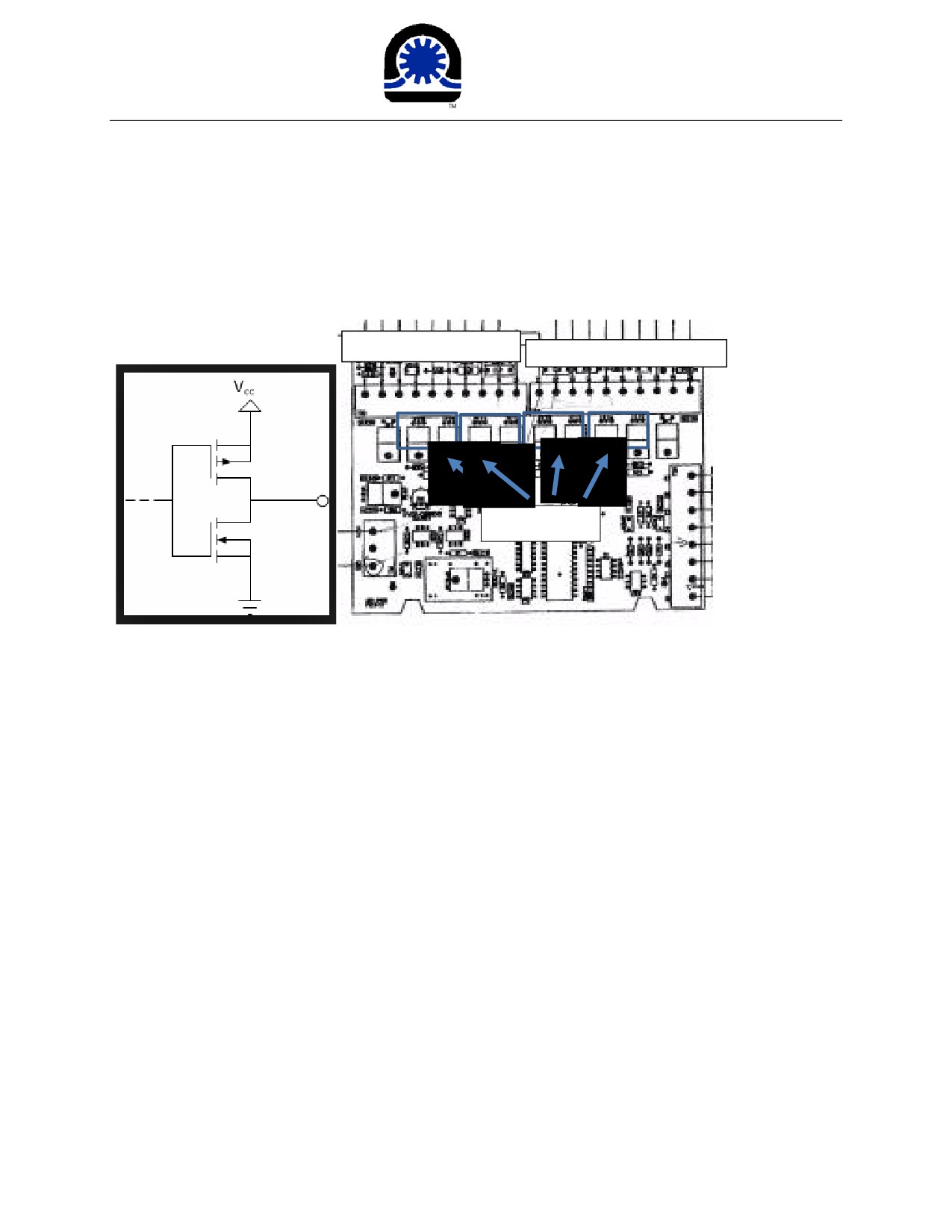
Neoteric
Hovercraft Inc.
1649 Tippecanoe Street • Terre Haute, Indiana, USA 47807-2394
TELEPHONE: 812-234-1120 • 800-285-3761 • FAX: 877-640-8507
EMAIL: Hovermail@NeotericHovercraft.com • WEB: NeotericHovercraft.com • RescueHovercraft.com
10: Check MOSFETs: There are four pairs of MOSFETs on the reverse computer board. Each pair consist
of an N-channel and a P-channel MOSFET. It is a H bridge motor drive with some circuit protection. The
simplified structure is the following:
10,9,8,7,6,5, 4, 3,2,1
1,2,3,
4, 5, 6, 7, 8, 9,10
MOSFET Pairs
Usually, the bad pair of MOSFET would not give the waveform as indicated in the oscilloscope figure.
Check if there are any burn marks or black traces around MOSFET(s) to locate the problem. Use a
multimeter to measure the connectivity to trace which pair of MOSFETs has failed. If any MOSFET goes
wrong, two of three legs would be connected. MOSFET 1,2 are a pair, MOSFET 3,4 are a pair, MOSFET
5,6 are a pair, MOSFET 7,8 are a pair. When replacing MOSFETs, it is IMPORTANT to replace both. Do
NOT replace one in the pair, because the broken one can break the other. Those MOSFETs are P-channel
IRF9540N and N-channel IRF540N. Those two MOSFETs have exactly the same appearance, READ THE
MOSFET NAME TO MAKE SURE WHICH IS WHICH. Reversing the order would burn both MOSFETs.
11: If there is no problem in the pervious steps, connect the actuator. Connect both actuators on the
computer board and start testing the whole system. Turn the power on to see LED on the computer
board is blinking. Flip the calibration switch, and hold the handlevers for 3 seconds. See rods on actuator
extended to the maximum and then to the minimum. Then go roughly to the middle according to the
position of the two handlevers. After that, the two actuators can be controled by using the two
handlevers.
9
Form: 17478
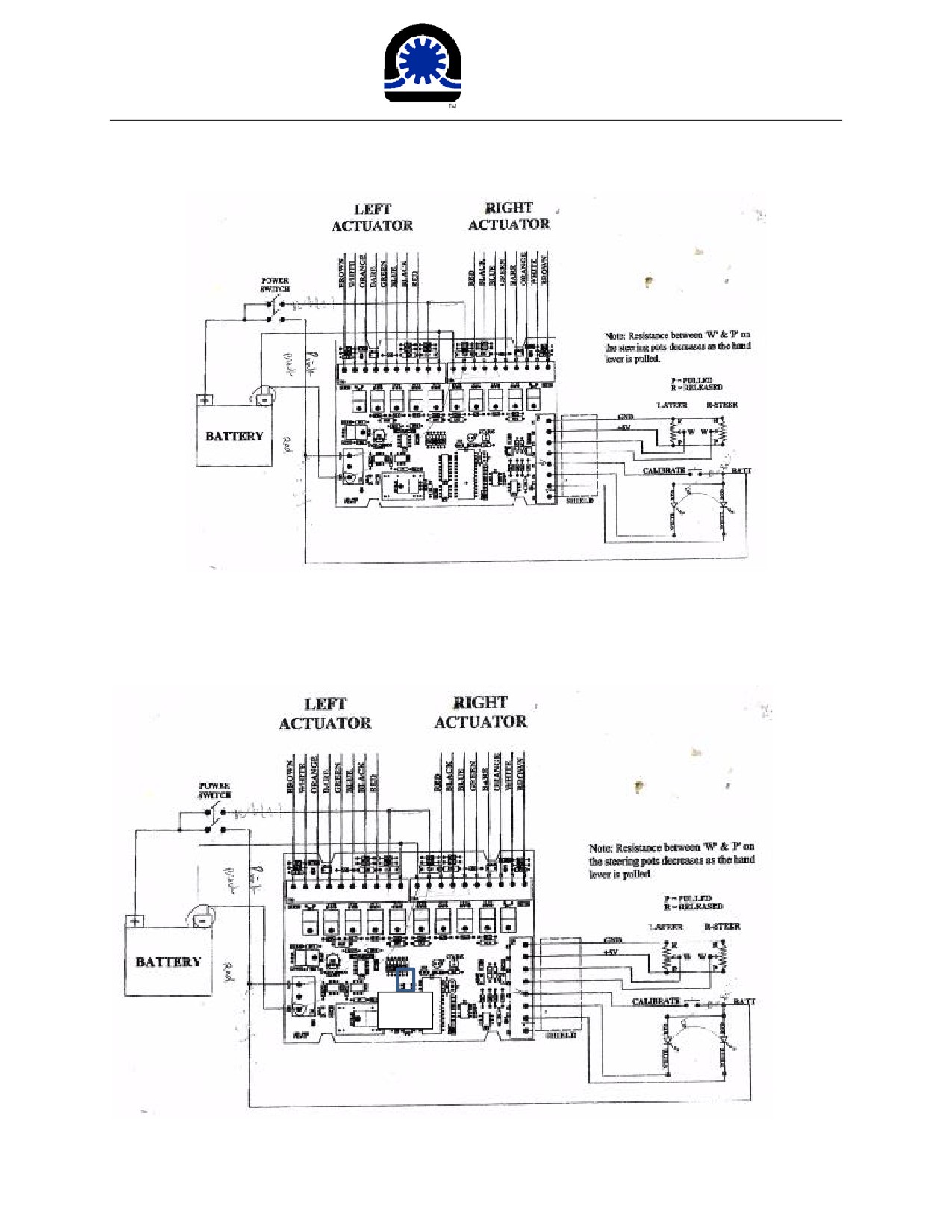
Neoteric
Hovercraft Inc.
1649 Tippecanoe Street • Terre Haute, Indiana, USA 47807-2394
TELEPHONE: 812-234-1120 • 800-285-3761 • FAX: 877-640-8507
EMAIL: Hovermail@NeotericHovercraft.com • WEB: NeotericHovercraft.com • RescueHovercraft.com
12: Finally, turn off the power switch and wait for 3 seconds. Then turn it on. Now actuator can be
controled without reclibration. If that is not happening and error code 6 appears, something is wrong
with IC3 (black 8pin chip). The IC3 is in charge of storing calibration data when the power is off. If that
happens, replace the IC3. It is an EEPROM named AT93C46D. Replacing IC3 will solve the problem.
IC3
10
Form: 17478
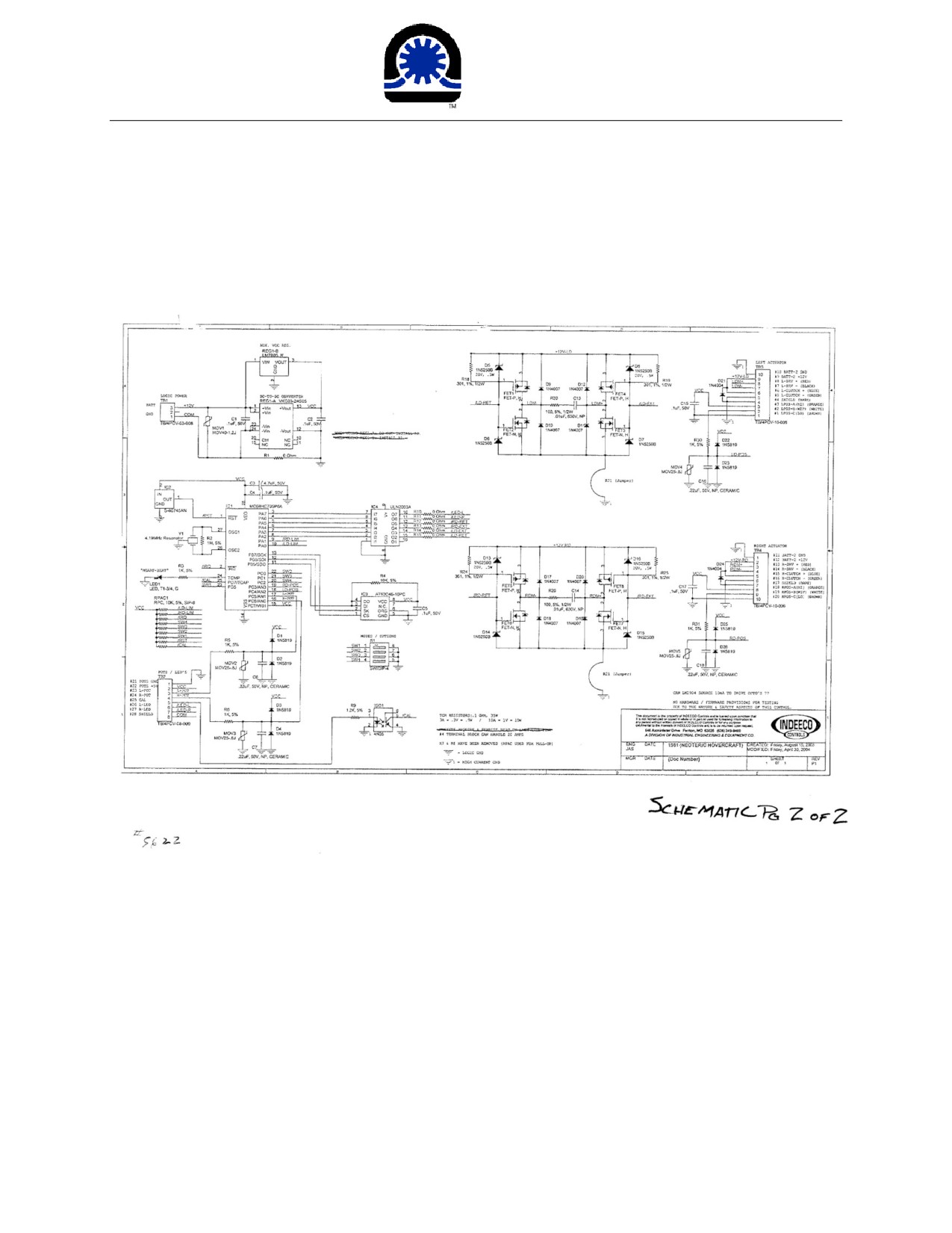
Neoteric
Hovercraft Inc.
1649 Tippecanoe Street • Terre Haute, Indiana, USA 47807-2394
TELEPHONE: 812-234-1120 • 800-285-3761 • FAX: 877-640-8507
EMAIL: Hovermail@NeotericHovercraft.com • WEB: NeotericHovercraft.com • RescueHovercraft.com
13: Reaching this step without finding any problem means the computer board is good.
Schematic of the reverse thrust computer board.
11
Form: 17478
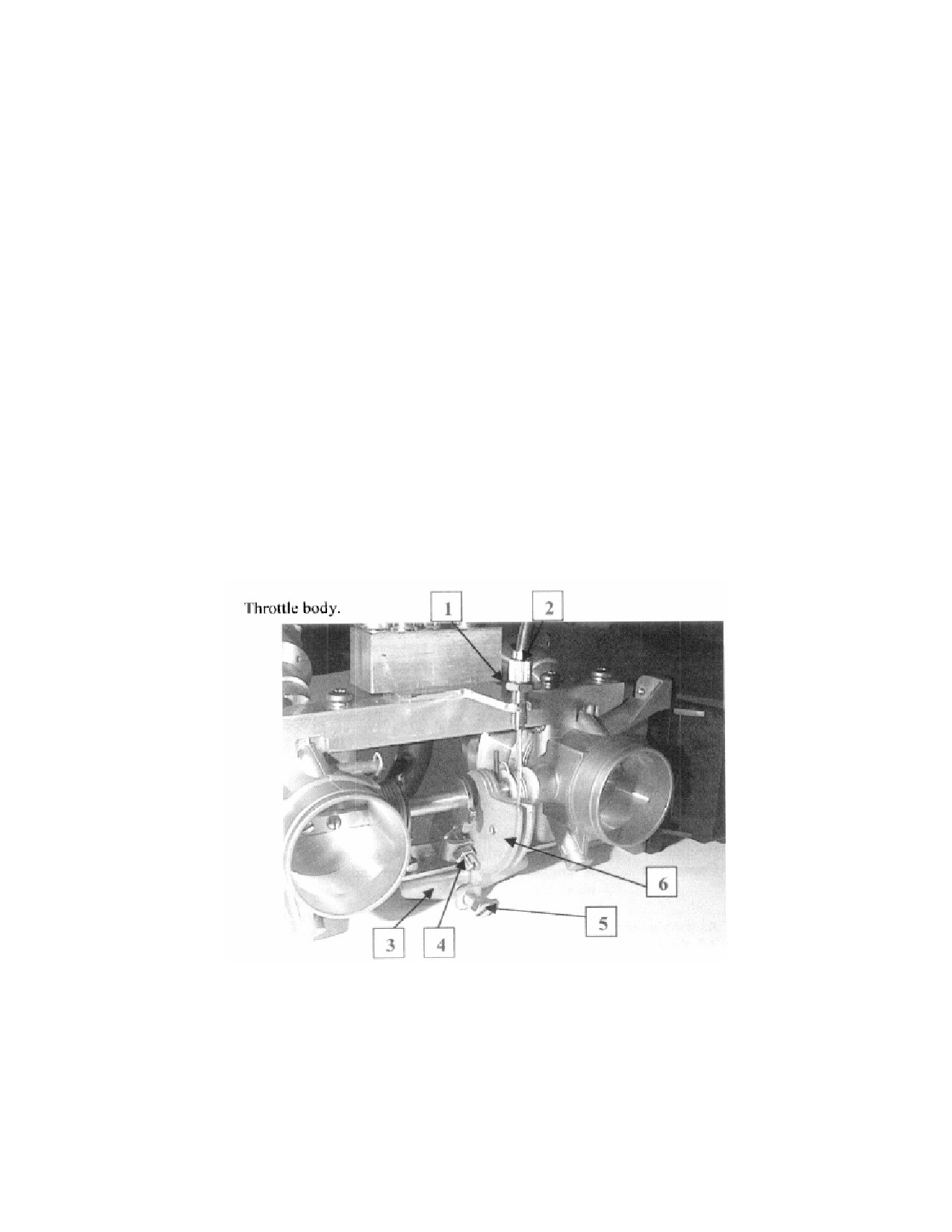
General description of the fuel injection
The applied fuel injection system is a
sequential multipoint fuel injection. The throttle body injection is
installed instead of the carburetor. Both throttle body injection (TBI) units are connected at the bell
crank and are synchronized with each other through the throttle body shaft.
The fuel pressure is 42 Lbs. PSI. This is produced through an electric fuel pump and
stays consistent
with the help of a pressure regulator.
. Min voltage is 10v.
To avoid interruption from contaminated fuel, a series of fuel filters are installed fore and aft of the fuel
pump.
The amount of fuel is controlled through the injector nozzle (governed by the throttle position/RPM}.
The dosage is refined through different adjustment parameters.
The following parameters are used for the calculation of fuel ratio-amount of injection:
• Throttle position
• RPM
• Ambient air temperature
• Barometric pressure
• Engine crankcase temperature
• Acceleration rate
• Manual manipulation (optional)
Position # Description
1
Throttle cable tension adjustment stop nut
2
Throttle cable tension adjustment
3
Throttle stop plate
4
Synchronization adjustment screw (do not change)
5
Idle stop adjustment screw
6
Throttle bell crank
Assy 17309 Form 17117
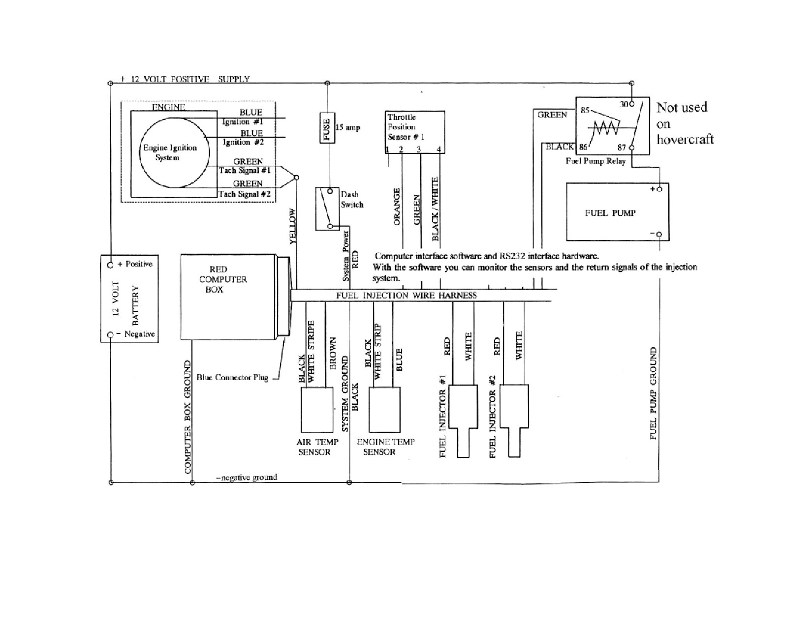
ELECTRICIAL CIRCUIT DIAGRAM
Form 16949
NOTE: Fuel Injection components and parts can be found under
65HP Engine Manual.
Hirth US Distributor, RPE, Matt Dander Feb 2020
How to determine if Fuel Injection tach signal is working.
In order for the fuel injectors to activate at the correct time the Fuel Injection Computer, ECU needs
to know the RPM of the engine. This information is delivered from the CDI box(s) as a tach pulse.
Each CDI box(s) has a green wire that carries the tach signal. Both green wires on dual ignition
engines are connected to a yellow wire from the fuel injection wiring harness. This yellow wire
delivers the tach signal to the ECU. If the tach signal is never received from the CDI box(s) the
ECU does not know the engine is turning and does not deliver any fuel. To find out if there is a
missing tach signal turn on the power to the ECU, then advance the throttle to 65% open. A buzzing
noise coming from the injectors should be heard.
Every time the throttle goes from idle to past 65% open, the ECU turns all injectors to full power
for 1 second. The injectors rattle making the buzzing sound and a quantity of fuel is shot into the
engine. Return the throttle to about 20% and turn the engine over with the starter
(put ignition switch(s) in run position). The injected fuel will make the engine run for about 2
seconds and then stop. This test proves that the ECU is receiving power and working, the engine
ignition system is working but the ECU is not getting the tach signal, if it were the engine would
continue to run. If the tach signal is the problem then track down why. As mentioned above the
circuit from the 2 green wires from the CDI box(s) to the yellow wire in the ECU plug must be
complete. If the yellow wire is broken then the signal can not get through. If the wire is OK but the
terminal in the ECU plug is corroded the signal can not get through. If after inspection the tach
signal wiring turns out to be sound then 2 other possibilities exist.
The reason both green wires from the CDI(s) are attached to the yellow wire is for redundancy. If
one of the ignition system fails on dual ignition systems the tach signal from the remaining ignition
system keeps the engine running. In rare cases a CDI can go to ground internally and ground out the
tach signal. Since it is wired directly to the other CDI it can also ground out the signal of the other
CDI that is still working properly. To determine if a bad CDI is the problem separate the green
wires. Break the splice where the 2 green wires come together and attach only one to the yellow
wire from the wiring harness. Make the injectors buzz again, pull throttle to 20% and crank. If the
engine now continues to run then the connected CDI is bad. If it will not stay running switch the
yellow wire to the green wire from the other CDI and repeat the test. Can only do this on dual
injection systems. If the engine now continues to run the CDI tested previously is bad. If a bad CDI
turns out to be the culprit replace it and wire it as previously. If both tests fail to reveal a bad CDI
then the problem is in the ECU.
When the yellow wire delivers the tach signal to the ECU it is read with an input device within the
ECU. This device in turn sends the tach signal to an internal processor. If the input device should
fail the signal does not get through. If the wiring is good and that both CDI's are good then the only
thing left is the ECU. To confirm plug in another ECU that is known to be good and start the
engine. If the engine runs then the original ECU must be bad. Obtain a new ECU to perform this
test or send the suspect ECU in to the Hirth repair center to have it tested. After testing proves it bad
it can be repaired or a new ECU is purchased but at least by having it tested the next step is obvious.
Form: 16556
Additional Fuel Injection Comments
If the engine will run when you squirt fuel in but stops when the fuel is gone. First advance the
throttle to 65% to force it to purge the fuel, (buzzing noise). If it does not squirt fuel for 1 second
then the problem is in either the injector driver in the ECU, or the injector common wire (red) is
broken, or the injector driver wire (white) is broken. If it does squirt fuel then the problem is in
the tach signal. Either the CDI is not generating a tach signal, (green wire). or the ECU is not
accepting the signal or the yellow tach signal wire from ignition to ECU is broken.
Appendix B
0-1
Appendix B
Additional Information for Engines with Oil Injection
Attention: The chapter on Oil Injection (Appendix B) is only to be used in connection
with the service manual for the corresponding engine type. All sections of
the manual, with exception of the chapters concerning lubrication, are
from here on still fully valid. Please read all instructions before installing
the engine or its operation.
General Directions:
In order to provide for the continuing further development of our products we have to reserve
the right to make changes in the size of deliveries, in form, technical execution, and
equipment. We also ask for your understanding that no claims can be made based on
information contained in this manual.
Göbler-Hirth Engines KG, Max-Eyth-Str. 10, 71726 Benningen, Germany
16.02.05
DOC_Anhang_B_E_0.01
Page 1 of 12
Appendix B
0-1
Table of Contents:
1.
Description of Oil Injection
1.1. General description of oil injection
1.2. Names and description of individual parts
2.
Installation Instructions
2.1. Mechanical installation
2.2. Hydraulic installation
2.3. Installation instruction
2.4. Additional Measures to Ensure Safety of the Construction
3.
Operation of the System
3.1. Operational means
3.2. First time operation
3.3. Operation of the oil injection system
4.
Maintenance/Service Intervals
5.
Diagram
5.1. Hydraulic diagram
6.
Trouble shooting
16.02.05
DOC_Anhang_B_E_0.01
Page 2 of 12
Appendix B
0-1
1
Description of Oil Injection
1.1
General description of oil injection
An oil pump transports the two stroke oil directly from a container into the intake manifold
and in special constructions also directly to hard to reach areas to be lubricated (for example:
top bearing when vertically installed [H30; H32]).
The oil pump is fastened to the recoil starter or to a support of the fan housing and is
connected by way of the clutch directly to the crankshaft.
With the exception of the H30, H37 and the H32, the oil ratio depends on 2 variables.
1. Number of rotations
2. Throttle position (loaded condition)
The oil ratio of the H30, H37 and the H32 depends solely on the engine rpm.
1.2
Names and description of individual parts
•
Oil container (sketch 5.1 pos. 5)
Function:
Reservoir for the two stroke oil for the oil injection
Minimum amount of oil:
F30, H30, 3701 und H37 > 2,5 Liter
All others > 1,5 Liter
1. Filling socket with air vent
2. Connection of oil line to oil pump
•
Oil level indicator and/or warning light (sketch 5.1. pos. 4)
Function: Gives information about present oil level and/or warns when below
minimum level.
•
Oil filter (sketch 5.1. pos. 3)
Function:
Cleaning the oil from foreign parts which may damage or conjest the oil
injection system.
•
Oil pump (sketch 5.1. pos. 2)
Function:
To dispatch and measure out the oil for the suction sockets and the areas
to be lubricated.
The oil pump consists of the following main components:
1. Rope disc and Bowden cable holder (pict. 1)
Function: Guide for load depending regulator for the amount of oil
Note:
With motors of the H-series the amount of oil will only be changed in
connection with the rotation number. Therefore, the lever has been adjusted and set
at the factory and may not be changed.
2. Oil connections (pict. 1)
Function: The connection from oil pump to motor has been factory-installed. The
open oil connector is for the connection from the oil reservoir.
16.02.05
DOC_Anhang_B_E_0.01
Page 3 of 12
Appendix B
0-1
2. Installation Instructions
The following instructions have to be adhered to for a safe and trouble free operation
2.1. Mechanical Installation (oil pump control):
• Install a "splitter" into the throttle cable for the carburettor - i.e. throttle valve control.
• Install a Bowden cable between splitter and oil pump.
• Measure and cut the end of Bowden cable and affix lead seal.
• Hang Bowden cable into guide disc.
For 2-cylinder engines:
• Open carburettor i.e. throttle valve completely and adjust the Bowden cable to the
required length (pict. 1a).
Attention:
please note that the respective marks on control dial of oil pump are to
be understood only as the minimum settings requiring the final
adjustment to the desired mixture ratio.
Remarks:
For engines with
2 carburettors or throttle valve sockets, the
2
carburettors, i.e. throttle valves first have to be synchronized to each
other, before adjusting the oil pump.
For 3-cylinder engines:
• keep the basic engine setting from factory or adjust the engine without load
(e.g.
propeller) to idle speed 1400-1500 rpm
Stop the engine and keep position of throttle valve in idle position.
Harmonize mark on oil pump housing and line mark on sheave.
In general:
• Secure the adjusting screw with counter nut.
• Activate throttle control several times, then check the adjustment and if necessary
readjust. Repeat until the setting does not change anymore.
• Check that the Bowden cable to the oil pump action is not bent and runs smoothly.
Furthermore, assure that the Bowden cable can not be damaged by sharp edges or nearby
heat, etc.
• Check that the Bowden cable can not jump from the guide disc.
Note:
The amount of oil may not be reduced by changing the setting of the guide
disc, because too lean an operation in the partial load may cause serious engine
damage. There is no way the operator can adjust the amount of oil.
2.2. Hydraulic Installation:
• The oil reservoir must be situated higher than the oil pump, since the oil pump can not
begin suction independently.
• An oil filter has to be installed between the oil reservoir and the oil pump in order to avoid
damage or clogging of the oil pump.
• All lines have to be attached in sufficient distance to hot parts (i.e. exhaust system).
• The oil lines have to be laid out in such a way, that they may not be damaged by sharp
edges.
• The oil lines must not be bent. They have to be secured in such a way that bending can not
occur even during operation.
• For safety, hose clamps must be affixed to all connections of the oil lines.
16.02.05
DOC_Anhang_B_E_0.01
Page 4 of 12
Appendix B
0-1
2.3. Installation Instruction
1. Mount the engine as described in the individual service manual.
2. Mount the oil reservoir as described in section 2.2 above.
3. Connect oil reservoir and oil pump, insert an oil filter into the line.
4. Ensure that the necessary amount of oil can flow from the oil reservoir to the oil pump.
To do this, hang the oil hose into a measuring cup at the level of the pump, fill 200 ml
2 stroke oil for the oil injection into the oil reservoir. Clock the time between the
beginning and the end of the oil flow.
5. For engines H30, F30, 3701, the 200ml must have run through a maximum of 20 min.
For engines 2702-2706 and H32 E, 30 min maximum. When measuring, the oil- and
surrounding temperature should be between 10-20°C. Should the passage take longer
than stated, the position of the oil reservoir has to be changed accordingly until the
flow condition described is reached.
6. Connect the oil hose to the entrance of the oil pump and secure with a hose clamp.
7. Fill oil reservoir with 2 stroke oil for the oil injection.
8. Vent the oil pump by opening the air vent screw (pictures 1a and 1b). Wait until the
oil exits the bore hole without bubbles. Then the vent bore hole must be closed again.
16.02.05
DOC_Anhang_B_E_0.01
Page 5 of 12
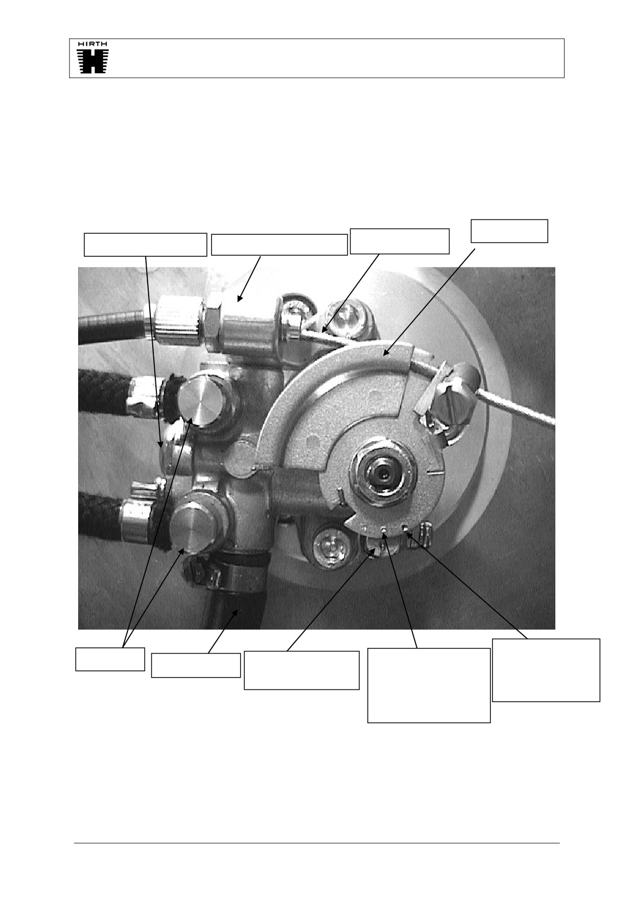
Appendix B
0-1
Picture 1a: Front view of Oil pump all engines except 3 cylinder models.
Cab disc
Bowden cable
Air vent screw
Bowden cable holder
Full gas mark
Oil exits
Full gas mark 2706.
Oil entrance
Marking Oil pump
F23, 2704, 3202,
3203 and 3503
case
3502 (minimum)
(minimum)
and H32 adjustment
16.02.05
DOC_Anhang_B_E_0.01
Page 6 of 12
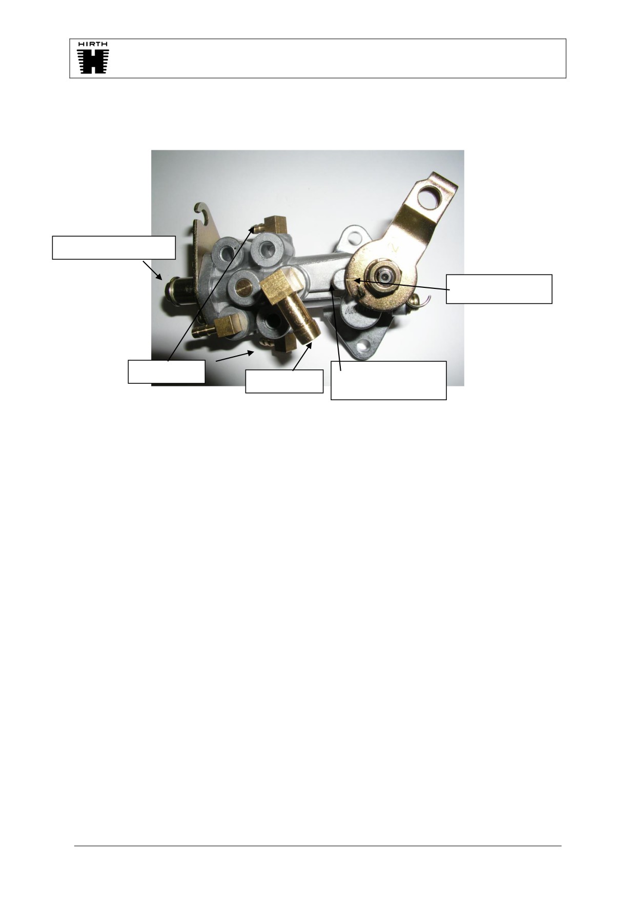
Appendix B
0-1
Picture 1b: Front view of oil pump (3-cylinder engines)
Air vent screw
Idle mark 3 cyl.
Oil exits
Marking oil pump
oil entrance
case
2.4 Additional Measures to Ensure Safety of the Construction:
The following measures are not necessary for a secure operation of the installation.
1. Install a fill level indicator into the oil reservoir to control the oil level.
2. Install a warning light when going under the minimum amount of oil.
Recommendation: The setting for the minimum amount of oil should be chosen so
as to ensure that the remaining amount of oil is sufficient for the
entire fuel tank capacity.
3. Check the used amount of oil in relationship to the used amount of fuel in order to be
able to react in time to a blocked or worn out oil pump.
Note:
The consumption of oil is strongly influenced by the fuel setting. If the
engine is operated with various loads the oil consumption may vary
also.
3. Operation of the System
3.1. Operational means
Only brand name 2 stroke oils may be used. They have to be suitable for oil injection
and must be labeled accordingly.
For safe engine operation and least wear Göbler-Hirth Engines recommends
BlueMax AL 2-stroke oil.
16.02.05
DOC_Anhang_B_E_0.01
Page 7 of 12

Appendix B
0-1
3.2. First Time Operation:
1. Fill fuel tank with at least 10 liters of pre mixed fuel (1:50).
2. Start engine and let idle.
3. Manually completely open guide disc of the oil pump (see picture 1).
4. Check that oil lines fill evenly with oil.
5. After all oil lines have filled with oil, reposition guide disc to the idle position.
6. Let engine run for another 5-10 minutes and turn off.
7. Check all oil lines for leaks and whether the oil pump setting is still correctly
adjusted.
8. Operate engine with the rest of the mixture, before refuelling.
3.3. Operation of the Oil Injection System:
See chapter 4 about maintenance and service intervals.
Before each operation it is necessary to ensure, that the oil reservoir contains a
sufficient amount of oil for the planned time of operation, since an interruption of the
oil supply may lead to serious engine damage.
16.02.05
DOC_Anhang_B_E_0.01
Page 8 of 12
Appendix B
0-1
4. Maintenance-/Service Intervals
Oil injection needs no service with the exception of the components described on the
chart.
The following service and checks must be executed:
Nr.
Description
Timeinterval
In beginning
Then every
After (hours)
(hours)
1
5
10
25
1.
Check setting of oil pump
X
50h
2.
Check whether oil filter is clean
X
25h
3.
Check whether oil pump setting is functioning
Before each operation
4.
Check oil level in the reservoir
Before each operation
5.
Check the hydraulic system for leaks
Before each operation
The following parts have to be replaced:
Nr.
Name
Exchange
intervall
1.
Oil filter
Each 200h
2.
Oil pump
Each 1000h
16.02.05
DOC_Anhang_B_E_0.01
Page 9 of 12
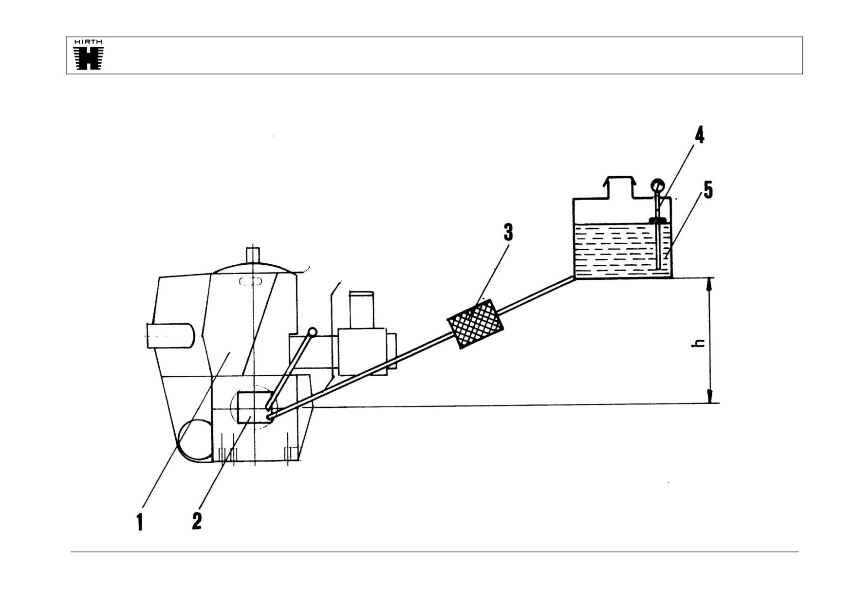
Appendix B
0-1
5. Diagram
5.1. Hydraulic Diagram
1
Engine
2
Oil pump
3
Oil filter
4
Oil level gauge
5
Oil reservoir
h
>=0
16.02.05
DOC_Anhang_B_E_0.01
Page 11 of 12

Appendix B
0-1
6. Trouble Shooting
Attention, should it become clear that no or too little oil is being moved, the engine must immediately be changed to a
lubrication mixture of 1:50 until the problem is solved, otherwise serious damage to the engine may occur.
Problem
Cause
Control
Elimination
Insufficient oil flow
Oil pump setting not properly
See Chapter 2.1.
Readjust oil pump setting
adjusted
Oil filter blocked
Check amount of flow (see Chapter 2.3. Pos.5)
Exchange filter
Too much oil flow
Oil pump setting not properly
See Chapter 2.1
Read just pump setting
adjusted
No or too small amount of
Defektive injection valve
Exchange injection valves and check whether or not the defect
Replace injection valve
oil in one channel
changes too.
Oil line blocked or pinched
Check oil lines visually
Exchange oil line
Oil pump defective
Measure amount of oil flow of all channels without injection
Exchane oil pump
valve and with new lines
No amount of oil flow
Inflow stopped up, Oil filter
Check amount of flow (see Chapter 2.3. Pos.5)
Exchange filter
blocked
Oil pump defective
Measure amount of oil flow of all channels without injection
Exchange oil pump
valve
16.02.05
DOC_Anhang_B_E_0.01
Page 12 of 12

Oil injection tips
The oil injection pump pushes oil to the injectors but does not draw oil from the reservoir
tank. The pump is gravity feed so your choice for mounting the reservoir tank must be
high enough that the outlet on bottom of tank is at least 1” higher than the supply inlet
hose barb on the pump. In the case of a tractor prop installation the tank will be lower
during climb than in level flight so it may be necessary to mount the tank 2 or 3 inches
higher than the pump. Use ¼” hose with the supplied oil filter in between pump and tank.
Make sure the oil filter is installed with the oil flow arrow toward the pump.
This is a variable rate oil injection system meaning the RPM of the engine combined with
the position of the cable disk on the front of the pump will determine the ratio. The cable
disk must be connected to your throttle cable system so that as you increase throttle the
disk moves as well which increases the oil flow. On a tractor prop application this can
simply be a 3rd cable run all the way to your quadrant. On pusher applications the
quadrant will be much farther away from the engine and the small spring on the pump
cable disk may not be strong enough to pull the cable back when you go to idle. This is
where a 3 way throttle cable splitter can come in handy. You can purchase a cable splitter
from Aircraft Spruce. The oil injection manual shows how to initially adjust the cable. On
2 cylinder engines after cable is installed bend the retaining tab over to keep it in place.
Once installed and reservoir tank filled you need to bleed the air out of the pump. There
is a small bleed screw on the side of the pump that you turn out a few turns to bleed the
air. Once the air is gone and oil begins to come out tighten the bleed screw. There is still
air in the injection lines that can not be bled out until engine is started and until it is there
will be no lubrication. For your first run you need to premix your first tank of fuel at 50:1
ratio. This will keep engine lubricated until the oil injection system is functioning. Pull
the black plastic protective sheath that is around the oil lines back at each injector far
enough that you can see the white oil line on each. After engine is started monitor the
line. When the air is gone and oil is all the way to the injector you will be able to see it in
the line. You can shove the sheath back into place. Once the oil is flowing make a mark
on the tank that reflects the oil level. Also record how much fuel is in the fuel tank. Start
the break in procedure. Before you refill fuel tank record how much fuel you used for
break in. Refill oil tank until you are back at your mark measuring exactly how much oil
is required to refill it. Now do the math to determine what ratio of oil you are getting. As
an example if you used 8 gallons total for the break in and 14.5 ounces of oil your ratio is
70:1. - 8X128 ounces in a gallon = 1024 ounces of fuel divided by 14.5 = 70:1 oil ratio.
70: to 1 is the correct ratio. If the ratio found on the survey is substantially less than 70:1
increase the amount the cable disk on the pump is actuated by adjusting the cable adjuster
on the oil pump to increase it. If you are using too much oil adjust the cable adjuster so
that the cable disk is opened less. Keep doing short surveys (1 gallon of fuel at 5000Rpm
per survey) making adjustments until the required ratio is achieved. When you are
confident engine is receiving sufficient oil from the oil injection system (70:1) to operate
safely you can stop premixing oil with the fuel and begin running straight gas.
Size of reservoir tank: You want to choose an oil reservoir tank that will not run empty
before the fuel tank does. If your oil ratio is 70:1 a 1 gallon oil reservoir tank would

provide enough oil for 70 gallons of fuel. A 3 quart tank would cover 52 gallons, a 2
quart tank is good for 35 gallons and a 1 quart tank would be good for 17.5 gallons of
fuel. If you had a 10 gallon fuel tank a 1 quart oil tank would be more than enough oil for
each tank full but would have to be refilled each time the fuel tank is refilled. With 2
quarts of oil you could run 3 full tanks of fuel before refilling the oil tank. There are
various reasons for oil injection failures but by far the largest percentage of failure is
forgetting to refill the oil tank. For this reason some users will choose the 1 quart tank
and just get into the habit of refilling it at the some time they add fuel. Also it takes up
less room. You want to use a translucent oil tank that allows you to see the oil level at a
glance to insure you always have enough before you leave.
Recommended oil ratios: Blue Max 2 cycle injection oil - 70:1
Off the shelf mineral based 2 cycle injection oils - 60:1
Synthetic 2 cycle oils: 45:1 for pure synthetic - 50:1 for synthetic/mineral blends
Note: Hirth does not recommend the use of any type or blend of synthetic oil.
Do not use Blue Max pre mix oil in an oil injected engine.
Engines with recoil starter: On 2 cylinder in line engines the oil pump is installed on the
recoil starter. Too avoid shipping damage to the pump we sometimes remove the pump
and the oil line clamp and store it alongside the engine in a small plastic bag. Also inside
the bag are the two 5mm pump mounting bolts. Simply line up the pump driving slot with
the pump shaft, push the pump into place and install the two 5mm bolts with blue
locktight on the threads. (25 inch pounds) Note that one of the 5mm bolts is longer than
the other so be sure to install them in the correct mounting foot on the pump. Install the
oil line clamp to the recoil starter case with the spacer between the clamp and the recoil
case. Use Blue loccktight on the threads and torque to 86 inch pounds.
Re positioning the recoil handle: If you decide you want the recoil handle to exit the
engine in a different direction it is possible to pull the 3 mounting bolts out and turn the
recoil. You will first have to remove the oil pump. When re installing the recoil it is
imperative that it is centered with the crankshaft. To center the recoil install all 3 screws
(with blue locktight) until they are just snug and you can still move the recoil slightly.
Snap the recoil handle out hard until it catches but do not pull the engine over. Hold the
tension on the handle with one hand and tighten the 3 recoil mounting bolts with the
other. Now pull the handle out about a foot and let go. If the handle recoils back easily
you have the starter centered and you can go ahead and torque the 3 mounting bolts to 86
inch pounds. If the handle has drag when you let go loosen the 3 bolts and repeat the
centering procedure until the recoil is centered. If you pulled the recoil off the engine
make sure the rubber insert that goes between the pump shaft and the crankshaft is still in
the coupling and that the coupling is lined up before you push the recoil in place. If you
let the rubber insert fall out the coupling will shear off in a short time and you will have a
total failure of the lubrication system. Now that the recoil is in a new position you will
find the pump mounting holes no longer line up. Remove the pump mount plate from the
front of the recoil, turn it until the pump mount holes are again in correct position then re
install the plate mounting bolts with blue locktight 925 inch pounds) and then re mount
the pump as per pump mounting instructions previously mentioned above.
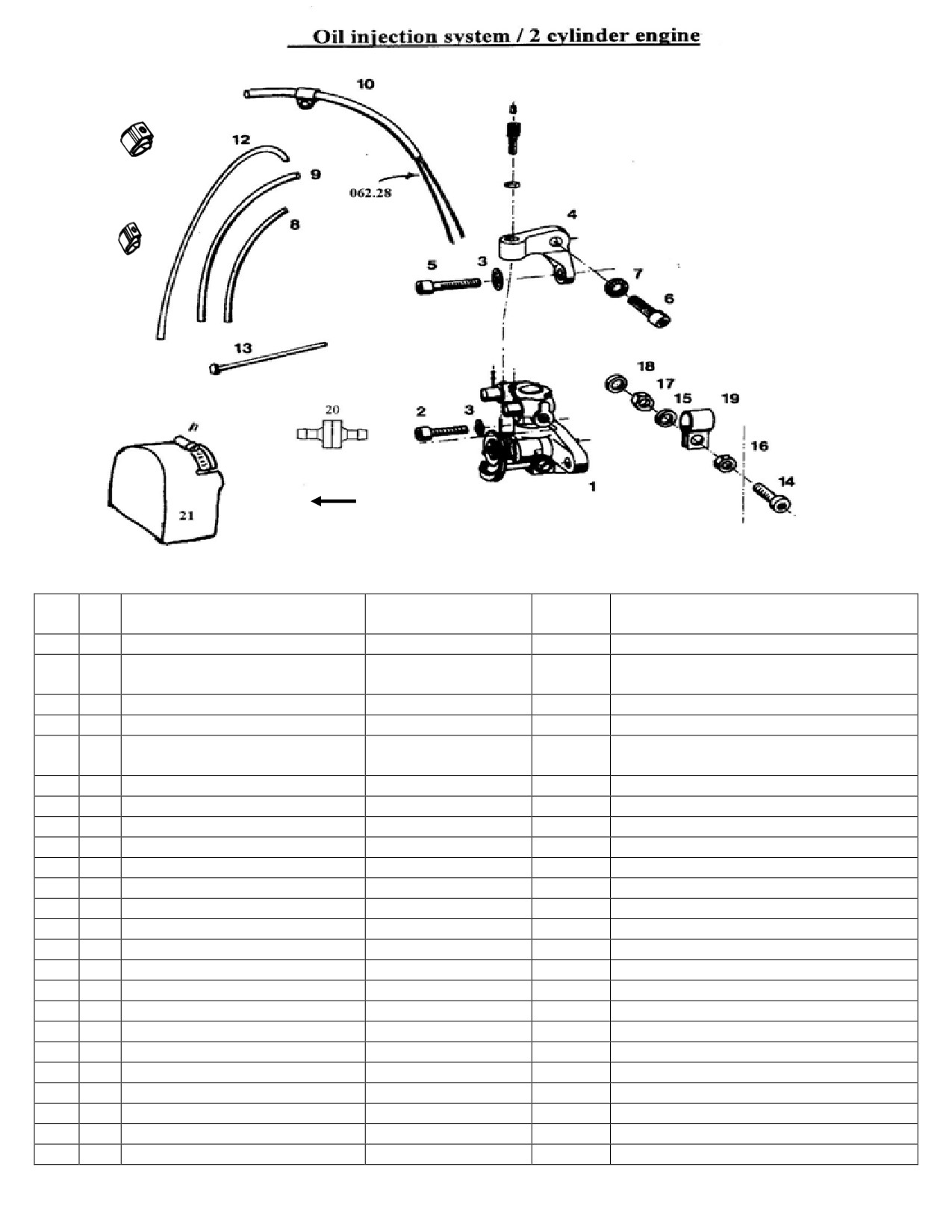
11
22
23
19
24
Arrow = Flow Direction
On Filter
Fig.
Neoteric
No.
Designation
Hirth Ref. No
Notes
No
No.
1
1
Oil pump
045.9
5426
Shorter (port side) oil pump schs .Loctite
2
1
Cylinder screw
D912M5x16
243
3
2
Locking washer
053.8/5
Belleville washer under pump mount shcs
4
1
Cable adjuster holder
3211 A3
Aluminum bracket to attach cable
Cylinder screw (Timing Adj.
Longer (starboard side) oil pump
5
1
D912 M5X20
Hardware)
shcs.Loctite 243
6
1
Cylinder screw
D912 M6X12
2469
Holds cable adjuster in place.Loctite 243
7
1
Serrated Locking washer
053.8/6
6902
Belleville washer under DIN912M6X12
8
1
Isolating hose
D40621 B5X0,6/140
7128
Short single oil line cover (black)
9
1
Isolating hose
D40621 B8x0,7/330
7129
Long single oil line cover (black)
10
1
Hose
062.28/380
3425
Supply hose front 13” long
11
4
Hose Clamp (small)
5646
Clamp hose to tank & Filter
12
1
Hose
063.28/500
3425
Supply hose rear 16 ¼” long
13
1
Cable tie rap
026.40
2372
Zip tie, do not use
14
1
Cylinder Screw
Din 912 M6x25
Do not use
15
2
Washer
DIN 125 B6,4
6916
Do not use
16
1
Hexagon head screw
DIN 985 M6
5572
Do not use
17
1
Hexagon head screw
DIN 934 M6
Do not use
18
1
Washer
DIN 433 6,4
Do not use
19
4
Hose clamp (smaller)
5489
Clamp hose to pump & carbs
20
1
Oil Filter
5505
Inline oil filter Arrow = Flow Direction
21
1
Splash Cover
6246
Fiberglass part, Neoteric manufactures
22
1
Adjusting Screw
6105
Oil Injection Cable Adjuster Screw
23
1
Adjusting Screw Nut
6106
Nut to lock adjuster screw
24
1
3” Hose Clamp, SS
2734
Hose clamp for splash cover
Form: 17283rev4
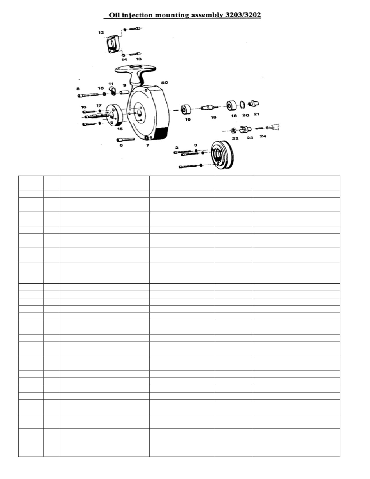
Neoteric
Fig. No
Qty
Designation
Hirth Part No.
Notes
Part No.
1
1
Driving Dog with starter
275Y3U
6189
Dog Pulley
2
3
Cylinder Screw
DIN 6912M8X35
Dog Pulley hardware, SCHS
Md=23-28Nm
3
3
Tab washer
053.8/8
Belleville washer under
DIN6912M8X35
50
1
Recoil
275AF1U
5471
Pull Start
6
2
Cylinder screw
DIN 912 M6X35
6911
Pull Start Hardware SCHS
Md=9,6…11 Nm
7
2
Spring Ring
DIN7980 6
6940
Pull Start Hardware, Belleville
washer under DIN912M6X35
8
1
Cylinder screw
DIN 912 M6X50
2479
Pull Start Hardware SCHS (Only
applies to 5471 pull start long
screw)Md=9,6…11 Nm
9
1
Spacer pipe
264 H4
6935
Pull Start Hardware
10
1
Washer
DIN 125 B6,4
6916
11
1
Pipe clamp with rubber
063.24
6697
Small #8 clamp
12
1
Solenoid starter
195 A1
13
2
Cylinder screw
DIN 912 M8X30
2348
Starter SCHS bolt
14
2
Spring ring
DIN 127 B8
Belleville washer under
DIN912M8X30
15
1
Mounting Plate
3211 A4
Round plate on front 5471
16
3
Cylinder screw
DIN 912 M5X16
SCHS holds on round plate
3211A4
17
3
Serrated tab washer
053.8/5
Belleville washer under
DIN912M5X16
18
2
Deep groove ball bearing
DIN 625 6200 2RS/C3
6887
Located inside 5471
19
1
Shaft
3211 A5
Located inside 5471
20
1
Locking ring
DIN 472 30X1,2
Located inside 5471
21
1
Coupling right
3211 A8
Located inside 5471
22
1
Coupling element
040.4/2
Rubber coupling element. Loctite
243
23
1
Coupling left
3211 A7
Aluminum coupler engine side.
Loctite 243 -reverse threaded
24
1
Threaded pin
DIN 913 M6X20 LH
Reverse thread set screw that
attaches 3122A7 to the
crankshaft. Loctite 243-reverse
threaded
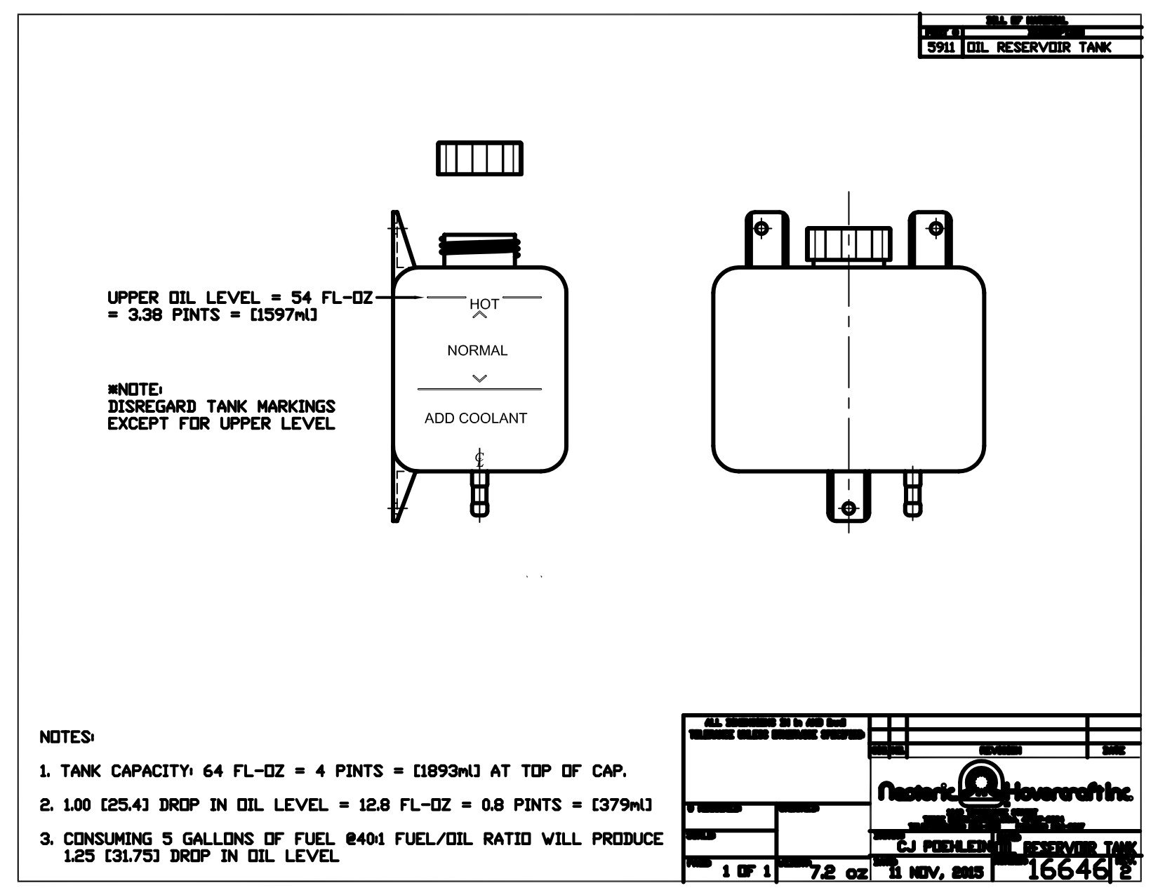
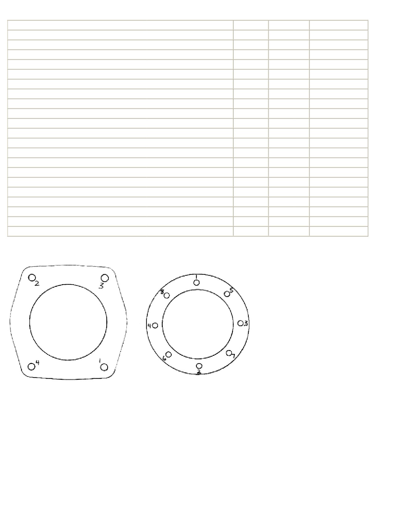
TABLE OF TORQUE VALUES 55 AND 65HP ENGINE
TORQUE
Fastener Description
Size
Ft. lb
inch/lb
AIR GUIDE ATTACHMENT SCREWS AND BOLTS
6mm
6 Ft.Lbs
72 inch Lbs.
CYLINDER HEAD SCREWS
6mm
8 Ft.Lbs
96 inch Lbs.
ELECTRONIC IGNITION BOX & IGN. COILS NUTS
6mm
7 Ft.Lbs
84 inch Lbs.
FAN HOUSING MOUNTING SCREWS
6mm
8 Ft.Lbs
96 inch Lbs.
FLYWHEEL DUST COVER (265C1)
6mm
6 Ft.Lbs
72 inch Lbs.
INTAKE MANIFOLD MOUNTING SCREWS
6mm
7 Ft.Lbs
84 inch Lbs.
RECOIL STARTER MOUNTING SCREWS
6mm
8 Ft.Lbs
96 inch Lbs.
CRANKCASE ASSEMBLY SCREWS 2703
8mm
19 ft.Lbs
228 inch Lbs.
CRANKCASE ASSEMBLY SCREWS 3203
4-6mm bolts
6mm
8 Ft.Lbs
96 inch Lbs.
FAN PULLEY MOUNTING SCREWS
8mm
19 ft.Lbs
228 inch Lbs.
ELECTRIC STARTER MOUNTING SCREWS
8mm
19 Ft.Lbs.
228 inch Lbs.
CYLINDER BASE NUTS
8mm
19 Ft.Lbs.
228 inch Lbs.
EXHAUST MANIFOLD MOUNTING SCREWS
8mm
19 ft.Lbs
228 inch Lbs.
RUBBER INTAKE FLANGE SCREWS (2702/03)
8mm
12 Ft.Lbs.
144 inch Lbs.
RUBBER INTAKE FLANGE SCREWS (3202/3203)
6mm
8 Ft.Lbs
96 inch Lbs.
COOLING FAN MOUNTING NUT
10mm
37 Ft.Lbs.
444 inch Lbs.
REDUCTION DRIVE MOUNTING SCREWS
10mm
37 Ft.Lbs.
444 inch Lbs.
SPARK PLUGS (cold engine) (2703/3203 single ignition)
14mm
14 Ft.Lbs.
168 inch Lbs.
CRANKSHAFT BOLT (PTO-end) (½ inch NF)
½” NF
55 Ft.Lbs.
660 inch Lbs.
CRANKSHAFT NUT (Magneto end)
16mm
107 Ft.Lbs
ENGINE MOUNTING BOLTS
½” NC
44 Ft.Lbs.
528 inch Lbs.
For items not listed, contact Neoteric
Criss cross torque patterns for
cylinder base
nuts and cylinder
heads. Repeat
torque pattern in 1 /3
increments until final torque spec is
reached.
Assy 17322
Form 16934

General Tools
Tools:
1. Inch pound torque wrench 0 to 250 in/lbs
2. Allen wrench set including 2.5, 4, 5, 6, and 8mm
3. Ball wrench set including 5 and 6mm at least
4. Open end wrenches 7, 8, 10, 13, 17, and 19mm
5. Regular and Phillips screwdrivers
6.
3/8" drive hex bit set including 2.5, 4, 5. 6, and 8mm
7.
5/8" or 13/16" spark plug sockets depending on spark plug size
8. Wrist pin puller (optional, only needed if removing pistons)
9. Ring Compressor for 72mm or 76mm diameter pistons
10. 3/8" drive ratchet
11. Piston Ring Remover (optional)
12. ¾" socket
13. 24mm socket
14. T25 and T20 torx bits (FI engines only)
15. Spark plug gap setter/checker
16. Soft faced hammer and ball peen hammer
17. Timing light (optional)
18. Exhaust spring remover and installer
19. 0-250 ft/lbs torque wrench (optional used only flywheel nut and G-50)
Materials
1. Loctite 242 or 243 blue
2. High temp anti-seize
3. Acetone
4. Hylomar gasket dressing (Permatex 25249)
5. Assembly lube (straight 2 cycle oil)
6. Aviation form-a-gasket (Permatex 3D)
7. Loctite 271 red
8. Loctite 518, 574 or equivalent (block sealant)
9. Mild acid (used to remove
Specialty Tools
Specialty tools (available at RPE):
1. Flywheel puller
2. Base nut torque wrench (preset to 19 ft/lbs)
3. Seal setters W137
4. Crankshaft PTO bearing spacer
5.
17mm Allen wrench G-50 gearbox
6. Snap ring pliers
7. Dial indicator and holder for timing
8.
40mm socket for prop shaft nut
Form 17326

Assembling Hirth Top End
Some tips on re-assembly that may be helpful
VERY IMPORTANT: When installing the piston on to the connecting rod, note the small arrow
imbedded in the top. THIS ARROW MUST POINT TO THE EXHAUST PORT! If you put the
piston on backwards, the piston and the cylinder will be ruined in about 10 hours of run time.
Piston rings must have small gap at the ends pointing up. A size cylinder must be used with A
size piston, B cylinder with B piston and C cylinder with C size piston. Make sure all mating
surfaces are clean. Con Rods are marked with a paint dot or etched with a letter (W, R, B) this
indicates which needle bearing to use.
Use Omni Visc Silicone to seal block halves and all joints. Use Permatex Gasket Dressing on
Gaskets.
IF IT IS A 2-CARB INLINE ENGINE: (Or F30 4 carb/Injected). After you have the cylinders
on, only snug the nuts tight enough that you can still move the cylinder a little. Now put the
exhaust manifold on without gaskets and snug the bolts. This will insure your cylinders are
parallel with each other and prevent exhaust leaks. Now, you can torque the cylinder base nuts to
1/3 of full torque. Use a crisscross torque pattern. After 1st 1/3 torque pass remove exhaust
manifold. Now repeat the same criss-cross pattern to 2/3's torque, then a third pass at full torque
(19 ft. lbs.) Once the cylinder is fully torqued, you can install and torque the exhaust manifold
with the exhaust gaskets.
Use a criss-cross torque pattern on head bolts also in 1/3 increments. (96 inch pounds) It is very
important to use an accurate inch pound torque wrench on heads and spark plugs.
IF IT IS A SINGLE CARB ENGINE: (Or F30 2 carb) Procedure is the same as 2 carb except
you must use the intake manifold to align cylinders instead of the exhaust manifold. This is
important to prevent intake gasket leaks.
Use blue loctite 242 on both the 8mm base nuts and the 6mm intake manifold bolts. DO NOT
use loctite on the exhaust or head bolts. (It will boil inside the holes)
You may want to consider using Permatex - Hylomar HPF gasket dressing (Part#25249) on all
the brown paper type intake gaskets to be sure of your seal. Do not use gasket dressing on used
gaskets. (This is optional-gaskets can be installed dry as well) Never use a sealer designed for
metal surface sealing on paper gaskets as it cannot cure and will leak. Torque 8mm rubber carb
flange bolts to 120 inch pounds.
If piston and rings are new, engine will have to go through break-in again. Cylinder head bolts
should be re-torqued within 10 hours. It is important to check the torque of the cylinder base nuts
within 10 hours of putting engine back in service. (19 Ft. Lbs.)
*Use torque specs in the manual for all fasteners involved.*
Form 17322 Form 17273

Top End Disassembly
Tools needed:
•
5mm Allen wrench
•
3/8" drive 5mm Allen wrench
•
10mm socket (fan cooled engines only)
•
3/8" drive ratchet
•
13mm open end wrench
•
6mm Allen wrench
•
5mm Allen ball wrench
•
Circlip remover
•
Wrist pin puller
•
Spark plug socket 5/8" or 13/16"
•
Marker or something to keep parts together
•
Plastic or rubber faced hammer
Procedure:
1.
Make sure ignition is turned off and battery is disconnected to reduce risk of injury.
2.
Remove exhaust system including EGT probes.
3.
Remove spark plugs.
4.
Remove air guide from fan cooled engine or free air scoop from free air engine.
5.
Remove carbs or fuel injection (you can simply let the carbs or FI hang on the cables and
hoses).
6.
Remove intake manifold.
7.
Remove all head bolts (you may want to mark your heads for reassembly later, example
pto, mag).
8.
You may want to remove the fan tower or flywheel cover for easier access to the base
nuts on the cylinders.
9.
With a 13mm open end wrench, remove all 4 base nuts from each cylinder needed to
work on (mark the cylinder for reinstallation later as mag or pto).
10. To remove the pistons, you will need to first remove at least one circlip from each piston
(I usually remove the pto end circlip from each piston), (throw the circlips away, they are
not to be used over) with either a wrist pin puller or a soft round piece of material, push
or pull the wrist pin out. BE CAREFUL TO SUPPORT THE PISTON WITH YOUR
HAND IF PUSHING THE PIN OUT SO YOU DO NOT BEND THE CONNECTING
ROD. (You will also need to mark the pistons for later reassembly). The needle bearing
on the wrist pin is caged so there is not need for concern about needle bearings falling
out, keep the needle bearing in the rod eye for safe keeping by using a tie wrap or piece
of wire.
Form 17329

Top End Reassembly
Tools needed:
- 13mm open end wrench
- 13mm base nut torque wrench (available at RPE)
- 3/8" drive 5mm Allen wrench (to fit your torque wrench)
- torque wrench 0 - 250 in/lbs.
- 6mm Allen wrench cut short for exhaust manifold
- 5mm Allen wrench cut short for intake manifold
- sparkplug socket 5/8" or 13/16"
- ring compressor
Materials needed:
- blue loctite 242 or 243
- acetone or paint thinner (cleaning mating surfaces)
- top end gasket set ALWAYS USE NEW GASKETS
- new circlips NEVER USE CIRCLIPS OVER (if pistons removed)
- high temp antiseize (optional for head, exhaust bolts, and sparkplugs)
- straight 2 cycle oil for assembly lube
- hylomar gasket dressing PN #25249 (optional to be used on paper gaskets only)
Omni Visc Silicon (used to seal block halves on the gaskets)
Permatex Gasket Dressing #85420 (use to dress all gaskets)
Procedure:
1.
Make sure all parts are clean.
2.
Clean mating base gasket surfaces with acetone or thinner and install base gaskets.
3.
If run, put the same cylinder with same piston.
4.
Lube all connecting rod bearings with straight 2 cycle oil. Con Rod has either paint dot or letter etched to dictate what color
bearing to use.
5.
Put on piston with new circlips if removed THE ARROW ON TOP OF THE PISTON MUST POINT TOWARD EXHAUST
PORT (the electric starter side of the engine is the exhaust side or exhaust port side, when putting in circlips ALWAYS support the
back side of piston to reduce the risk of bending the connecting rod when pushing.
6.
Lube piston and cylinder with straight 2 cycle oil.
7.
Turn piston rings to line up opening with the pin in the piston.
8.
Compress rings with ring compressor with one hand and with other hand put the cylinder over the piston. DO NOT FORCE IT, it
should slide on freely.
9.
Remove ring compressor.
10.
Place cylinders down against base gaskets, and put on all four washers and cylinder base nuts using blue loctite, DO NOT tighten
completely, tighten the nuts enough that the cylinder can only shift slightly when grabbed a hold of. MAKE SURE THE ARROW
ON THE TOP OF THE PISTON STILL POINTS TOWARD THE EXHAUST PORT.
11.
Put on exhaust manifold WITHOUT gaskets and tighten down, this insures that the cylinders are mating the rigid exhaust Y
manifold perfectly so there are no leaks. NOTE: if you have a single carb engine use the intake manifold to do this process.
12.
Now you are ready to tighten down the base nuts using a criss cross torque pattern in 1/3 increments with the final torque being 19
ft/lbs. (Proper base nut criss cross torque pattern depicted on page 11).
13.
Once you have completely torqued down the cylinders, remove the exhaust manifold and put back on with gaskets, and torque
down.
14.
You are now ready to put on your intake manifold system using blue loctite on all the intake mounting bolts
15.
Put on the cylinder heads, make sure both mating surfaces are completely clean, start all the head bolts and tighten until you can
still move the head slightly from side to side, center the head in the movement and begin torque down in 1/3 increments in a criss
cross torque pattern with the final torque being 96 in/lbs., then do one final pass at 96 in/lbs, in a circle around the head to insure
complete torque down.
16.
Finish up by putting any accessories back on such as air guide, exhaust, carbs or fuel injection, sparkplugs, etc.
NOTES:
1. Since you have had the engine apart, you should consider going through a short break in to ensure everything is put back together
correctly.
2. If you have installed new the rings and / or pistons, it is recommended that you go through a complete break in to break in the
rings.
3. Also since you have had the engine disassembled you should go through a regular re-torque schedule as if the engine were new.
Pay special attention to the head bolts and base nuts.
Assy 17333 Form 17335

BOTTOM END DISASSEMBLY
Tools needed:
•
5mm Allen wrench (intake and fan tower)
•
6mm. Allen wrench (fan pulley, gearbox, exhaust and crankcase bolts)
•
13mm open end wrench (cylinder base nuts)
•
24mm socket (crankshaft nut)
•
8mm Allen wrench cut short (gearbox)
•
10mm wrench (air guide)
•
flywheel puller
•
4mm Allen wrench (stator plate)
•
star puller
•
soft faced hammer
•
¼" socket
•
wrist pin puller
•
circlip remover
Procedure:
1. Remove engine from machine (remove all attached parts that can be left on machine;
exhaust, carbs, FI system,
etc.
2. Remove gearbox completely (refer to
page 12).
3. Remove fan tower or flywheel cover.
4. Remove flywheel and stator plate (refer to page 6).
5. Remove air guide.
6. Remove intake system (5mm Allen wrench).
7. Remove exhaust manifold (6mm Allen wrench cut short)
8. Remove cylinder heads.
9. Remove cylinders (keep piston and cylinders matched together, and also make note of which cylinder went where,
pto/mag) (13mm open end wrench).
10. Remove pistons (wrist pin puller very
helpful in doing so) (leave wrist pin bearing in
rod eye and secure with tie
wrap), (remove circlip to do so).
11. Remove 7 - 8mm Allen head bolts that hold crankcase together (the crankcase is not free to be split apart).
12. Split crankcase: holding up on the top
of the crankcase, tap down on both the mag end
and the pto end of the
crank, the crankcase will begin to split (DO NOT PRY CRANKCASE APART).
13. Thread 2 of the 7 Allen head bolts back into case 3 or 4 threads and tap on the Allen bead, while holding up on top
half of crankcase.
14. Once the crankcase is split you can now remove the crank (put crank in a safe place free of dust and debris).
15. Remove small "alignment pins" from
block.
How to
remove piston from connecting rod;
1. Remove circlip or retaining ring from pto end side (as shown in picture)
2. Withdraw wrist pin from piston using a wrist pin puller or pushing out with a soft
material. MAKE SURE TO SUPPORT THE BACK SIDE OF THE PISTON
WHEN
PUSHING OUT PIN, TO REDUCE THE RISK
OF BENDING
CONNECTING ROD.
3. Secure needle bearing on rod with tie rap until reassembly. This is to insure
needle bearing goes back in same direction and on the same con rod. Pistons should
also be returned to same con rod and cylinders.
Form 17331

HOW TO REMOVE FLYWHEEL/STATOR PLATE
Tools needed to remove flywheel:
•
5mm Allen wrench (fan housing bolts)
•
6mm Allen wrench (fan pulley)
•
flywheel puller or harmonic balance puller
•
24mm socket (flywheel nut)
•
impact wrench if available (makes job much easier)
•
4mm Allen wrench (stator plate bolts)
Procedure:
1. Remove cover plate or recoil starter.
2. Remove fan pulley.
3. Remove flywheel nut and washer.
4. Remove fan tower or flywheel cover, the fan tower will have five 6mm bolts to remove, the flywheel cover on a
free air engine will have only four 6mm bolts to remove.
5. Carefully remove the fan tower or flywheel cover to the left, keeping in mind that the stator late wires are still
attached to the ignition on the piece set aside to the left.
6. Attach flywheel puller to the flywheel carefully screwing in the bolts. Be careful not to turn the bolts in too far,
there is a plastic plate beyond the threads of the hole, and can be damaged if the bolts are turned too far. Also
make sure that the bolts are all placed in evenly so that you will pull evenly on the flywheel.
7. Using either your impact wrench or ratchet tighten the puller bolt to press against the end of the crank (flat).
Continue to tighten until the flywheel pops off (it will take a large amount of pressure to remove the flywheel).
8. To remove stator, disconnect all ignition wire leads, (there will be 2 or 4 shrink wrapped connections to
disconnect), (these connections will he behind your coil assembly on a fan cooled engine). Also disconnect the 2
yellow wires connected to your regulator rectifier and or tach, remove two 5mm bolts and the stator plate will be
free to remove, (you may need to carefully pry the stator plate out).
CLEANING PARTS FOR REASSEMBLY
With engine tore down completely this is also a good time for a decarbon.
You must clean all parts thoroughly before re-assembly, this is also a good time to inspect parts for any damage. The
process of cleaning can be done a few different ways including: ultrasonic, chemically, and physically scraping. Make
sure when using chemicals that they are safe. to use on the material being cleaned (aluminum). Once your parts are
completely cleaned and dried you will be ready for reassembly.
SEIZURE ALUMINUM DEPOSITS
Slight aluminum deposits on the cylinder walls can be burned off with acid if needed. If there is scoring of the nikasil
after aluminum is burnt off the cylinder will have to be replaced. DO NOT HONE OR DEGLAZE A NIKASIL
CYLINDER EVER.
BOTTOM END REASSEMBLY
Materials needed:
•
- assembly lube (use straight 2 cycle oil)
•
- Loctite 518, 574 or equivalent
•
- Acetone for cleaning mating surfaces
•
- Loctite 242 or 243 blue for fasteners
Tools needed:
•
- 3/8" drive 6mm Allen wrench (must fit your torque wrench)
•
- W137 seal setter to set mag end seal properly
•
- Plastic or rubber faced hammer
•
- Torque wrench 0 - 250 in/lbs.
Form 17332
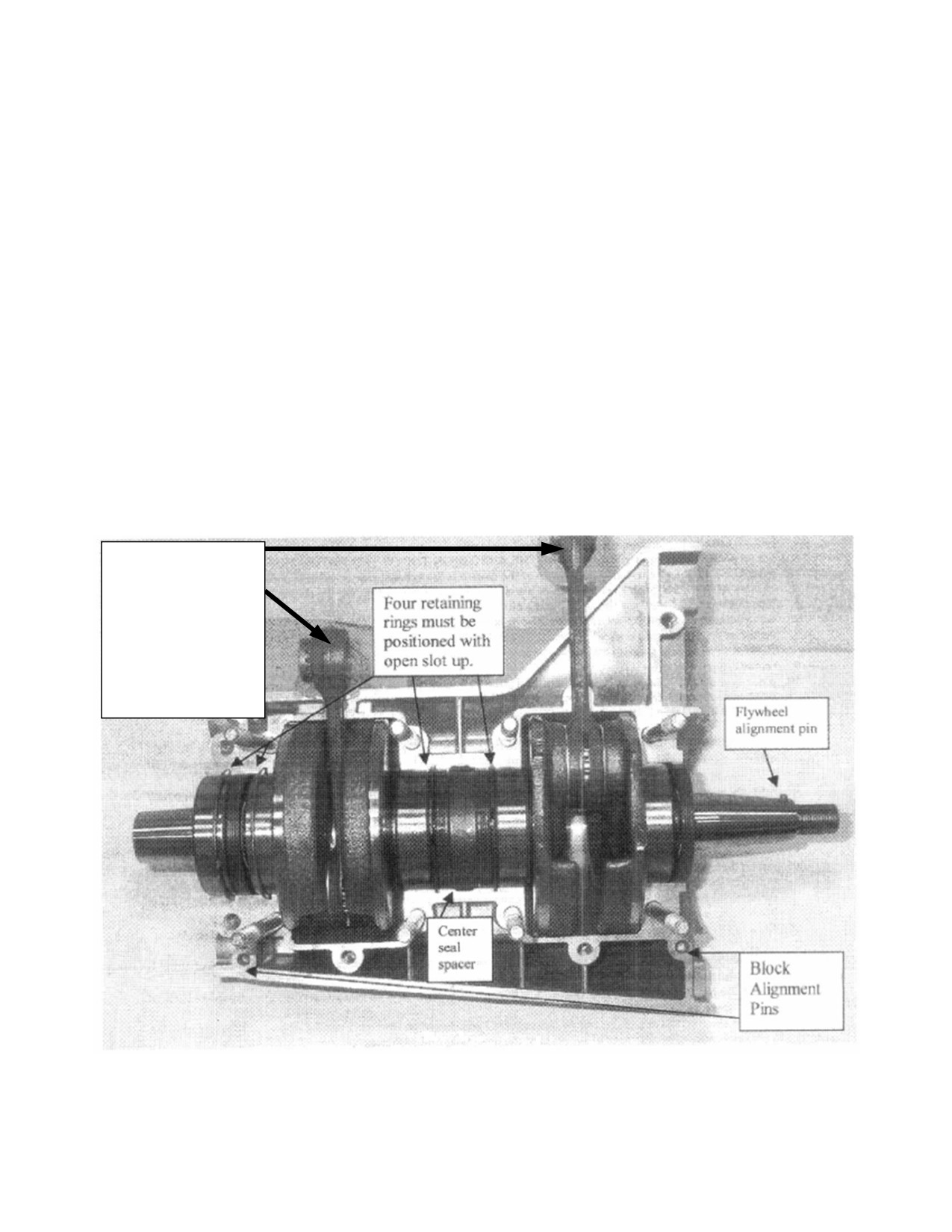
Procedure:
1.
ALL PARTS MUST BE COMPLETELY CLEAN.
2.
Lube all bearings on crankshaft with straight 2 cycle oil.
3.
Place crank in bottom half crankcase, making sure the mag end of the crank is at the correct end of the
crankcase. Tap down slightly to ensure proper seating of bearings, also make sure that all of the
retaining rings are in their correct location and that the split in the retaining ring is up (refer to picture on
this page) and NOT in line with crankcase split. Place center seal spacer in center of crankshaft, bend
separator slightly to ensure a snug fit. Place 2 alignment pins in bottom half of crankcase (they will fit
loose, they are only to fill the void).
4.
You are now ready to place sealant on the top half of the crankcase (only needed on mating surface) a
LIGHT coat of sealant is all that is needed. Use Omni Visc Silicon to seal block halves together.
5.
Now you are ready to assemble the complete bottom end of the engine. Carefully hold the connecting
rods up with one hand and guide them thru the top half of the crankcase as you bring the halves together.
Tap down slightly to ensure proper mating.
6.
Using blue Loctite 242 or 243 on the 7 - 8mm. crankcase bolts, (4 - 6mm and 3 - 8mm bolts on
3202/3203) start all bolts before tightening. Hand tighten using a criss cross torque pattern. With W137
seal setting tool set the mag end seal. Spin crank in crankcase by hand to make sure it is smooth and free
of drag. You are now ready to torque the crankcase bolts to their proper torque setting (228 in/lbs. on
8mm - 96 in/lbs. on 6mm) using once again the criss cross torque, pattern. Spin the crank once again to
ensure smooth operation, and no large increase in drag from the first time spun. If drag increases,
disassemble case and determine cause.
7.
You are now ready to assemble the top end.
Con Rods are
marked with a paint
dot or etched with
a letter to indicate
which needle
bearing is to be
used.
Assy 17333 Form 17334

HOW TO CHANGE FAN OR TIGHTEN FAN BELT
Tools Needed:
•
5mm Allen wrench
•
regular screwdriver
•
7mm wrench (for 2704/06 only)
•
19mm wrench
•
6mm Allen wrench (fan pulley)
Changing Belt Procedure:
1. Remove cover plate or recoil starter
(5mm Allen wrench).
2. Remove fan pulley from flywheel (6mm Allen wrench).
3. Loosen lock nut on fan eccentric cam
shaft (19mm wrench and regular screwdriver).
4. Remove fan tower (you will need to
remove five 6mm bolts to do so using a 5mm Allen
wrench) be careful when doing so because your ign. Wires will still be attached (you
do
not have to remove these wires).
5. Remove fan air deflection plate (2704/06 only) (regular screwdriver and 7mm wrench).
6. Remove fan's eccentric cam shaft (be
careful there may be a spacer washer between
fan case and fan depending
on year of engine).
7. The fan is now free to be removed, replace belt, follow the procedure in reverse.
Notes:
• Do not tighten lock nut until end of procedure.
• Once the fan and belt arc in place, turn eccentric cam to the closest position toward the
fan pulley on flywheel. This will make it easier to install the pulley on flywheel
later and also keep you from over tensioning the belt or stretching the belt.
•
Use blue loctite 242 on fasteners.
• There is no reason to ever remove the plastic fan grill. Removing it will damage the
mounting clips.
Tightening fan belt:
Tools Needed:
- 19mm wrench
- regular screwdriver
- 5mm Allen wrench
Procedure:
1. Remove cover plate or recoil starter
2. With regular screwdriver in one hand and the 19mm wrench
in the other hand, break the nut loose (hold the center shaft
from turning with the screwdriver and break nut free with
wrench) (see illustration).
3. Turn the Screwdriver 10 or 15 degrees to tighten fan belt,
check tension (if the belt does not tension it may be time to
replace it).
4. Hold shaft from turning with screwdriver, tighten nut so that
you cannot turn the shaft when tightened.
5. Reassemble any removed parts.
Form 17328

TIMING
Timing is a term referring to the ignition firing or sparking at a specific time in the crankshaft's cycle of one revolution.
Timing is very important to the proper running of the engine: The engine comes factory timed and should never need
retimed, unless you have changed a flywheel or stator plate or if engine symptoms suggest timing problems.
Tools needed: (to check timing)
•
timing light (without advance preferably)
•
1" indicator and correct sparkplug hole insert to hold indicator
•
pointer (to point at flywheel) (should be stiff enough not to move)
•
5mm Allen wrench to remove cover plate or recoil starter
•
felt marker or paint marker to draw line on flywheel
Procedure:
1.
Remove cover plate or recoil starter with 5mm Allen wrench, and also remove fan pulley with a 6mm Allen
wrench.
2.
Remove one sparkplug from the pto cylinder and remove both sparkplugs from the mag end cylinder (this will
make it much easier to turn the engine over by hand to set up your timing mark)
3.
Place pointer on engine using a bolt you removed to remove the cover plate or recoil starter, put it in a position
that you can easily see the pointer, point it toward the flywheel.
4.
Next, place your dial indicator holder in the mag end sparkplug hole, and then place your 1" dial indicator in the
holder.
5.
Make sure your ignition is turned off.
6.
By hand, turn the flywheel clockwise. You will notice that your dial indicator needle will begin to move when
the piston makes contact. When the needle stops, this is what is known as top dead center, (you must be on the
compression stroke or up stroke of the engine). Hold the flywheel at this point, not allowing it to move either
way and very carefully place a dot on the flywheel at your pointers end. This dot is not your timing mark, it is
just for reference later in the procedure. Also at this time you will want to make note of where your dial
indicator needle stopped and set it for zero by turning the dial face. Go through the steps once again to make
sure you have marked and set your dial indicator correctly. Now it is time to put your timing mark on the
flywheel using the same procedure, your timing mark will come before your TDC mark on the flywheel, how
much before depends on the number of degrees your ignition timing is set for. You should always be on a
compression stroke or up stroke on the crankshaft when setting these marks due to bearing slap.
7.
Now that you have your timing mark on the flywheel properly, you are ready to begin checking the timing.
First, remove your dial indicator from engine and the indicator holder. Second, put all your sparkplugs back in
the holes and torque to spec (engine must be cold to torque sparkplugs or you will risk damaging your heads).
Third, hook up your timing light to the mag end sparkplug wire correctly and whatever power source is
necessary to run your timing light (refer to your timing light owners manual). Next, make sure all your tools,
parts and people are clear of engine, you may want to remove your prop for this procedure for safety reasons, (if
you remove prop, make sure to set your idle setting down or the engine will rev to high), make sure aircraft is
secure so that it will not move if you do leave your prop on, Now you are ready to start the engine and hold at
1700 to 2000 rpm for proper timing, point your timing light toward your pointer and your pointer and timing
mark should line up. If they do not, line up adjustment will be necessary.
IGNITION TIMING SINGLE IGNITION
Degrees
521cc (64mm stroke
625cc (69mm stroke)
55 and 65 HP are 69mm stroke
14
.047”
.052”
All fuel injected timed -18°
16
.061”
.068”
55 HP carbureted - 14°
The above dimensions in inches are the dimensions you use to set the timing mark before top dead center an dial indicator Form 17337
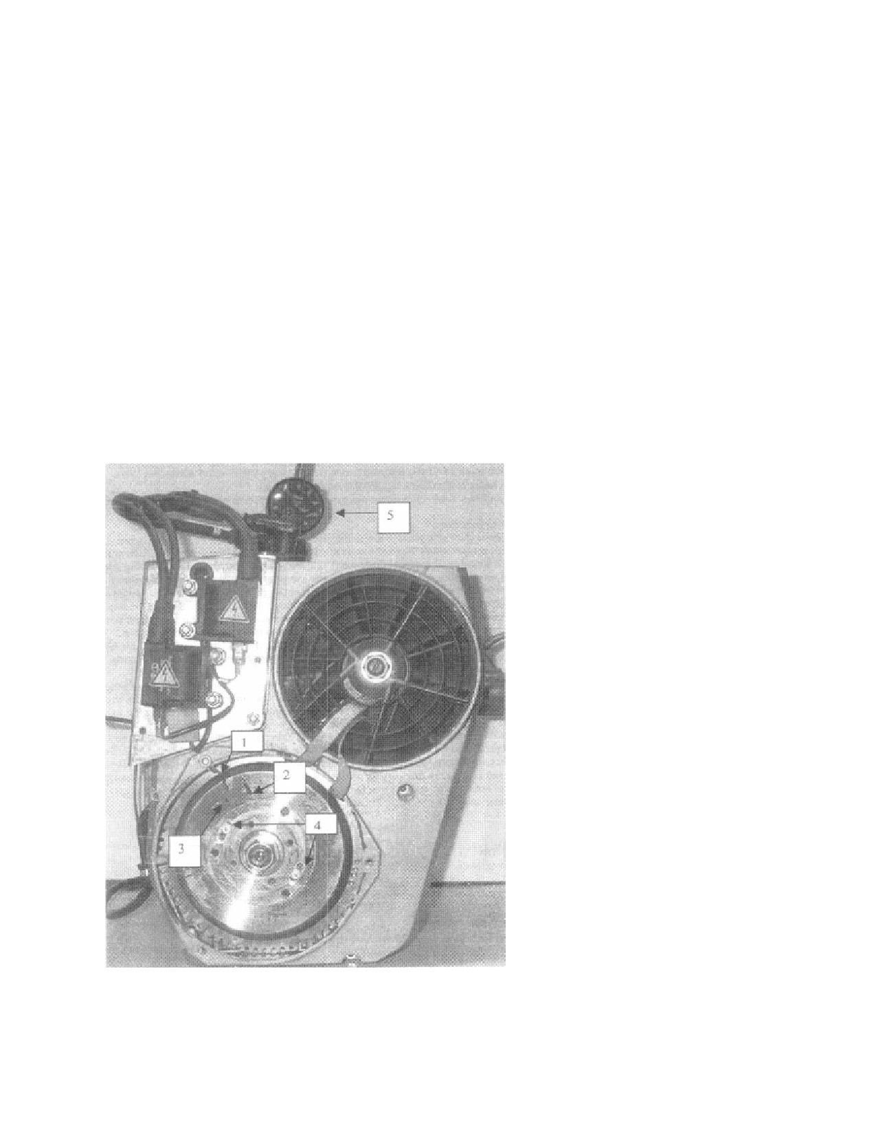
ADJUSTING TIMING PVL
1. Remove cover plate or recoil starter and also fan pulley.
2. To adjust timing you must first loosen 2 small Allen head screws (Item 4) (2.5mm Allen
wrench) at either side of flywheel nut (loosen only slightly).
3. To advance the timing you must turn the screws clockwise, you may do this by slightly
pushing or tapping on loosened screw heads (be careful)..
4. To retard the timing you must turn the screws counter clockwise, you may do this by
slightly pushing, or tapping on the loosened screw heads (be careful).
5. Once the adjustment is made, tighten screws back down and check timing
again (no need
to reset mark or anything). Repeat until correct.
6. Once the timing is set correct check the screw tightness and reassemble any removed
parts (fan pulley, recoil starter, or cover plate, etc.)
1.
Temporary timing pointer
installed.
2.
Timing mark
(for degrees
before top dead center, this
mark will line
up with pointer,
when shooting with timing
light, when the timing is
adjusted correctly).
3.
Top dead center mark (for
reference).
4.
PVL timing adjustment
screws (turned
clockwise to
advance timing, turned
counter clockwise to retard
timing).
5.
Dial indicator
installed in
sparkplug hole for timing
mark set up.
Form 17338

TABLE OF TORQUE VALUES 100 HP ENGINE
TORQUE
Fastener Descriptions
si·ze
IDCh lb.
CYLINDER HEAD SCREWS
8mm
228 inch Lbs.
OUTER MAGNETO RING
6mm
72inch Lbs.
INTAKE MANIFOLD MOUNTING SCREWS
6mm
84inch Lbs.
CRANKCASE ASSEMBLY SCREWS
6mm
84inch Lbs.
V BELT PULLEY MOUNTING SCREWS
6mm
84 inch Lbs.
ELECTRIC STARTER MOUNTING SCREWS
8mm
228 inch Lbs.
CYLINDER BASE NUTS
8mm
228 inch Lbs.
EXHAUST MANIFOLD MOUNTING SCREWS
8mm
228 inch Lbs.
RUBBER INTAKE FLANGE SCREWS
6mm
84 inch Lbs.
SPARK PLUGS
14mm
192 inch Lbs.
CRANKSHAFT BOLT (PTO-end)
(Yz inch NF)
Yz" NF
552 inch Lbs.
CRANKSHAFT NUT(Ma2neto end)
16mm
107 FT Lbs.
ENGINE MOUNTING BOLTS
lO mm
444 inch Lbs.
COOLANT MANIFOLD BOLTS
6 mm
84 inch Lbs.
100 HP ENGINE TECHNICAL DATA
Engine
lOOHp
I2n.Timin2@2000 - carbureted
18 de2.
I2n.Timin2t@2000 - Fuel injected
18 de2.
Spark Plu2 Heat VI.
280
Spark Plu2 Gap
.030
No. of Carburetors/lniectors
Three
Carburetor ID #
Dellorto - PHB34
Main Jet
165
Needle Jet
AB 265
Needle
K 43
Idle Jet
50
Do Not Exceed RPM
6300
Peak HP RPM
6000
HP @ Peak RPM
100
Peak Torque RPM
5500
Peak Torque Ft.Lb.
88
Maximum CHT
390
Maximum EGT (ti) full power
1256
Maximum EGT @ cruise power
1330
Maximum coolant temperature
240
Minimum coolant temperature
160
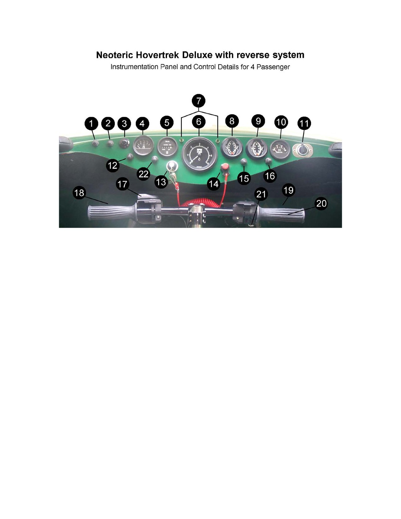
(Part #’s)
1.
Headlight Switch (1652)
2.
Navigation & Instrument Light Switch (1652)
3.
Horn Button (2443)
4.
Gasoline/Petrol Gauge (1628)
5.
Hour Meter (6148)
6.
Tachometer (5351)
7.
Reverse Thrust Diagnostic Lights (5633)
8.
Engine 2 Cylinder Head Temperature (5326)
9.
Engine 2 Exhaust Gas Temperature (5327)
10.
Volt Meter (5817)
11.
12 Volt Supply Cigarette Plug (5688)
12.
Bilge Pump (1652)
13.
Ignition Switch (1884)
14.
Kill Switch (1052)
15.
Reverse Thrust On Off Switch (1652)
16.
Reverse Thrust Reset Switch (2431)
17.
Choke Lever (7348)
18.
Port Reverse Thrust Control Lever (7369)
19.
Starboard Reverse Thrust Control Lever (7369)
20.
Throttle Grip (6617)
21.
Throttle Cruise Control Lock Screw or Lever (7444)
22.
Electric Fuel Pump (1652)
Form 17481
23.
Lanyard Cord (1090)
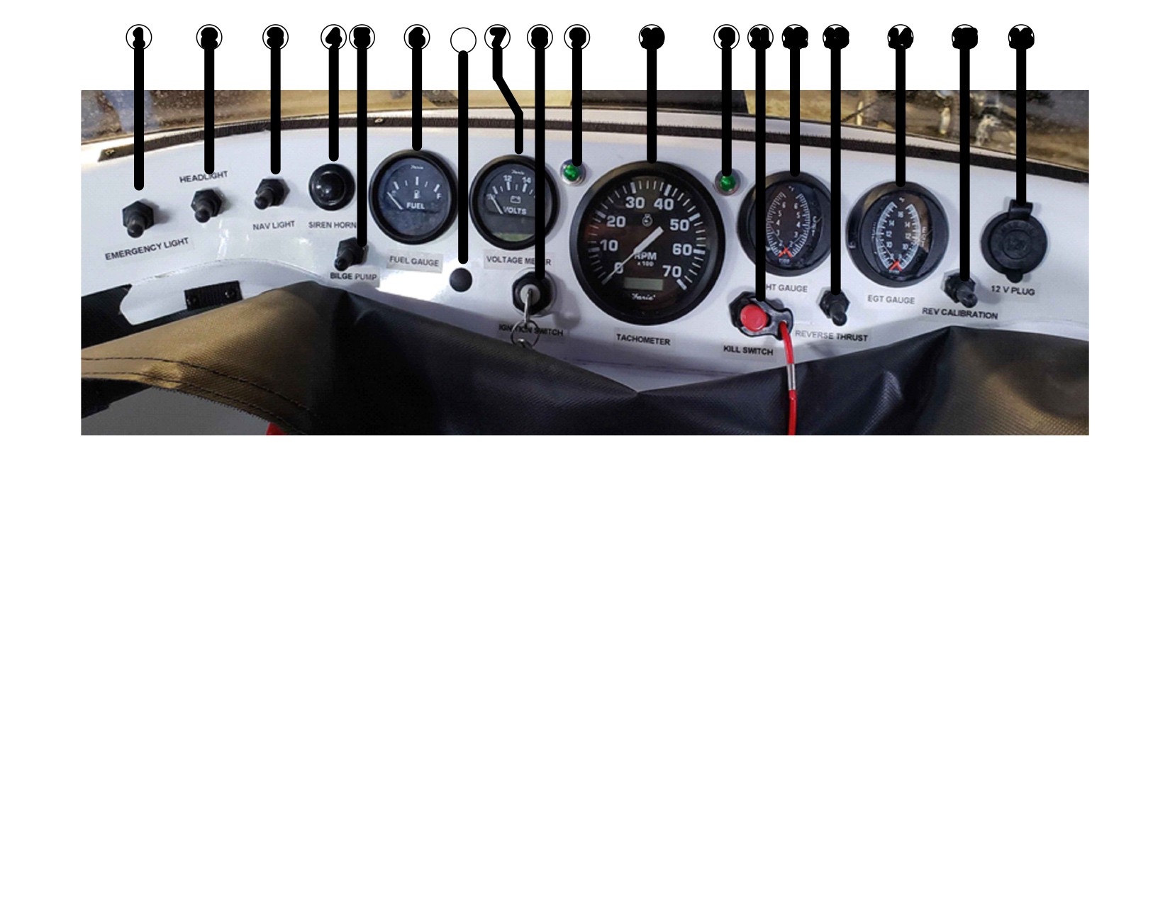
17
(Part #’s)
1.Emergency Light Switch (1652)
2.Headlight Switch (1652)
3.Navigation & Instrument Light Switch (1652)
4. Horn Button (2443)
5. Bilge Pump Switch (1652)
6. Gasoline/Petrol Gauge (1628)
7. Volt Meter (5817)
8. Ignition Switch (1884)
9. Reverse Thrust Diagnostic Lights (5633)
10. Tachometer W/ hour meter (5351)
11. Kill Switch (1052)
12. Engine 2 Cylinder Head Temperature (5326) (CHT)
13. Reverse Thrust On Off Switch (1652)
14. Engine 2 Exhaust Gas Temperature (5327) (EGT)
15. Reverse Thrust Reset Switch (2431)
16. 12 Volt Supply Cigarette Plug (5688)
17. Electric Fuel Pump Switch (1652) (Fuel Injection Only) Plastic Plug (2449)
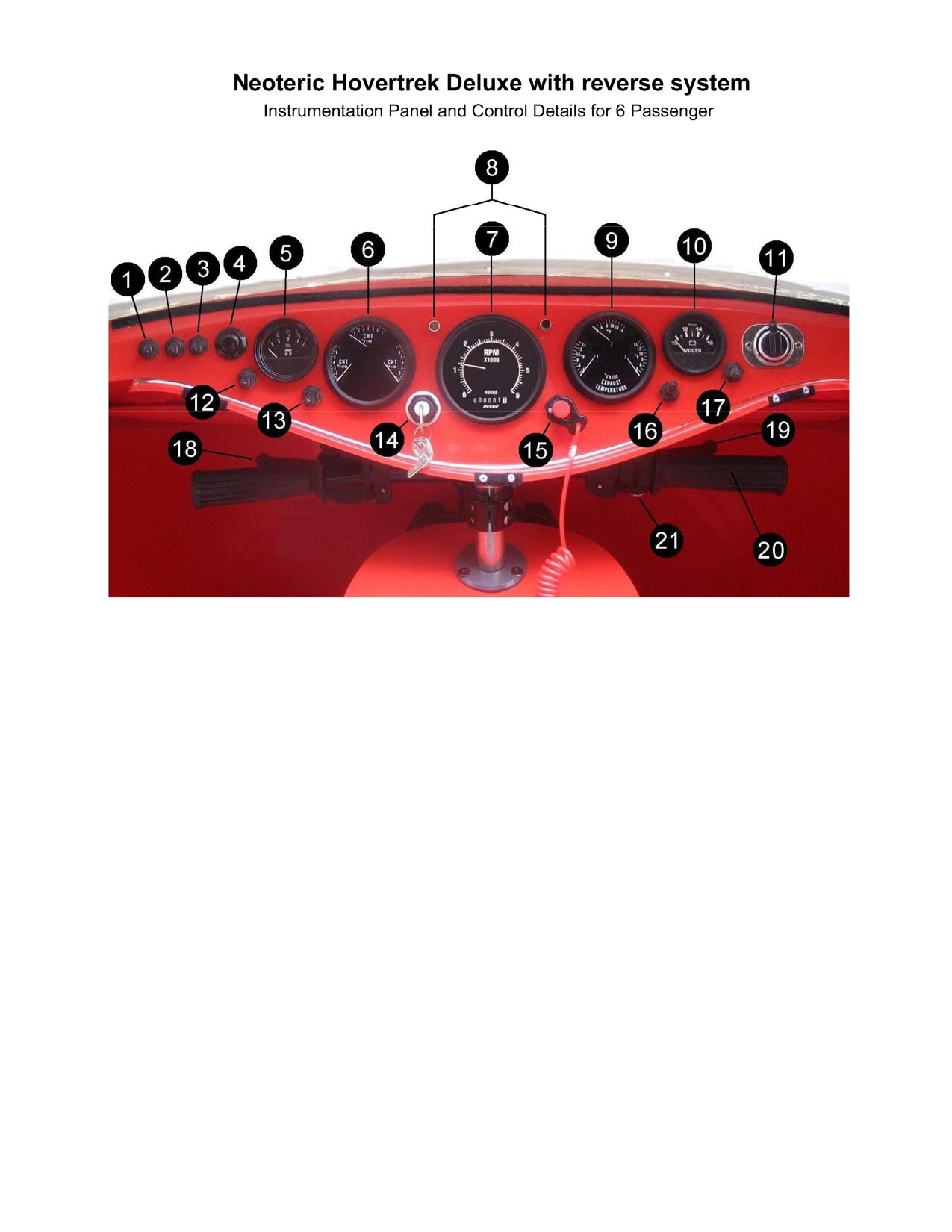
1.
Strobe Emergency Light (1652)
2.
Headlights (1652)
3.
Navigation & Instrument Light Switch (1652)
4.
Horn/Siren Button (2443)
5.
Gasoline/Petrol Gauge (1628)
6.
Engine Cylinder Head Temperature or Water Temperature, depending on
gauge type (water temp gage 6166)
7.
Tachometer and hour meter (5350)
8.
Reverse Thrust Diagnostic Lights (5633)
9.
Engine Exhaust Gas Temperature (5647)
10.
Volt Meter (5817)
11.
12 Volt Supply Cigarette Plug (5688)
12.
Bilge Pump (1652)
13.
Electric Fuel Pump (1652)
14.
Ignition Switch (1884)
15.
Kill Switch (1052)
16.
Reverse Thrust On Off Switch (1652)
17.
Reverse Thrust Reset Switch for Calibration (2431)
18.
Port Reverse Thrust Control Lever (7369)
19.
Starboard Reverse Thrust Control Lever (7369)
20.
Throttle Grip (6617)
21.
Throttle Cruise Control Lock Screw or Lever (7444)
Form 17482
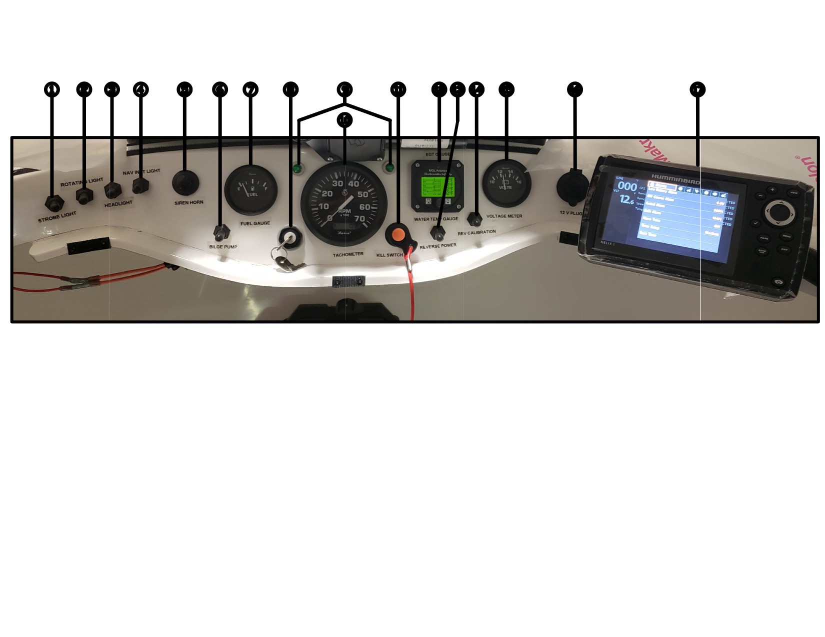
1) Strobe Light Switch (1652)
2) Rotating Light Switch (1652)
3) Headlight Switch (1652)
4) Nav Light Switch (1652)
5) Horn Button (2443)
6) Bilge Pump Switch (1652)
7) Fuel Gauge (1628)
8) Ignition Switch (1884)
9) LED Reverse Diagnostic Lights (5633)
10) Tachometer W/ Hour Meter (5351)
11) Kill Switch (1052)
12) EGT and Water Temp Gauge (9285)
13) Reverse Power Switch (1652)
14) Reverse Reset, Momentary Switch (2431)
15) Volt Meter Gauge (5817)
16) 12V Power Supply (5688)
17) GPS Options Helix 5 (9482) Garmin (9065)
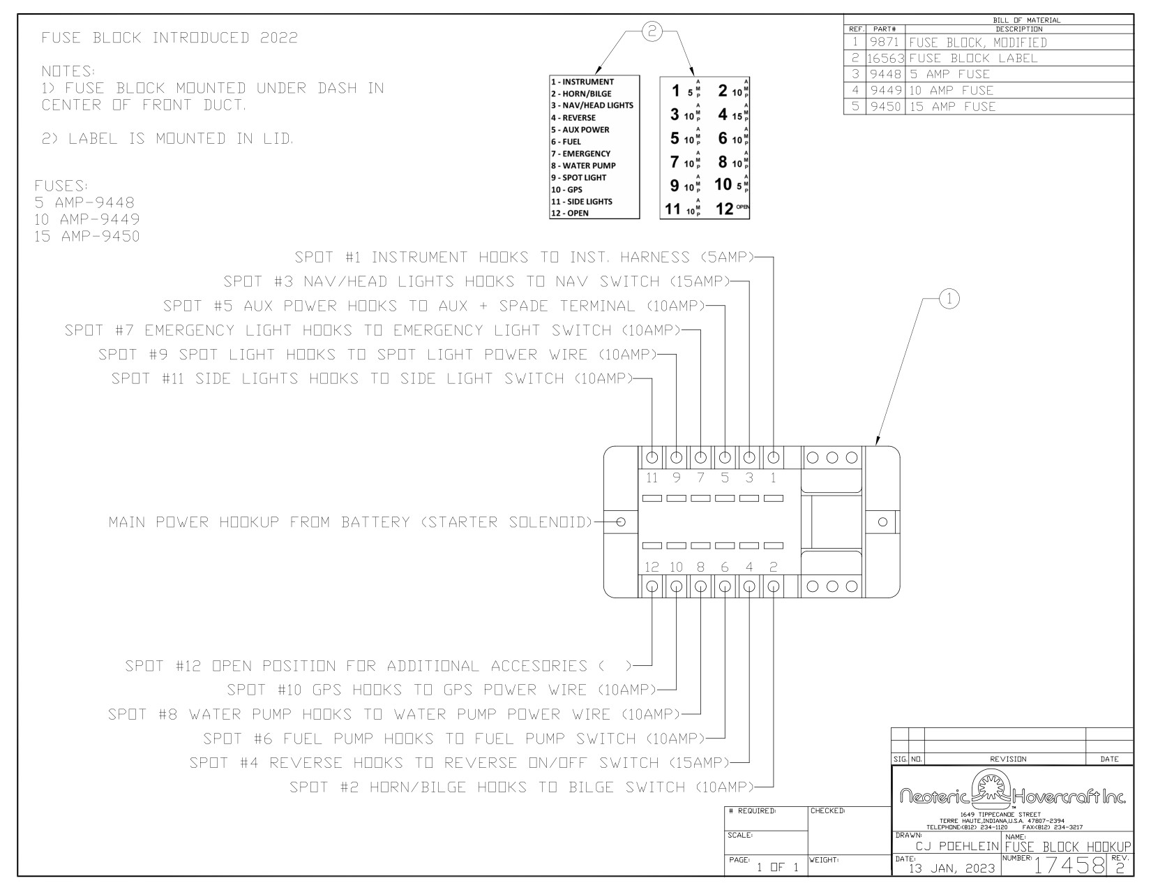
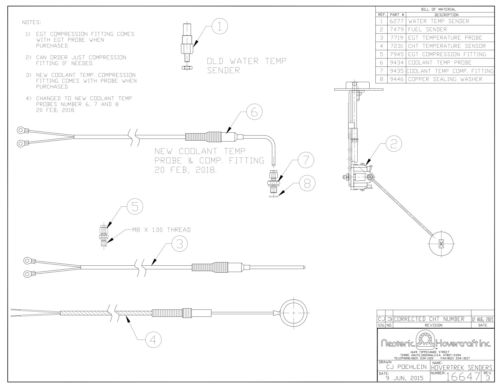
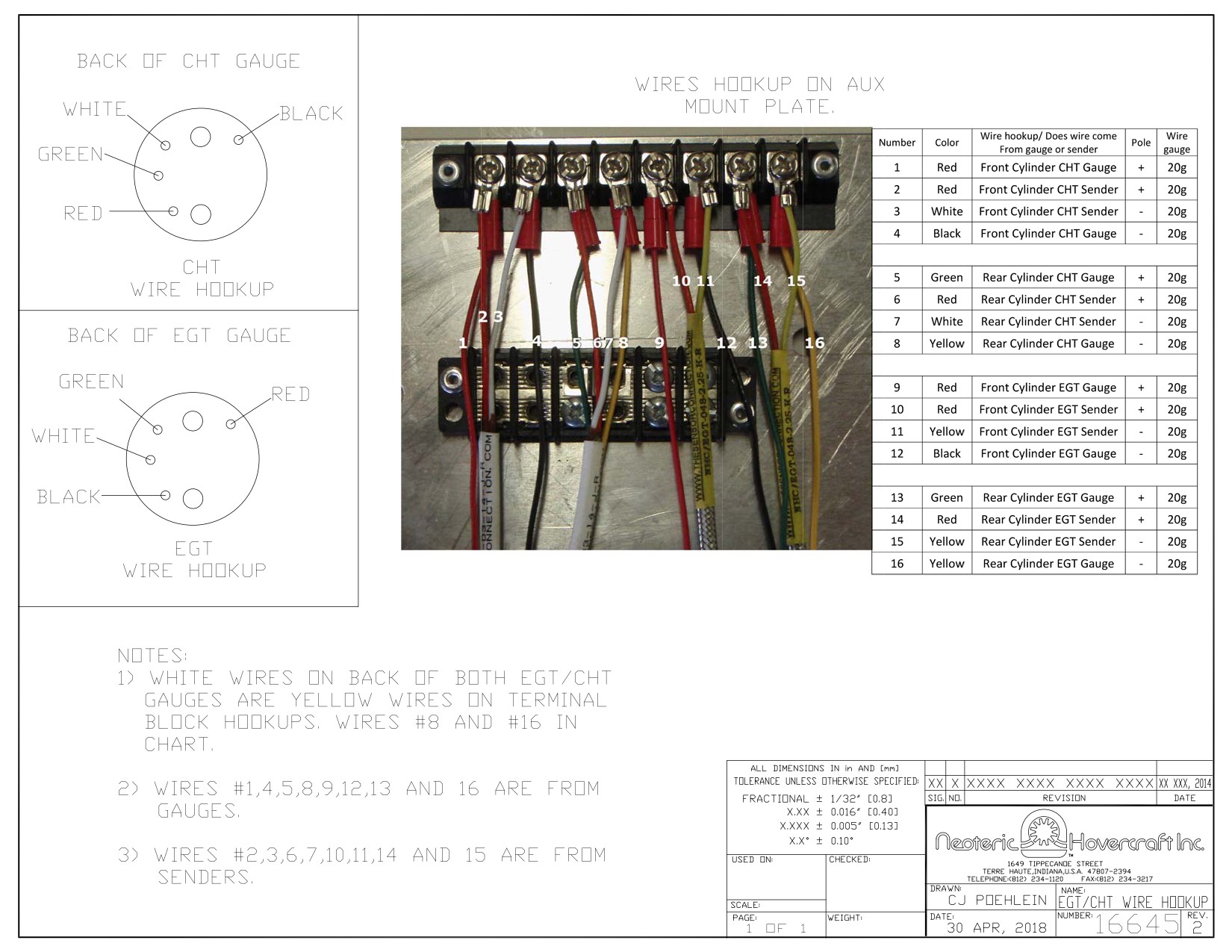

Instructions for configuring the EGT & Water Temperature Gauge, Matt Rose, 25 July 2018
MGL Avionics instrument, TC1 Gauge
Note:
A. Top scale is chart scaling: do not use this
B. Set point is the alarm point when the red warning light flashes
C. Span in the rage of the bar graph it's the difference between highest and lowest temp
D. Alarm also goes off at set point
E. Span is set above the alarm set point
F. Knob can be used to do the same things as the Up and Down arrows F1 and F2
Procedure
1. Turn instrument on
2. Press center knob. Screen will read Exit Menu
3. Press the DOWN arrow F2 and screen will show DISPLAY SETUP
4. Press the DOWN arrow F2 and screen will show TC Setup
5. Press center knob
6. Adjust display contrast by turning knob to indicate approximately 2/3 thirds
7. Press center knob
8. Press DOWN arrow F2 to highlight BACKLIGHT
9. Press and turn center knob to select ON
10. Press center knob to select
11. Press DOWN arrow F2 to highlight Display
12. Press center knob to select Multi/Horizontal
13. Press center knob to select
14. Press UP arrow F1 and press center knob to select DONE
15. Press DOWN arrow F2 to highlight TC SETUP
16. Press center knob
17. Press DOWN arrow F2 to select TC CHANNELS
18. Set to 4 which is the number of thermocouples being used
19. Press center knob to select 4
20. Press DOWN arrow F2 to TEMP UNIT
21. Press center knob
22. Turn center knob to indicate degree F or degree C (Fahrenheit or Celsius)
23. Press center knob to select
Note: Channel configuration only applies to Multiple Horizontal bar display as selected in DISPLAY SETUP
This process is used for configuring CH1, CH2, CH3 and CH4 SETUPS
1. Press DOWN arrow F2 to select CH 1 SETUP
2. Press center knob to enter channel configuration menu
3. Press DOWN arrow F1 to highlight SPAN
4. Press center knob to change parameter

5. Turn center knob to select the value given in the configuration table shown at the end
6. Press center knob to select
7. Press DOWN arrow F1 to highlight TOPSCALE
8. Press center knob to change parameter
9. Press center knob and turn to select ON
10. Press center knob to select
11.
Press DOWN arrow F2 to highlight SETPOINT
12. Press center knob to change parameter
13.
Turn center knob to value indicated in the configuration table shown at the end
14.
Press center knob to select
15.
Press DOWN arrow F2 to highlight ALARM ON or OFF
16.
Press center knob to change parameter
17.
Turn center knob to value indicated in the configuration table shown at the end
18.
Press center knob to select
19.
Press DOWN arrow F2 to highlight PROBE
20.
Press center knob to change parameter
21.
Turn center knob to value indicated in the configuration table shown at the end
22.
Press center knob to select
23.
Press center knob to change parameter
24.
Press DOWN arrow F2to highlight LABEL
25.
Press center knob to select parameter
26.
Turn center knob to value indicated in the configuration table shown at the end
27.
Press center knob to select
28.
Press center knob to change parameter
29.
Press UP arrow F1 multiple times until DONE shows
30.
Press UP arrow F1 to DONE and press center knob, TC SET UP will show
31.
Press UP arrow F1 to DISPLAY SETUP and press center knob

MGL AVIONICS Instrument TC1 Gauge Configuration
HT6 configuration Table for HT6 craft
EGTs
DISPLAY SETUP
Parameter
Setting
Backlight
ON
Disp
MULT/HORI
Contrast
2/3
TC SETUP
TC Channels
3
Temp Unit
F
Channel 1, 2 and 3. See TC SETUP
Span
1650
Setpoint
1380
Alarm ON/OFF
ON
Probe
K type
Label
EGT 1, EGT 2, EGT 3

MGL AVIONICS Instrument TC1 Gauge Configuration
Configuration Table for HT6 Craft
Water Temp
DISPLAY SETUP
Parameter
Setting
Backlight
ON
Disp
MULT/HORI
Contrast
2/3
TC SETUP
TC Channels
4
Temp Unit
F
Channel 4, See TC SETUP
Top Scale O N
Span
250
Setpoint
210
TOPSCALE
ON
Alarm ON/OFF
ON
Probe
J type
Label
H20T
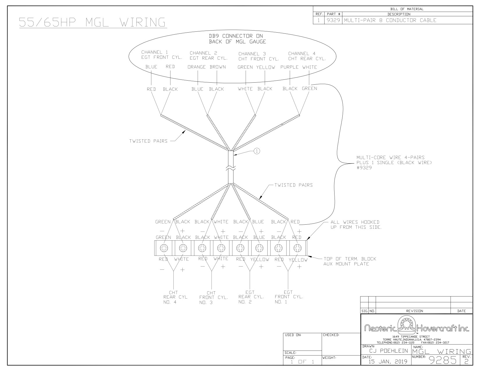
EGT READS FIRST
ON GAUGE