Saf-T-Liner C2 School Bus Chassis. Owner’s Manual
Foreword
at any time without notice and without incurring obliga-
Introduction
tion. Descriptions and specifications contained in this
This manual provides information needed to operate
publication provide no warranty, expressed or implied,
and understand the school bus chassis and its compo-
and are subject to revisions and editions without notice.
nents. More detailed information is contained in the
Owner’s Warranty Information for North America book-
Environmental Concerns and
let, and in the vehicle’s workshop and maintenance
manuals.
Recommendations
Freightliner chassis are equipped with various chassis
Whenever you see instructions in this manual to discard
and cab components. Not all of the information con-
materials, you should first attempt to reclaim and re-
tained in this manual applies to every vehicle. If parts
cycle them. To preserve our environment, follow appro-
on your chassis differ from those shown, they may have
priate environmental rules and regulations when dispos-
been installed by the vehicle manufacturer; if so, ser-
ing of materials.
vice part responsibility belongs to the vehicle manufac-
turer.
Event Data Recorder
The safety or performance of your vehicle could be ad-
versely affected by the installation of nonstandard com-
This vehicle is equipped with one or more devices that
record specific vehicle data. The type and amount of
ponents. Note the limitations and specifications pro-
vided in the vehicle and chassis manuals, and consult
data recorded varies depending on how the vehicle is
equipped (such as the brand of engine, if an air bag is
your selling dealer before making any alterations to the
vehicle or chassis.
installed, or if the vehicle features a collision avoidance
system, etc.).
For your reference, keep this manual in the vehicle at
all times.
Customer Assistance Center
IMPORTANT: Descriptions and specifications in this
manual were in effect at the time of printing. Freightliner
Having trouble finding service? Call the Customer As-
Custom Chassis Corporation reserves the right to dis-
sistance Center at 1-800-385-4357 or 1-800-FTL-
continue models and to change specifications or design
HELP. Call night or day, weekdays or weekends, for
STI-346 (8/05P)
Printed in U.S.A.
Foreword
dealer referral, vehicle information, or breakdown coor-
1-800-424-9153); go to http://www.safercar.gov; or
dination. Our people are knowledgeable, professional,
write to: Administrator, NHTSA, 400 Seventh
and committed to keeping your vehicle moving.
Street, SW, Washington, DC 20590. You can also
obtain other information about motor vehicle safety
Reporting Safety Defects
from http://www.safercar.gov.
If you believe that your vehicle has a defect which
Canadian customers who wish to report a safety-
could cause a crash or could cause injury or
related defect to Transport Canada, Defect Investi-
death, you should immediately inform the National
gations and Recalls, may telephone the toll-free
Highway Traffic Safety Administration (NHTSA) in
hotline 1-800-333-0510, or contact Transport
addition to notifying Freightliner Custom Chassis
Canada by mail at: Transport Canada, ASFAD,
Corporation.
Place de Ville Tower C, 330 Sparks Street,
Ottawa, Ontario, Canada K1A 0N5.
If the NHTSA receives similar complaints, it may
open an investigation, and if it finds that a safety
For additional road safety information, please visit
defect exists in a group of vehicles, it may order a
the Road Safety website at: http://www.tc.gc.ca/
recall and remedy campaign. However, NHTSA
roadsafety/menu.htm
cannot become involved in individual problems
between you, your dealer, or Freightliner Custom
Chassis Corporation.
To contact NHTSA, you may call the Vehicle
Safety Hotline toll-free at 1-888-327-4236 (TTY:
No part of this publication, in whole or part, may be translated, reproduced, stored in a retrieval system, or transmitted
in any form by any means, electronic, mechanical, photocopying, recording, or otherwise, without the prior written per-
mission of Freightliner LLC. For additional information, please contact Freightliner LLC, Service Systems and Docu-
mentation, P.O. Box 3849, Portland OR 97208-3849 U.S.A. or refer to http://www.Freightliner.com and http://www.
FreightlinerChassis.com.
Contents
Chapter
Page
Introduction, Environmental Concerns and Recommendations, Event
Data Recorder, Customer Assistance Center, Reporting Safety Defects
Foreword
1
Vehicle Identification
1.1
2
Driver Controls and Instruments
2.1
3
Engines
3.1
4
Clutches
4.1
5
Transmissions
5.1
6
Steering System
6.1
7
Brake System
7.1
8
Pretrip Inspection and Daily Maintenance
8.1
9
In an Emergency
9.1
10
Specifications
10.1
Index
I.1
1
Vehicle Identification
Vehicle Specification Label
1.1
Federal Motor Vehicle Safety Standard (FMVSS) Labels
1.1
Vehicle Identification Number (VIN)
1.1
Vehicle Identification
Vehicle Specification Label
Vehicle Identification Number
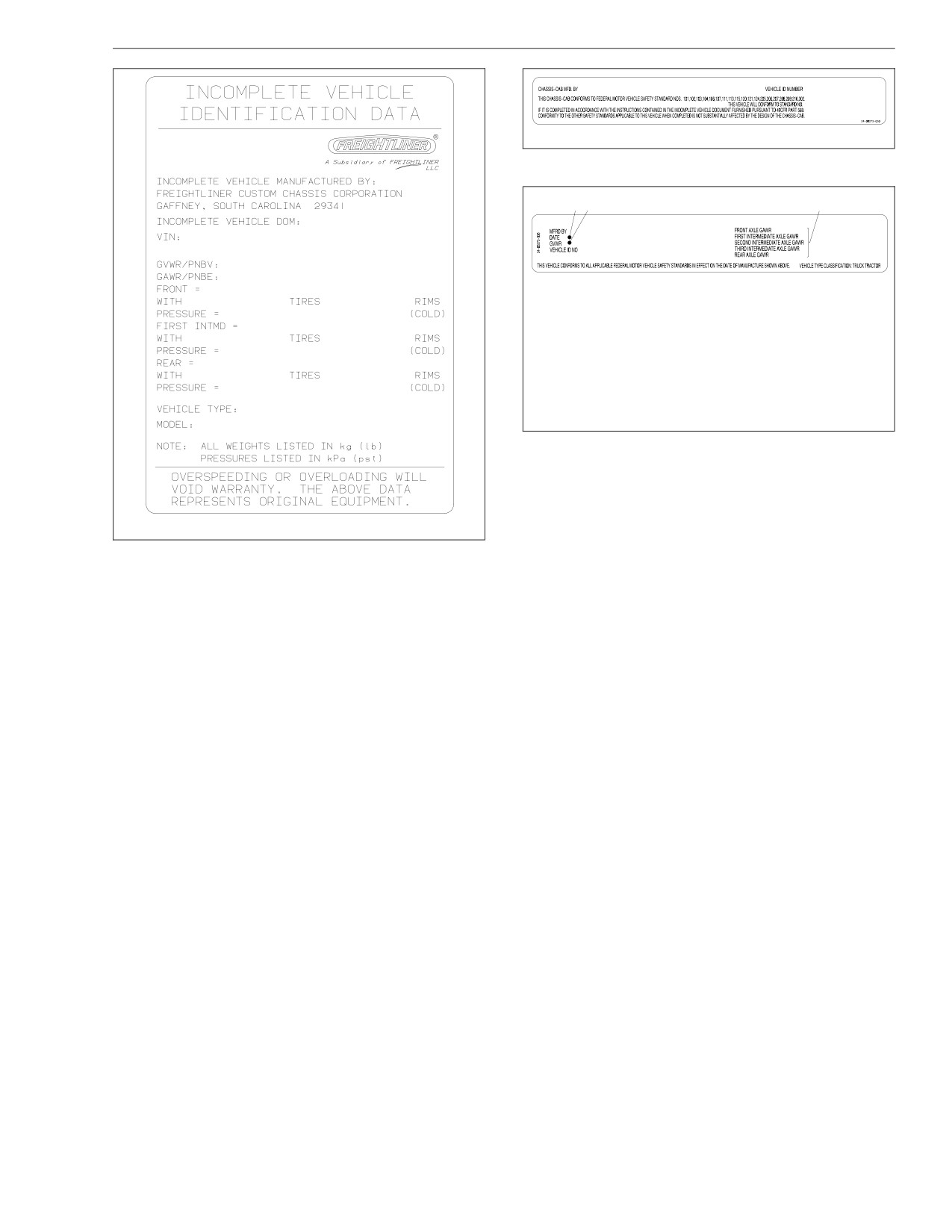
The vehicle specification label lists the vehicle model,
(VIN)
identification number, and major component models. It
The chassis vehicle identification number (VIN) is per-
also recaps the major assemblies and installations
manently attached to the chassis. See Fig. 1.4.
shown on the chassis specification sheet. See Fig. 1.1.
NOTE: Always include the chassis serial number
NOTE: Labels shown in this chapter are examples
(last six digits of the VIN) when communicating
only. Actual specifications may vary from vehicle to
with Freightliner Custom Chassis Corporation.
vehicle.
Federal Motor Vehicle Safety
Standard (FMVSS) Labels
If purchased for service in the U.S., chassis built with-
out a body have a certification label similar to that
shown in Fig. 1.2. In addition, after completion of the
vehicle, a certification label similar to that shown in
Fig. 1.3 must be attached by the final-stage manufac-
turer. This label certifies that the vehicle conforms to all
applicable FMVSS regulations in effect on the date of
completion.
NOTE: On incomplete vehicles, it is the responsi-
bility of the final-stage manufacturer to complete
the vehicle and label it for compliance.
1.1
Vehicle Identification
09/28/98
f080023
Fig. 1.2, Incomplete Vehicle Certification Label, U.S.
1 2
3
11/21/96
f080053
1. Date of Manufacture: by month and year
2. Gross Vehicle Weight Rating: developed by taking
the sum of all the vehicle’s gross axle ratings
3. Gross Axle Weight Ratings: developed by
considering each component in an axle system—
including suspension, axle, wheels, and tires—and
using the lowest component capacity as the value
for the system
Fig. 1.3, Certification Label, U.S.
09/11/2002
f080123
Fig. 1.1, Vehicle Specification Label
1.2

Vehicle Identification
12/04/2001
f080122
Fig. 1.4, Vehicle Identification Number (VIN) Label, Typical
1.3
2
Driver Controls and Instruments
Instrument and Control Panel
2.1
Controls
2.1
Warning and Indicator Lights
2.8
Instruments
2.10
Instrumentation Control Unit, Level III
2.15
Hood Tilting
2.32
Driver Controls and Instruments
In the ON position (key turned 45 degrees clockwise),
Instrument and Control Panel
all of the electrical systems are operable. Warning lights
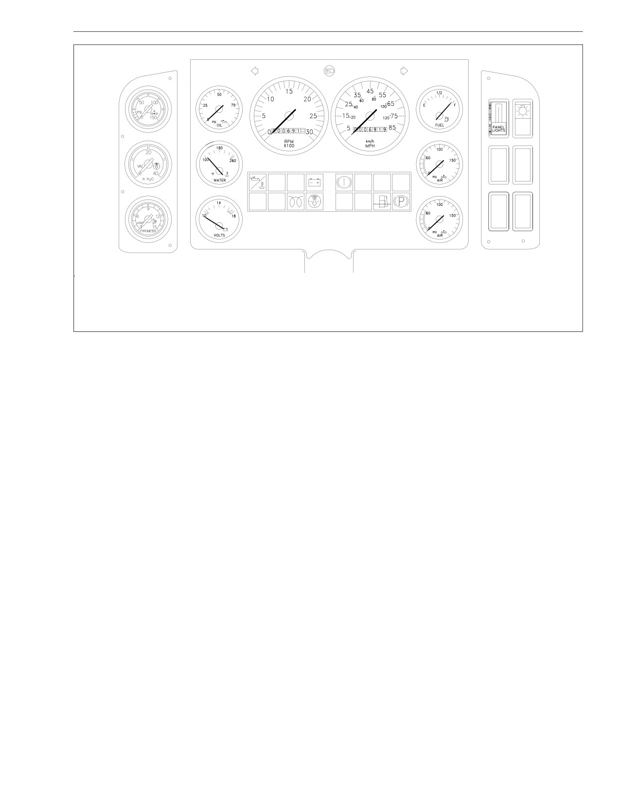
Figure 2.1 represents a typical Freightliner dash
and the buzzer for low air pressure (if equipped with air
equipped with all of the standard and many of the op-
brakes) and low oil pressure operate until the engine is
tional instruments and controls.
started and minimum pressures build up.
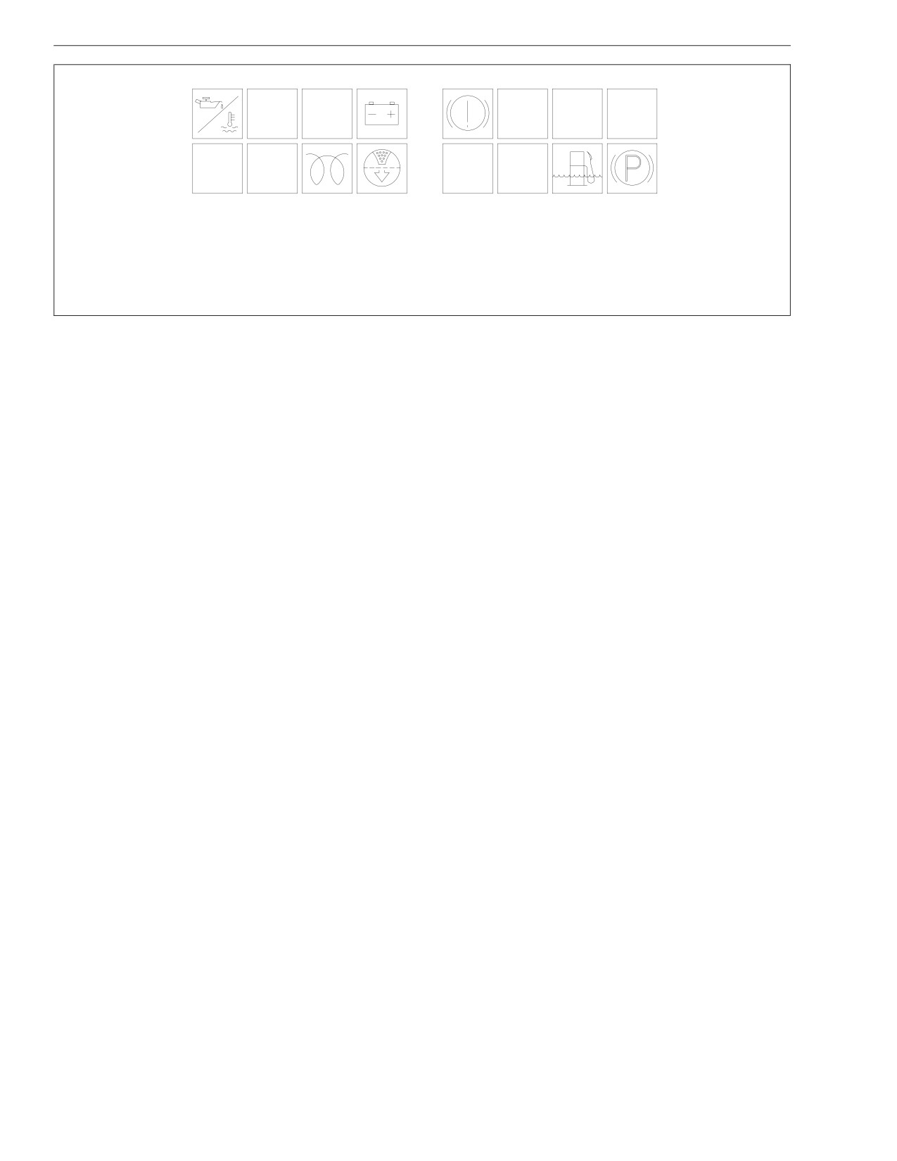
A warning and indicator light module, located below the
Panel Light Control Lever
speedometer and tachometer, houses all of the stan-
dard and optional warning and indicator lights. Figure
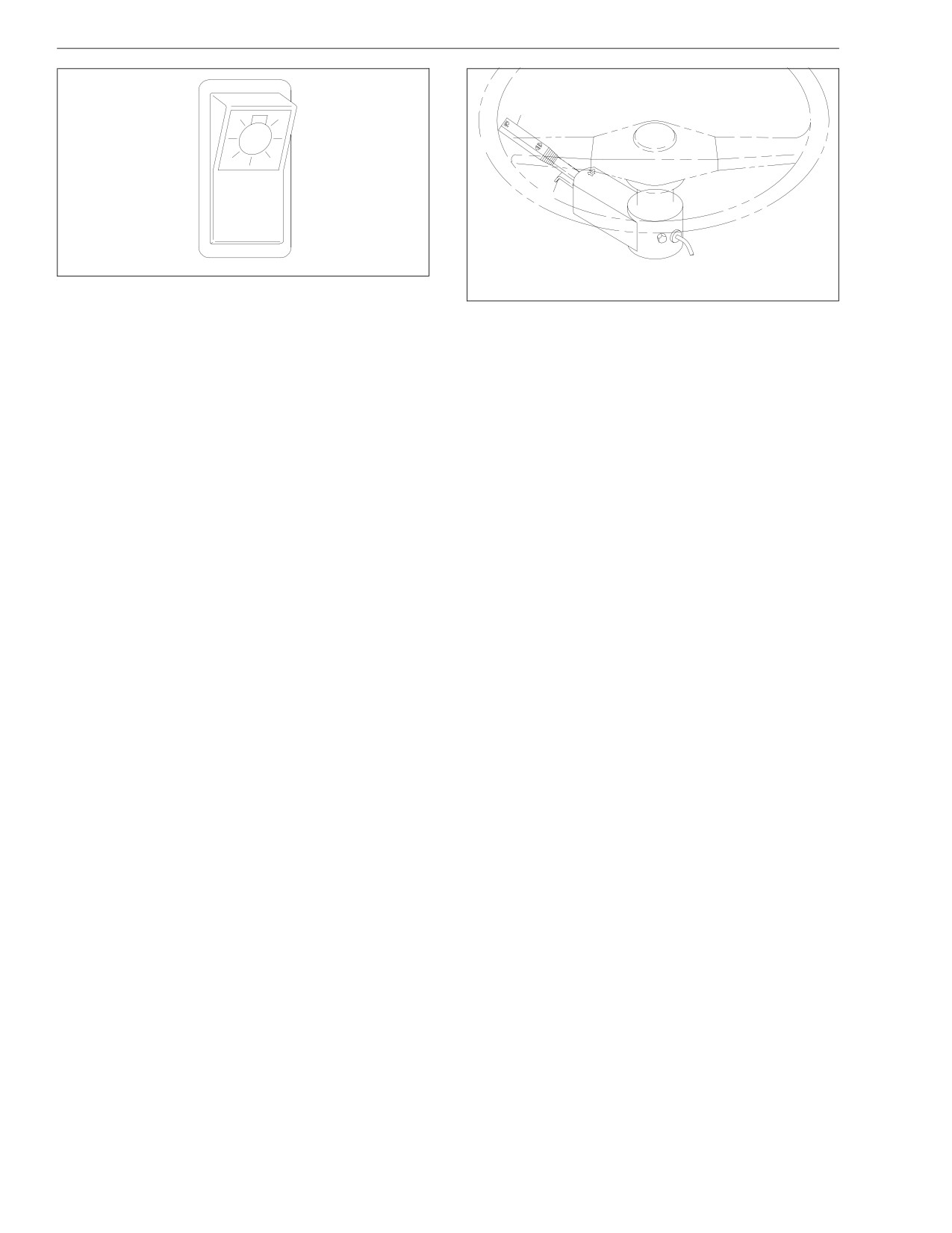
Turn on the panel lights with the headlight switch. The
2.2 identifies the warning and indicator lights.
panel light lever controls the brightness of the instru-
ment panel lights. Slide the control lever up to brighten
the lights, and down to dim them. Move the control le-
Controls
ver all the way down to turn them off. See Fig. 2.4.
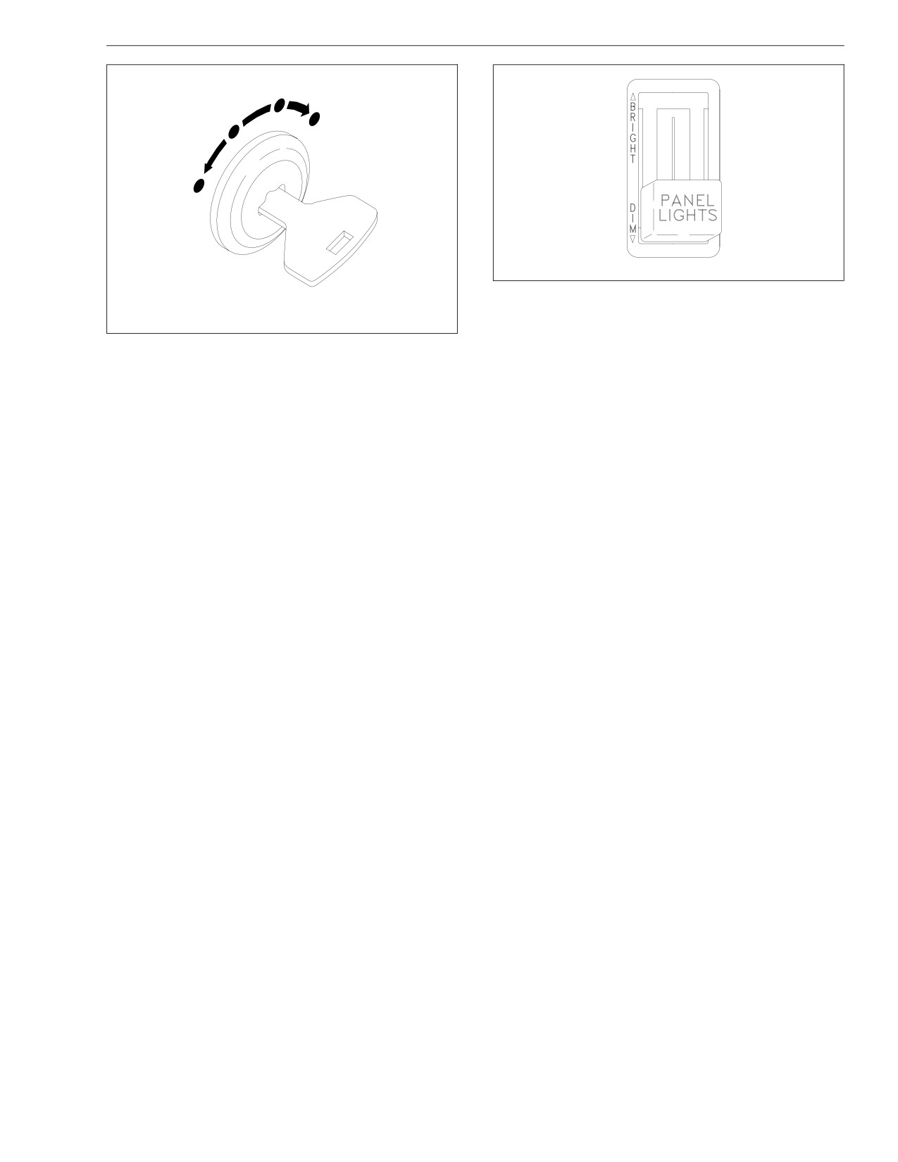
Ignition Switch and Key
Headlight Switch and Daytime
The ignition switch can be turned to four positions: AC-
CESSORY, OFF, ON, and START. See Fig. 2.3.
Running Lights
The key can be inserted and removed only from the
In the down position all lights are off. Move the switch
OFF position. The headlights (low beams only), fog
to the middle position to turn on the parking lights.
lights, turn signals, hazard warning lights, and the park-
Move the switch to the up position to turn on the head-
ing lights operate with the ignition switch in the OFF
lights. See Fig. 2.5.
position, regardless of whether the key is inserted.
For vehicles built to operate in Canada, turn the ignition
In the accessory (ACC) position (key is turned counter-
switch to the ON position and release the parking brake
clockwise), all of the electric gauges operate.
to automatically activate the low-beam headlights (later
model vehicles) at half voltage as daytime running
Turn the key fully clockwise to the START position only
lights. The daytime running lights operate until the park-
when starting the engine. When the engine starts, re-
ing brake is applied, and then will switch off. Turning on
lease the key. When released, the key will rotate coun-
the regular headlights overrides the daytime running
terclockwise to the ON position.
2.1
Driver Controls and Instruments
7
8
9
1
6
13
14
2
10
5
LOW
OIL
ABS
3
ENG
ENG
DO NOT
TRANS
DOWN
CHK
SHIFT
TEMP
12
4
11
09/12/96
f601174
1. Application Air Pressure Gauge
6. Engine Oil Pressure Gauge
11. Secondary Air Pressure Gauge
2. Air Restriction Gauge
7. Tachometer
12. Warning and Indicator Light
3. Pyrometer
8. Speedometer
Module
4. Voltmeter
9. Fuel Gauge
13. Panel Light Control Lever
5. Water Temperature Gauge
10. Primary Air Pressure Gauge
14. Headlight Switch
Fig. 2.1, Instrument and Control Panel Layout
2.2
Driver Controls and Instruments
1
2
3
4
5
LOW
ABS
OIL
ENG
ENG
DO NOT
TRANS
DOWN
CHK
SHIFT
TEMP
6
7
8
9
10
11
12
13
09/12/96
f601175
1. Low Oil Pressure/High Water
6. Stop Engine Indicator
11. High Oil Temperature Warning
Temperature Warning
7. Engine Check Indicator
(automatic transmission)
2. Low Oil Level Warning
8. Cold-Start Manifold Heater
12. Water in Fuel/Water Separator
3. Alternator Warning Light
Indicator
Warning
4. Brake System Warning
9. Air Cleaner Restriction Indicator
13. Parking Brake Indicator Light
5. ABS Warning Light
10. Do Not Shift Indicator
Fig. 2.2, Warning and Indicator Lights
lights. The vehicle cannot be driven unless either the
Turning the knob counterclockwise decreases the effort
headlights or the daytime running lights are activated.
needed to move the lever.
If the parking brake does not hold the vehicle securely,
Parking Brake Control Lever
depress the brake pedal and release the parking brake.
Turn the knob on the end of the lever clockwise to in-
Vehicles With Hydraulic Brakes
crease the parking brake application.
A parking brake control lever is located to the left of the
steering column. To apply the parking brake, depress
NOTE: Turning the knob clockwise will also in-
the brake pedal, then pull down on the parking brake
crease the effort needed to apply or release the
lever. To release the parking brake, depress the brake
parking brake lever.
pedal and pull the parking brake lever all the way up.
2.3
Driver Controls and Instruments
3
4
2
1
10/26/94
f600363a
07/10/96
f601179
Fig. 2.4, Panel Light Control Lever
1. Accessory
3. On
2. Off
4. Start
Parking Brake Control Valve
Fig. 2.3, Ignition Switch
Vehicles With Air Brakes
If the parking brake still doesn’t hold the vehicle se-
A diamond-shaped knob to the right of the control panel
curely (after adjustment), check the parking brake lin-
operates the parking brake control valve. When the
ings for the correct thickness, or for contamination. For
knob is pulled out, the vehicle’s spring parking brake is
instructions, see Group 42 of the School Bus Chassis
applied. When the knob is pushed in, the parking brake
Maintenance Manual if equipped with hydraulic brakes.
is released. Before the parking brake can be released,
If equipped with air brakes, see Chapter 8 of this
air pressure in the brake system must be at least 65 psi
manual.
(447 kPa).
See Chapter 7, under the heading "Air Brake System,"
for instructions on how to use the parking brake valve.
2.4
Driver Controls and Instruments
1
2
07/09/96
f461080
10/26/94
f600356a
1. Turn Signal Lever
Fig. 2.5, Headlight Switch
2. Hazard Warning Light Tab
Fig. 2.6, Turn Signal/Headlight Dimmer Switch and
Turn Signal Lever
Hazard Warning Tab
The turn signal lever is mounted on the steering col-
ing the tab out. When the hazard warning light tab is
umn. Push the lever counterclockwise to turn on the
pulled out, all of the turn signal lights and both of the
left-turn signal lights; push it clockwise to turn on the
indicator lights on the control panel will flash. To cancel
right-turn signal lights. When one of the signal lights is
the warning lights, move the turn signal lever up or
on, a green indicator light flashes at either the far left or
down, then return the lever to the neutral position. See
far right of the warning and indicator light panel. When
Fig. 2.6.
the turn is completed, the signal will cancel and the le-
ver will return to the neutral position. See Fig. 2.6.
Headlight Dimmer Switch
Hazard Warning Light Tab
Pull the turn signal lever up to change from low-beam
to high-beam headlights, or from high beams back to
The hazard warning light tab is located beneath the turn
low beams. See Fig. 2.6. When the headlights are on
signal lever. Activate the hazard warning lights by pull-
2.5
Driver Controls and Instruments
high beam, a blue indicator light comes on above the
speedometer and tachometer.
NOTE: The ignition switch must be in the ON posi-
tion for the high beams to work.
Allison Automatic Transmission
Controls
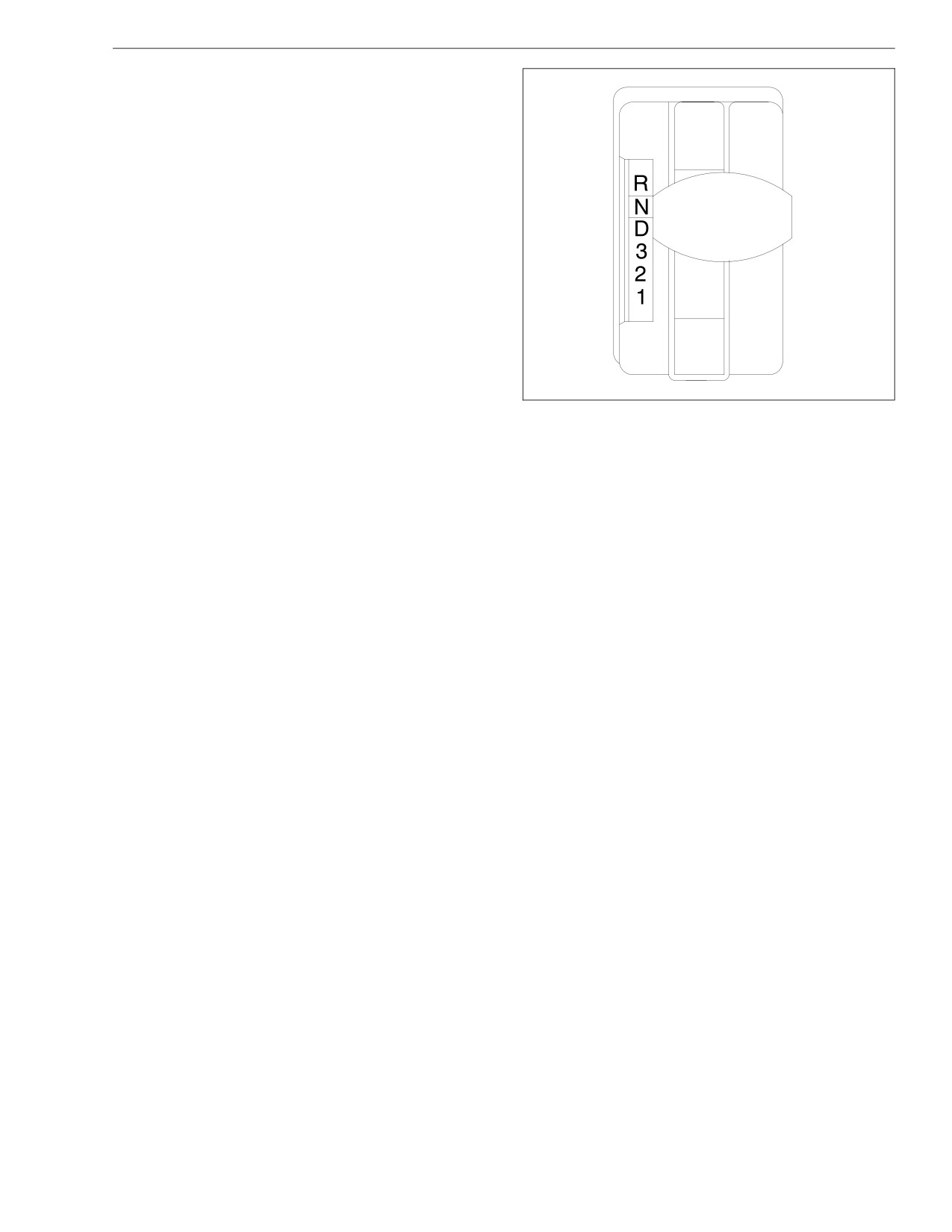
Allison automatic transmissions have six shift positions
on the selector lever. See Fig. 2.7. The selector lever is
lighted for night driving. See Chapter 5 for complete
transmission operating instructions.
NOTE: Vehicles equipped with an Arens shift-by-
wire shift control system have an electronic push-
button selector similar to that described below for
MD-series transmissions.
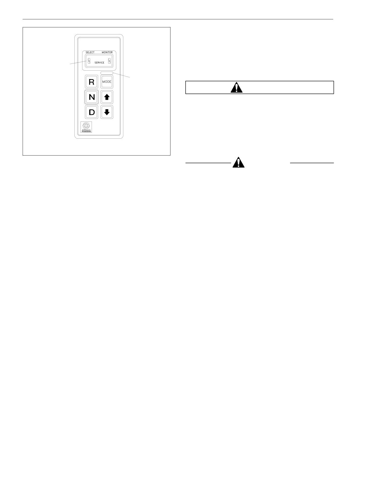
Allison automatic transmission models MD-CR and
07/09/96
f270004
MD-WR are controlled by an electronic control unit
(ECU). The ECU processes information from sensors,
Fig. 2.7, Shift Selector
pressure switches, and the shift selector to automati-
cally control the transmission according to programmed
problem with the transmission system, the lights will go
specifications. See Fig. 2.8.
out. Whenever there is a problem with the transmission
Vehicles with these transmissions have a red do-not-
system, the lights will come on and stay on as long as
shift light in the lens and bezel assembly. Also, there is
the problem exists.
a service light in the indicator panel on the shift selec-
If "service" is displayed in the indicator panel, some fea-
tor. With the ignition switch in the ON position, both
tures may not work, but the vehicle can still be driven. If
lights come on for a few seconds, then if there is no
2.6
Driver Controls and Instruments
troubleshooting procedures. See Chapter 5 for com-
plete transmission operating instructions.
Cruise Control
The cruise control allows you to automatically control
1
the speed of the vehicle. The switches that operate the
cruise control are located on the instrument panel.
2
WARNING
Do not use the cruise control system when driving
conditions do not permit maintaining a constant
speed, such as in heavy traffic or on roads that are
winding, icy, snow covered, slippery, or with a loose
driving surface. Failure to follow this precaution
could cause a collision or loss of vehicle control,
10/28/94
f600368a
possibly resulting in personal injury or property
damage.
1. Indicator Panel
2. Mode ID
Fig. 2.8, MD Shift Selector
CAUTION
the do-not-shift light illuminates while driving (accompa-
nied by eight short beeps from the shift selector), oper-
Do not shift to Neutral (N) when using the cruise
control. This will cause the engine to overspeed,
ating limits will be placed on the transmission, such as
restricting upshifts and downshifts. However, the vehicle
which can damage the engine.
can still be driven to reach service assistance. In either
Use the Cruise ON/OFF switch on the instrument panel
situation, have the problem repaired as soon as pos-
to turn the cruise control on or off. Use the
sible. See the Allison Transmission Service Manual for
SET/RESUME switch to select cruise speed or to re-
sume cruise control after slowing down. See Chapter 3.
2.7
Driver Controls and Instruments
High Idle (with cruise control option)
• The green right- and left-turn signal lights, that
flash on and off whenever the outside turn signal
Place the shift lever in Neutral (N). Press the ON/OFF
lights are flashing.
switch on the instrument panel. Accelerate to the de-
sired rpm. Press and release the SET/RESUME switch.
• The blue high-beam indicator light (located above
To disengage high idle, step on the brake pedal or
the speedometer and tachometer), that comes on
move the ON/OFF switch to the OFF position.
when the headlights are on high beam.
• The red parking brake indicator light, that comes
Tilt/Telescope Steering Column
on when the parking brake is applied and the ig-
nition switch is in the ON position. See Fig. 2.9.
(optional)
The optional tilt/telescope steering column is actuated
Standard Warning System
by a control lever on the steering column.
Standard Warning Lights
The optional tilt-only steering column is actuated by ei-
ther a control lever on the steering column or a foot-
Standard red warning lights are for alternator no-
operated control valve located to the left of the clutch or
charge, and the brake system warning. See Fig. 2.9.
brake pedal.
Whenever conditions cause the brake system warning
light to come on, a warning buzzer also alerts the
Electric Horn
driver.
On hydraulic brake systems, the warning light comes on
To sound the electric horn, push the button in the center
and the buzzer sounds when the fluid level is low, or
of the steering wheel.
whenever there is a fluid pressure problem within the
master cylinder.
Warning and Indicator Lights
The oil pressure warning light and buzzer activate
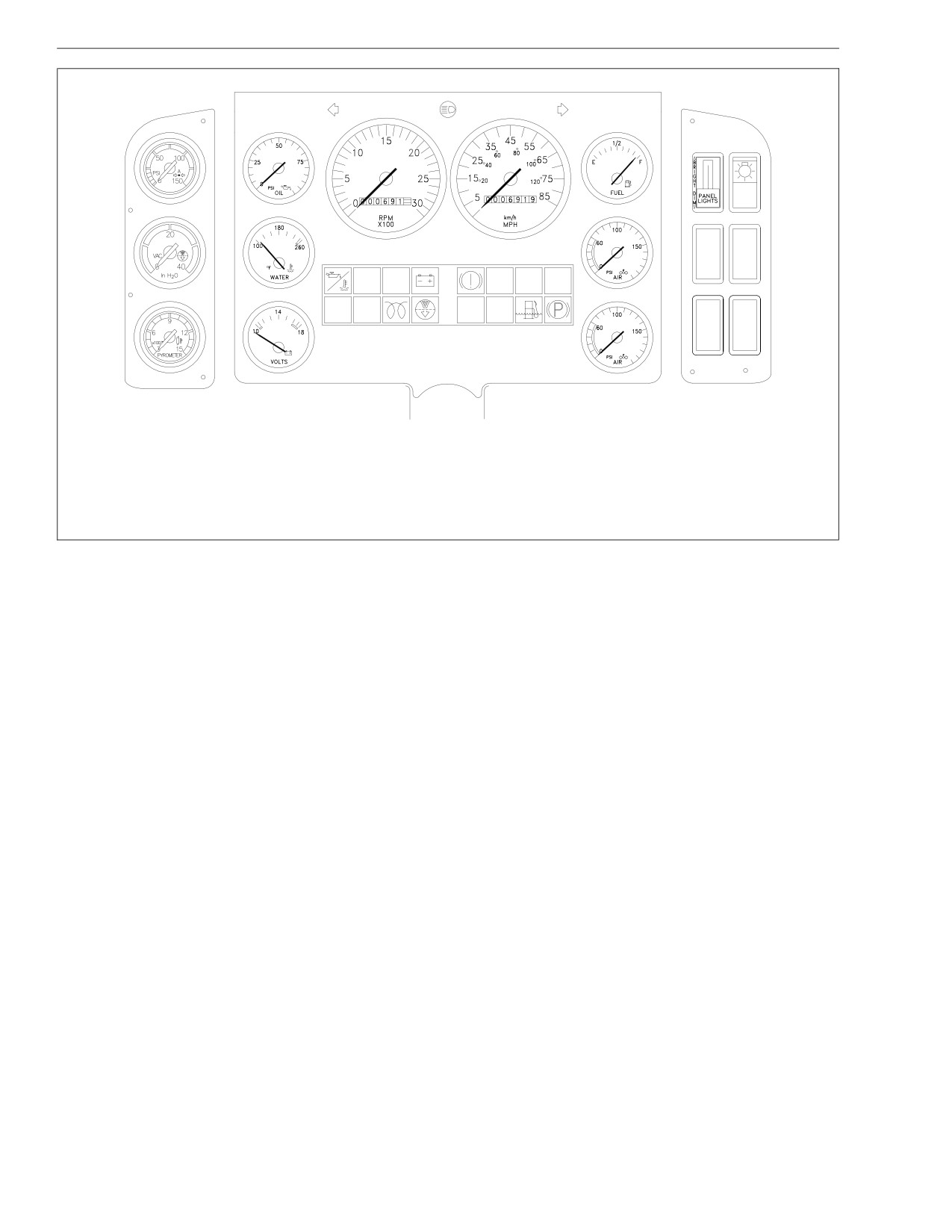
All of the standard and optional warning and indicator
whenever the oil pressure falls below the minimum oil
lights are housed in a lens and bezel assembly, located
pressure recommended by the engine manufacturer.
below the speedometer and tachometer.
See Fig. 2.9.
Standard indicator lights include:
2.8
Driver Controls and Instruments
1
2
3
4
5
LOW
ABS
OIL
ENG
ENG
DO NOT
TRANS
DOWN
CHK
SHIFT
TEMP
6
7
8
9
10
11
12
13
09/12/96
f601176
1. Low Oil Pressure/High Water
6. Stop Engine Indicator
11. High Oil Temperature Warning
Temperature Warning
7. Engine Check Indicator
(automatic transmission)
2. Low Oil Level Warning
8. Cold Start Manifold Heater
12. Water in Fuel/Water Separator
3. Alternator Warning Light
Indicator
Warning
4. Brake System Warning
9. Air Cleaner Restriction Indicator
13. Parking Brake Indicator Light
5. Antilock Braking System (ABS)
10. Do Not Shift Indicator
Warning Light
Fig. 2.9, Warning and Indicator Lights
2.9
Driver Controls and Instruments
See the engine manufacturer’s manual for minimum oil
Optional warning and indicator lights may include: air
pressure levels.
intake warmer, transmission oil temperature, air cleaner
restriction, check engine, and engine shutdown.
The water temperature warning light and buzzer acti-
vate whenever the engine coolant temperature exceeds
When the ignition switch is turned to the ON position,
a preset point determined by the engine manufacturer.
oil and brake system warnings (as equipped) activate
See Fig. 2.9.
until the engine starts and minimum pressures are ex-
ceeded. If the low oil pressure warning light or brake
See the engine manufacturer’s manual for maxi-
system warning light remains on after running the en-
mum water temperature levels.
gine for 15 seconds, shut down the engine and deter-
mine the cause of the problem. See the School Bus
Optional Warning and Indicator Lights
Chassis Workshop Manual for repair procedures.
IMPORTANT: If the warning system does not acti-
CAUTION
vate when the ignition switch is turned to the ON
position, repair the system to provide warning pro-
The vehicle may be programmed for the engine to
tection for oil pressure, coolant temperature, and
derate and eventually shut down if there is a loss of
the brake system.
oil pressure or if coolant temperature becomes too
high. This protects the engine from damage. Under
these conditions, first the check engine light will
Instruments
come on. If the driver continues to drive the vehicle,
the engine derate or shut down light will come on
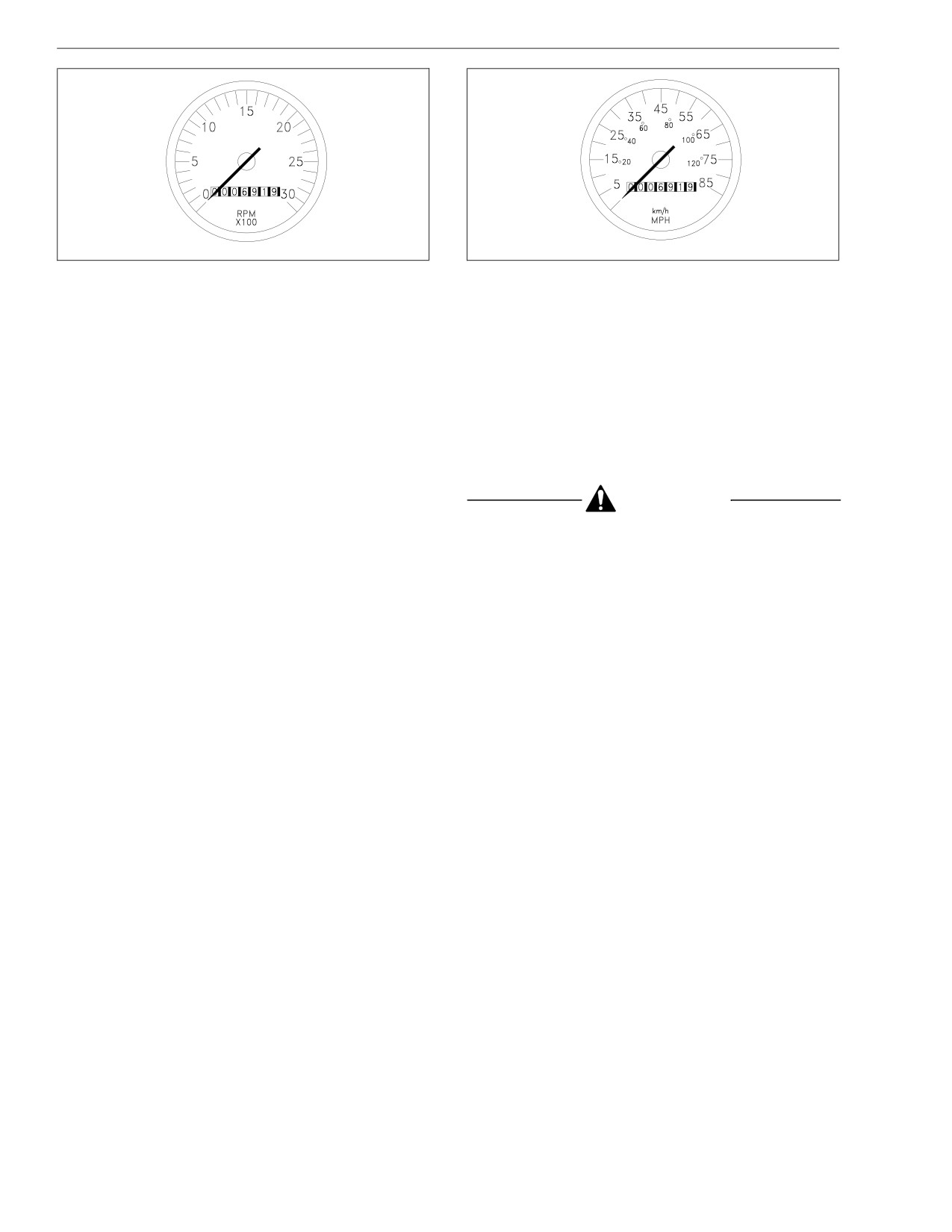
Tachometer (optional)
and the engine will start to power down or derate.
A tachometer indicates engine speed in revolutions per
Eventually the engine will shut down. Be aware that
minute (rpm), and serves as a guide for shifting the
the vehicle could derate and/or shut down if this
transmission and keeping the engine in the appropriate
option is programmed. Be prepared to park the ve-
rpm range. See Fig. 2.10. For low idle and rated rpm,
hicle in a safe location if it does derate or shut
see the engine identification plate.
down.
The tachometer may include an engine hourmeter. An
engine hourmeter records continuous operating hours of
2.10
Driver Controls and Instruments
10/28/94
f600374a
10/28/94
f600375a
Fig. 2.10, Tachometer
Fig. 2.11, Speedometer
the engine. In cases where actual mileage does not in-
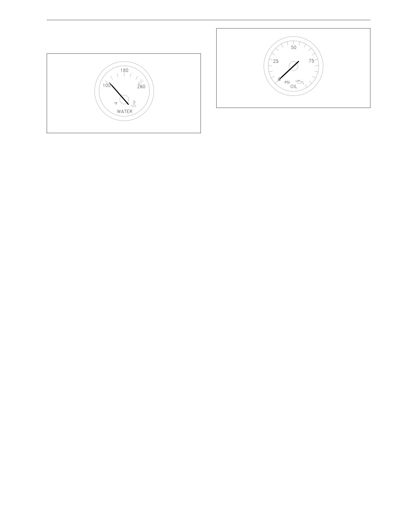
Fig. 2.12. If the temperature remains below 160°F
dicate overall usage, maintenance and lubrication inter-
(71°C) or exceeds a maximum temperature of 210°F
vals for the engine and engine-operated equipment can
(99°C), inspect the cooling system to determine the
be determined by operating hours.
cause. See the School Bus Chassis Workshop Manual
for troubleshooting and repair procedures.
Speedometer
Engine Oil Pressure Gauge
A speedometer registers vehicle speed in both miles
per hour (mph) and kilometers per hour (km/h). Stan-
See the engine manufacturer’s manual for recom-
dard speedometer gauges are equipped with an odom-
mended engine oil pressure gauge readings. See
eter that records total distance traveled in either miles
Fig. 2.13.
or kilometers. See Fig. 2.11.
CAUTION
Water Temperature Gauge
During normal engine operation, the water temperature
A sudden decrease or absence of oil pressure may
gauge should read from 175 to 203°F (79 to 95°C). See
indicate mechanical failure. Bring the vehicle to a
2.11
Driver Controls and Instruments
safe stop and investigate the cause to prevent fur-
ther damage. Do not operate the engine until the
cause has been determined and corrected.
10/28/94
f600377a
Fig. 2.13, Engine Oil Pressure Gauge
10/28/94
f600376a
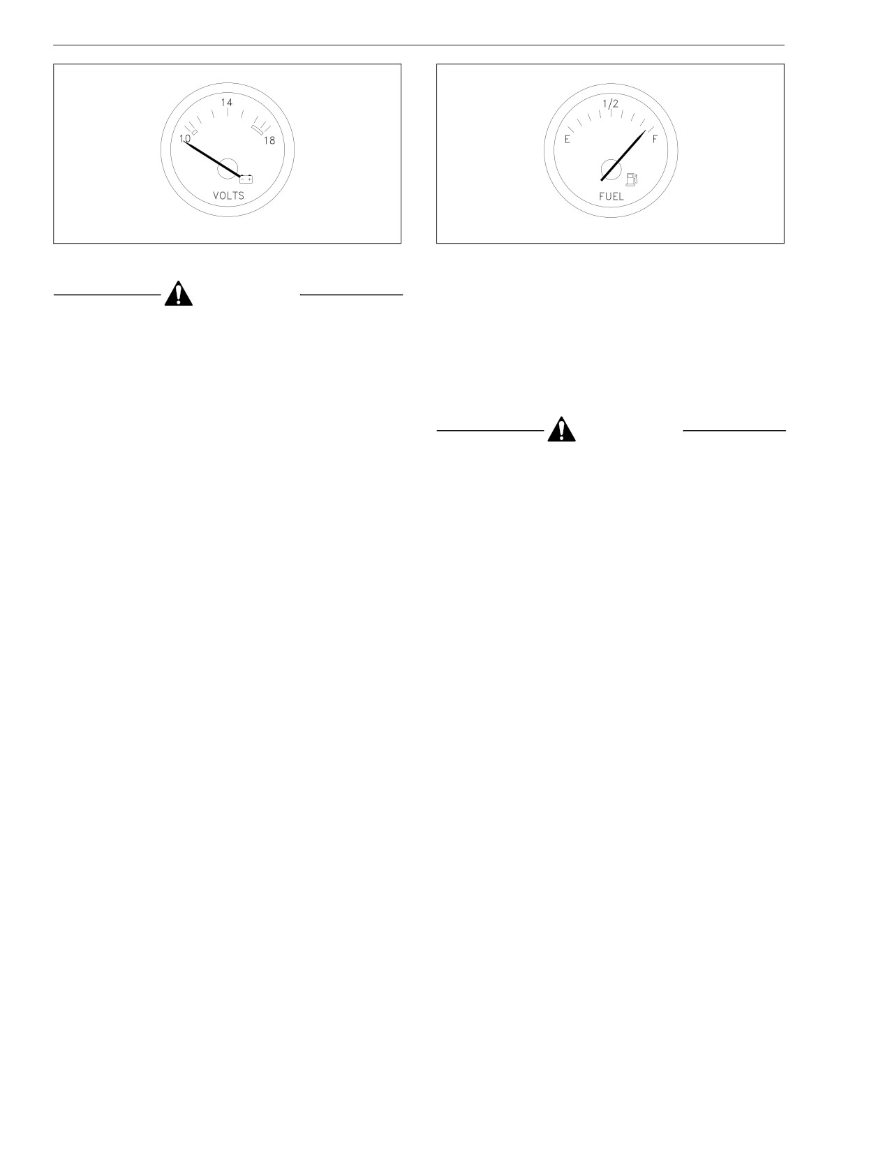
gine is stopped. A completely discharged battery will
produce only about 12.0 volts. The voltmeter will indi-
Fig. 2.12, Water Temperature Gauge
cate lower voltage as the vehicle is being started or
when electrical devices in the vehicle are being used.
Voltmeter (optional)
If the voltmeter shows an undercharged or overcharged
The voltmeter indicates the vehicle charging system
condition for an extended period, have the charging
voltage when the engine is running and the battery volt-
system and batteries checked at a repair facility.
age when the engine is stopped. See Fig. 2.14. By
NOTE: On a vehicle equipped with a battery isola-
monitoring the voltmeter, the driver can be aware of po-
tor system, the voltmeter measures the average
tential charging system problems and have them re-
voltage of all of the batteries when the engine is
paired before the batteries discharge enough to create
starting difficulties.
running. When the engine is stopped, the voltme-
ter shows only the gel cell battery voltage and
The voltmeter will normally show approximately 13.7 to
does not indicate the voltage of the engine-starting
14.1 volts when the engine is running. The voltage of a
batteries.
fully charged battery is 12.7 to 12.8 volts when the en-
2.12
Driver Controls and Instruments
10/28/94
f600378a
10/28/94
f600380a
Fig. 2.14, Voltmeter
Fig. 2.15, Fuel Gauge
Transmission Oil Temperature Gauge
CAUTION
(optional)
Gel cell batteries can be damaged if the battery
With an Allison automatic transmission, the transmission
voltage is allowed to drop below 12.0 volts or if the
oil temperature gauge reading should not exceed 300°F
charging voltage is more than 14.1 volts. Start the
(149°C) during normal operation. A warning light will
engine to recharge the gel cell before the battery
illuminate to alert the driver if normal operating tem-
becomes fully discharged. If an external charger is
peratures are exceeded.
needed, disconnect the gel cell battery and use only
an external battery charger that has been approved
for gel cell batteries.
CAUTION
Fuel Gauge
A sudden increase in transmission oil temperature
that is not caused by a load increase may indicate
The fuel gauge indicates the amount of fuel in the fuel
mechanical failure. Bring the vehicle to a safe stop,
tank(s). See Fig. 2.15.
2.13
Driver Controls and Instruments
and investigate the cause to prevent further dam-
Maximum Air Restriction in Inches of Water (inH2O)
age. Do not operate the vehicle until the cause has
At Full Load and At No-Load and
been determined and corrected.
Engine
Governed RPM Governed RPM
Caterpillar
25
(63 cm)
12
(30 cm)
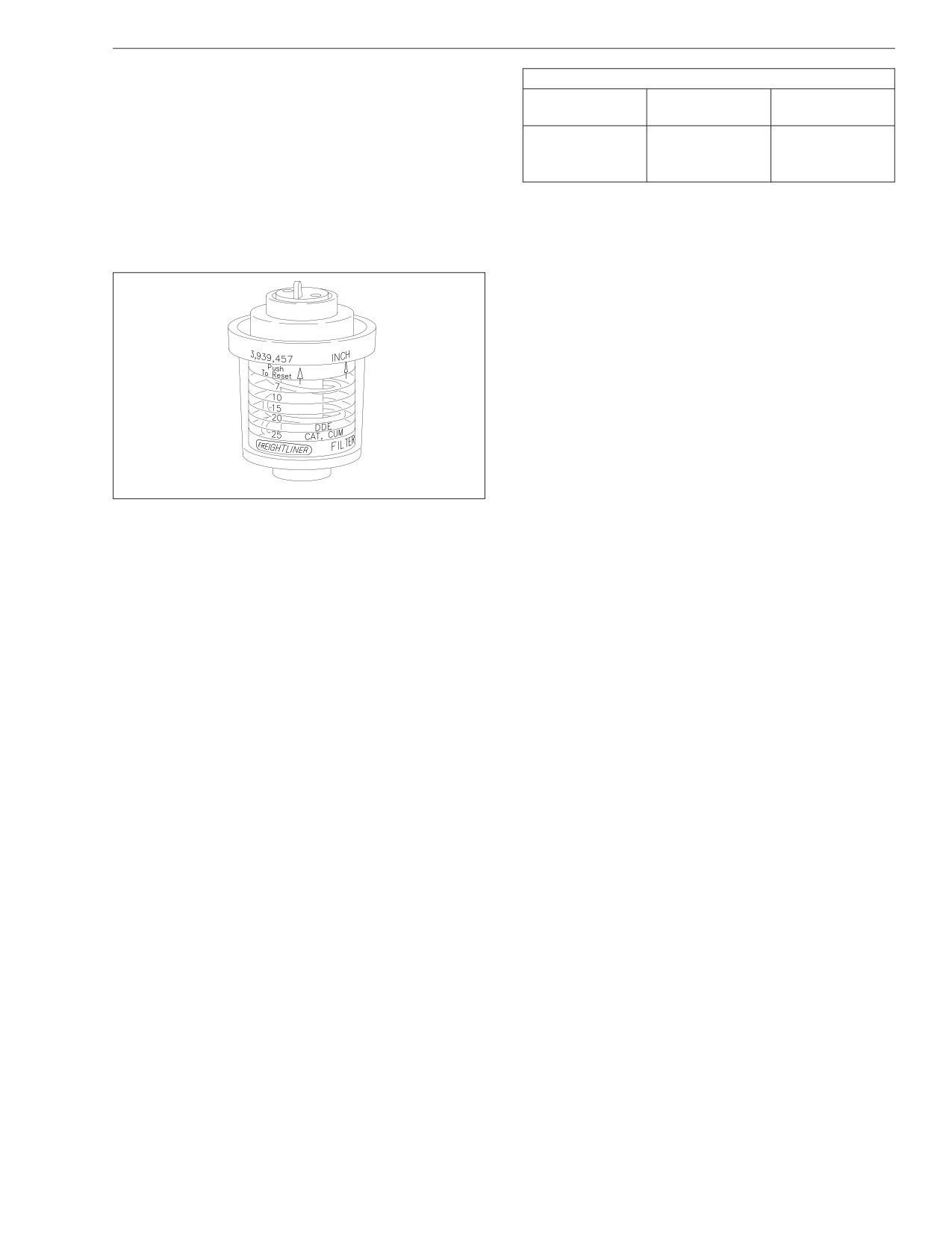
Intake-Air Restriction Indicator
Cummins
25
(63 cm)
12
(30 cm)
An intake-air restriction indicator measures the vacuum
Mercedes-Benz
25
(63 cm)
12
(30 cm)
on the engine side of the air cleaner at the air cleaner
outlet. See Fig. 2.16. If the yellow signal stays locked at
Table 2.1, Maximum Air Restriction in Inches of Water
or above the values shown in Table 2.1 after the engine
(in H2O)
is shut down, service the air cleaner. Then, press the
NOTE: Rain or snow can wet the filter and cause
yellow button to reset the indicator.
a higher than normal reading temporarily.
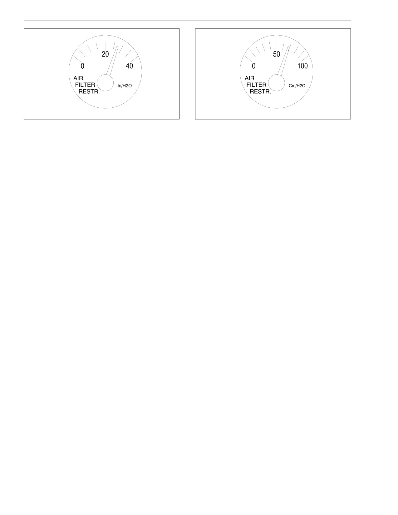
Intake-Air Restriction Gauge
The intake-air restriction gauge measures the vacuum
on the engine side of the air cleaner at the air cleaner
outlet. See Fig. 2.17 and Fig. 2.18. Vacuum is mea-
sured in inH2O (inches/centimeters of water). When the
vacuum reading in normal operation equals the appli-
cable level shown in Table 2.1, the air cleaner needs to
be serviced.
IMPORTANT: Do not rely exclusively on the accu-
racy of the air restriction gauge for filter replace-
ment. The filter must be changed at recommended
01/18/95
f600148a
intervals regardless of what the gauge reads.
Fig. 2.16, Intake-Air Restriction Indicator
NOTE: Rain or snow can wet the filter and cause
a higher than normal reading temporarily.
2.14
Driver Controls and Instruments
05/14/2001
f610552
05/14/2001
f610553
Fig. 2.17, Intake-Air Restriction Gauge (inH2O)
Fig. 2.18, Intake-Air Restriction Gauge (cm H2O)
• a set of 18 warning and indicator lights similar to
Instrumentation Control Unit,
those found on a conventional lightbar
Level III
• a 10-key keypad on the auxiliary instrument panel
The level III instrumentation control unit (ICU2M) is an
• a message display screen
advanced programmable electronic dashboard. It can
The message display screen is a 2-line by 20-character
accept information from the sensors and electronic con-
trol units installed on the vehicle and feed it to elec-
vacuum fluorescent display that provides a wide range
of information to the driver.
tronic gauges. Only air gauges operate mechanically.
Some of the information that can be provided by the
There can be up to 14 removable gauges on the driv-
message center includes:
er’s instrument panel (11 electronic, one electrome-
chanical, and two mechanical).
• odometer readings
The Driver Message Center is the heart of the level III
• outside air temperature
ICU. It has three parts:
2.15
Driver Controls and Instruments
• trip information, such as trip miles and hours, idle
The messages this system displays are:
hours, average mph, and leg miles and hours
• "Drive 60 MPH, Gain X MPG"
• fuel information, such as fuel used, miles per gal-
• "Shift to Next Gear, Gain X MPG"
lon, and fuel used idling
• "End Idling, Save X Gal/Hr"
• engine information, such as miles, hours, and
gallons of fuel used
• "Drive Steady Speed, Gain X MPG"
• diagnostic information, such as listings of active
• "Move Throttle Slower, Gain X MPG"
faults and troubleshooting information
In each example, the X value in the statement is vari-
• vehicle information, such as datalink operation
able. The system will estimate and display a numerical
and use data, dash part number, and software
savings gain in place of the X.
number
NOTE: The information provided by the FUEL effi-
Some of the advanced features supported by the level
ciency system is different than, and should not be
III ICU are: Fuel Use Efficiency Level (FUEL) system
confused with, the information available by press-
display, target miles per gallon (MPG), and brightness
ing the FUEL key on the 10-key keypad. The key-
control.
pad and its direct access keys are described in
more detail later in this chapter.
Fuel Use Efficiency Level (FUEL)
If so equipped, the FUEL system continuously monitors
Target MPG
fuel usage efficiency and instantly transmits action mes-
The target MPG feature allows quick and easy checking
sages through the Driver Message Center to help the
of fuel economy through the "MPG Graph/Target MP-
driver get better mileage. The system may suggest a
G..Odometer" screen. See Fig. 2.19.
different speed, gear, or throttle position, and will calcu-
late and transmit estimated fuel savings based on the
NOTE: Use the LEFT ARROW key to lower the
suggested action. It also calculates and displays a bar
target MPG, and the RIGHT ARROW key to raise
graph that shows a fuel efficiency score as a percent-
it. For more information on how to set target MPG,
age of optimum efficiency.
2.16
Driver Controls and Instruments
Brightness Control
The panel light dimmer switch normally controls the
−
0%II
+
brightness of all panel and gauge lights, including the
level III ICU message display screen. With the parking
12.3MPG
9012.0MI R
brake set, the ICU keypad can control the brightness of
the message display screen independently of the other
10/31/2000
f601412b
lights. If the panel lights are set to maximum brightness,
the message display screen cannot be brightened any
Fig. 2.19, MPG Graph/Target MPG.Odometer Screen
further.
adjust screen display brightness, change lan-
NOTE: Use the LEFT ARROW key to dim the
guages or switch between US and metric units of
message display screen, and the RIGHT ARROW
measure, see "Setup Information" later in this
key to brighten it. For more information on how to
chapter.
set the brightness of the message display screen,
The "Target MPG" area is on the second line of the dis-
see "Setup Information" later in this chapter.
play, to the left of the odometer. It shows the actual tar-
When the parking brake is released, the arrow keys no
get miles per gallon (MPG).
longer work to change the brightness of the message
Example: A reading of "12.3 MPG" indicates that the
display screen, but the settings stay in effect unless the
target MPG is 12.3 miles per gallon.
headlights are turned on. With the headlights on, the
message display screen dims slightly to adjust to night-
The "MPG Graph" on the first line of the display gives
time conditions.
the same information in dynamic form. The "0%" mark
in the center of the line gives the target MPG. Bars
Warning and Indicator Lights
showing to the right of the display indicate that short
term fuel economy is above the target; bars showing to
There can be up to 18 warning and indicator lights in-
the left of the display indicate that short term fuel
stalled in the level III ICU. See Fig. 2.20.
economy is below the target.
2.17

Driver Controls and Instruments
• The green right- and left-turn signal lights flash
•
The blue high-beam indicator light comes on
on and off whenever the outside turn signal lights
when the headlights are on high beam.
are flashing.
•
The yellow "Check Engine" (CHK ENG) light
comes on to indicate an engine condition such as
1
2
3
6
7
8
9
low coolant level, high coolant temperature, or
low oil pressure. It also comes on when a fault is
detected or recorded.
FASTEN SEATBELTS
10
•
The red "Engine Protection" (ENG PROT) light
0000432 MILES
comes on to warn that the protection system
11
available on the engine has been activated.
•
Installed on Cummins engines only, the red "Stop
4
5
5
12
Engine" (STOP ENG) light comes on to warn that
08/28/2002
f600996d
the engine is not functioning normally. Pull the
vehicle over to the side of the road and shut
Typical installation shown. Location and function of
down the engine immediately.
optional lights may vary.
1. Left-Turn Indicator
•
The red low air pressure (LOW AIR) warning light
2. Engine Protection Warning Lamp Indicator
and buzzer come on whenever air pressure in the
3. Check Engine Indicator
primary or secondary air reservoir falls below 64
4. Stop Engine Warning
to 76 psi (440 to 525 kPa).
5. Optional Indicator
6. Message Display Screen
•
Depending on options installed, other warning
7. High-Beam Indicator
and indicator lights can be installed in the spaces
8. Low Air Warning
marked "OPT." Available optional indicator lights
9. Right-Turn Indicator
include: air bag warning, alternator no charge
10. Air Bag Warning (optional)
warning, automatic transmission overheat warn-
11. ABS Warning
ing, trailer ABS warning, ECAS (electronic sus-
12. Wheel Spin Indicator
pension) transfer indicator, and ECAS failure
warning.
Fig. 2.20, Driver Message Center, Level III ICU
2.18
Driver Controls and Instruments
NOTE: The functions of the ABS warning light are
• Set the brightness of the message display screen
explained under "Meritor WABCO Antilock Braking
independently of the panel dimmer switch. Use
the LEFT ARROW key to dim the display and the
System (ABS)" in Chapter 7.
RIGHT ARROW key to brighten it.
Keypad
• Record significant data using the EVENT key
(optional—if a data logging unit is installed).
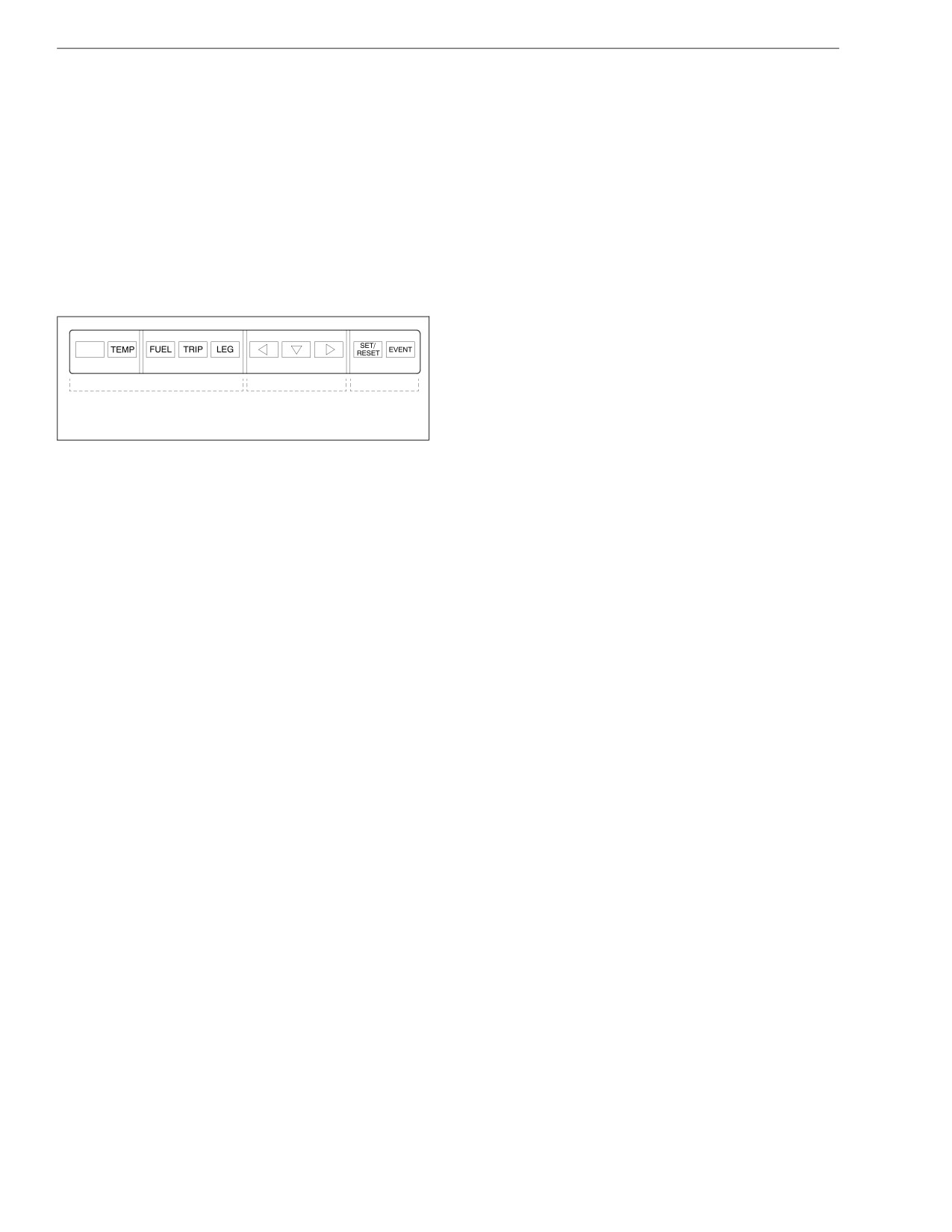
The level III ICU is controlled by a keypad located on
the auxiliary dash panel. See Fig. 2.21. This keypad,
NOTE: One key is blank and is not usable at this
which has 10 keys, can be used to:
time.
• Call up information onto direct access screens.
Level III ICU Ignition Sequence
• Move about from screen to screen while the ve-
hicle is stationary.
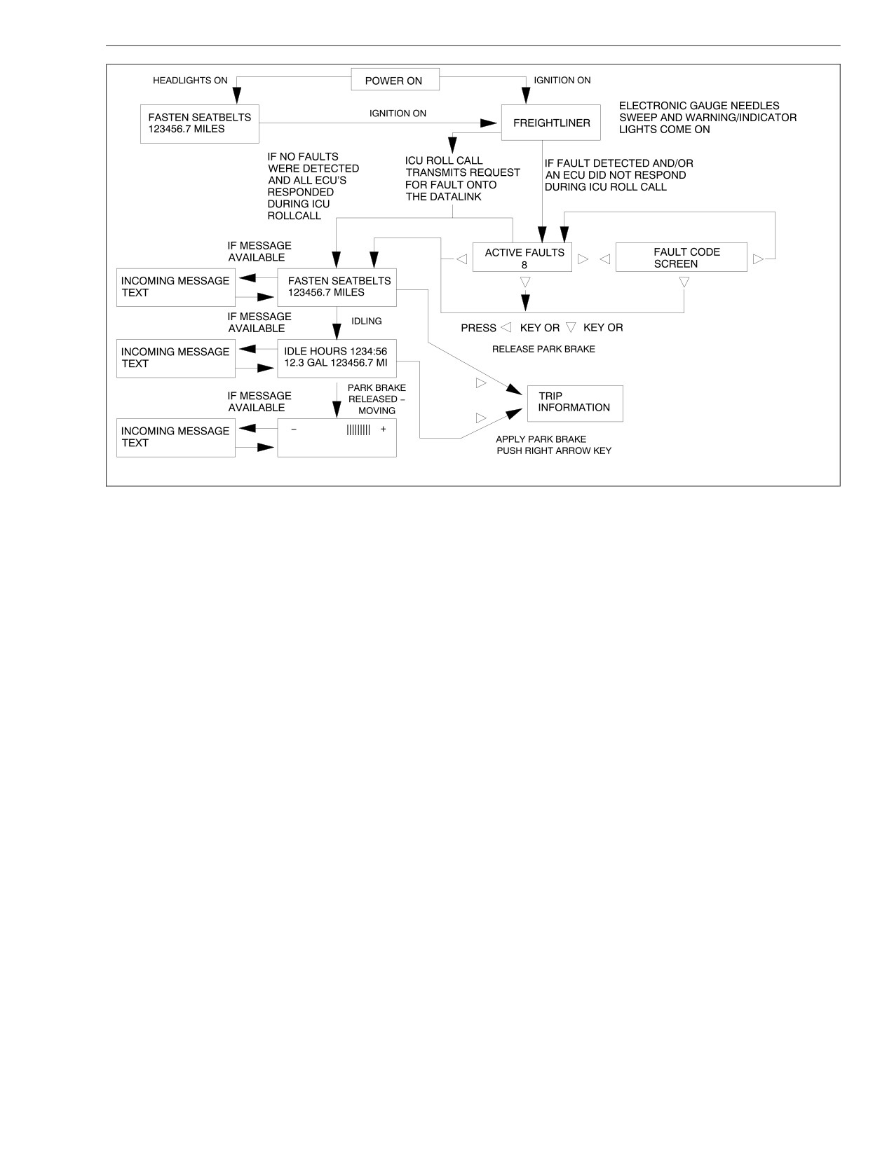
If the headlights are turned on, the screen displays the
odometer and waits for the ignition switch to be turned
• Set up the display.
to the ON position.
When the ignition switch is first turned to the ON posi-
tion, all of the electronic gauges complete a full sweep
of their dials, the warning and indicator lights light up for
five seconds, and the buzzer sounds for two seconds.
See Fig. 2.22.
Dedicated Keys
General Keys Control Keys
NOTE: The air gauges and voltmeter do not
08/08/96
f601009
sweep.
Fig. 2.21, 10-Key Keypad
Once the ignition switch has been turned to the ON po-
sition, the screen displays the "Freightliner" message. At
• Set a target MPG to monitor fuel economy while
the same time, the level III ICU conducts a roll call of all
driving. Press the LEFT ARROW key to lower the
of the electronic control units (ECUs) installed on the
target MPG and the RIGHT ARROW key to raise
vehicle, looking for active faults.
it.
2.19
Driver Controls and Instruments
0%
12.3 TMPG 123456.7 MI
03/18/98
f040415
Fig. 2.22, Ignition Sequence, Level III ICU
2.20
Driver Controls and Instruments
If there are no active faults, the screen displays the
"Fasten Seat Belts/Odometer" screen.
If, however, the level III ICU has received active fault
codes or an electronic control unit (ECU) fails to re-
spond to the roll call, it shows the "Active Faults" screen
and displays the number of active faults up to a total of
eight. If desired, press RIGHT ARROW to see the ac-
tive fault codes. See Fig. 2.19. Continuing to press the
right arrow key will display all additional fault codes (if
any).
To go on, press LEFT ARROW, or if the engine is run-
ning, release the parking brake to go on to the "Fasten
Seat Belts/Odometer" screen.
Unless the engine is running, the ignition sequence
07/29/97
f601415
ends with the "Fasten Seat Belts/Odometer" screen.
Fig. 2.23, Level III ICU at the End of the Ignition
IMPORTANT: At this point, if the vehicle has a
Sequence
communications system and an incoming mes-
sage is available, it will be displayed. To dismiss
The Message Display Screen
the incoming message, press any key on the key-
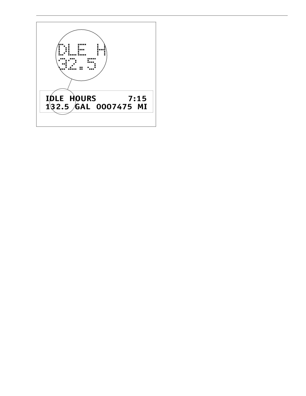
To understand the information displayed on the mes-
pad.
sage display screen, here is an example of screen lay-
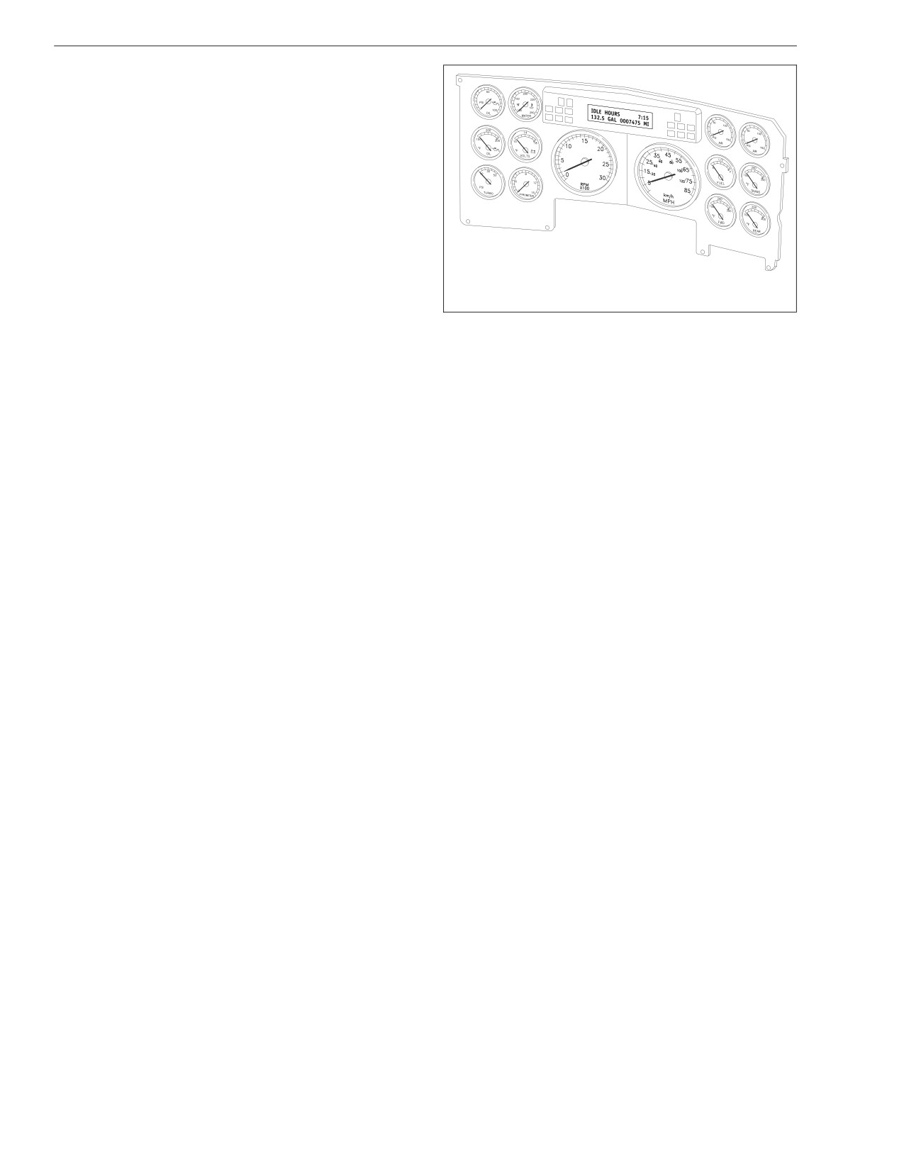
With the engine idling (the vehicle not moving), the igni-
out. On the "Idle Hours/Idle Gallons..Odometer" screen,
tion sequence cycles on, and displays the "Idle Hours/
idle hours are displayed on the top line with the words
Idle Gallons..Odometer" screen. See Fig. 2.23.
"Idle Hours" on the left side of the screen and the num-
ber of hours on the right. On the bottom line, the num-
ber of idle gallons is on the left and the odometer miles
are on the right, with a space in between. See
Fig. 2.24.
2.21
Driver Controls and Instruments
NOTE: Press the LEFT ARROW key to lower the
target MPG and the RIGHT ARROW key to raise
it. For more information on how to set the target
MPG, see "Setup Information" later in this chapter.
Level III ICU Roll Call
Each time that the ignition switch is turned to the ON
position, the level III ICU roll call function requests data
from each ECU on the databus. If the ECU does re-
spond to this request, the databus is communicating
with that ECU and no fault code is displayed.
NOTE: Each ICU is configured to receive re-
sponses from a list of selected ECUs as installed
on that particular vehicle.
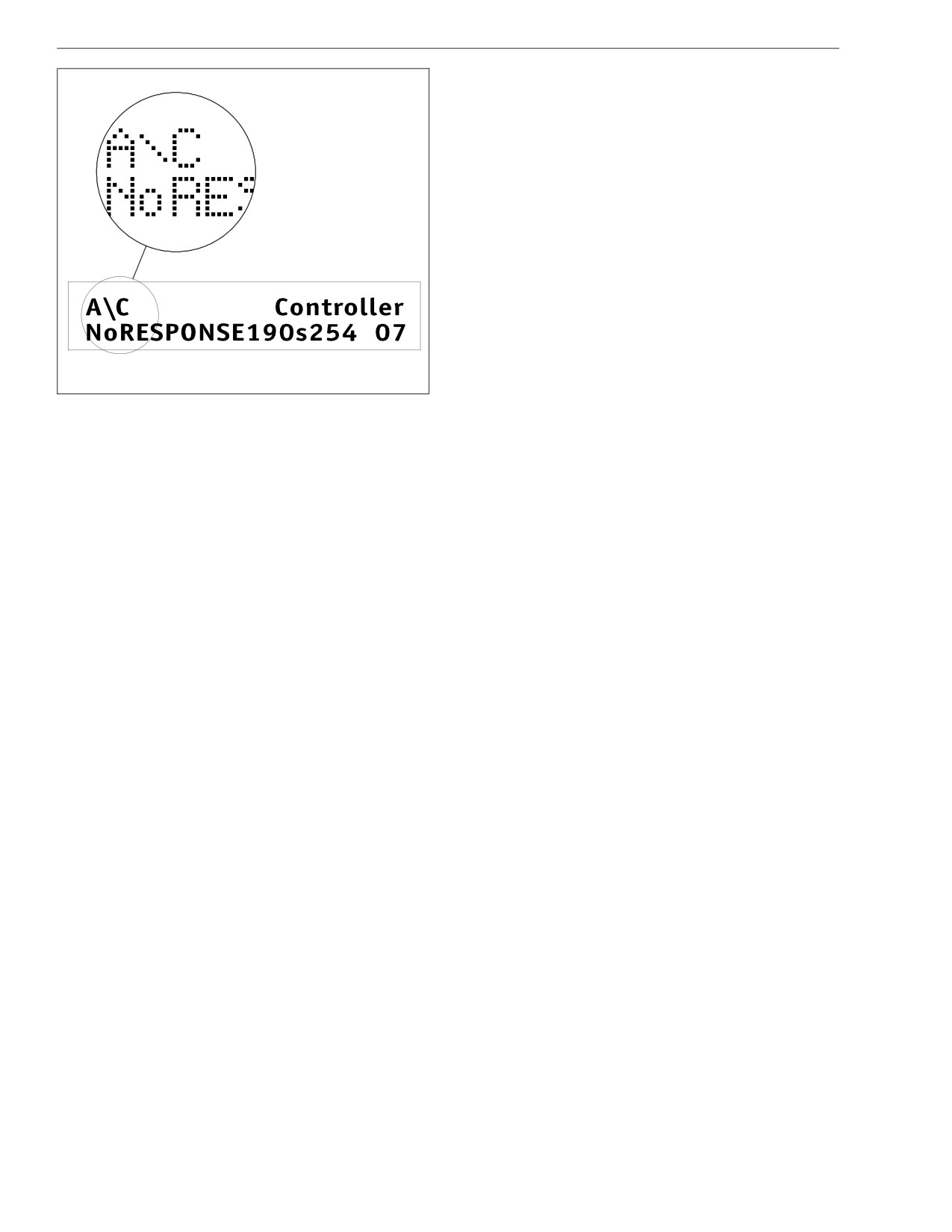
If the ECU does not respond to this request, the level III
ICU displays an active fault code that indicates that the
07/29/97
f601411
databus is not communicating with that ECU. For a
sample fault code and message of this type, see
Fig. 2.24, Idle Hours/Idle Gallons..Odometer Screen
Fig. 2.25.
Once the parking brake is released (whether the vehicle
Level III ICU Odometer
is moving or not), the regular message screen display is
the "MPG Graph/Target MPG..Odometer" screen. The
The level III ICU odometer is a seven-digit display with
MPG graph is a dynamic display graph demonstrating
one decimal point after the sixth digit allowing it to dis-
how the actions of the driver affect fuel economy. The
play tenths of miles (or kilometers).
graph moves to the right as fuel economy improves.
When first installed, the odometer starts at 0.0 miles (or
See Fig. 2.19.
kilometers). When replaced, the odometer does not
2.22
Driver Controls and Instruments
Alert Screens
Alert screens appear whenever a condition requiring an
alert occurs. They appear when the vehicle is moving;
they override the regular screen display. They are warn-
ings, cautions, or other messages that require the driv-
er’s attention, but not all of them are critical to the op-
eration of the vehicle. Warning messages always
display at full brightness.
More important messages take priority over less impor-
tant messages. The order of importance, or priority, is:
1. Eaton VORAD Warnings (if so equipped)
2. Parking Brake On (with the vehicle moving)
3. Low Oil Pressure, High Coolant Temperature, Low
Coolant Level, and Low Voltage
4. Alternate Speedometer
07/29/97
f601413
5. Recirc Mode Engaged, and Provide Fresh Air
6. Low Fuel Level
Fig. 2.25, Level III ICU Roll Call Fault Code and
Message
7. Turn Signal On
start with the engine miles but starts again from 0.0 and
8. Service Warnings
cannot be changed up or down.
9. No Datalink Activity
IMPORTANT: Although the odometer uses data
"Parking Brake On" Screen
supplied by the engine ECM to update its count, it
keeps its own mileage starting from the zero point,
This warning message and alarm tone come on when-
which marks where it was first installed.
ever the parking brake is applied and the vehicle is
2.23
Driver Controls and Instruments
moving faster than 2.5 miles per hour or the clutch has
NOTE: If there is more than one alert message to
been depressed. The word "Warning" flashes on the
display, pressing any key takes you to the next
message display screen above the message "Parking
message, and so on until all of the messages
Brake On." The screen and alarm tone go away only
have been received.
when the parking brake is released. See Fig. 2.26.
If low oil pressure is detected during the ignition se-
quence, it displays as an active fault and the alert
screen does not appear.
After 30 seconds, this message displays again and can
be dismissed as before by pressing any key.
"Low Coolant Level" Screen
07/29/97
f601414
This warning message and alarm tone activate when-
ever the coolant level falls below a preset point. The
Fig. 2.26, Parking Brake On Screen
word "Warning" flashes on the message display screen
above the message "Low Coolant Level."
The "Parking Brake On" screen overrides any other
screen message.
This message follows the same rules of dismissal and
display as "Low Oil Pressure."
"Low Oil Pressure" Screen
"High Coolant Temp" Screen
This warning message and alarm tone come on when-
ever the oil pressure falls below the minimum oil pres-
This message and alarm tone come on whenever the
sure specified by the engine manufacturer, whether the
engine coolant temperature exceeds a preset point
vehicle is idling or in motion. The word "Warning"
specified by the engine manufacturer (see the engine
flashes on the message display screen above the mes-
manual for this temperature). The word "Warning"
sage "Low Oil Pressure." To dismiss the message,
flashes on the message display screen above the mes-
press any key on the keypad.
sage "High Coolant Temp."
This message follows the same rules of dismissal and
display as "Low Oil Pressure."
2.24
Driver Controls and Instruments
"Low Voltage" Screen
seconds every 254 seconds (about every four minutes)
until the driver switches to fresh air, either by selecting
On some vehicles, this message and alarm tone come
fresh air on the fresh/air recirculation switch or by rotat-
on whenever a low voltage condition is detected by the
ing the air circulation switch away from maximum air
instrumentation control unit. The word "Warning" flashes
conditioning and to one of the other positions.
on the message display screen above the message
"Low Voltage."
"Low Fuel Level" Screen
This message follows the same rules of dismissal and
Fuel level is continuously monitored by the ICU. When
display as "Low Oil Pressure."
the fuel level drops to 1/8th full the word "Warning"
flashes on the message display screen above the mes-
"Faulty Speedo Gauge" Screen
sage "Low Fuel Level."
This message is displayed when the system detects a
faulty speedometer. This becomes the default screen,
"Turn Signal On" Screen
and vehicle speed is displayed as a digital readout at
This warning message (the alarm tone is optional)
the bottom left of the screen. All other screens and
comes on whenever the turn signal remains on beyond
functions operate normally.
a preset time or distance traveled. The word "Warning"
flashes on the display screen above the message "Turn
"Recirc Mode Engaged" and "Provide Fresh
Signal On."
Air" Screens
To dismiss this message, either turn off the turn signal
The "Recirc Mode Engaged" screen comes on when-
or press any key on the keypad.
ever recirculated air is selected on the fresh/air recircu-
lation switch or the air circulation switch is rotated to the
Service Warnings
maximum air conditioning position. It displays one time
Service warning screens display during the ignition se-
only for seven seconds. It notifies the driver that recir-
quence and indicate that a service interval has been
culated air is being used and that fresh air needs to be
reached or exceeded, and that maintenance is required.
provided after 20 minutes.
The messages may indicate the number of miles or
If fresh air is not provided after 20 minutes, the "Provide
hours until the next service, or, once passed, the num-
Fresh Air" message is displayed. It displays for seven
ber of miles or hours ago that maintenance should have
2.25
Driver Controls and Instruments
been performed. The messages read "X Miles To Next
Data for each of the above screens can be reset
Service," "X Hours To Next Service," "Service Was Due
(cleared). To reset, display the screen and push the Set/
X Mi Ago," and "Service Was Due X Hr Ago." The letter
Reset key twice within six seconds (a confirmation
X represents the number of miles or hours pro-
screen will display after you press the key once).
grammed. The ICU2M can be programmed using Ser-
NOTE: Resetting "Trip Miles and Hours" also re-
viceLink to generate service warnings in either miles or
hours, but not both.
sets "Leg Miles and Hours."
Press the TEMP key to display the outside air tempera-
"No Datalink Activity" Screen
ture.
The "No Datalink Activity" screen comes on whenever
If the vehicle has a data logging unit, press the EVENT
the datalink is not receiving data.
key to record data about a significant driving event (en-
gine problem, driving problem, unusual vehicle opera-
If the condition persists, take the vehicle in for service
as soon as possible to discover the cause of the prob-
tion, etc.). Normally, the screen displays "Data Being
Recorded."
lem.
NOTE: If the memory in the data logger is full, the
Direct Access Screens
screen instead displays "Memory Full/Data Not
The driver can also override the regular screen display
Recorded." If the data logger is not connected or
at any time by pressing the keypad to display one of
not responding, the screen displays "Data
the direct access screens.
Recorder/Not Responding." If the EVENT key was
pressed recently (within the last two minutes), the
• Press the TRIP key for the "Trip Miles and Trip
screen displays "Still Recording/Last Event."
Hours" screen.
• Press the FUEL key for the "Fuel Used and Aver-
Stationary Access Screens—Used
age MPG" screen.
With Parking Brake Applied
• Press the LEG key for the "Leg Miles and Leg
Hours" screen.
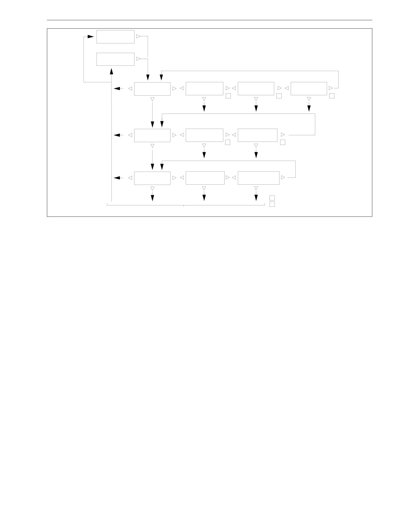
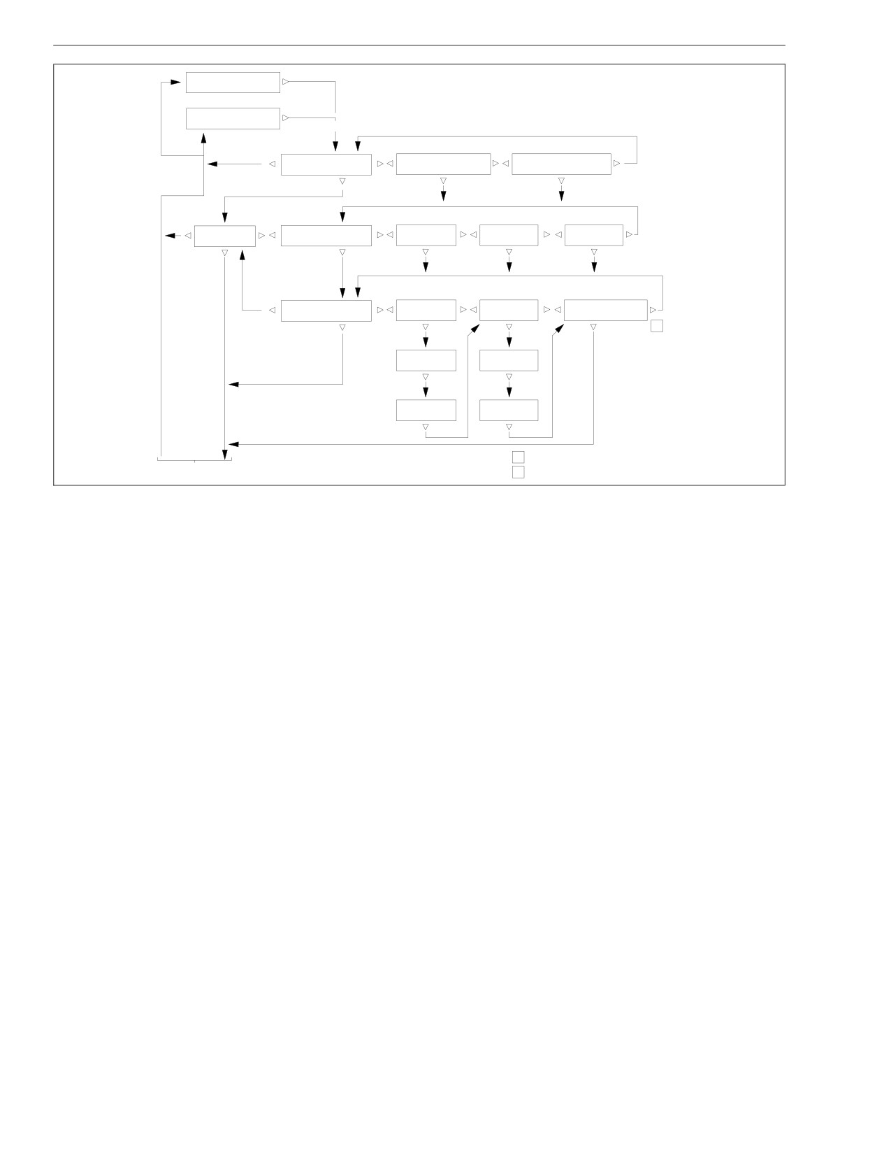
The stationary access screens are a series of informa-
tional displays that give trip, fuel, engine, diagnostic,
setup, and vehicle information.
2.26
Driver Controls and Instruments
For reasons of safety, stationary access screens can be
NOTE: Resetting "Trip Miles and Hours" also re-
seen only when the vehicle is not moving and the park-
sets "Leg Miles and Hours."
ing brake is applied.
Fuel Information
Each set of stationary access screens has a title screen
followed by one or more data screens. To move forward
Fuel information provides two data screens: "Fuel Used
and backward through these screens, use the three ar-
and Average MPG" and "Idle Gallons and PTO Gal-
row keys as shown in Fig. 2.27, Fig. 2.28, and
lons." See Fig. 2.27.
Fig. 2.29.
"Fuel Used and Average MPG" displays the gallons of
fuel used since the last reset. At the start of a trip, after
Trip Information
refueling, or whenever desired, press RESET (SET/
Trip information provides three data screens: "Trip Miles
RESET twice) to set fuel used and average miles per
and Hours," "Idle Hours and Average MPH," and "Leg
gallon back to zero.
Miles and Hours." See Fig. 2.27.
NOTE: Resetting "Trip Miles and Hours" does not
"Trip Miles and Hours" displays the number of miles
also reset "Fuel Used and Average MPG" or "Idle
and hours driven since the start of the trip. At the start
Gallons and PTO Gallons." Fuel Information must
of a trip, press RESET (SET/RESET twice) to set trip
be reset separately.
miles and hours back to zero.
"Idle Gallons and PTO Gallons" displays the gallons of
NOTE: Resetting "Trip Miles and Hours" also re-
fuel used idling and to operate the Power Take Off unit
sets "Idle Hours and Average MPH."
(if installed). At the start of a trip or whenever desired,
"Idle Hours and Average MPH" displays the hours spent
press RESET to set idle gallons and PTO gallons back
idling and the average miles per hour.
to zero.
"Leg Miles and Hours" records the number of miles and
Engine Information
hours driven since the start of the leg. At the start of a
new leg, press RESET to set leg miles and hours back
Engine information provides two data screens: "Engine
to zero.
Miles and Hours," and "Engine Gallons and PTO Gal-
lons." See Fig. 2.27 or Fig. 2.28.
2.27
Driver Controls and Instruments
IDLE HOURS 1234:56
12.3 GAL 1234567 MI
FASTEN SEATBELTS
1234567 MILES
IGNITION
ON ONLY
IDLING
TRIP
TRIP MILES 123456.7
IDLE HOURS 1234:56
LEG MILES 123456.7
INFORMATION
TRIP HOURS 1234:56
AVERAGE MPH 12.3
LEG HOURS 1234:56
R
R
R
FUEL
FUEL USED 12345.6
IDLE GALLONS 12345.6
INFORMATION
AVERAGE MPG 12.34
PTO GALLONS 12345.6
R
R
ENGINE
ENG MILES 1234567.8
ENG GALLONS 123456.7
INFORMATION
ENG HOURS 123456:78
PTO GALLONS 123456.7
R
=RESET (PUSH RESET/SET KEY TWICE)
S
=SET (PUSH RESET/SET KEY ONCE)
01/28/98
See applicable figure
f040324a
Fig. 2.27, Trip Information, Fuel Information, and Engine Information
2.28
Driver Controls and Instruments
IDLE HOURS 1234.56
12.3 GAL 1234567 MI
FASTEN SEATBELTS
1234567 MILES
See applicable Figure for trip and fuel information.
IGNITION
ON ONLY
ENGINE
ENG MILES 1234567.8
ENG GALLONS 123456.7
IDLING
INFORMATION
ENG HOURS 123456:78
PTO GALLONS 123456.7
For each fault, display fault codes and description.
DIAGNOSTIC
ACTIVE FAULTS
FIRST
SECOND
LAST
INFORMATION
1234 or NONE
For each fault, display fault codes and description.
123 HIST DASH FAULTS
PUSH RESET TO
FIRST
LAST
LAST CLEAR 1234567
CLEAR DASH FAULTS
R
LAST OCCR
LAST OCCR
FIRST OCCR
FIRST OCCR
R
=RESET (PUSH RESET/SET KEY TWICE)
02/13/96
See applicable Figure.
S
=SET (PUSH RESET/SET KEY ONCE)
f040325
Fig. 2.28, Engine Information and Diagnostic Information
2.29
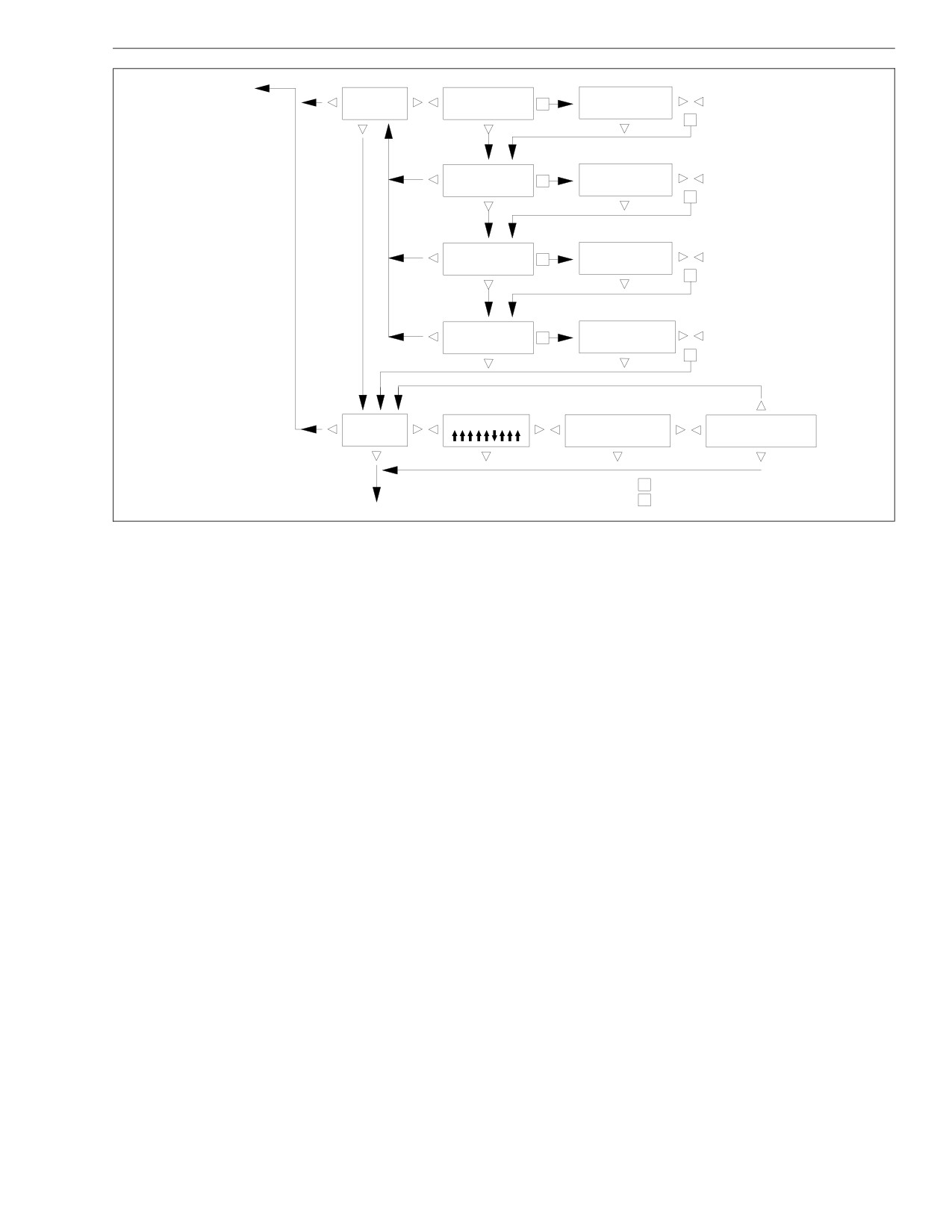
Driver Controls and Instruments
See
applicable
SETUP
PUSH SET KEY TO
TARGET MPG 7.0
S
INFORMATION
CHANGE TARGET MPG
<−−LESS MORE−−>
Figure.
S
PUSH SET KEY TO
DISPLAY BRIGHTNESS
S
CHANGE BRIGHTNESS
<−−LIGHT DARK−−>
S
CURRENT LANGUAGE
IS FLASHING
PUSH SET KEY TO
LANGUAGE ENGLISH
CHANGE LANGUAGE
S
FRENCH SPANISH
S
CURRENT UNITS
IS FLASHING
PUSH SET KEY TO
UNITS
S
ENGLISH METRIC
CHANGE UNITS
S
VEHICLE
DATA LINK ACTIVE
DATA LINK STATUS
DASH # A06−XXXXX−XXX
INFORMATION
USAGE 40% ERROR 6%
SW#
7.3.9
R
=RESET (PUSH RESET/SET KEY TWICE)
To trip information
S
=SET (PUSH RESET/SET KEY ONCE)
01/29/98
See applicable Figure.
f040326a
Fig. 2.29, Setup Information and Vehicle Information
2.30
Driver Controls and Instruments
"Engine Miles and Hours" displays the total miles and
When prompted by the screen, press SET (push the
hours logged by the engine since installation.
SET/RESET key once). The units that are setable will
be blinking. Use the arrow keys (LEFT, RIGHT, and
NOTE: Engine information is supplied by the en-
DOWN) until the display shows the desired setup.
gine Electronic Control Module (ECM). It can be
Press SET again when finished to save the new set-
reset using engine diagnostic tools. For more in-
tings. See Fig. 2.29.
formation, see the engine manufacturer’s manuals.
Vehicle Information
"Engine Gallons and PTO Gallons" displays the gallons
of fuel used by the engine and PTO since installation.
Vehicle information displays important information, in-
cluding datalink activity and status, ICU part number,
Diagnostic Information
and software identification number.
Diagnostic information provides two sets of data
The "Datalink Active" screen is a dynamic display that
screens: "Active Faults," followed by a separate screen
shows if the datalink unit is active at the given time. If
for each fault until all have been shown, and "Historical
all of the arrows are pointing down, the level III ICU has
Dash Faults," also followed by a separate screen for
not received any information on the datalink since the
each fault until all have been shown. See Fig. 2.28.
last time that the ignition switch was turned to the ON
position.
"Active Faults" cannot be reset. Active faults can be
cleared only by correcting the fault.
The "Datalink Status" screen is also dynamic, showing
current datalink use and error rate. The other screen,
"Historical Dash Faults" displays all dash faults since
which shows the ICU part number and the software
the last reset. The second line of the display shows the
identification number, is informational only. See
mileage the last time faults were cleared.
Fig. 2.29.
Setup Information
After vehicle information, pressing the DOWN ARROW
takes you back to trip information and so on.
Setup information allows the user to change the target
MPG, the brightness of the screen display, the language
of the display (English, French, or Spanish), and the
units of measurement (English/US conventional or met-
ric).
2.31
Driver Controls and Instruments
Hood Tilting
A grab handle at the front of the hood provides a hand-
hold for hood tilting. Stop cables prevent the hood from
overtravel. In the operating position, the hood is se-
cured to the lower cab half-fenders by a hold-down
latch on each side of the hood.
To Tilt the Hood:
1. Apply the parking brake.
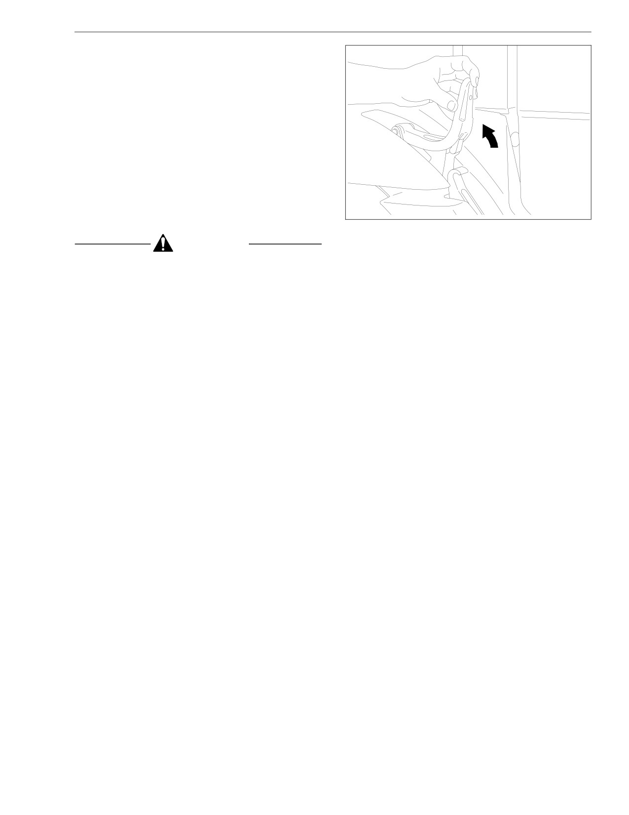
2. Release both hood hold-down latches by pulling the
ends up. See Fig. 2.30.
3. Using the bumper step and grab handle, slowly tilt
the hood until the stop cables support it. See
10/01/93
f720073
Fig. 2.31.
Fig. 2.30, Unlatch the Hood
CAUTION
2. As the hood goes over center, use the bumper step
and grab handle to control the rate of descent to
Do not let the hood free fall to the full-open posi-
the operating position.
tion. To do so could cause damage to the hood or
3. Make sure that the hood is flush with the cowl, then
hood straps.
secure the hood by engaging both hood hold-down
latches.
To Return the Hood to the Operating
IMPORTANT: Make sure that both hold-down
Position:
latches are fully engaged before operating the ve-
1. Grasp the grab handle, and lift the hood to the 45-
hicle.
degree position.
2.32

Driver Controls and Instruments
01/06/95
f880178
Fig. 2.31, Hood Tilting
2.33
3
Engines
Engine Starting
3.1
Cold Weather Starting
3.5
Starting After Extended Shutdown or Oil Change
3.7
Engine Break-In
3.7
Engine Operation
3.8
Cold Weather Operation
3.13
Engine Shutdown
3.16
Engine Braking System (optional)
3.19
Exhaust Braking System (optional)
3.19
Engines
engage, which could cause ring gear and starter
Engine Starting
pinion damage.
NOTE: Before starting the engine, read Chapter 2
Moving a vehicle with the starter and/or using the
for detailed information on how to read the instru-
starter to bump the engine for maintenance proce-
ments and operate the controls.
dures is strictly prohibited. Use of these methods to
Whenever you start an engine, watch for any signs of
bump the engine over or move the vehicle can
engine problems. If the engine vibrates, misfires, or
cause the pinion to release and re-engage, which
makes unusual noises, shut down the engine as soon
could cause ring gear and starter pinion damage.
as possible and determine the cause of the problem.
IMPORTANT: Ring gear and starter pinion damage
Frequently, engine damage may be avoided by a quick
caused by improper starting procedures is not
response to early indications of problems.
warrantable.
CAUTION
Pre-Start
When starting a vehicle equipped with a manual
NOTE: These pre-start steps apply to all engines.
transmission and clutch lock out switch, the clutch
1. Perform the engine pretrip inspection and daily
pedal must be fully depressed during the entire
maintenance checks in Chapter 8.
start sequence. Failure to do so can cause the pin-
ion to release and re-engage, which could cause
2. Set the parking brake.
ring gear and starter pinion damage.
3. For manual transmissions, place the transmission in
If a vehicle does not start on the first attempt, make
Neutral (N) and disengage the clutch.
sure that the engine has completely stopped rotat-
For automatic transmissions, make sure that the
ing before reapplying the starter switch. Failure to
transmission shift control is in Neutral (N) or Park
do so can cause the pinion to release and re-
(P).
NOTE: On vehicles equipped with a neutral start
switch, the transmission must be in Neutral (N)
3.1
Engines
before the engine can be started. For air start sys-
CAUTION
tems, check the air supply before starting the en-
gine. There must be at least 100 psi (689 kPa) of
Protect the turbocharger during the start-up by not
air pressure available.
opening the throttle or accelerating the engine
above 1000 rpm until normal engine idle oil pres-
Starting Precautions, All Engines
sure registers on the gauge.
WARNING
Caterpillar
NOTE: Before attempting to start the engine, fol-
Do not use any starting aid, such as ether, in en-
gines with an intake air preheater. This could cause
low the steps in "Pre-Start."
an explosion, resulting in serious personal injury or
1. Turn the ignition switch to the ON position. See
death.
Fig. 3.1. The CHECK ENGINE indicator comes on
for five seconds.
CAUTION
IMPORTANT: The INTAKE HEATER indicator
stays on for a minimum of two seconds, regard-
Don’t crank the engine for more than 30 seconds at
less of coolant temperature. Wait until the INTAKE
a time during any of the following procedures. Wait
HEATER indicator goes out before attempting to
two minutes after each try to allow the starter to
cool. Failure to do so could cause starter damage.
start the engine.
2. Turn the ignition switch to the START position. Re-
NOTE: Some starters are equipped with optional
lease the switch the moment the engine starts.
overcrank protection. If overcranking occurs, a
thermostat breaks the electrical circuit to the
2.1
If the engine does not start after 15 to 20
starter motor until the motor has cooled.
seconds of cranking, turn the ignition switch
to the OFF position.
3.2

Engines
CAUTION
3
4
2
If the oil pressure is too low, shut down the engine
immediately to prevent serious damage. If the ve-
hicle is equipped with an automatic shutdown sys-
tem, the engine will shut down after 30 seconds.
1
3. The engine may be operated at low load and speed
once engine oil pressure has reached 10 psi (69
kPa) and air pressure (if applicable) has reached
64 to 76 psi (441 to 524 kPa).
IMPORTANT: If the engine is operated at low load,
it will reach normal operating temperature sooner
07/10/96
f601179
than at idle speed. Limit unnecessary idle time to
1. Accessory
3. On
10 minutes or less.
2. Off
4. Start
4. When the engine has reached the minimum operat-
Fig. 3.1, Ignition Switch Positions
ing temperature of 160°F (71°C), the engine may
be operated at full load.
2.2
Wait two minutes to allow the starter motor
to cool. Turn the ignition switch back to the
Cummins
ON position and try to start the engine
again.
CAUTION
2.3
As soon as the engine starts, release the
ignition switch allowing the engine to run at
Never attempt to start any Cummins IS series elec-
a slow idle.
tronic engine (ISB, ISC, ISL) using ether or any
other starting fluid. Serious engine damage could
result.
3.3
Engines
NOTE: Before attempting to start the engine, fol-
CAUTION
low the steps in "Pre-Start."
1. Turn the ignition switch to the ON position. See
Protect the turbocharger during the start-up by not
Fig. 3.1. The CHECK ENGINE indicator comes on
opening the throttle or accelerating the engine
for five seconds. Leave the ignition switch in the
above 1000 rpm until normal engine idle oil pres-
ON position until the CHECK ENGINE indicator
sure registers on the gauge.
goes out.
5. Idle the engine for three to five minutes at 1000
IMPORTANT: The INTAKE HEATER indicator
rpm before operating the engine under load.
stays on for a minimum of two seconds, regard-
less of coolant temperature. Wait until the INTAKE
Mercedes-Benz
HEATER indicator goes out before attempting to
NOTE: Before attempting to start the engine, fol-
start the engine.
low the steps in "Pre-Start."
2. Turn the ignition switch to the START position. After
the engine starts, release the key.
CAUTION
3. Bring the engine up to operating speed gradually as
it warms up and develops stable oil pressure.
Never attempt to start any Mercedes-Benz elec-
tronic engine using ether or any other starting fluid.
NOTE: When the engine is started, it takes a short
Serious engine damage could result.
time to build up a lubricating oil film between the
shafts and bearings, and between the pistons and
1. Turn the ignition switch to the ON position. See
cylinder walls. The oil pressure gauge indicates
Fig. 3.1. All of the electronic gauges on the ICU
any drop in lubricating oil pressure within 15 sec-
(instrumentation control unit) complete a full sweep
of their dials, the warning and indicator lights light
onds of engine start-up.
up, and the buzzer sounds for three seconds.
4. If minimum engine oil pressure at idle of 10 psi (69
kPa) does not register within 15 seconds, shut
IMPORTANT: The INTAKE HEATER indicator
down the engine.
stays on for a minimum of two seconds, regard-
less of coolant temperature. Wait until the INTAKE
3.4
Engines
HEATER indicator goes out before attempting to
an explosion, resulting in serious personal injury or
start the engine.
death.
2. Turn the ignition switch to the START position.
Modern electronic engines do not normally require spe-
Without touching the throttle pedal, start the engine.
cial starting aids. At low temperatures, intake air pre-
heaters, manifold preheaters, oil pan heaters, fuel heat-
3. Idle the engine for one to three minutes at 700 rpm
ers, or water jacket heaters are sometimes used to
(600 rpm for 6-cylinder engines) before operating
assist in starting.
the engine under load.
If the engine does not start, prime the fuel system. For
4. Check the oil pressure gauge for any drop in lubri-
instructions, see the engine manufacturer’s Operation
cating oil pressure or mechanical malfunction in the
and Maintenance Manual.
lubricating oil system. Minimum oil pressure at idle
is 7 psi (50 kPa).
In cold weather, use winter-grade (1-D or winterized
2-D) diesel fuel, if available. At temperatures below
32°F (0°C), do not use summer-grade (2-D) diesel fuel.
CAUTION
Caterpillar
Do not rev the engine if the oil pressure gauge indi-
cates no oil pressure. Shut down the engine if no
Caterpillar electronic engines are designed to start at
oil pressure appears within approximately ten sec-
temperatures above 32°F (0°C) without using starting
onds. Check to determine the cause of the problem.
aids. If the temperature is below 32°F (0°C), startability
Operating the engine with no oil pressure will dam-
will be improved by the use of an automatic ether injec-
age the engine.
tion system and/or a water jacket heater.
Cold Weather Starting
CAUTION
Directing ether at the heater element in the intake
WARNING
air preheater could cause extensive engine damage.
Do not use any starting aid, such as ether, in en-
gines with an intake air preheater. This could cause
3.5
Engines
The intake air preheater is activated by turning the igni-
air preheater warms up. After the indicator goes out,
tion switch to the ON position. See Fig. 3.1. If the en-
start the engine.
gine is at normal temperature, the INTAKE HEATER
Run the engine slightly above idle until oil pressure
indicator goes out after two seconds.
shows on the gauge. If oil pressure doesn’t show on the
If the temperature is low enough to require use of the
gauge within 30 seconds of starting, turn the ignition
heater, the INTAKE HEATER indicator stays on while
switch to the OFF position and wait one minute; then
the intake air preheater warms up. After the indicator
repeat the starting procedure.
goes out, start the engine.
Mercedes-Benz
IMPORTANT: Attempting to start the engine before
the INTAKE HEATER indicator has gone out could
NOTE: An intake air preheater is optional on
result in excessive white smoke at startup.
Mercedes-Benz engines.
If the engine doesn’t start after 15 to 20 seconds of
The intake air preheater (if so equipped) is activated by
cranking, turn the ignition switch to the OFF position
turning the ignition switch to the ON position. See
and wait two minutes; then repeat the starting proce-
Fig. 3.1. If the engine is at normal temperature, the IN-
dure.
TAKE HEATER indicator goes out after two seconds.
If the temperature is low enough to require the heater,
Cummins
the INTAKE HEATER indicator stays on while the intake
The cold start system approved for use on Cummins
air preheater warms up. After the indicator goes out,
engines has been based upon starting aid capabilities
start the engine. If the engine doesn’t start after about
to -25°F (-32°C). For more information, see the Cum-
30 seconds of cranking, turn the ignition switch to the
mins Operation and Maintenance Manual.
OFF position and wait two minutes; then repeat the
starting procedure.
Turn the ignition switch to the ON position. See
Fig. 3.1. If the engine is at normal temperature, the IN-
NOTE: If the engine doesn’t start on the second
TAKE HEATER indicator goes out after two seconds.
try, wait at least five minutes before using the in-
If the temperature is low enough to require the heater,
take air preheater again.
the INTAKE HEATER indicator stays on while the intake
3.6
Engines
7. Make sure that the battery cable connections are
Starting After Extended
clean and tight. Check that the batteries are
Shutdown or Oil Change
charged.
An engine in storage for an extended period of time
8. Start the engine. See "Engine Starting" above.
(over winter, for example) may accumulate water in the
oil pan. Oil diluted by water cannot provide adequate
Engine Break-In
bearing protection at start-up. For this reason, change
the engine oil and filters after extended storage.
Caterpillar
Follow the steps below after an oil change or after the
Every Caterpillar engine must pass a full-load operation
engine has been shut down for more than three days:
test on a dynamometer before shipment, eliminating the
need for a break-in period. Only an initial operational
1. Make sure that the transmission is filled with the
correct type of fluid, as recommended by the trans-
check is necessary.
mission manufacturer.
Cummins
2. Make sure that the fuel tank is full. If air has en-
tered the fuel system, prime the fuel system, using
Cummins electronic engines are run on a dynamometer
the engine manufacturer’s instructions.
before being shipped from the factory. They do not re-
quire a break-in period.
3. If the engine is equipped with a fuel/water separa-
tor, drain off any accumulated water.
IMPORTANT: Special break-in oils are not recom-
4. Check the drive belts to make sure that they are in
mended for new or rebuilt Cummins engines.
good condition and properly adjusted. Replace any
drive belts that are cracked, worn, or glazed.
Mercedes-Benz
5. Check the turbocharger (if so equipped) for signs of
Every Mercedes-Benz engine is tested on a dynamom-
oil or exhaust leaks. Correct any problems before
eter before shipment. Therefore, no break-in period is
starting the engine.
necessary for the MBE900 engine. Before running the
engine for the first time, follow the instructions in the
6. Check the engine mounting bolts for tightness.
engine Operator’s Manual.
Tighten them if necessary.
3.7
Engines
Adequate maintenance of the engine, which is the re-
Engine Operation
sponsibility of the owner/operator, is essential to keep
Operating vehicles with diesel engines in areas where
the emission levels low.
there are concentrated flammable vapors (such as die-
The driver should be familiar with the vehicle warning
sel, gasoline, or propane fumes) can create a hazard-
system in order to bring the vehicle to a safe stop if the
ous situation. These vapors can be drawn into the en-
engine malfunctions. If the driver doesn’t understand
gine through the air intake, and cause engine
how the warning system works, an engine shutdown
overspeed. Be especially cautious of low-lying or
could occur, causing a safety hazard. See Chapter 2
closed-in areas, and always check for signs that flam-
for information on the control panel for these engines.
mable vapors may be present.
Caterpillar
DANGER
Proper operation and maintenance are key factors in
obtaining maximum life and economy from a vehicle
Don’t operate the engine in an area where flam-
engine. Follow the directions in the Caterpillar Opera-
mable vapors such as gasoline or diesel fumes are
tion and Maintenance Manualand this manual for
present. Shut down the engine when in an area
trouble-free, economical engine operation.
where flammable liquids or gases are being
handled. Failure to observe these precautions could
1. Operate the engine at low load. After normal oil
result in serious injury or death.
pressure is reached and the temperature gauge
begins to move, the engine may be operated at full
All diesel engines have been built to comply with the
load.
requirements of the Federal (U.S.) Clean Air Act. Once
an engine is placed in service, the responsibility for
2. Caterpillar electronic engines automatically idle at
meeting both state and local regulations is with the
1000 rpm for the correct warm-up time after a cold
owner/operator. Good operating practices, regular main-
engine start (less than 40°F [5°C]). These electronic
tenance, and correct adjustments are factors which will
engine systems will reduce the idle speed to 600
help to stay within the regulations.
rpm when the engine is warm enough to drive the
vehicle.
3.8
Engines
IMPORTANT: Fuel heaters used on vehicles with
rpm is needed to make upshifts under various con-
Caterpillar electronic engines could cause exces-
ditions. This progressive shifting technique will
lower fuel costs because the engine will be operat-
sive fuel temperatures that affect engine perfor-
ing at the lowest rpm needed to pull the load.
mance and operation of the electronic engine con-
trols. If a fuel heater is used, make sure that it has
NOTE: Caterpillar electronic engines can be pro-
thermostatic controls. If the fuel heater has a
grammed to limit engine rpm while the vehicle is
timer, set the timer to activate only for a limited
operated in the lower and higher gears. This fea-
period of time before the engine starts. Make sure
ture assists the driver in following progressive
that the fuel heater is used only for starting the
shifting techniques.
engine.
6. On uphill grades, allow the engine to lug downward
3. Avoid excess idling. If extended idle time is re-
to peak torque rpm (1440 to 1550 rpm) before
quired, control the engine speed to 1000 rpm or
downshifting. Continue to downshift until you reach
higher.
a gear that will maintain the desired speed.
4. Select a gear that allows a smooth, easy start with-
6.1
Continue to operate at peak torque rpm as
out increasing engine speed above low idle or slip-
long as the vehicle will maintain its speed.
ping the clutch. Engage the clutch smoothly. Jerky
6.2
If the grade decreases, begin to upshift
starts waste fuel and put stress on the drivetrain.
when the engine speed goes above 2000
It is not necessary to accelerate Caterpillar elec-
rpm.
tronic engines to governed speed in the lower
6.3
For the best fuel economy and performance,
gears to get the vehicle moving (except in a high-
control the engine speed within the range of
power demand situation such as starting on a
1400 to 2000 rpm.
grade).
7. On a downhill grade, do not coast or put the trans-
5. Continue to upshift until cruising speed is reached.
mission in Neutral (N). A simple rule to follow is to
Use only the rpm needed to make an upshift into
select the same gear (or one gear lower) than
the next gear. When cruising speed is reached, se-
would be needed to go up the grade.
lect the highest gear available that will pull the load.
Experience with your vehicle will show you what
3.9
Engines
7.1
Avoid downshifting on small hills, even if the
1.
Cummins diesel engines are designed to operate
engine must be lugged down below peak
successfully at full throttle under transient condi-
torque rpm.
tions down to rated rpm. This is consistent with rec-
ommended operating practices.
7.2
On longer downhill grades, allow the engine
to lug to peak torque rpm before downshift-
2.
Depending on the vehicle gearing, the posted
ing. If the engine speed stabilizes at peak
speed limit can sometimes allow operation in either
torque rpm, stay in that gear.
of the two top gears; however, for improved operat-
ing efficiency (fuel economy and engine life), oper-
7.3
Anticipate long steep downgrades. Reduce
ate in the top gear at reduced rpm, rather than in
vehicle speed before reaching the summit.
the next lower gear at the maximum rpm.
Select a gear that allows the engine to run
near the high engine limit (2900 rpm).
3.
Cruise at partial throttle whenever road conditions
and speed requirements permit. This driving tech-
7.4
To maintain a safe speed and increase fuel
nique permits operating within the most economical
economy, minimize the amount of braking
power range of the engine.
needed.
4.
When approaching a hill, open the throttle smoothly
Cummins
to start the upgrade at full power, then shift down
as needed, to maintain the optimum vehicle and
Follow the directions in the Cummins Operation and
engine speed. The high torque of Cummins engines
Maintenance Manual and in this manual for trouble-free,
may permit topping some grades without shifting.
economical vehicle engine operation.
5.
Cummins engines are designed to operate over a
wide speed range. More frequent shifting than nec-
CAUTION
essary does not allow proper utilization of this flex-
ibility. The driver who stays in top gear and uses
Do not operate the engine at excessive full throttle
the wider speed range will achieve the best fuel
below the rated rpm for more than 30 seconds. This
economy.
can shorten the life of the engine and cause severe
6.
The Cummins diesel engine is effective as a brake
engine damage.
on downhill grades, but take care not to overspeed
the engine going downhill. The governor has no
3.10
Engines
control over engine speed when the engine is being
(2) Shift to a lower gear. If the temperature does
pushed by the loaded vehicle.
not return to normal, shut down the engine.
Mercedes-Benz
CAUTION
While you are driving, watch for any signs of engine
Do not allow the engine to exceed its governed
problems. If the engine overheats, uses excessive fuel
speed, or serious engine damage could result.
or lubricating oil, vibrates, misfires, makes unusual
noises, or shows an unusual loss of power, shut down
7. Never turn the ignition switch to the OFF position
the engine as soon as possible and determine the
while going downhill. With the engine still in gear,
cause of the problem. Frequently, engine damage may
fuel pressure will build up against the shutdown
be avoided by a quick response to early indications of
valve and may prevent it from opening when the
ignition switch is turned to the ON position.
problems.
1. Use the tachometer to determine when to shift. Fol-
8. Use a combination of brakes and gears to keep the
vehicle under control at all times, and to keep the
low the pattern on the shift lever when moving
through the gears.
engine speed below the rated rpm.
9. Check the coolant temperature and oil pressure
2. Depending on the vehicle gearing, the posted
speed limit can sometimes allow operation in either
gauges frequently.
of the two top gears; however, for improved operat-
ing efficiency (fuel economy and engine life), oper-
CAUTION
ate in the top gear at reduced rpm, rather than in
the next lower gear at the maximum rpm.
Continuous operation below 140°F (60°C), above
3. Cruise at partial throttle whenever road conditions
212°F (100°C), or with the oil pressure below 10 psi
and speed requirements permit. This driving tech-
(69 kPa), can damage the engine.
nique permits operating within the most economical
10. If the engine starts to overheat, reduce the power
power range of the engine.
output of the engine. Do one, or both, of the follow-
ing: (1) Release pressure on the accelerator pedal;
3.11
Engines
4. Use lower gears in steep downhill driving. Normally,
If the engine coolant temperature becomes too
the gear used to descend a hill is the same gear
low, raw fuel will wash the lubricating oil off of the
used to climb a hill of the same grade.
cylinder walls and dilute the crankcase oil, causing
5. Never allow the engine to exceed the rated speed.
all moving parts of the engine to suffer from poor
Use the exhaust brake and the optional constant-
lubrication.
throttle brake (if so equipped) to lower engine rpm
below the rated speed.
Cruise Control
6. Never allow the engine to idle for more than 30
Use the ON/OFF switch on the instrument panel to acti-
minutes. Excessive idling can cause oil to leak from
vate the cruise control.
the turbocharger.
WARNING
CAUTION
Do not activate the fifth wheel air slider control
Stop the engine at the first sign of malfunction. Al-
valve when the vehicle is in motion. Doing so could
most all malfunctions give some warning to the op-
result in damage to the fifth wheel member, kingpin,
erator before significant damage occurs. Many en-
cab, or trailer, and ultimately, to the drivetrain. A
gines are saved because alert operators heed the
guard is positioned around the switch to prevent it
warning signs (sudden drop in oil pressure, un-
from being accidentally activated.
usual noises, etc.) and immediately shut down the
engine.
CAUTION
NOTE: Long periods of idling are not good for an
engine because the combustion chamber tempera-
Do not attempt to shift gears without using the
tures drop so low that the fuel may not burn com-
clutch when the cruise control is engaged. Failure
pletely. This will cause carbon to clog the injector
to follow this precaution will result in a temporarily
spray holes and piston rings, and may result in
uncontrolled increase in engine speed; transmis-
sion damage and gear stripping could result.
stuck valves.
1. To cruise at a particular speed:
3.12
Engines
1.1
Move the ON/OFF switch on the instrument
with Cummins engines if the ON/OFF switch is
panel to the ON position.
turned to OFF.
1.2
Accelerate to the desired speed.
Cold Weather Operation
1.3
Momentarily move the SET/RESUME switch
on the instrument panel to the SET position.
General Information
2.
To disengage cruise control:
Satisfactory performance of a diesel engine operating in
2.1
Depress the brake pedal, or clutch pedal, or
low ambient temperatures requires modification of the
engine, surrounding equipment, operating practices,
2.2
Move the ON/OFF switch on the instrument
panel to the OFF position.
and maintenance procedures. The lower the tempera-
tures the greater the amount of modification required,
3.
To resume a preselected cruise speed:
and yet with the modifications applied, the engines must
3.1
If the ON/OFF switch on the instrument
still be capable of operation in warmer climates without
panel is in the OFF position, move it to the
extensive changes.
ON position.
The following information is provided to engine owners,
3.2
Momentarily move the SET/RESUME switch
operators, and maintenance personnel on how cold
on the instrument panel to RESUME. Cruise
weather modifications can be applied to get satisfactory
will return to the last speed selected.
performance from their diesel engines.
There are three basic objectives:
To adjust cruise speed up or down, hold the
SET/RESUME switch on the instrument
• Reasonable starting characteristics followed by
panel at RESUME to accelerate or at SET to
practical and dependable warm up of the engine
decelerate.
and equipment.
NOTE: The resume vehicle speed memory is
• A unit or installation which is as independent as
not maintained if the ignition switch is turned
possible from external influences.
to the OFF position. Also, it is not maintained
3.13
Engines
• Modifications which maintain satisfactory operat-
taken, ordinary cold weather will not cause difficulty in
ing temperatures with a minimum increase in
starting, or loss of efficiency.
maintenance of the equipment and accessories.
For cold weather operation, use the following guide-
If satisfactory engine temperature is not maintained,
lines:
higher maintenance cost will result due to increased
1. When starting the engine in temperatures below
engine wear.
32°F (0°C), use engine lubricants of lower viscosity.
Special provisions to overcome low temperatures are
For specifications, see the Caterpillar Operation
definitely necessary, whereas a change to a warmer
and Maintenance Manual for your engine.
climate normally requires only a minimum of revision.
2. Use winter-grade (1-D or winterized 2-D) diesel
Most of the accessories should be designed in such a
fuel, if available. At temperatures below 32°F (0°C),
way that they can be disconnected so that there is little
do not use summer-grade (2-D) diesel fuel.
effect on the engine when they are not in use.
3. When the temperature is below freezing, use suffi-
IMPORTANT: If a winterfront is used on a vehicle
cient antifreeze solution in the cooling system to
with an electronic engine equipped with a charge
prevent freezing. See Group 20 of the School Bus
air cooler, make sure that there are slit openings
Chassis Maintenance Manual for specifications.
distributed across the face of the winterfront to
4. During cold weather, give more attention to the con-
allow airflow through the entire charge-air-cooler
dition of the batteries. See Group 15 and Group
core. Do not use a winterfront with closed areas
54 of the School Bus Chassis Workshop Manual for
that block uniform air flow across all sections of
detailed information.
the charge-air-cooler crossflow tubes. This will ad-
5. Idle the engine at 1000 to 1200 rpm. This will warm
versely affect the operation and durability of the
up the engine more quickly.
charge air cooler.
6. Customer parameters may include cold mode op-
eration. When the sum of the coolant temperature
Caterpillar
and the intake air temperature is below 127°F
If the engine is in good mechanical condition, and the
(35°C), the system puts the engine in cold mode,
precautions necessary for cold weather operation are
limiting engine power, advancing timing, and adjust-
ing the low idle to 1000 rpm to improve warm-up
3.14
Engines
time. The system will keep the engine in cold mode
• Electrical equipment capable of operating in the
until the temperature condition has been met. The
lowest expected temperature. All switches, con-
system will then stop the cold mode and allow the
nections, and batteries in the electrical system
engine to operate normally.
should be inspected, and kept in good condition
to prevent losses through poor contacts.
Cummins
Arctic specifications refer to the material and specifica-
tions of components needed for satisfactory engine op-
The two most commonly used terms associated with
eration in extremely low temperatures, down to -65°F
preparation of equipment for low temperature operation
(-54°C). Contact the nearest Freightliner dealer or
are "winterization" and "arctic specifications."
Cummins engine dealer, to obtain the special items re-
Winterization of the engine and/or components makes
quired.
starting and operating possible down to -25°F(-32°C).
This requires:
CAUTION
• Adequate lubrication with low-temperature lubri-
cating oils.
"Antileak" antifreezes are not recommended for use
• Protection from the cold air (insulation). The
in Cummins engines. Although these antifreezes are
metal temperature does not change, but the rate
chemically compatible with DCA water treatment,
of heat dissipation is affected.
the "antileak" agents may clog the coolant filters.
• Fuel of the proper grade for the lowest tempera-
For more information, see the Cummins Operation and
ture.
Maintenance Manual.
• Coolant containing 50% corrosion-resistant anti-
Mercedes-Benz
freeze.
• Using an engine block heater, oil pan heater, or
Take special precautions during cold weather. For ser-
coolant heater to raise the engine block and com-
vice products to use in cold weather, see the engine
ponent temperatures above -25°F (-32°C) for
Operator’s Manual.
starting in lower temperatures.
IMPORTANT: At outside temperatures below -4°F
(-20°C), a coolant preheater is recommended.
3.15
Engines
1. Check for cracks in the battery cases, corrosion of
the kerosene only when refilling the tank, and be-
the terminals, and the tightness of the cable clamps
fore adding the diesel fuel.
at the terminals. Charge the batteries to full capac-
NOTE: Engine power may drop according to the
ity. Replace any battery that is unable to hold full
charge or is physically damaged.
proportion of kerosene. For this reason, never add
more than 50 percent kerosene to the fuel.
2. Check the condition and tension of the poly-V belt.
3. Periodically check the coolant mixing ratio (concen-
Engine Shutdown
tration of antifreeze in the coolant). Add more if
necessary. The coolant mixing ratio should never
Caterpillar
rise above 60-percent antifreeze.
4. Use low-viscosity lubricating oils for adequate lubri-
CAUTION
cation.
5. At temperatures below 32°F (0°C), do not use
Stopping the engine immediately after it has been
summer-grade (2-D) diesel fuel. To avoid fuel prob-
working under load can result in overheating and
lems due to paraffin separation, use winter-grade
accelerated wear of the engine components. Exces-
(1-D or winterized 2-D) diesel fuel only.
sive temperatures in the turbocharger centerhous-
ing will cause oil coking problems. Follow the pro-
cedure, outlined below, to allow the engine to cool.
WARNING
1. With the vehicle stopped, set the parking brake.
The addition of kerosene lowers the flash point of
Reduce engine speed to a low idle.
diesel fuel. To prevent fire and risk of injuries due
2. Place the transmission shift lever in Neutral (N).
to burning, do not smoke or use open flames
around fuel mixed with kerosene. Comply with all
NOTE: If the engine has been operating at low
appropriate safety regulations.
loads, run it at low idle for 30 seconds before
shutting it down. If the engine has been operating
6. When winter-grade diesel fuel is not adequate, it is
possible to mix kerosene with the diesel fuel. Add
at highway speed or at high loads, run it at low
3.16
Engines
idle for 3 minutes to reduce and stabilize internal
Cummins
engine temperatures before shutdown.
1. With the vehicle stopped, apply the parking brake,
3. Turn the ignition switch to the OFF position and
and place the transmission in Neutral (N).
shut down the engine.
2. Idle the engine for three to five minutes before
4. After shutting down the engine, fill the fuel tank.
shutting it down. This allows the lubricating oil and
the water to carry heat away from the combustion
5. Check the crankcase oil level with the engine shut
down. Maintain the oil level between the ADD and
chambers, bearings, shafts, etc. This is especially
important with turbocharged engines. The extreme
FULL marks on the dipstick.
heat may cause bearings to seize or oil seals to
6. If temperatures below 32°F (0°C) are expected, al-
leak.
low the engine water jacket expansion tank to cool;
then, check the coolant for proper antifreeze protec-
IMPORTANT: Bearings and seals in the turbo-
tion. Add antifreeze, if required. For additional infor-
charger are subjected to the high heat of combus-
mation, see Group 20 of the School Bus Chassis
tion exhaust gases. While the engine is running,
Maintenance Manual.
this heat is carried away by oil circulation, but if
the engine is shut down suddenly, the turbo-
IMPORTANT: The cooling system must be able to
charger temperature may rise as much as 115°F
protect against freezing to the lowest expected
(46°C).
outside temperature.
7. Repair any leaks, perform minor adjustments,
NOTE: Long periods of idling are not good for an
tighten loose bolts, etc. Observe the vehicle mile-
engine because the combustion chamber tempera-
age or the service meter reading, if so equipped.
tures drop so low that the fuel may not burn com-
Perform periodic maintenance as instructed in the
pletely. This will cause carbon to clog the injector
Maintenance Interval Schedule in the Caterpillar
spray holes and piston rings, and may result in
Operation and Maintenance Manual.
stuck valves.
3. Do not idle the engine for more than 10 minutes.
3.17
Engines
1. With the vehicle stopped, apply the parking brake
CAUTION
and place the transmission in Neutral (N).
Stop the engine at the first sign of malfunction. Al-
CAUTION
most all malfunctions give some warning to the op-
erator before significant damage occurs. Many en-
Idle the engine one to two minutes before shutting
gines are saved because alert operators heed the
it down, if this can be done without damage to the
warning signs (sudden drop in oil pressure, un-
engine. After hard operation, shutting down the en-
usual noises, etc.) and immediately shut down the
gine without idling may cause damage to the turbo-
engine.
charger.
4. Turn the ignition switch to the OFF position and
2. Allow the engine to idle one to two minutes before
shut down the engine.
shutting it down. This allows the lubricating oil and
the coolant to carry heat away from the combustion
Mercedes-Benz
chambers, bearings, shafts, and seals. The extreme
If any of the following occur, shut down the engine im-
heat may cause bearings to seize or oil seals to
mediately.
leak.
• The oil pressure gauge needle swings back and
IMPORTANT: Bearings and seals in the turbo-
forth or falls sharply.
charger are subjected to the high heat of combus-
tion exhaust gases. While the engine is running,
• Engine power and rpm fall even though the ac-
celerator pedal remains steady.
this heat is carried away by oil circulation, but if
the engine is shut down suddenly, the turbo-
• The exhaust pipe gives off heavy smoke.
charger temperature may rise as much as 115°F
• The coolant and/or oil temperature gauge read-
(46°C).
ings climb abnormally.
• Abnormal sounds suddenly occur in the engine or
turbocharger.
3.18
Engines
speed is between 900 and 2,700 rpm. Depressing the
CAUTION
accelerator or clutch pedal deactivates the exhaust
brake. The ABS system, when active, also deactivates
Except in emergency, do not shut down the MBE900
the exhaust brake.
engine when the coolant temperature is above
When both the exhaust brake and the constant throttles
194°F (90°C). To do so could damage the engine.
are installed, a three-position switch on the dash con-
3. Turn the ignition switch to the OFF position and
trols the engine braking system. The exhaust brake can
shut down the engine.
be used alone or together with constant-throttle valves
for steep or long grades. Like the engine brake, the
constant throttles are deactivated when the accelerator
Engine Braking System
or clutch pedal is depressed. The ABS system, when
(optional)
active, also deactivates constant-throttle braking.
Constant-Throttle Valves (MBE900
Exhaust Braking System
only)
(optional)
To increase braking performance, the Mercedes-Benz
MBE900 engine can be equipped with constant throttles
General Information
in each combustion chamber. Small valves built into the
An exhaust brake is an optional auxiliary braking sys-
cylinder head allow a small amount of compressed air
tem that assists but does not replace the service brake
to escape through the exhaust port during the combus-
system. The exhaust brake switch, located on the con-
tion stroke. The constant-throttle valves are open during
trol panel, (in combination with the accelerator and
the entire time that the engine brake is activated. Al-
clutch pedals) allows the driver to make maximum use
though some braking ability is lost because the valves
of the exhaust brake in off-highway and mountain driv-
are constantly open, constant-throttle braking is quieter
ing as well as in traffic or in high-speed highway driving.
in operation than other types of engine brakes.
The exhaust brake is a butterfly valve mounted in the
When only the exhaust brake is installed, a two-position
exhaust pipe. When the driver’s foot is not on the accel-
switch on the dash controls the engine braking system.
erator pedal and the exhaust brake switch is in the ON
The exhaust brake is only active when the engine
3.19
Engines
position, an air cylinder shuts the butterfly valve which
Apply the service brakes to reduce the engine rpm or
restricts the flow of exhaust gases and retards the en-
make a slower descent by using a lower gear.
gine. This retarding action is carried through the engine
and drivetrain, slowing the vehicle and reducing the
WARNING
need for frequent service brake applications.
IMPORTANT: Exhaust brakes are not intended for
Do not use the exhaust brake when driving on slip-
use as the primary braking system during vehicle
pery or low traction road surfaces. Failure to follow
this precaution could result in a loss of vehicle con-
operation.
trol and possible personal injury or property dam-
Starting the Engine
age.
Before starting the engine, make sure that the exhaust
Exhaust Brake Operating Characteristics
brake switch is in the OFF position. Do not turn the ex-
When you remove your feet from both the accelerator
haust brake on until the engine has reached normal op-
and the clutch pedal and the exhaust brake switch is in
erating temperatures.
the ON position, the exhaust brake is applied. The fol-
lowing conditions should exist if the brake is operating
Driving Downhill
properly:
While approaching a steep grade, make sure that the
• A slight change in the sound of the engine may
exhaust brake switch is in the ON position. The exhaust
be noticed when the exhaust brake is applied.
brake comes on as soon as you remove your foot from
the accelerator pedal. While going down the grade, use
• Exhaust smoke should appear normal.
a low enough gear to safely descend with a minimum
• Engine temperature should remain in the normal
application of the service brakes. As a general guide-
operating range.
line, use the same gear as you would to ascend the hill.
• Road speed usually decreases when the exhaust
brake is applied during a descent. When the ve-
CAUTION
hicle is carrying a heavy load or the grade is ex-
tremely steep, you may need to apply the service
Do not allow the engine to exceed its governed
brakes occasionally.
speed, or serious engine damage could result.
3.20
Engines
• Do not expect a retarding effect similar to sudden
Pacbrake Operation
hard application of the service brakes. The ex-
The Pacbrake is controlled by the exhaust brake switch
haust brake retards the vehicle with a smooth
and the throttle pedal. All applications are additionally
braking effect.
affected, controlled, or governed by engine speed
• During a descent, the tachometer usually shows
through transmission gear selection. The Allison
a drop in rpm depending on the grade and the
MD3060 transmission has automatic downshifting when
vehicle load.
the exhaust brake is requested. See the information on
the "Allison World Transmission" later in this chapter.
• Depending on the grade and vehicle load, you
may or may not feel the retarding force acting
On some applications, when the Pacbrake is in use, it
against your body when the brake is applied. The
may be necessary to check that the cruise control is not
retarding force of the brake may not always be
set and that the throttle is in the idle position.
noticed, but it is actually preventing the vehicle
On some applications the engine, transmission, cruise
from going much faster.
control, and the Pacbrake exhaust brake may electroni-
cally interact with each other, which automatically acti-
Shutting Down the Engine
vates their functions. Following are some examples of
Make sure that the exhaust brake is turned off before
the programmed options that may be available with the
shutting down the engine.
cruise control in the ON position:
• The coast mode engages the Pacbrake when the
Pacbrake® Exhaust Brake
service brake is applied and disengages when
The Pacbrake exhaust brake is intended as a supple-
the service brake is released.
ment to the service brakes and will not bring the vehicle
• The latch mode engages the Pacbrake when the
to a complete stop. The Pacbrake will assist in the con-
service brake is applied and the Pacbrake re-
trol or reduction of road speed in conjunction with, or
mains on after the service brake is released. The
independent of, the service brakes. The amount of re-
Pacbrake is disengaged when another input (de-
tarding or braking force is controlled by the driver.
pressing the throttle or clutch, engine speed
drops below 800 rpm, or the exhaust brake
switch is turned off) is supplied.
3.21
Engines
• The manual mode does not require the cruise
Allison World Transmission
control switch to be on and operates the
Pacbrake exhaust brakes on engines that are used with
Pacbrake manually at the driver’s discretion.
the Allison World Transmission MD series, and 2000
The amount of braking power the engine will develop is
and 2400 series, are interfaced with the transmission
related to the speed (rpm) of the engine. The higher the
electronic control module (ECM). An exhaust brake en-
engine rpm, the greater the retarding power.
abled transmission ECM will usually provide converter
lockup in gears Two (2) through Six (6). Effective ex-
Certain conditions may require that the transmission be
haust braking begins when the transmission automati-
downshifted in order to generate adequate rpm for the
cally downshifts into Fifth (5) gear (62 mph [100 km/h]
amount of retarding power required. Pacbrake exhaust
or less). Once on, the Pacbrake exhaust brake will con-
brakes are designed and approved for safe use at 300
trol road speed and/or slow the vehicle sufficiently so
rpm above the engine’s maximum governed rpm. See
that the transmission will automatically downshift, if nec-
the engine manufacturer’s specifications.
essary, to Allison’s preselect mode.
NOTE: Starting the engine, idling for short periods
The preselect mode is normally assigned to Second (2)
of time, and then shutting down the engine is not
gear; however, the transmission can be reprogrammed
recommended. During a cold engine start-up,
by an Allison Transmission Distributor to Third (3) or
enough moisture is developed within the engine
Fourth (4) gear should the operator desire. If additional
and the exhaust system to create a corrosion haz-
retarding power is required before the automatic down-
ard that could affect the future operation of the
shifting occurs, you can select a lower transmission
Pacbrake. The brake housing may trap water in
gear on the Allison shift selector.
the valve shaft bore causing corrosion in an im-
proper or non-functioning brake. If it is necessary
to periodically start the engine, it is recommended
that normal operating temperatures be attained
before shutting down the engine.
3.22
4
Clutches
General Information
4.1
Clutch Operation
4.1
Clutch Adjustments
4.2
Clutch Lubrication
4.3
Clutches
General Information
Clutch Operation
The major reason that clutches wear out too soon is
Starting the Vehicle in the Correct
because they have been overheated. Clutches are de-
Gear
signed to absorb and dissipate more heat than encoun-
tered in typical operation. The temperatures developed
NOTE: Manual transmission vehicles are equipped
in typical operation will not break down the clutch fric-
with an ignition interlock switch. The engine will
tion surfaces. However, if a clutch is slipped exces-
not start until the clutch has been fully depressed.
sively, or required to do the job of a fluid coupling, high
temperatures develop quickly and destroy the clutch.
To drive forward, always start in First (1) gear. After the
Temperatures generated between the flywheel, driven
clutch is fully engaged, accelerate to the correct rpm for
discs, and pressure plates can be high enough to cause
the upshift into the next higher gear.
the metal to flow and the friction facing material to char
and burn.
Gear Shifting Techniques
Slipping and excessive heat are practically nonexistent
Many drivers upshift into the next gear, or even skip-
when a clutch is fully engaged. But during the moment
shift into a higher gear, before the vehicle has reached
of engagement, when the clutch is picking up the load,
the correct speed. This type of shifting is almost as bad
it generates considerable heat. An incorrectly adjusted
as starting off in a gear that is too high, since the en-
or slipping clutch will rapidly generate sufficient heat to
gine rpm and vehicle speeds are too far apart, requiring
destroy itself.
the clutch to absorb the speed difference by generating
heat. For transmission operating instructions, see
The most important items that a driver should be aware
Chapter 5.
of to ensure long service life of the clutch include: start-
ing in the correct gear, recognizing clutch malfunctions,
and knowing when to adjust a clutch.
Vehicle Overload, or Overloading the
Clutch
Clutches are designed for specific vehicle applications
and loads. These limitations should not be exceeded.
4.1
Clutches
CAUTION
WARNING
Overloading will not only result in damage to the
Do not coast with the clutch released (pedal de-
clutch, but also to the entire power train.
pressed) and the transmission in gear. High driven
disc rpm could cause the clutch facing to be thrown
Riding the Clutch Pedal
off the disc. Flying debris could cause injury to per-
sons in the cab.
Riding the clutch pedal is destructive to the clutch,
since partial clutch engagement permits slippage, gen-
Engaging the Clutch While Coasting
erating excessive heat. Riding the clutch pedal will also
put a constant thrust load on the release bearing, which
Engaging the clutch while coasting can result in tremen-
can thin out the lubricant. Release bearing failures can
dous shock loads and possible damage to the clutch,
be attributed to this type of misuse.
as well as to the entire drivetrain.
Holding the Vehicle on an Incline With
Reporting Erratic Clutch Operation
a Slipping Clutch
Promptly
A slipping clutch accumulates heat faster than it can be
Report erratic clutch operation as soon as possible so
dissipated, resulting in early clutch failures. Never use
that maintenance personnel have a chance to inspect
the clutch to hold your position on a hill.
the clutch components.
Coasting With the Clutch Released
Clutch Adjustments
(pedal depressed) and the
Some clutches have an internal adjustment. See the
Transmission in Gear
applicable section in Group 25 of the School Bus Chas-
sis Workshop Manual for clutch adjustment procedures
Coasting with the clutch released and the transmission
and specifications.
in gear can cause high driven disc rpm through multipli-
cation of ratios from the final drive and transmission.
4.2
Clutches
CAUTION
Operating the vehicle with the clutch incorrectly ad-
justed could result in clutch or clutch brake failure.
Clutch Lubrication
Lubricate the clutch release bearing at frequent inter-
vals. See Group 25 of the School Bus Chassis Mainte-
nance Manual for intervals and procedures.
CAUTION
Failure to lubricate the release bearing as recom-
mended could result in release bearing damage and
damage to the clutch.
4.3
5
Transmissions
Fuller Straight-Shift Transmissions
5.1
Allison Automatic Transmissions
5.2

Transmissions
Fuller Straight-Shift
Transmissions
R
1
3
5
General Information
N
Fuller FS-4205A/B, FS-5205A/B, and FS-6305A/B
transmissions have five forward speeds and one Re-
2
4
6
verse (R) speed. See Fig. 5.1 for the shift pattern.
10/19/2000
f260085
Fig. 5.2, Shift Pattern, FS-5306A and FS-6306A
R
2
4
Operation
N
NOTE: Always use First (1) gear when starting to
move the vehicle forward.
1
3
5
1. Depress the clutch pedal and engage First (1) gear.
03/12/96
f260080
2. Accelerate and gradually engage (release) the
clutch pedal to get moving.
Fig. 5.1, Shift Pattern, FS-4205A/B, FS-5205A/B, and
FS-6305A/B
3. Accelerate smoothly until ready to upshift to the
next gear.
Fuller FS-5306A and FS-6306A transmissions have six
4. Release the accelerator, disengage the clutch, up-
forward speeds and one Reverse (R) speed. See
shift, engage the clutch, and accelerate.
Fig. 5.2 for the shift pattern.
5. Continue upshifting using the sequence described
These transmissions are designed for use with fuel
in the previous steps. Follow the pattern on the shift
economy engines where a minimum of shifting is de-
lever.
sired and less gear reduction is acceptable.
5.1
Transmissions
6. When downshifting, shift progressively down
gears that are selected automatically according to the
through each successive lower gear as follows:
speed of the vehicle, engine temperature, and throttle
position.
When the engine speed drops to the same rpm to
which it fell immediately after upshifting to that
NOTE: Vehicles equipped with an Arens shift-by-
same gear, disengage the clutch and move the shift
wire shift control system have an electronic push-
lever to the next lower gear; engage the clutch
button selector similar to that described below for
smoothly.
MD-series transmissions.
Continue downshifting, as conditions require, using
MD-series automatic transmissions have six forward
the same sequence described above.
speeds and one Reverse (R) speed. See Fig. 5.4.
These transmissions have electronic shift controls that
IMPORTANT: Do not rest your foot on the clutch
can be programmed to allow the use of different num-
pedal while driving. This causes partial clutch dis-
bers of geared speeds. For instance, the transmission
engagement, and will cause premature clutch
can be programmed to operate as a four-speed, five-
wear.
speed, or six-speed unit in the "primary" shift mode. If
needed, a "secondary" shift mode can be programmed
NOTE: Always disengage the clutch completely
to provide another shift configuration to optimize vehicle
when shifting gears. Double-clutching is unneces-
use under different operating conditions. To activate a
sary.
secondary shift mode, or other special function pro-
grammed into the electronic control unit (ECU), depress
Allison Automatic
the mode button. "Mode On" is displayed in the indica-
tor panel just above the push-buttons. A label just
Transmissions
above the Mode button identifies the special function.
General Information
NOTE: Each time that a push-button is depressed
on the shift selector, a short beep is heard. This
Allison four-, five-, and six-speed automatic transmis-
indicates that the ECU has received input to
sions have six shift positions on the selector lever. See
change operation.
Fig. 5.3. The selector lever is lighted for night driving.
Each forward shift position provides a range of forward
5.2
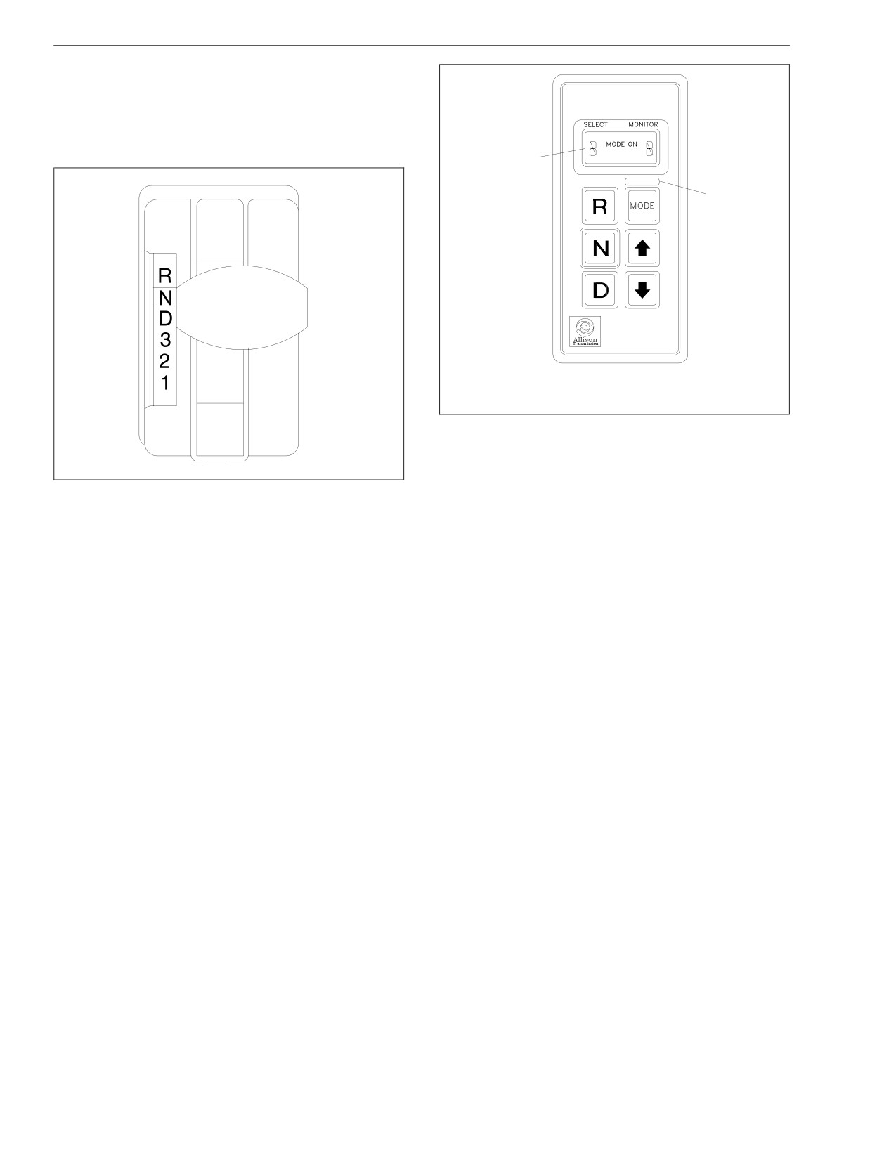
Transmissions
The MD-series transmission system is designed to warn
the driver of transmission malfunctions. The driver of a
vehicle equipped with one of these transmissions
should know the extent of the warning system in order
to safely operate the vehicle. See Chapter 2 for infor-
mation on the warning system.
1
2
10/31/94
f600369a
1. Digital Display
2. Mode Identification
Fig. 5.4, Allison Push-Button Shift Selector
Operation
07/09/96
f270004
IMPORTANT: Do not race the engine when shifting
Fig. 5.3, Shift Indicator Lever
from Neutral (N) into a Drive (D) gear range.
5.3
Transmissions
1. Use Reverse (R) to back the vehicle. Completely
for climbing long grades and for engine braking
stop the vehicle before shifting from a forward gear
when descending moderately steep grades. To pre-
to Reverse (R) or from Reverse (R) to a forward
vent excessive engine speed, do not drive faster
gear. There is only one Reverse (R) gear.
than 45 miles per hour (72 km/h) in Second (2) or
Third (3).
2. Use Neutral (N) and set the parking brake to park
the vehicle with the engine running or shut down.
5. Use First (1) for climbing very steep grades and for
The engine may be started in this position. Always
engine braking at low speeds when going downhill.
chock the tires for hilly or off-road parking.
To prevent excessive engine speed, do not drive
faster than 25 miles per hour (40 km/h) in First (1).
CAUTION
NOTE: In the lower gear ranges, the transmission
will not upshift above the highest gear selected
Do not allow the vehicle to coast in neutral. This
unless the engine governed speed is exceeded.
can result in severe transmission damage. Also, no
engine braking is available.
MD-Series Transmissions
3. Select Drive (D) for all normal driving conditions.
The vehicle will start out in First (1) gear, and as
CAUTION
speed increases, the transmission will upshift
through each gear automatically. As the vehicle
The engine should never be operated for more than
slows down, the transmission will downshift to the
30 seconds at full throttle with the transmission in
correct gear automatically.
gear and the output stalled. Prolonged operation of
this type will overheat the transmission fluid and
Occasionally the road, load, or traffic conditions
will result in severe damage to the transmission.
make it desirable to restrict the automatic shifting to
a lower range. The lower the gear range, the
1. Start the engine, then check the digital display on
greater the engine braking power.
the push-button shift selector. Under Select at the
top of the unit, the display shows the primary shift
4. Use Second (2) or Third (3) for slow driving in
mode. Under Monitor, the gear that is engaged is
heavy city traffic, or on mountain roads when more
displayed.
precise speed control is desirable. Use them also
5.4
Transmissions
Use the UP or DOWN arrow buttons on the shift
WARNING
selector to reach the desired gear. The Select indi-
cator will display your choice, and the Monitor indi-
Never shift from neutral (N) to drive (D) or reverse
cator will show the selected gear once it is reached.
(R) at engine speeds above idle. The vehicle will
NOTE: In the lower gear ranges, the transmission
lurch forward or backward, which could cause prop-
erty damage and personal injury.
will not upshift above the highest gear selected
unless the engine governed speed is exceeded.
2. Use Reverse (R) to back the vehicle. Completely
stop the vehicle before shifting from a forward gear
5. Engage Neutral (N) and apply the parking brake
to Reverse (R) or from Reverse (R) to a forward
when the vehicle is parked with the engine running.
gear. There is only one Reverse (R) gear.
3. Select Drive (D) for all normal driving conditions.
CAUTION
The vehicle will start out in First (1) gear, and as
speed increases, the transmission will upshift
Do not allow the vehicle to coast in neutral. This
through each gear automatically. As the vehicle
can result in severe transmission damage. Also, no
slows down, the transmission will downshift to the
engine braking is available.
correct gear automatically.
Safety Precautions
The pressure of your foot on the accelerator pedal
Do the following steps if you have to leave the cab with
influences the automatic shifting. When the pedal is
the engine running (for example, when checking the
fully depressed, the transmission will automatically
transmission fluid):
upshift near the governed speed of the engine. A
partially depressed position of the pedal will cause
1. Bring the vehicle to a complete stop using the ser-
the upshifts to occur at a lower engine speed.
vice brakes.
4. Occasionally the road, load, or traffic conditions
2. Put the transmission in Neutral (N).
make it desirable to restrict the automatic shifting to
3. Ensure that the engine is at low idle rpm (below
a lower range. The lower the gear range, the
1000).
greater the engine braking power.
5.5
Transmissions
4. Apply the parking brake and the emergency brake,
and make sure that they are properly engaged.
5. Chock the rear tires and take any other steps nec-
essary to keep the vehicle from moving.
5.6
6
Steering System
General Information
6.1
Power Steering System
6.1
Tilt/Telescope Steering Column (optional)
6.2
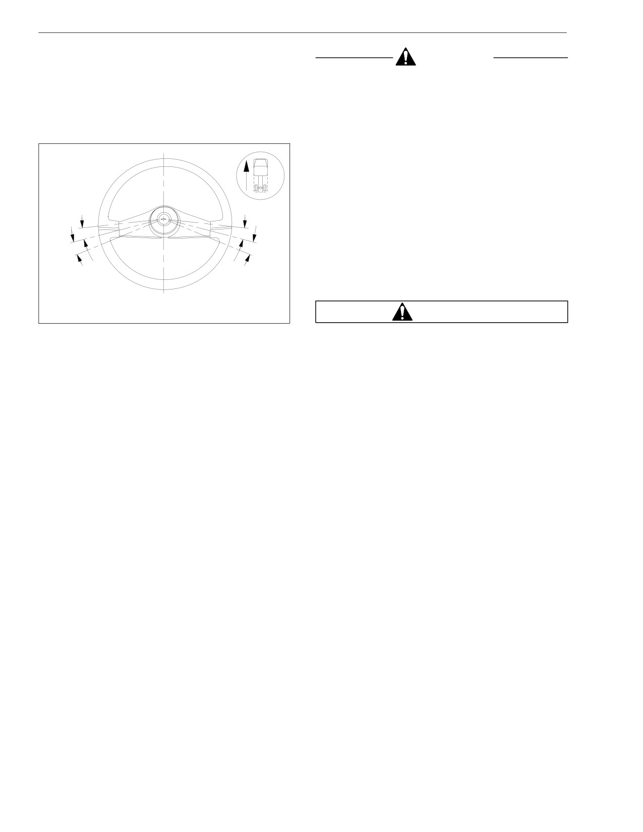
Steering System
General Information
CAUTION
When there is no load on the vehicle, and the front tires
are pointed straight ahead, the steering wheel spokes
Never steam clean or high-pressure wash the steer-
should be at the 9 and 3 o’clock positions, or within 10
ing gear. Internal damage to gear seals and ulti-
degrees to either side. See Fig. 6.1. See Group 46 of
mately the steering gear can result.
the School Bus Chassis Workshop Manual for steering
adjustment procedures.
Power Steering System
The power steering system consists of a steering gear
(which includes a manual steering mechanism, a hy-
draulic control valve, and a hydraulic power cylinder),
hydraulic hoses, power steering pump, reservoir, and
other components. The power steering pump, driven by
the engine, provides the power assist for the steering
system. If the engine is not running, there is no power
10°
10°
assist.
1
2
If the power-assist feature does not work due to hydrau-
lic fluid loss, steering pump damage, or some other
10°
10°
cause, bring the vehicle to a safe stop. Do not drive the
vehicle until the cause of the problem has been cor-
rected.
11/15/2000
f460307b
1.
9 o’Clock
2.
3 o’Clock
WARNING
Fig. 6.1, Steering Wheel Centered
Driving the vehicle without the power-assist feature
of the steering system requires much greater effort,
especially in sharp turns or at low speeds, which
could result in an accident and possible injury.
6.1
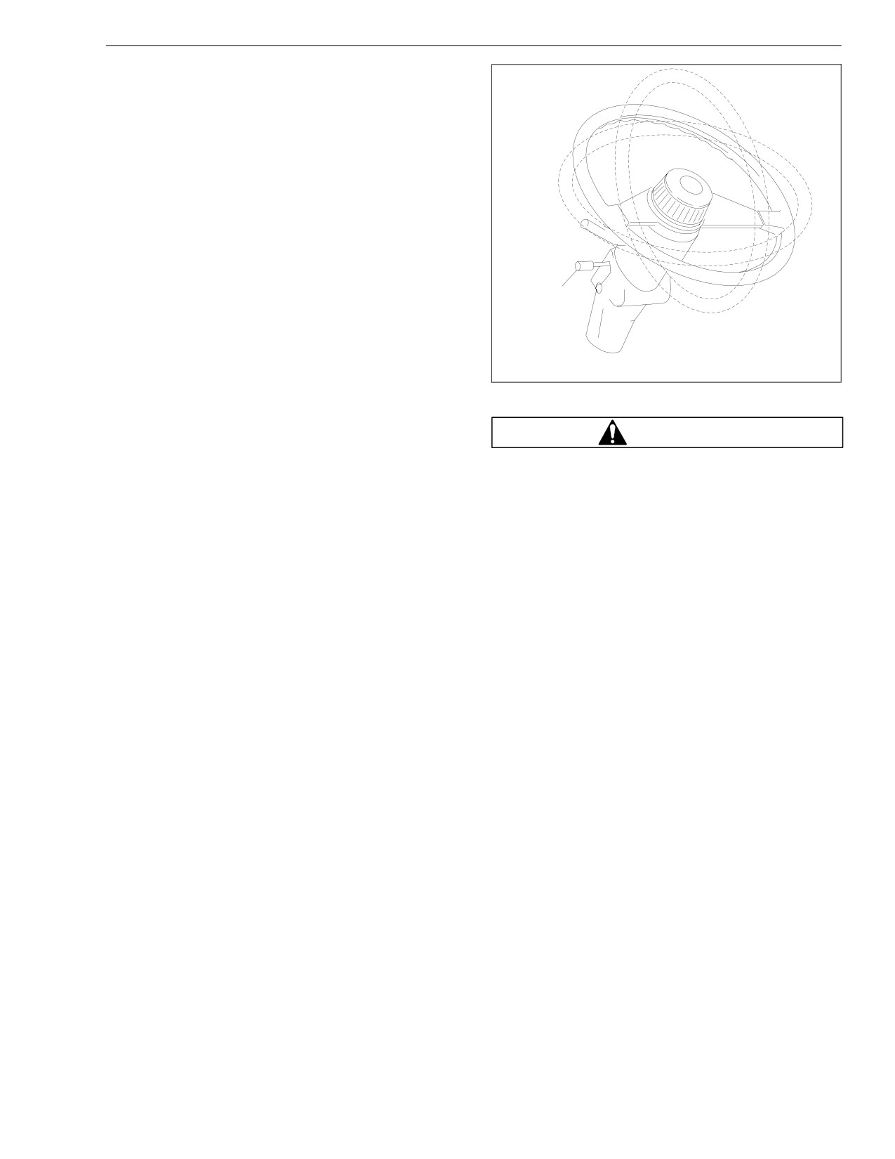
Steering System
Drivers should use the power available with a power
steering system carefully. If the front tires become
lodged in a deep chuckhole or rut, drive the vehicle out
instead of using the steering system to lift the tires from
the hole. Also avoid turning the tires when they are
against a curb, as this places a heavy load on steering
components and could damage them.
Tilt/Telescope Steering Column
(optional)
Adjust the seat to a comfortable position. If the vehicle
is equipped with a tilt/telescope steering column, pull
the control lever on the column upward and adjust the
1
steering wheel to the desired position. See Fig. 6.2.
Push the lever downward and extend or retract the
steering column as desired. Release the control lever to
lock the steering column in place.
11/15/2000
f461176a
If the vehicle is equipped with a tilt-only column, adjust
1. Tilt/Telescope Lever
the steering wheel with either a control lever on the col-
umn or a foot-operated control valve located to the left
Fig. 6.2, Tilt/Telescope Steering Column
of the clutch or brake pedal. See Fig. 6.3. Release the
control lever or valve to lock the steering column in
WARNING
place.
Make sure that the control lever or valve is released
and that the steering column is locked before driv-
ing the vehicle. Never tilt or telescope the column
while driving the vehicle. Doing so could cause loss
6.2
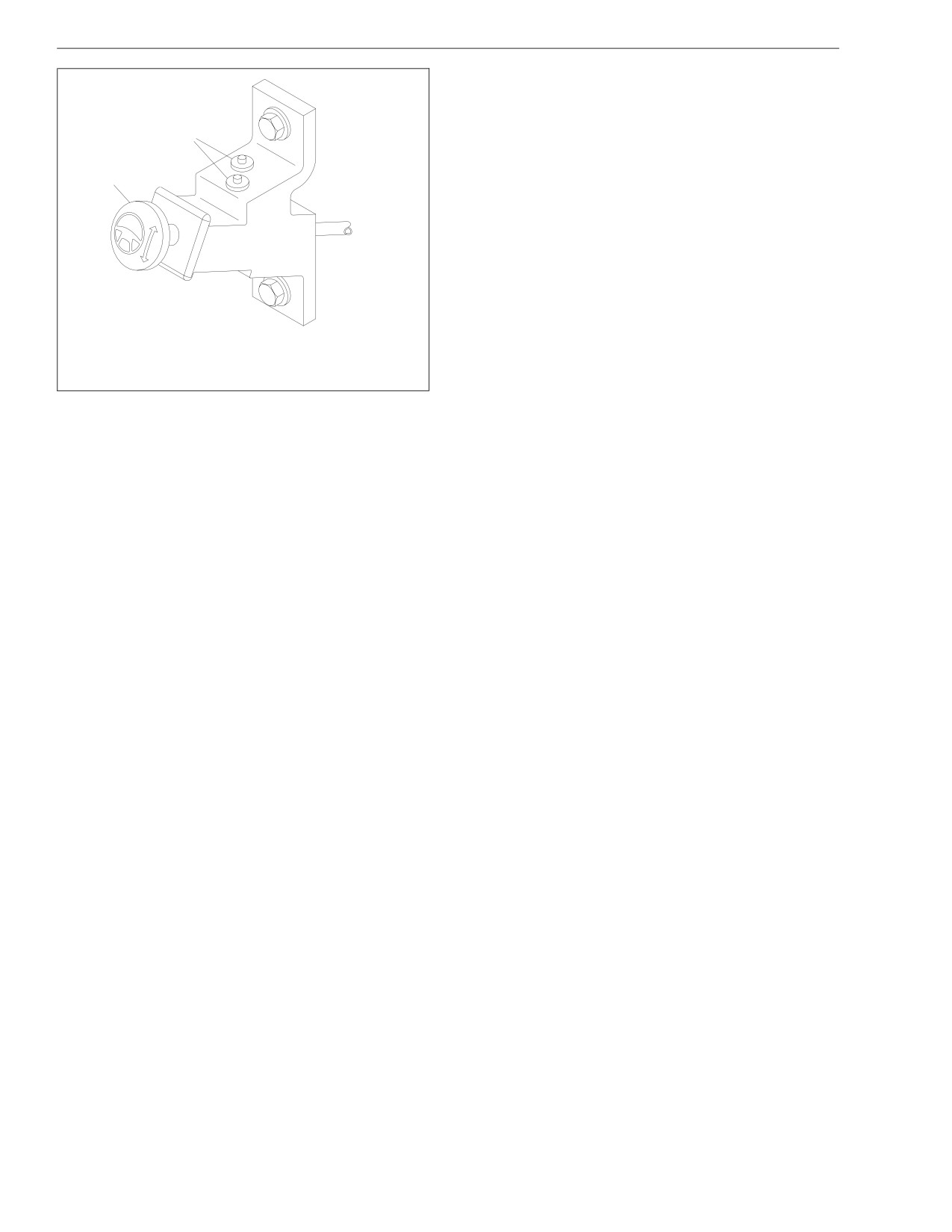
Steering System
2
1
04/05/2002
f461234a
1. Adjustment Valve Knob (yellow)
2. Air Line Connections
Fig. 6.3, Foot-Operated Tilt Column Control Valve
of vehicle control, personal injury, and property
damage.
6.3
7
Brake System
Driveline Parking Brake Burnishing
7.1
Hydraulic Brake System
7.1
Air Brake System
7.4
Brake System
4. Adjust the parking brake linkage and hand lever
Driveline Parking Brake
knob to suit your load and road grade conditions.
Burnishing
Hydraulic Brake System
WARNING
General Information
Vehicles equipped with hydraulic brakes are
The Bendix hydraulic brake system includes a power
equipped with a driveline parking brake. If your ve-
booster, master cylinder, reservoir , hydraulic lines, a
hicle is equipped with a driveline parking brake, you
brake rotor on each wheel hub, and a brake caliper and
must burnish the parking brake before you put the
pad assembly at each rotor. See Fig. 7.1.
vehicle into regular service. An unburnished park-
ing brake may not have full effectiveness. If the
IMPORTANT: Make sure that the fluid level in the
parking brake slips, personal injury or property
master cylinder reservoir is up to the ridge that
damage could result.
surrounds the reservoir. Use only heavy-duty
brake fluid, DOT 3, in the hydraulic brake system.
Burnish the driveline parking brake as follows:
The master cylinder controls braking power to the front
1. Load the vehicle to its gross vehicle weight (GVW).
and rear brakes. The power booster is attached to the
2. With the parking brake released, turn the knob on
rear of the master cylinder and is connected to the
the end of the parking brake handle clockwise to
power steering system (which provides pressurized
adjust the parking brake. Adjust the brakes until you
power steering fluid). An electrically-powered "reserve"
can stop the vehicle traveling at 10 mph (16 km/h)
pump operates if there is inadequate fluid flow from the
within stopping distances of 21 to 36 feet (8 to 11
power steering pump to the power booster. The brake
m) using only the parking brake.
system warning light comes on if there is a problem
within the system. Bring the vehicle to a safe stop and
3. Using only the parking brake, make 10 stops from
correct the problem before continuing operation of the
10 mph (16 km/h) on a hard dry road surface. After
vehicle. See Group 42 of the School Bus Chassis
each stop, release the parking brake and drive the
Workshop Manual for hydraulic brake system trouble-
vehicle at 20 mph (32 km/h) for 2.5 miles (4 km) to
shooting and adjustment procedures.
cool the brake.
7.1
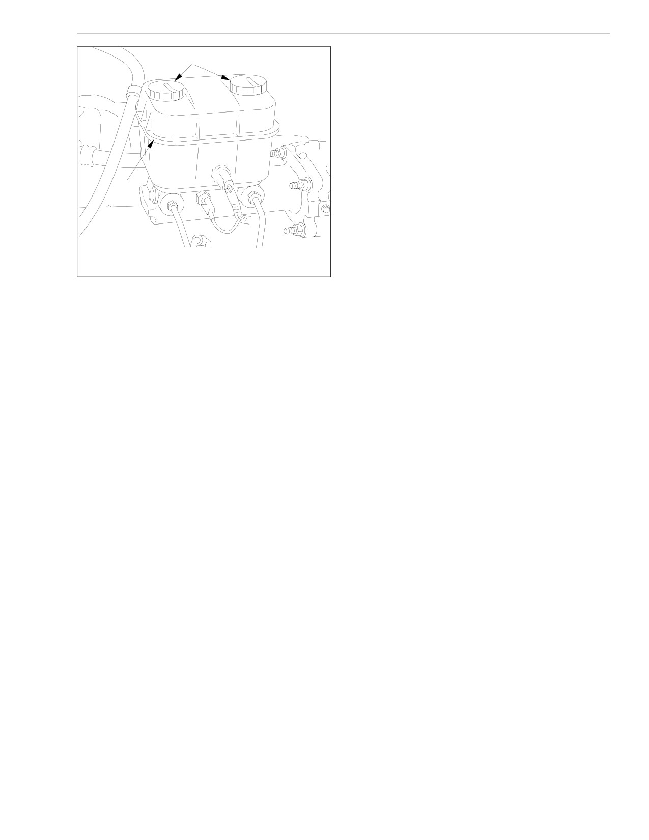
Brake System
does not go out, correct the problem before continuing
A
operation of the vehicle.
During normal brake stops, depress the foot brake con-
trol pedal until braking action slows the vehicle. In-
crease or decrease the pressure on the pedal so that
the vehicle comes to a smooth, safe stop. When the
forward speed of the vehicle has decreased to almost
the idling speed of the engine, push the clutch pedal in
(if so equipped), and shift the transmission into Neutral
(N). Apply the hand parking brake if the vehicle is to be
parked.
B
Meritor WABCO® Antilock Braking
System (ABS), Hydraulic Brake
Systems
10/31/94
f460513a
The Meritor WABCO® Antilock Braking System (ABS) is
an electronic wheel speed monitoring and control sys-
A. Open caps and check fluid level.
tem that works with the hydraulic brake system. ABS
B. Fill to this level.
passively monitors vehicle wheel speed at all times, but
Fig. 7.1, Hydraulic Brake Reservoir
controls wheel speed during an emergency or reduced-
traction stop. In normal braking applications, the stan-
dard hydraulic brake system is in effect.
Operation
Before driving the vehicle, secure all loose items in the
IMPORTANT: For proper ABS system operation,
cab so that they will not fly forward during a full brake
do not change tire sizes. The sizes of the tires in-
application. Check that the brake system warning light
stalled during production are programmed into the
is out after releasing the hand brake. If the warning light
electronic control unit. Installing different sized
7.2
Brake System
tires could result in inaccurate wheel speed sig-
and to protect the components from corrosion.
nals to the ECU resulting in reduced braking force,
Clean more frequently when unusually corrosive
chemicals are being used.
which could lead to longer stopping distances.
ABS includes signal-generating tone wheels and sen-
IMPORTANT: During winter months in areas where
sors located in the wheel hubs of each sensed axle.
corrosive materials are used on the highways, pe-
The sensors transmit vehicle wheel speed information
riodically clean the underside of the vehicle to en-
to an electronic control unit (located on the frontwall)
sure proper ABS functioning.
that interprets these signals to calculate wheel speed
The electronic control unit also has a safety circuit that
and a vehicle reference speed. If the calculations indi-
constantly monitors the wheel sensors, brake pressure
cate wheel lockup, the appropriate control circuit signals
modulator, and the electrical circuitry. The dash warning
the brake pressure modulator to increase or decrease
light (ABS) comes on after the ignition switch is turned
braking pressure until wheelslip has been corrected.
to the ON position. Once the vehicle moves faster than
about 4 mph (6 km/h), the warning light goes out only if
CAUTION
all of the vehicle’s ABS components are working.
If, during vehicle operation, the safety circuit senses a
An accumulation of road salt, dirt, or debris on the
failure in any part of the ABS system (a sensor, brake
ABS tone wheels and sensors can cause the ABS
pressure modulator, wiring connection, short circuit,
warning light to come on. If the ABS light does
etc.), the warning light (ABS) comes on and the control
come on, the tone rings and sensors should be in-
circuit where the failure occurred is switched to normal
spected for corrosion and serviced if necessary.
braking action. Even if the ABS system is partially or
The service should include cleaning of the tone
completely inoperative, normal braking ability is main-
rings and sensors. If any tone ring on a vehicle
tained. An exception would be if the brake pressure
shows severe corrosion, all tone rings on that ve-
modulator, or hydraulic fluid line is damaged. As these
hicle should be replaced.
components are an integral part of the hydraulic brake
During winter months in areas where corrosive ma-
system, normal braking may be impaired or inoperative.
terials are used on the highways, periodically clean
IMPORTANT: If any of the ABS warning lights do
the underside of the vehicle, including the tone
not work as described above, or come on while
rings and sensors, to ensure proper ABS function
7.3
Brake System
driving, repair the ABS system immediately to en-
WARNING
sure full antilock braking capability.
During emergency or reduced-traction stops, fully de-
Do not operate the vehicle with the front brakes
press the brake pedal until the vehicle comes to a safe
backed off or disconnected. Backing off or discon-
stop; do not pumpthe brake pedal. With the brake pedal
necting the front brakes will not improve vehicle
fully depressed, the ABS system will control all wheels
handling and may lead to loss of vehicle control
to provide steering control and a reduced braking dis-
resulting in property damage or personal injury.
tance.
Loss of air pressure in the primary system causes the
Although the ABS system improves vehicle control dur-
rear service brakes to become inoperative; front brakes
ing emergency braking situations, the driver still has the
will continue to be operated by secondary system air
responsibility to change driving styles depending on the
pressure.
existing traffic and road conditions. For example, the
ABS system cannot prevent an accident if the driver is
Loss of secondary system air pressure causes the front
axle brakes to become inoperative; rear service brakes
speeding or following too closely on slippery road sur-
faces.
will continue to be operated by the primary system.
Before driving your vehicle, allow time for the air com-
Air Brake System
pressor to build up a minimum of 95 psi (655 kPa) pres-
sure in both the primary and secondary systems. Moni-
General Information
tor the air pressure system by observing the dual
system air pressure gauges and the low-air-pressure
A dual air brake system consists of two independent air
warning light and buzzer. The warning light and buzzer
brake systems which use a single set of brake controls.
shut off when air pressure in both systems reaches 64
Each system has its own reservoir, plumbing, and brake
to 76 psi (441 to 524 kPa).
chambers. The primary system operates the service
brakes on the rear axle; the secondary system operates
The warning light and buzzer come on if air pressure
the service brakes on the front axle.
drops below 64 to 76 psi (441 to 524 kPa) in either sys-
tem. If this happens, check the air system pressure
7.4
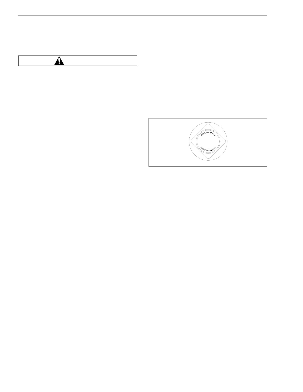
Brake System
gauges to determine which system has low air pres-
Operation
sure. Although the vehicle’s speed can be reduced us-
ing the foot brake control pedal, either the front or rear
Before driving the vehicle, secure all loose items in the
service brakes will not be operating, causing a longer
cab so that they will not fly forward during a full brake
stopping distance. Bring the vehicle to a safe stop, and
application.
have the air system repaired before continuing.
During normal brake stops, depress the foot brake con-
trol pedal until braking action slows the vehicle. In-
WARNING
crease or decrease the pressure on the pedal so that
the vehicle comes to a smooth, safe stop. When the
Do not drive the vehicle with the parking brakes
forward speed of the vehicle has decreased almost to
caged. If the vehicle is driven with the parking
the idling speed of the engine, push the clutch pedal in
brakes caged, there would be no means of stopping
(if so equipped), and shift the transmission into Neutral
the vehicle if a complete loss of air pressure oc-
(N). Apply the parking brake if the vehicle is to be
curred. This could result in serious personal injury
parked.
or vehicle damage. Before caging the spring park-
The yellow diamond-shaped knob on the control panel
ing brakes, make the connection to a towing vehicle
actuates the parking brake valve. See Fig. 7.2. Pull the
or chock the tires.
knob out to apply the parking brake.
NOTE: Before a vehicle with insufficient system air
pressure can be moved, the spring parking brakes
must be released by applying an external air
source, or by manually caging (manually releas-
ing) the parking brake springs.
SYSTEM
PARK
After correcting the brake system problem, uncage the
spring parking brakes before resuming normal vehicle
operation.
02/09/95
f600631
Fig. 7.2, Parking Brake Valve Knob
7.5
Brake System
Meritor WABCO® Antilock Braking
WARNING
System (ABS), Air Brake Systems
If the vehicle is equipped with an air suspension
The Meritor WABCO® Antilock Braking System (ABS) is
system, do not move the vehicle with the air sus-
an electronic wheel speed monitoring and control sys-
pension deflated. Doing so could result in a loss of
tem that works with the air brake system. ABS passively
vehicle control, possibly causing personal injury
monitors vehicle wheel speed at all times, but controls
and property damage.
wheel speed during an emergency or reduced-traction
stop. In normal braking applications, the standard air
CAUTION
brake system is in effect.
IMPORTANT: For proper ABS system operation,
Do not use the spring parking brakes if the service
do not change tire sizes. The sizes of the tires in-
brakes are hot, such as after descending a steep
stalled during production are programmed into the
grade. Also, do not use the spring parking brakes
electronic control unit. Installing different sized
during freezing temperatures if the service brakes
are wet. To do so could damage the brakes if hot, or
tires could result in a reduced braking force, lead-
cause them to freeze during cold weather.
ing to longer stopping distances.
If the brakes are wet, drive the vehicle in low gear
ABS includes signal-generating tone wheels and sen-
sors located in the wheel hubs of each sensed axle.
and lightly apply the brakes to heat and dry them.
Allow hot brakes to cool before using the spring
The sensors transmit vehicle wheel speed information
to an electronic control unit (located on the frontwall).
parking brakes. Always chock the tires.
The control unit’s main circuit interprets the speed sen-
If the brakes are wet, drive the vehicle in low gear and
sor signals and calculates wheel speed, wheel retarda-
lightly apply the brakes to heat and dry them.
tion, and a vehicle reference speed. If the calculations
Allow hot brakes to cool before using the parking brake.
indicate wheel lockup, the main circuit signals the ap-
Always chock the tires.
propriate solenoid control valve to reduce braking pres-
sure. During emergency braking, the solenoid control
valve alternately reduces, increases, or maintains air
7.6
Brake System
pressure supply in the brake chamber to prevent front
valves, and the electrical circuitry. The ABS warning
and rear wheel lockup.
light comes on after turning the ignition switch to the
ON position. Once the vehicle moves faster than about
4 mph (6 km/h), the warning light goes out only if all of
CAUTION
the ABS components are working.
An accumulation of road salt, dirt, or debris on the
The Meritor WABCO® ABS system combines one front-
ABS tone wheels and sensors can cause the ABS
axle control channel with the rear axle (the four-sensor
warning light to come on. If the ABS light does
system) to form one control circuit. For example, the
come on, the tone rings and sensors should be in-
sensor and solenoid control valve at the left-front axle
spected for corrosion and serviced if necessary.
form a control circuit with the sensor and solenoid valve
The service should include cleaning of the tone
on the right rear axle. If, during vehicle operation, the
rings and sensors. If any tone ring on a vehicle
safety circuit senses a failure in any part of the ABS
shows severe corrosion, all tone rings on that ve-
system (a sensor, solenoid control valve, wiring connec-
hicle should be replaced.
tion, short circuit, etc.), the warning light (ABS) comes
on and the control circuit where the failure occurred is
During winter months in areas where corrosive ma-
switched to normal braking action. The remaining con-
terials are used on the highways, periodically clean
trol circuit will retain the ABS effect. Even if the ABS
the underside of the vehicle, including the tone
system is partially or completely inoperative, normal
rings and sensors, to ensure proper ABS function
braking ability is maintained. An exception would be if a
and to protect the components from corrosion.
solenoid control valve (or combination solenoid control
Clean more frequently when unusually corrosive
valve) is damaged and inoperative. As these compo-
chemicals are being used.
nents are an integral part of the air brake system, nor-
mal braking may be impaired or inoperative.
IMPORTANT: During winter months in areas where
corrosive materials are used on the highways, pe-
IMPORTANT: If any of the ABS warning lights do
riodically clean the underside of the vehicle to en-
not work as described above, or come on while
sure proper ABS functioning.
driving, repair the ABS system immediately to en-
The electronic control unit also has a safety circuit that
sure full antilock braking capability.
constantly monitors the wheel sensors, solenoid control
7.7
Brake System
During emergency or reduced-traction stops, fully de-
press the brake pedal until the vehicle comes to a safe
WARNING
stop; do not pumpthe brake pedal. With the brake pedal
fully depressed, the ABS system will control all wheels
Manually adjusting an automatic slack adjuster to
to provide steering control and a reduced braking dis-
bring the pushrod stroke within legal limits is likely
tance.
masking a mechanical problem. Adjustment is not
repairing. In fact, continual adjustment of automatic
Although the ABS system improves vehicle control dur-
slack adjusters may result in premature wear of the
ing emergency braking situations, the driver still has the
adjuster itself. Further, the improper adjustment of
responsibility to change driving styles depending on the
some automatic slack adjusters may cause internal
existing traffic and road conditions. For example, the
damage to the adjuster, thereby preventing it from
ABS system cannot prevent an accident if the driver is
properly functioning.
speeding or following too closely on slippery road
surfaces.
Automatic Slack Adjusters
Automatic slack adjusters are required on all vehicles
equipped with air brakes manufactured after October
20, 1994. Automatic slack adjusters should never be
manually adjusted except during routine maintenance of
the foundation brakes (e.g., replacing shoes), during
slack adjuster installation or in an emergency situation.
When the brake pushrod stroke exceeds the legal brake
adjustment limit on a vehicle, there is likely a mechani-
cal problem with the foundation brake components or
the adjuster is improperly installed.
Visit a repair facility as soon as possible when brakes
equipped with automatic slack adjusters are determined
to be out of adjustment.
7.8
8
Pretrip Inspection and Daily
Maintenance
Pretrip Inspection Checklist
8.1
Pretrip Inspection and Daily Maintenance Procedures
8.3
Pretrip Inspection and Daily Maintenance
inspections save time by eliminating stops later to ad-
Pretrip Inspection Checklist
just items overlooked or forgotten.
IMPORTANT: If the vehicle is taken out of service
Each checklist step corresponds with detailed instruc-
for an extended period of time (such as for the
tions found under "Pretrip Inspection and Daily Mainte-
Summer) follow the procedures below.
nance Procedures." If any system or component does
not pass this inspection, it must be corrected before
• In regions where corrosive materials are applied
operating the vehicle. See the School Bus Chassis
to roads and highways to control ice, thoroughly
Workshop Manual for repair procedures, and the School
clean the underside of the vehicle to prevent cor-
Bus Chassis Maintenance Manual for lubricant recom-
rosion.
mendations, specifications, and maintenance intervals
• Ensure that the vehicle is not parked over dry
and procedures.
brush or leaves. This is a potential fire hazard.
NOTE: Apply the parking brakes and chock the
• Disconnect the batteries and charge them peri-
tires.
odically using a trickle charger.
1. Drain the air brake system air reservoirs, if so
• Approximately once a month, connect the batter-
equipped.
ies, start the vehicle, and allow the engine to
reach normal operating temperature.
2. Inspect the batteries and battery cables.
• Once the engine reaches normal operating tem-
3. Check the fluid level in the windshield washer res-
perature, lubricate the radiator shutters. This will
ervoir.
prevent them from seizing.
4. Check the front hub lubricant level (if equipped with
The following pretrip inspection checklist helps ensure
oil-lubricated wheel bearings).
that the vehicle components are in good working condi-
5. Tilt the hood. Examine the steering components.
tion before each trip.
6. Check the coolant level in the surge tank sight
Pretrip inspections cannot be performed in a short pe-
glass and check the radiator and the charge air
riod. In checklist form, the sequence below may seem
cooler for clogging or damage. Check the radiator
to be overly time-consuming. However, careful pretrip
for coolant leaks.
8.1
Pretrip Inspection and Daily Maintenance
7.
Check the condition and operation of the engine
check the fuel/water separator for leaks. If needed,
radiator shutters.
prime the fuel system.
8.
Check the condition of the coolant hoses and
20.
Inspect the front and rear suspension components,
heater hoses.
including the springs and air springs, shocks, and
suspension brackets.
9.
Check the condition of the drive belts.
21.
Check for excessive play at the steering wheel.
10.
Inspect the engine for fuel, oil, and coolant leaks.
22.
On mechanical clutch linkages (if so equipped),
11.
Inspect the engine and chassis wiring.
check the clutch pedal free-travel.
12.
Inspect the air intake system for leaks or damage.
23.
Turn the ignition switch to the ON position and start
Check the intake-air restriction indicator if it is
the engine. Be sure that the oil pressure warning
mounted on the air intake system.
system is operating. Leave the engine running.
13.
Check the fluid level in the hydraulic brake fluid res-
24.
Make sure that the electric horn is operating prop-
ervoir, if so equipped.
erly.
14.
Check the engine lubricating oil level.
25.
Make sure that all of the lights are working, includ-
15.
Check the oil level in the automatic transmission, if
ing the brake lights, high and low beam headlights,
so equipped.
turn signals, clearance lights, and emergency flash-
ers. Check the condition of the reflectors. Turn the
16.
Check the fuel water separator (if so equipped) for
lights off. Shut down the engine.
contaminants.
26.
Inspect the air brake components (if so equipped)
17.
Close the hood and engage the hood hold-down
including the brake chamber pushrods, air reser-
latches.
voirs, and air lines.
18.
Inspect the fuel tank(s) and fuel line connections. If
27.
Check the brake lining wear (if equipped with air
so equipped, be sure that the fuel tank shutoff
brakes).
valves are open.
28.
Make sure that the brakes are adjusted on all ax-
19.
Check the fuel level in the fuel tank(s) and be sure
les.
that the fuel cap vent area is clean. If so equipped,
8.2
Pretrip Inspection and Daily Maintenance
29. Check the tire inflation pressures and inspect each
After the water and oil condense, they collect near
tire for bulges, cracks, cuts, and punctures.
the tank drain valves. Drain the resulting emulsion
as follows:
30. Check for indications of loose wheel nuts or rim
nuts and examine each rim and wheel component.
WARNING
31. Check the air brake system for proper operation.
32. Test the service brakes before leaving the lot.
Failure to drain the air reservoirs as instructed
could cause sludge formation in the air brake sys-
33. Test the parking brakes on a 20-percent grade.
tem. Sludge could adversely affect braking, causing
loss of control, which could cause death, personal
Pretrip Inspection and Daily
injury, or property damage.
Maintenance Procedures
IMPORTANT: If the air tanks are not equipped
Whenever equipment requires adjustment, replacement,
with automatic drain valves, they must be
repair, addition of lubricants, or a change of lubricants,
drained daily. If they are equipped with auto-
see the School Bus Chassis Workshop Manual for re-
matic drain valves, they must be drained in
pair procedures and specifications. See the School Bus
this same manner at least once a week.
Chassis Maintenance Manual for lubricant recommen-
1.1
Open the wet tank valve (the drain cock or
dations, specifications, and maintenance intervals and
pull-chain drain located on the forward end
procedures.
of the supply air reservoir, which is con-
1. Drain the air brake system air reservoirs, if so
nected directly to the air compressor). Block
equipped.
the valve open.
Air reservoirs serve as storage tanks for com-
pressed air. They collect water condensed from the
WARNING
air and small amounts of oil from the air compres-
sor. Water and oil normally enter the reservoir in
When draining the air reservoir, do not look into the
the form of vapor because of the heat generated
air jets or direct them toward anyone. Dirt or sludge
during compression.
8.3
Pretrip Inspection and Daily Maintenance
particles may be in the airstream and could cause
injury.
CAUTION
1.2
Exhaust the remaining air and moisture from
Take care to keep the vent plugs tight so that the
the system by opening the drain cocks on
neutralizing solution does not enter any of the bat-
the bottoms of the remaining air reservoirs.
tery cells and damage the battery.
Block the valves open.
2.2
Remove any corrosion from the hold down
1.3
Water and oil emulsion often forms pockets
and the top of the battery. Use diluted am-
which will not drain while compressed air is
monia or a soda solution to neutralize the
in the reservoirs. Because of these pockets,
acid present, then rinse off the ammonia or
leave the valves blocked open during the
soda solution with clean water.
first part of the pretrip inspection.
If the battery posts or cable terminals are
2. Inspect the batteries and battery cables as follows:
corroded, disconnect the terminals from the
posts. Clean them with a soda solution and
WARNING
a wire brush. After cleaning, connect the ter-
minals to the battery posts, then apply a thin
Battery posts, terminals, and related accessories
coat of petroleum jelly to the posts and ter-
contain lead and lead compounds, chemicals
minals to help retard corrosion.
known to the State of California to cause cancer
3. Check the fluid level in the windshield washer res-
and reproductive harm. To prevent possible per-
ervoir.
sonal injury, always wash your hands after handling
battery parts and related accessories.
Tilt the hood to access the reservoir (located next
2.1
Access the batteries. Be sure that the bat-
to the surge tank). Add washer fluid as needed.
tery hold down is secure. If it is loose,
See Fig. 8.1.
tighten the hold-down bolts; if it is broken,
replace it.
8.4
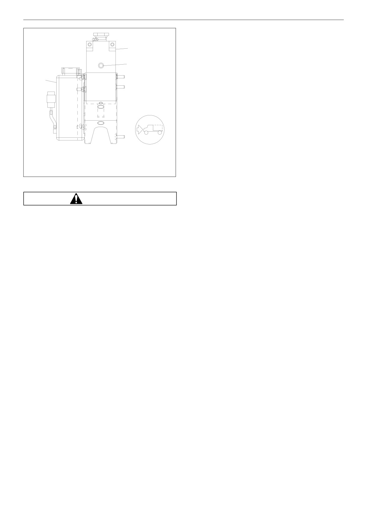
Pretrip Inspection and Daily Maintenance
burning material, such as a cigarette. Always com-
ply with the washer fluid manufacturer’s recom-
mended safety precautions.
2
4. Check the front hub lubricant level (if equipped with
oil-lubricated wheel bearings).
3
Observe the level of the wheel bearing lubricant in
the hub cap at each end of the front axle and, if
1
needed, fill the hubs to the level indicated on the
hub cap. See Group 33 of the School Bus Chassis
Maintenance Manual for recommended lubricants.
IMPORTANT: Before removing the fill plug, always
clean the hub cap and plug.
5. Tilt the hood. Examine the steering components.
Examine the steering gear mounting bolts, pitman
arm nut, and the drag link nuts for tightness. See
07/30/96
f500273
Fig. 8.2. Be sure that the steering driveline and the
1. Windshield Washer Reservoir
U-joints are in roadworthy condition, without cracks,
2. Surge Tank
breaks, looseness, or other damage. Tighten loose
3. Sight Glass
nuts, and replace damaged parts as needed. For
instructions, see Group 46 of the School Bus
Fig. 8.1, Check the Surge Tank Fluid Level
Chassis Workshop Manual.
WARNING
Washer fluids may be flammable and poisonous. Do
not expose washer fluid to an open flame or any
8.5
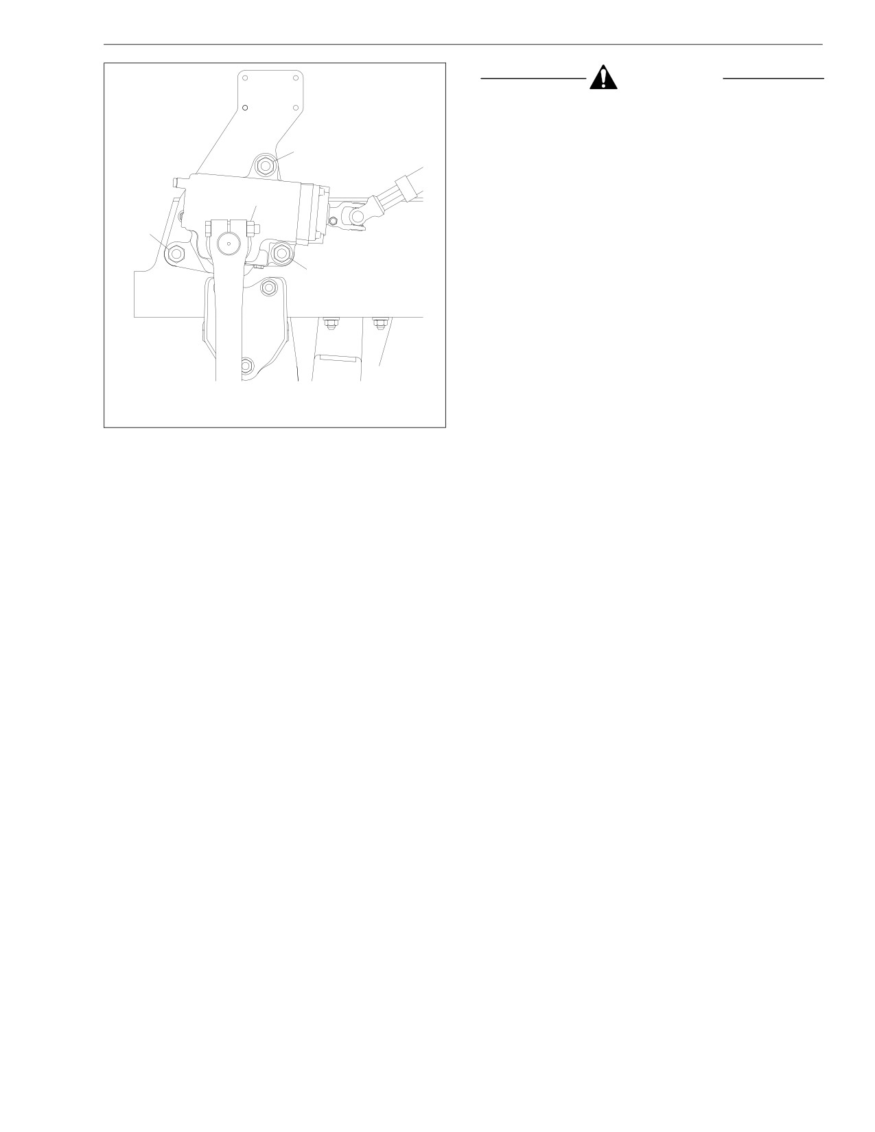
Pretrip Inspection and Daily Maintenance
CAUTION
Coolant must be filled to the full line of the surge
tank. Low coolant could result in engine overheat-
ing, which could cause engine damage.
1
6. Check the coolant level in the surge tank sight
glass. See Fig. 8.1. Check the condition of the ra-
diator fins and the charge air cooler.
2
If the coolant level is low, check the amount of anti-
1
freeze protection. If the protection is adequate, add
a 50/50 mixture of water and antifreeze. If addi-
tional protection is needed, add antifreeze only. Fill
1
to the level of the bottom of the surge tank fill neck.
Good airflow through the radiator core and air-to-air
aftercooler core is essential for proper engine cool-
ing. The cores allow air passage, but form a particle
barrier which tends to collect insects and airborne
debris.
10/05/94
f460512b
Inspect for clogged fins. Use compressed air or wa-
1. Steering Gear Mounting Bolt
ter directed from the fan side of the core to back-
2. Pitman Arm Pinch Bolt Nut
flush any material restricting airflow.
Fig. 8.2, Steering Gear (TAS series)
Inspect and clean the charge air cooler. If clogged,
the airflow through the radiator could be restricted.
Straighten bent or damaged fins to permit airflow
across all areas of the cores.
8.6
Pretrip Inspection and Daily Maintenance
Repair or replace the radiator if it is leaking. See
Tighten hose clamps as necessary, but do not over-
Group 20 of the School Bus Chassis Workshop
tighten as hose life can be adversely affected.
Manual for instructions.
Be sure that the hose support brackets are securely
NOTE: When traveling through areas of high in-
fastened. Make sure that the hoses are not located
sect concentrations, it may be necessary to clean
near sources of wear, abrasion, or high heat.
the exterior of the radiator or aftercooler core as
9. Check the condition of the drive belts.
often as every 200 miles (320 km).
Check the fan belt(s) and the alternator belt for
7. Check the condition and operation of the engine
signs of glazing, wear (frayed edges), damage
radiator shutters.
(breaks or cracks), or oil contamination. If a belt is
glazed, worn, damaged, or oil soaked, replace the
Inspect both pneumatic- and hydraulic-type engine
belt following the instructions in Group 01 of the
radiator shutters and ensure that they are free of
School Bus Chassis Workshop Manual.
contaminants and corrosion and operate properly.
8. Check the condition of the coolant hoses and
Check all of the belts for proper tension. See
heater hoses.
Group 01 of the School Bus Chassis Workshop
Manual for instructions.
Make sure that the radiator inlet and outlet coolant
hoses and heater hoses are pliable and are not
NOTE: On Cummins engines, a belt tensioner au-
cracking or ballooning. Replace hoses that show
tomatically adjusts the fan and alternator belt to
signs of cracking, weakening, or ballooning. Re-
the correct tension. If the belt slips, repair or re-
place all hoses, including heater hoses, at the
place the tensioner. For instructions, see the Cum-
same time. Service-type knitted or braided yarn-
mins Engine Operation and Maintenance Manual.
reinforced neoprene hose is acceptable.
10. Inspect the engine for fuel, oil, and coolant leaks.
Silicone hoses, having an extended service life, can
Correct any leaks found.
be substituted for the reinforced neoprene type.
See the Service Parts Catalog or contact your
11. Inspect the engine and chassis wiring.
dealer.
8.7
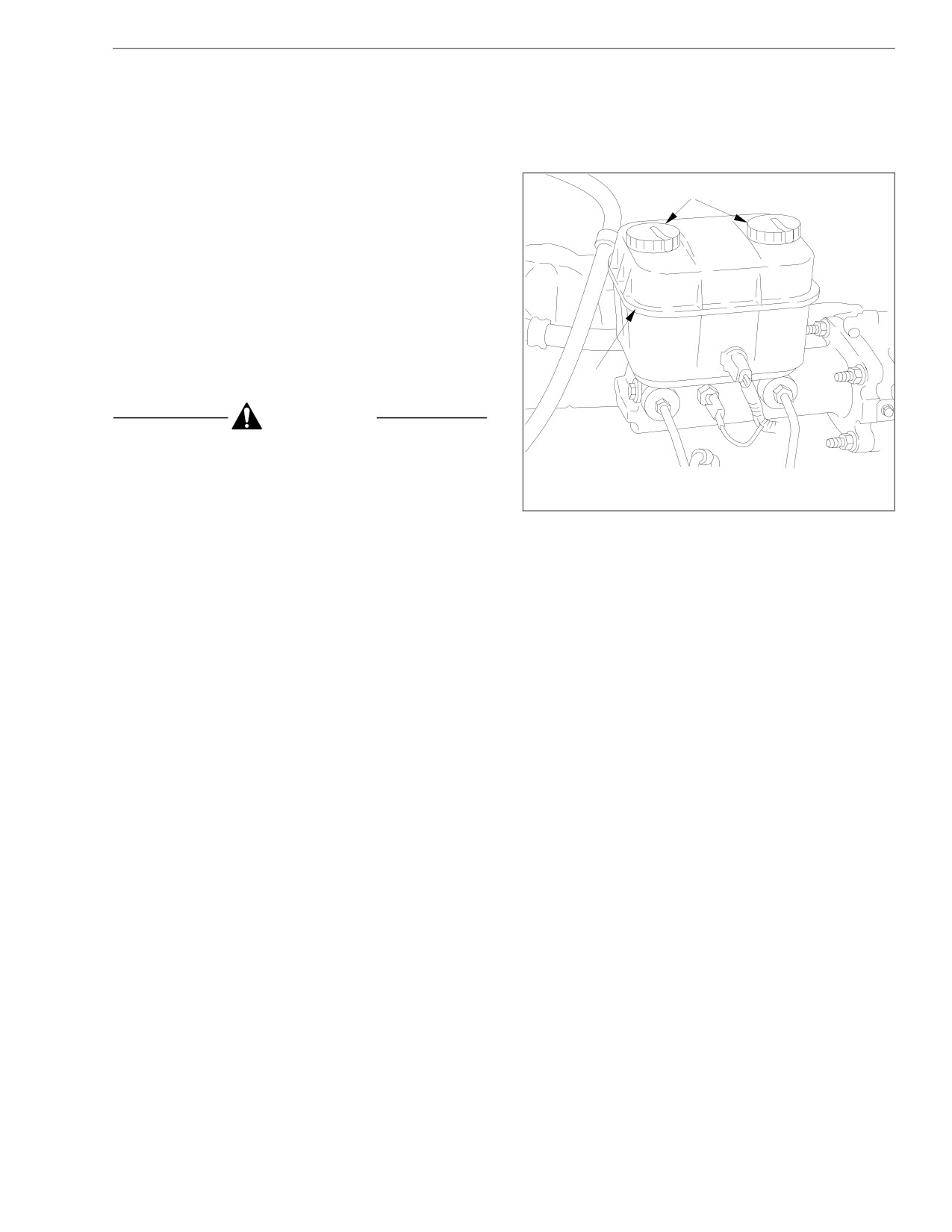
Pretrip Inspection and Daily Maintenance
Inspect the engine and chassis for loose wiring,
13. Check the fluid level in the hydraulic brake fluid res-
chafed insulation, and damaged or loose hold-down
ervoir, if so equipped. See Fig. 8.3.
clamps. Tighten loose wires or hold-down clamps;
If needed, fill the reservoir up to the ridge that sur-
replace damaged wiring or clamps.
rounds the reservoir. Use only heavy-duty brake
12. Check the air intake system for leaks or damage.
fluid, DOT 3.
Check the intake-air restriction indicator to deter-
mine if the air cleaner filter element needs to be
A
changed. Replace the filter element if the yellow
signal stays locked at 25 inH20. See Group 09 of
the School Bus Chassis Workshop Manual for filter
element replacement instructions.
Check the engine air intake piping from the air
cleaner to the engine intake. Inspect the piping for
loose connections, cracks, torn or collapsed hoses,
punctures, and other damage. Tighten loose con-
nections and replace damaged components. Make
sure that the piping system is airtight so that all of
the intake air passes through the air cleaner.
B
CAUTION
Failure to maintain a sealed air intake system could
10/31/94
f460513a
allow the entry of dirt and contaminants into the
A. Open caps and check fluid level.
engine. This could adversely affect engine perfor-
B. Fill to this level.
mance and result in engine damage.
Fig. 8.3, Check the Hydraulic Brake Fluid Level
NOTE: After replacing the filter element, reset the
restriction indicator by pressing the reset button.
8.8
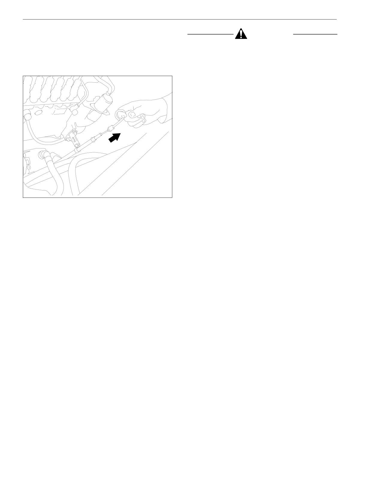
Pretrip Inspection and Daily Maintenance
14.
Check the engine oil level. See Fig. 8.4.
CAUTION
The oil level should show between the upper and
lower marks on the dipstick. Add enough oil to bring
Operating the engine with the oil level below the
the level up to the operating range. See the engine
low mark or above the high mark could result in en-
manufacturer’s Operation and Maintenance Manual
gine damage.
for recommended lubricants and capacities.
15. Check the oil level in the automatic transmission, if
so equipped.
NOTE: The fluid must be warm to ensure an accu-
rate check. The fluid level rises as temperature in-
creases.
With the vehicle on a level surface, check the oil
level (the dipstick is next to the windshield washer
reservoir) in the transmission using one of the fol-
lowing procedures:
Hot Check
• Operate the transmission in a Drive (D)
range until normal operating temperature,
160 to 200°F (71 to 93°C), is reached.
• Park the vehicle. Shift to Neutral (N) and ap-
ply the parking brake. Let the engine run at
idle.
f010346
• Wipe the dipstick clean and check the fluid
Fig. 8.4, Check the Engine Oil Level
level. A safe operating level is any level
within the HOT run (upper) band on the dip-
stick. See Fig. 8.5.
8.9

Pretrip Inspection and Daily Maintenance
• If the fluid is not within this range, add or
• With the engine running, wipe the dipstick clean
drain fluid as needed to bring the level to the
and check the fluid level. See Fig. 8.5. Any level
top of the HOT run band. See the School
within the COLD run (lower) band is satisfactory
Bus Chassis Maintenance Manual for fluid
for operating the vehicle. If the level is not within
types and capacities.
the COLD run band, add or drain fluid until it
reaches the middle of the COLD run band.
• Perform a hot check at the first opportunity after
normal operating temperature, 160 to 200°F (71
to 93°C), is reached.
16.
Check the fuel water separator (if so equipped) for
contaminants.
A
With the engine shut down, partially open the drain
valve under the collection bowl and drain water and
contaminants as needed.
B
17.
Close the hood and engage the hood hold-down
latches.
02/27/2002
f270077
18.
Inspect the fuel tank(s) and fuel line connections. If
A. HOT Run Band
so equipped, be sure that the fuel tank shutoff
B. COLD Run Band
valves are open.
Fig. 8.5, Automatic Transmission Dipstick
Replace leaking fuel tanks. Repair or replace any
lines or connections that are leaking. For proce-
Cold Check
dures, see Group 47 of the School Bus Chassis
Workshop Manual.
• A cold check may be made when the sump tem-
perature is 60 to 104°F (15 to 40°C).
If equipped with fuel tank shutoff valves, be sure
• Run the engine for at least one minute to clear
that the valves are fully open.
the fluid system of air.
8.10
Pretrip Inspection and Daily Maintenance
19.1
To keep condensation to a minimum, fill the
CAUTION
fuel tanks at the end of each day, but not to
more than 95 percent of liquid capacity. Se-
Never operate the engine with the fuel tank shutoff
lect the proper grade of fuel as specified by
valves partly closed. This could damage the fuel
the engine manufacturer.
pump, causing a sudden loss of engine power.
19. Check the fuel level in the tank(s) and be sure that
WARNING
the fuel cap vent area is clean. Check the fuel/
water separator (if so equipped) for leaks, and if
Do not mix gasoline or alcohol with diesel fuel. This
needed, prime the fuel tank system.
mixture could cause an explosion. When filling fuel
tanks, do not smoke or use an open flame near the
fuel tanks. Combustion of diesel fuel oil or fuel va-
WARNING
pors could result, possibly causing personal injury
or property damage.
Never fill fuel tanks to more than 95 percent of their
liquid capacity. This could make them more likely to
19.2
Always strain or filter fuel before filling the
rupture from impact, possibly causing fire and re-
tanks. This will lengthen the life of the en-
sulting in serious personal injury or death by burn-
gine fuel filter and reduce the chances of dirt
ing.
entering the engine.
20. Inspect the front and rear suspension components,
IMPORTANT: Use only low-sulfur diesel fuels.
including the springs and air springs, shocks, and
Low-sulfur diesel fuels have a maximum 0.05
suspension brackets.
percent sulfur content compared to a 0.26 to
0.30 percent sulfur content for other fuels. Fail-
Check for broken spring leaves, loose U-bolts,
ure to use low-sulfur diesel fuels may void the
cracks in the suspension brackets, and loose fas-
warranty on emissions components.
teners in the spring hangers and shackles. Inspect
the shock absorbers for loose fasteners and leaks.
Tighten all loose fasteners and replace any compo-
nent that is worn, cracked, or otherwise damaged.
8.11
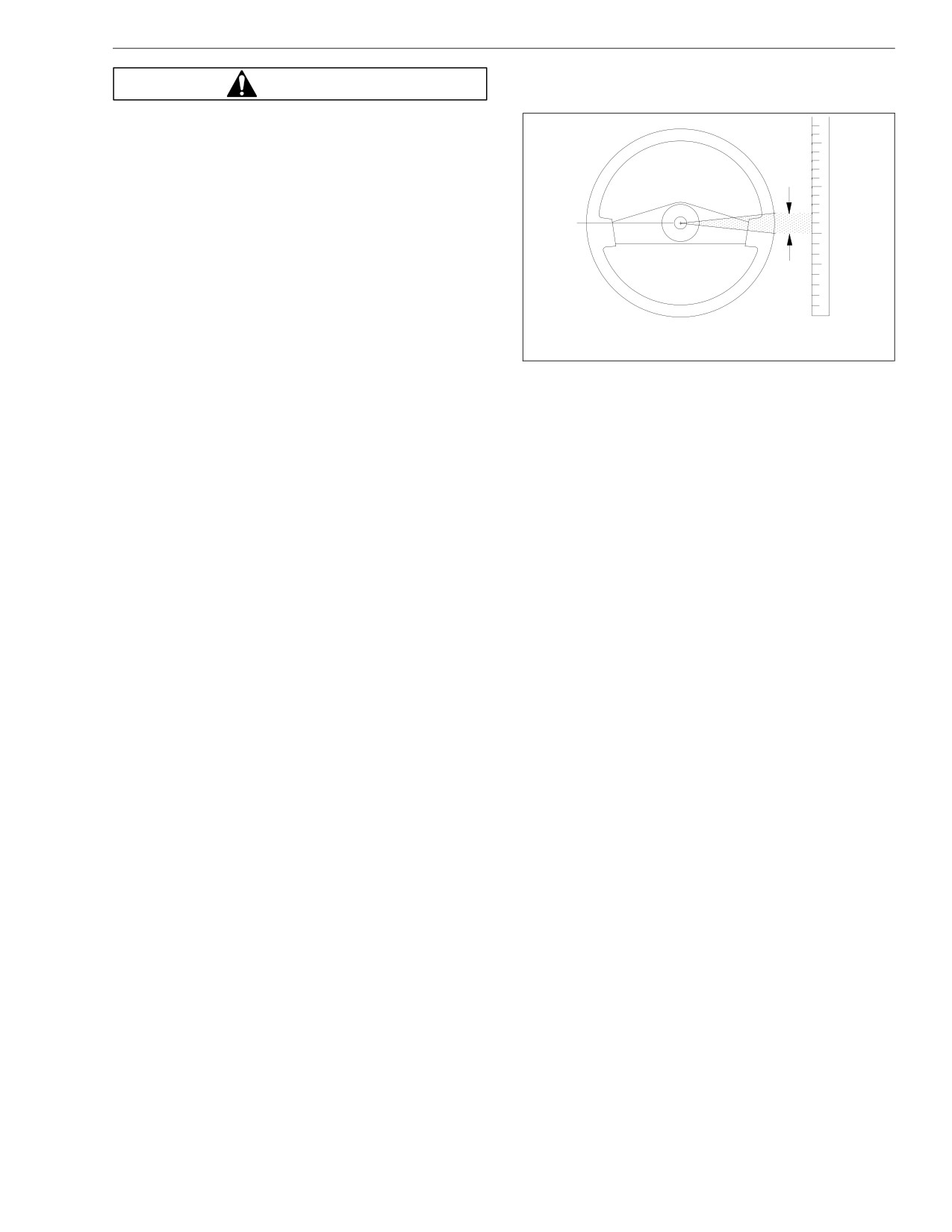
Pretrip Inspection and Daily Maintenance
justment of the linkage and steering gear before
WARNING
operating the vehicle.
Do not replace individual leaves of a damaged front
or rear suspension leaf spring assembly; replace
the complete spring assembly. Visible damage,
such as cracks or breaks, to one leaf causes hidden
A
damage to other leaves. Replacement of only the
visibly damaged part(s) is no assurance that the
spring is safe. If cracks or breaks exist on front
spring assemblies in either of the two top leaves, a
loss of vehicle control could occur. Failure to re-
place a damaged spring assembly could cause an
accident resulting in serious personal injury or
property damage.
21. Check the steering wheel for excessive play.
11/15/2000
f460158c
A. Lash Area
With the front tires pointing straight ahead, turn the
steering wheel until motion is observed at the front
Fig. 8.6, Measure Lash at the Steering Wheel
wheels. Align a reference mark on a ruler, then
slowly turn the steering wheel in the opposite direc-
22. Check the clutch pedal free-travel, if applicable.
tion until motion is again detected at the wheels.
Measure the lash (free play) at the rim of the steer-
The main indicator for assessing clutch wear is
ing wheel. See Fig. 8.6.
clutch pedal free-travel. Free-travel is a decreased
resistance felt at the top of the clutch pedal stroke.
Excessive lash exists if steering wheel movement
With the clutch pedal in this range, the clutch is
exceeds 4-3/4 inches (121 mm) with an 18-inch
fully engaged and the only resistance to clutch
(470-mm) steering wheel. If there is excessive lash,
pedal movement is return spring tension. Clutch
check the steering system for wear or incorrect ad-
pedal free-travel should be approximately 1-1/2 to 2
inches (38 to 51 mm). See Fig. 8.7. If the clutch
8.12
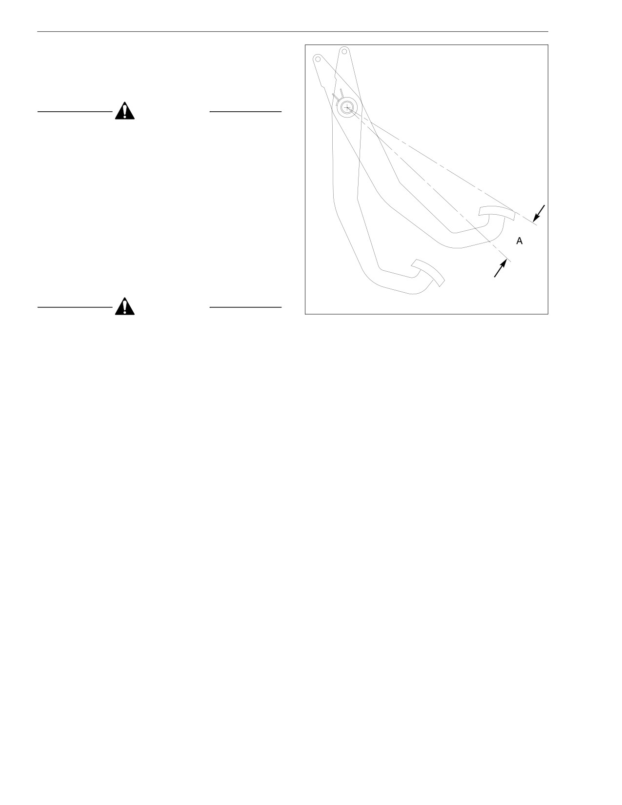
Pretrip Inspection and Daily Maintenance
pedal free-travel is less than 3/4 inch (19 mm), ad-
just the clutch internally.
For instructions, see Group 25 of the School Bus
Chassis Workshop Manual.
CAUTION
Excessive clutch free pedal may prevent complete
clutch disengagement; insufficient clutch pedal
free-travel causes slippage and short clutch life.
Never wait for the clutch to slip before making a
clutch adjustment.
23. Start the engine and make sure that the oil-
pressure warning system is working.
When the engine is started, the oil-pressure warn-
ing will come on until the oil pressure rises above a
preset minimum.
If the warning does not come on when the ignition
switch is turned to the ON position, repair the sys-
tem.
09/06/96
f250344
A. About 1-1/2 to 2 inches (38 to 51 mm)
CAUTION
Fig. 8.7, Check Clutch Pedal Free-Travel
Failure to repair the engine shutdown/ warning sys-
tem could result in a sudden engine shutdown with-
24. Make sure that the electric horn works.
out warning during vehicle operation.
25. Make sure that all of the lights are working.
8.13
Pretrip Inspection and Daily Maintenance
Turn on the headlights, dash lights, and emergency
handling and may lead to loss of vehicle control
flashers and leave them on.
resulting in property damage or personal injury.
If any of the gauge bulbs, the switch panel label
bulb, or the right- and left-turn indicator bulbs are
CAUTION
not working, replace them. If they still don’t work,
find and correct the problem. Turn off all of the
If the external breather tube or breather cap is miss-
lights. Shut down the engine.
ing or incorrectly installed, road dirt and debris can
adversely affect the operation of the brake chamber.
Once inside of the chamber, dirt and debris can
DANGER
cause the internal parts of the chamber to deterio-
rate faster.
Do not loosen or remove the parking brake clamp
ring for any purpose. See Fig. 8.8. The parking/
NOTE: Check vehicles operating under severe or
emergency brake section of the brake chamber is
adverse conditions more frequently.
not intended to be serviced. Serious injury or death
26. Inspect the air brake components (if so equipped)
may result from sudden release of the power
including the brake chamber pushrods, air reser-
spring.
voirs, and air lines.
Before doing any repairs or adjustments on a
Look for worn clevis pins on brake chamber push-
service/parking brake chamber, read the applicable
rods and missing or damaged cotter keys on the
warnings and instructions in Group 42 of the School
brake chamber pushrod clevis pins. Replace worn
Bus Chassis Workshop Manual.
clevis pins and install new cotter keys if necessary.
WARNING
Visually inspect the piston rod engagement with the
clevis. At least seven threads of engagement are
required; there should be 1 inch (25 mm) of clear-
Do not operate the vehicle with the front brakes
ance from the center line of the clevis pin hole to
backed off or disconnected. Backing off or discon-
the end of the piston rod. See Fig. 8.9. See Group
necting the front brakes will not improve vehicle
42 of the School Bus Chassis Workshop Manual for
adjustment procedures.
8.14
Pretrip Inspection and Daily Maintenance
See if the chamber piston rod is in line with the
with new ones. Do not repair damaged reservoirs.
slack adjuster. Misalignment can cause the piston
Old or used reservoirs are not acceptable as re-
rod to rub on the nonpressure chamber and cause
placements. If a reservoir requires replacement,
a dragging brake. See Group 42 of the School Bus
see Group 42 of the School Bus Chassis Work-
Chassis Workshop Manual if the chamber piston
shop Manual for instructions.
rod is improperly aligned.
Inspect the air lines as follows:
Visually inspect the exterior surfaces of the cham-
26.1
Check the clearance between the hoses,
ber for damage. Make sure that breather holes in
exhaust manifold, and turbocharger, or other
the nonpressure section(s) are open and free of
hot spots. Excessive heat will cause the ma-
debris. See Group 42 of the School Bus Chassis
terial in the hoses to deteriorate rapidly or
Workshop Manual for instructions to replace dam-
become brittle. Provide at least six inches
aged parts.
(150 mm) of clearance. More clearance is
On all parking brake installations, check for the
recommended if the hose is located above
presence of an end cover cap or dust plug and
the heat source.
make sure that the cap or plug is securely snapped
26.2
Check for kinks, dents, or swelling of the
into place. On most MGM parking brake chambers
hoses. If a hose is damaged, replace it with
equipped with an integral release bolt, an end cover
one of the same size and type.
cap is installed over the release bolt. Be sure that
the end cover cap is snapped tightly into place.
26.3
Do not route the hose on top of anything
likely to be stepped on or walked on.
Check for rusted connections, missing snap rings,
26.4
Check for damage to hoses located near
and damaged camshaft grease seals. Repair or
moving parts, such as drivelines, suspen-
replace damaged or missing parts.
sions, and axles. If the moving parts are
Check the air reservoir band fasteners. Make sure
catching or pinching the lines, make correc-
that the outside surfaces of the reservoirs are
tions as needed.
painted to prevent corrosion damage. Inspect the
reservoir surfaces for damage, such as cracks and
dents. Replace corroded or damaged reservoirs
8.15
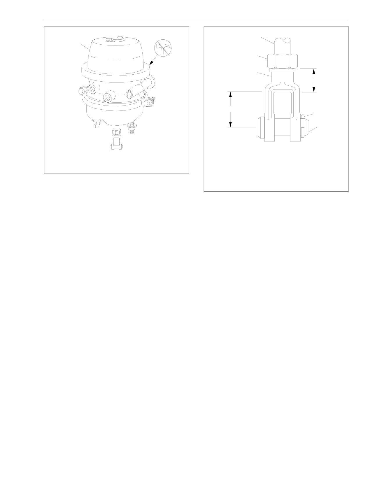
Pretrip Inspection and Daily Maintenance
1
1
2
A
3
B
A
4
5
08/20/93
f420225a
02/22/2000
f421352
A. Minimum of 1 inch (25 mm) of clearance between
A. Do not remove this clamp ring.
center line of clevis pin hole and piston rod end.
B. Minimum of 7 threads engagement.
1. Brake Chamber
1. Piston Rod
4. Cotter Key
Fig. 8.8, Brake Chamber and Clamp Ring
2. Piston Rod Nut
5. Clevis Pin
(MGM TR series)
3. Clevis
Fig. 8.9, Piston Rod Engagement with the Clevis
8.16
Pretrip Inspection and Daily Maintenance
26.5
Check for hose damage caused by abrasion.
26.8
Inspect air tubing, especially tubing made of
If a hose is abraded, replace it. Check for
nylon. In cold weather, nylon tubing is sensi-
the cause of the abrasion, such as loose or
tive to damage, such as nicks or cuts. Re-
damaged hose clamps. Repair or replace
place nicked or cut tubing, even if it is not
the clamps as needed.
leaking.
26.6
Observe the hose cover condition, especially
26.9
Check the bend radii of all hoses. See
hoses exposed to water splash and ice. If
Fig. 8.10. The minimum bend radius of a
any hose is dried out or ragged (the wire or
hose is that bend which the hose will with-
liner is showing through the cover), replace
stand without experiencing damaging
the hose.
stresses or kinking. For minimum bend ra-
dius values, see Group 42 of the School
26.7
Inspect the front air brake lines for leaks at
Bus Chassis Workshop Manual.
the fitting where they enter the air chamber.
When a rubber hose bend does not meet
With an assistant at the front wheels to in-
minimum radius requirements, the outside
spect the brake lines, turn the wheels to full
may appear smooth even if the inner tube is
lock in one direction. While holding the ser-
kinked. Reroute the hose or replace it with
vice brake pedal down, inspect the front
one of adequate length if the bend radius is
brake air lines closely where they enter the
not within minimum specifications.
air chambers.
26.10
Check straight hose installations (those
Turn the wheels to full lock in the other di-
hoses that do not bend along their routings).
rection, hold the service brake pedal down,
Pressure changes can cause a hose to
and repeat the inspection.
lengthen up to two percent, or shorten up to
four percent. A 100-inch (2540-mm) length of
If there is a leak, the hose should be re-
hose, for example, can contract to 96 inches
placed.See Group 42 of the School Bus
(2440 mm). If the hose has no slack when it
Chassis Workshop Manual for the hose re-
is exhausted of air, replace it with one of
placement procedure.
adequate length to avoid a possible blow-off
from the fitting during vehicle operation.
8.17
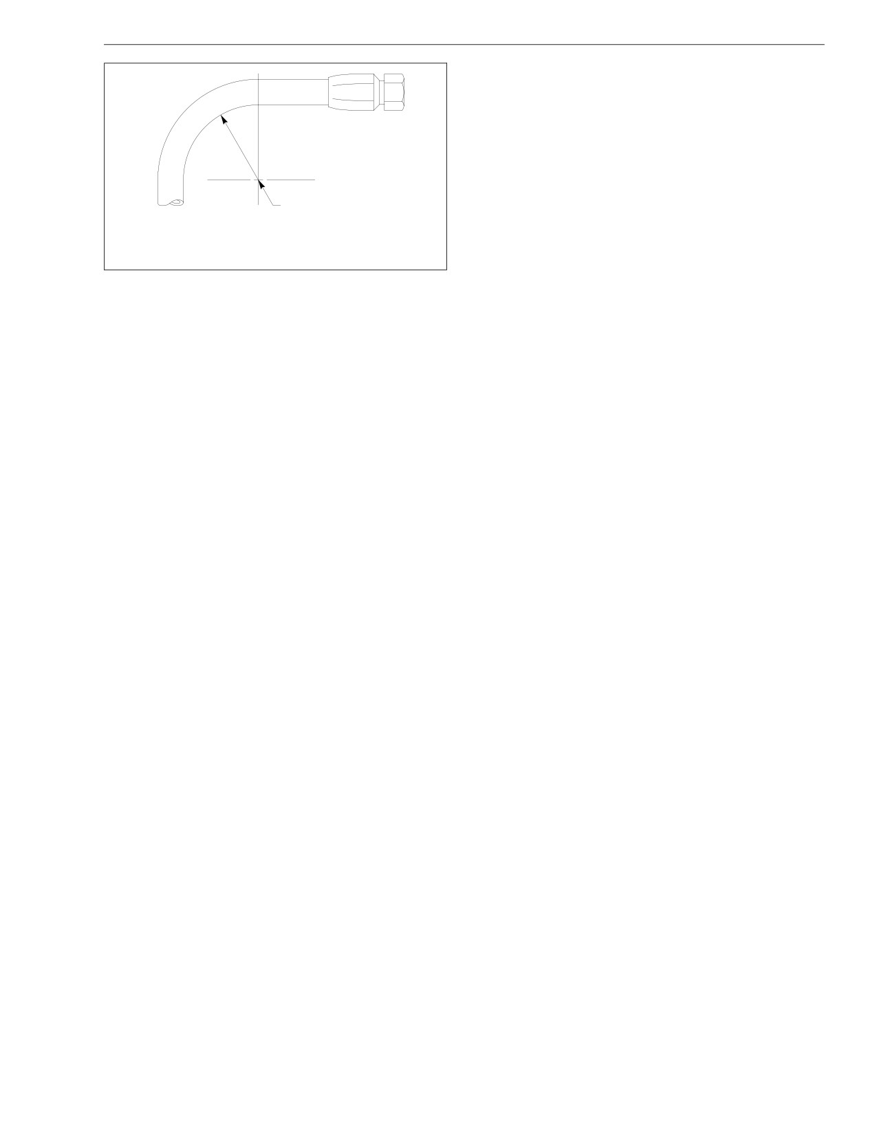
Pretrip Inspection and Daily Maintenance
27.2
If the axle assembly is not equipped with a
dust shield or backing plate, measure the
axle brake lining thickness. If any of the
brake linings are worn to less than 1/4 inch
(6.5 mm) at the thinnest point, replace the
linings on all brake assemblies on that axle.
See Group 42 of the School Bus Chassis
Workshop Manual for lining replacement in-
structions and camshaft endplay inspection.
11/03/94
A
f420329a
27.3
If the axle assembly is equipped with a dust
NOTE: The center of the hose bend radius should be
shield or backing plate, remove the inspec-
well away from the fitting.
tion plugs to inspect the brake lining thick-
A. Bend Radius
ness. If any of the brake linings are worn to
less than approximately 1/4 inch at the thin-
Fig. 8.10, Bend Radius
nest point, replace the linings on all brake
assemblies on that axle. See Group 42 of
26.11
Check for kinked or twisted hoses. A seven-
the School Bus Chassis Workshop Manual
percent twist in the hose can reduce its life
for lining replacement instructions and cam-
by up to 90 percent. Also, a twisted hose
shaft endplay inspection.
under pressure tends to untwist. This could
cause it to loosen the fitting. Reconnect
27.4
Install the inspection plugs in the dust
hoses that are twisted.
shields or backing plates, if so equipped.
27. Check the brake lining wear on vehicles equipped
27.5
Remove the chocks from the tires.
with air brakes. Proper brake operation is depen-
28.
Make sure that the brakes are adjusted on all ax-
dant on periodic maintenance and inspection of the
les.
brake linings.
Adjust the brakes if necessary. See Group 42 of
27.1
Set the parking brake, and chock the tires to
the School Bus Chassis Maintenance Manual for
prevent vehicle movement.
checking and adjusting procedures.
8.18
Pretrip Inspection and Daily Maintenance
IMPORTANT: Brake checking and adjusting is nec-
See the tire manufacturer’s recommenda-
essary for all vehicles, including those equipped
tions for the correct tire inflation pressures
for the vehicle load.
with automatic slack adjusters.
29. Check the tire inflation pressures and inspect each
Overinflation gives the treaded surface of
tire for bulges, cracks, cuts, and punctures.
the tire a convex shape. See Fig. 8.12. This
causes extreme tire wear in the middle part
IMPORTANT: The load and cold inflation pres-
of the tire since this section is primarily in
sure must not exceed the rim or wheel manu-
contact with the road.
facturer’s recommendations, even though the
Underinflation gives the tread surface a con-
tire may be approved for a higher load or infla-
cave shape. See Fig. 8.12. This causes ex-
tion. Some rims and wheels are stamped with
cessive tire wear on the outer edges of the
a maximum load and maximum cold inflation
tire since they are primarily in contact with
rating. See Group 40 of the School Bus Chas-
the road.
sis Workshop Manual for the correct tire infla-
tion pressure for the vehicle load or consult
WARNING
the rim or wheel manufacturer if they are not
stamped. If the load exceeds the maximum rim
Do not operate the vehicle with underinflated or
or wheel capacity, the load must be adjusted
overinflated tires. Incorrect inflation can stress the
or reduced.
tires and make the tires and rims more susceptible
to damage, possibly leading to rim or tire failure
29.1
Check the inflation pressures of the tires be-
and loss of vehicle control, resulting in serious per-
fore each trip using an accurate tire pres-
sonal injury or death.
sure gauge. See Fig. 8.11. Check the tires
when cool. Be sure that valve stem caps are
29.2
If a tire has been run flat or underinflated,
on every tire and that they are screwed on
check the wheel for proper lockring and side
finger-tight. Inflate the tires to the correct
ring seating, and possible wheel, rim, or tire
pressures if needed.
damage before adding air.
8.19
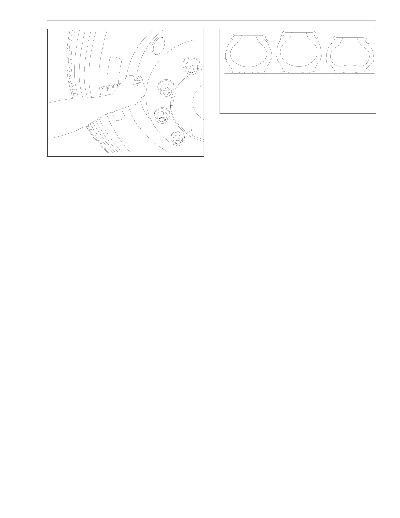
Pretrip Inspection and Daily Maintenance
A
B
C
11/03/94
f400062a
A. Tire correctly inflated.
B. Tire overinflated.
C. Tire underinflated.
Fig. 8.12, Check for Proper Tire Inflation
pressure loss of 4 psi (28 kPa) or more in a
tire may indicate damage. Inspect and repair
or replace the tire.
11/03/94
f400061
29.5
If the tires are wearing irregularly, rotate
Fig. 8.11, Check Tire Inflation Pressures
them. If the front steering axle tires become
irregularly worn, move them to the drive
29.3
Moisture inside a tire can result in body ply
axle. See Fig. 8.13. Have the front axle
separation or a sidewall rupture. During tire
alignment checked to determine the cause
inflation, compressed air reservoirs and lines
of irregular tire wear. In a dual assembly, if
must be kept dry. Use well-maintained inline
one tire wears faster than its mate, reverse
moisture traps and service them regularly.
the position of the two tires. See Fig. 8.14.
29.4
Inspect the tires for bulges, cracks, cuts, or
Government regulations require the removal
penetrations. A tire pressure check will assist
of front axle tires at 4/32-inch (3-mm) re-
in uncovering hidden damage. A weekly
maining tread depth and rear axle tires at
8.20
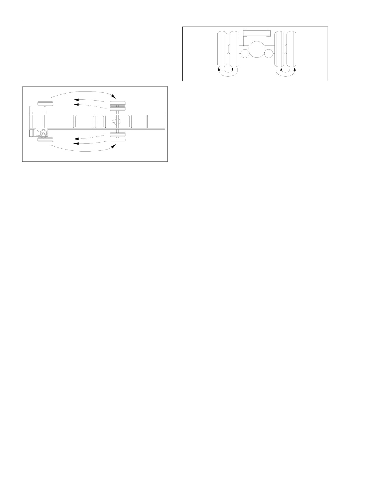
Pretrip Inspection and Daily Maintenance
2/32-inch (1.5-mm) remaining tread depth.
However, front axle tires may be rotated to
the drive axles to use the remaining 2/32-
inch (1.5-mm) tread rubber.
See Group 40 of the School Bus Chassis
Workshop Manual for additional information
on tire matching, spacing of dual tires, and
07/25/96
f400116
causes of abnormal tire wear.
Fig. 8.14, Dual Assembly Rotation
Check the wheel nuts or rim nuts for indications of
looseness. Remove all dirt and foreign material
from the assembly. Dirt or rust streaks from the
stud holes, metal buildup around stud holes, or out-
of-round or worn stud holes, may be caused by
loose wheel nuts. See the School Bus Chassis
Maintenance Manual for torque specifications and
the correct tightening sequences.
Examine the wheel assembly components (includ-
07/25/96
f400115
ing rims, rings, flanges, studs, and nuts) for cracks
or other damage.
Fig. 8.13, Front Axle to Rear Axle Rotation
See Group 33 and Group 35 of the School Bus
29.6
Also inspect tires for oil contamination. Fuel
Chassis Workshop Manual for service procedures
oil, gasoline, and other petroleum deriva-
for the studs and hubs, and Group 40 of the
tives, if allowed to contact the tires, will
School Bus Chassis Workshop Manual for wheel
soften the rubber and destroy the tire.
and tire servicing. Replace broken, cracked, badly
30. Check for indications of loose wheel nuts or rim
worn, bent, rusty, or sprung rings and rims. Be sure
nuts and examine each wheel component.
8.21
Pretrip Inspection and Daily Maintenance
that the rim base, lockring, and side ring are
should cut out the air compressor at approxi-
matched according to size and type.
mately 125 psi (862 kPa). With the engine
idling, make a series of foot valve applica-
tions. The air governor should cut in the air
WARNING
compressor at approximately 95 psi (655
kPa). If the air governor does not cut in and
Have any worn or damaged wheel components re-
out as described above, adjust it to these
placed by a qualified person using the wheel manu-
specifications. If the air governor cannot be
facturer’s instructions and the wheel industry’s
adjusted or repaired, replace it before oper-
standard safety precautions and equipment. Other-
ating the vehicle.
wise a vehicle or workshop accident could occur,
possibly resulting in serious personal injury or
31.2
Check the air pressure buildup time as fol-
death.
lows:
Release the parking brake by pushing in the
CAUTION
parking brake control valve knob.
With the air system fully charged to 125 psi
Insufficient wheel nut (rim nut) torque can cause
(862 kPa), make one full brake application
wheel shimmy, resulting in wheel damage, stud
and note the air pressure reading on the
breakage, and extreme tire tread wear. Excessive
gauge. Continue to reduce the air pressure
wheel nut torque can break studs, damage threads,
by moderate brake applications to a maxi-
and crack discs in the stud hole area. Use the rec-
mum of 90 psi (620 kPa), then run the en-
ommended torque values and follow the proper
gine at governed rpm. If the time required to
tightening sequence.
raise the air pressure to 125 psi (862 kPa) is
31. Check air brake system components for correct op-
more than 30 seconds, eliminate any leaks
eration as follows:
or replace the air compressor before operat-
31.1
Release the parking brake by pushing in the
ing the vehicle.
parking brake control valve knob. Check the
31.3
Check the air pressure reserve. With the air
air governor cut-in and cut-out pressures.
system fully charged to 125 psi (862 kPa),
Run the engine at fast idle. The air governor
stop the engine and note the air pressure.
8.22
Pretrip Inspection and Daily Maintenance
Then make one full brake application and
one minute and note the air pressure gauge
observe the pressure drop. If it drops more
reading. Observe the air pressure drop in psi
than 25 psi (172 kPa), all areas of leakage
(kPa) per minute.
must be eliminated before operating the ve-
If leakage exceeds the limits shown in
hicle.
Table 8.1, repair all areas of leakage before
driving the vehicle.
WARNING
Maximum Allowable Service Brake Air Leakage in psi
Before operating the vehicle, be sure that the park-
(kPa) Per Minute
ing brake passes the following tests. Otherwise an
Released
Applied
unexpected parking brake application could occur,
2
(14)
3
(21)
causing some loss of vehicle control and possibly
resulting in serious personal injury.
Table 8.1, Maximum Allowable Service Brake Air
Leakage
31.4
Check the air leakage in the system.
32. Test the service brakes before leaving the lot.
With the parking brake applied, the transmis-
sion out of gear, and the tires chocked,
Depress the brake pedal, release the parking
charge the air system until a cutoff pressure
brake, and check that the brake system warning
of 125 psi (862 kPa) is reached.
light goes out. If the warning light remains on after
releasing the parking brake, correct the problem
With the service brakes released, shut down
before driving off.
the engine, wait one minute and note the air
pressure gauge reading. Observe the air
If equipped with air brakes, test the brakes (when
pressure drop in psi (kPa) per minute.
starting to move the vehicle and before picking up
speed) with the foot valve and parking brake valve
Charge the air system until a cutoff pressure
to be sure that they will bring the vehicle to a safe
of 125 psi (862 kPa) is reached. With the
stop.
parking brake released and the service
brake applied, shut down the engine, wait
33. Test the parking brakes on a 20-percent grade.
8.23
Pretrip Inspection and Daily Maintenance
Apply the hand brake or pull the parking brake con-
trol valve knob with the vehicle on a 20-percent
grade (the ramp surface should be made of Port-
land cement or the equivalent). If the parking brake
does not hold the vehicle, repair the parking brake
system.
8.24
9
In an Emergency
Hazard Warning Lights
9.1
Towing
9.1
Emergency Starting With Jumper Cables
9.3
Running Out of Fuel
9.5
Changing a Flat Tire
9.5
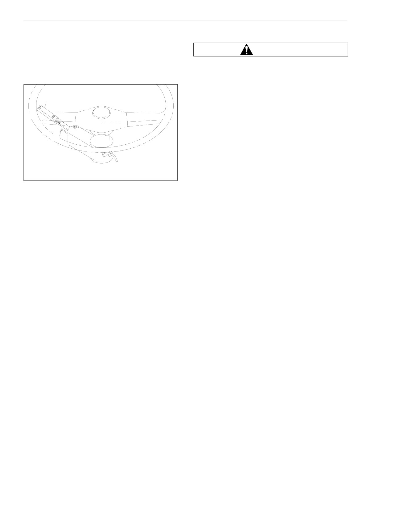
In an Emergency
Hazard Warning Lights
Towing
The hazard warning light tab is located on the turn sig-
nal lever. See Fig. 9.1. To operate the hazard lights,
WARNING
pull the tab out. All of the turn signal lights and both of
the indicator lights on the control panel will flash.
Do not tow an unbraked vehicle if the combined
weight of both vehicles is more than the sum of the
Push the tab in to cancel the hazard warning lights.
gross axle weight ratings (GAWR) of the towing ve-
hicle. Otherwise brake capacity will be inadequate,
which could result in personal injury or death.
1
IMPORTANT: When it is necessary to tow the ve-
hicle, follow the instructions below closely to pre-
vent damage to the vehicle.
When towing or pushing any vehicle equipped with
2
an Allison transmission, disconnect the driveshaft
at the rear axle and support it as necessary, re-
gardless of the distance or speed traveled.
07/09/96
f461080
Front Towing Hookup
1. Turn Signal Lever
2. Hazard Warning Light Tab
1. Disconnect the battery ground cable.
Fig. 9.1, Hazard Warning Light Tab
2. If the vehicle is to be lifted and towed, remove the
driveaxle shafts.
9.1
In an Emergency
6. Connect the clearance lights, taillights, and signal
CAUTION
lights. Connect any special towing lights required by
local regulations.
Failure to remove the axle shafts when towing the
vehicle with the rear wheels on the ground could
WARNING
result in damage to the transmission and other
parts.
Before releasing the parking brakes, make the con-
3. Cover the ends of the hubs with metal plates or
nection to the towing vehicle or chock the tires on
plywood cut to fit the axle opening and drilled to fit
the disabled vehicle. Failure to do so could result in
the axle shaft studs. This prevents lubricant from
hazardous conditions because the vehicle could
leaking out, and will keep contaminants from getting
suddenly roll and injury could occur.
into the axle lubricant and damaging the wheel
bearings.
CAUTION
WARNING
Before attempting to tow a vehicle with an air sus-
pension (and during the towing operation), ensure
Due to the many variables that exist in towing, posi-
that the air suspension is properly charged. Charge
tioning the lifting and towing device is the sole re-
the suspension through the Schrader valve on the
sponsibility of the tow vehicle operator. The opera-
air dryer. Attempting to tow a vehicle with an im-
tor must be familiar with standard towing industry
properly charged air suspension may result in dam-
safety measures. Improper procedures could result
age to the chassis and body.
in personal injury or death.
7. Release the parking brake.
4. Attach the towing device.
5. Lift the vehicle, and secure the safety towing
Rear Towing Hookup
chains. If additional clearance is needed, remove
1. Position the front tires so that they point straight
the front wheels.
ahead and secure the steering wheel in this posi-
tion.
9.2
In an Emergency
2. Disconnect the battery ground cable.
Emergency Starting With
Jumper Cables
WARNING
When using jumper cables, follow the instructions
Due to the many variables that exist in towing, posi-
below.
tioning the lifting and towing device is the sole re-
sponsibility of the tow vehicle operator. The opera-
WARNING
tor must be familiar with standard towing industry
safety measures. Improper procedures could result
Batteries release explosive gas. Do not smoke when
in personal injury or death.
working around batteries. Put out all flames and re-
3. Attach the towing device.
move all sources of sparks or intense heat in the
4. Lift the vehicle, and secure the safety towing
vicinity of the battery. Do not allow the vehicles to
touch each other. Do not lean over the batteries
chains.
when making connections, and keep all other per-
5. Connect the clearance lights, taillights, and signal
sons away from the batteries. Failure to follow
lights. Also connect any special towing lights re-
these precautions could lead to severe personal in-
quired by local regulations.
jury as a result of an explosion or acid burns.
CAUTION
CAUTION
Before attempting to tow a vehicle with an air sus-
Make sure both starting systems have the same
pension (and during the towing operation), ensure
voltage outputs, and avoid making sparks. Other-
that the air suspension is properly charged. Charge
wise the vehicle charging systems could be se-
the suspension through the Schrader valve on the
verely damaged. Also, do not attempt to charge iso-
air dryer. Attempting to tow a vehicle with an im-
lated, deep-cycle batteries with jumper cables.
properly charged air suspension may result in dam-
Follow the manufacturer’s instructions when charg-
age to the chassis and body.
ing deep-cycle batteries.
9.3
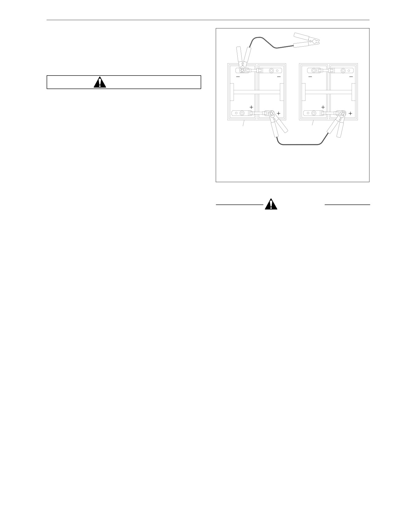
In an Emergency
1. Set the parking brake and turn off the lights and all
other electrical loads.
2. Connect one end of a jumper cable to the positive
D
terminal of the booster battery, and connect the
C
other end of the cable to the positive terminal of the
discharged battery. See Fig. 9.2.
WARNING
Do the next step exactly as instructed and do not
allow the clamps of one cable to touch the clamps
of the other cable. Otherwise, a spark could occur
near a battery, possibly resulting in severe personal
injury from explosion and acid burns.
1
A
2
B
3. Connect one end of the second jumper cable to the
negative terminal of the booster battery, and con-
nect the other end of the cable to a ground at least
12 inches (300 mm) away from the batteries of the
08/21/96
f541286
vehicle needing the start. The vehicle frame is usu-
A.
1st
C.
3rd
ally a good ground. Do not connect the cable to or
B.
2nd
D. To Frame (ground)
near the discharged batteries.
1.
Booster Battery
2. Discharged Battery
4. Start the engine of the vehicle with the booster bat-
Fig. 9.2, Jumper Connections
teries, and let the engine run for a few minutes to
charge the batteries of the other vehicle.
CAUTION
Don’t crank the engine for more than 30 seconds at
a time during any of the following procedures. Wait
9.4
In an Emergency
two minutes after each try to allow the starter to
fuel tanks. Combustion of diesel fuel oil or fuel va-
cool. Failure to do so could cause starter damage.
pors could result, possibly causing personal injury
or property damage.
5. Attempt to start the engine of the vehicle with the
batteries receiving the charge.
1. If possible, stop the vehicle on a level surface,
away from traffic.
6. When the engine starts, let it idle for a few minutes.
2. Set the parking brake.
WARNING
3. See the engine manufacturer’s manual for instruc-
tions.
Do the next step exactly as instructed and do not
4. Call the Freightliner Customer Assistance Center at
allow the clamps of one cable to touch the clamps
1-800-385-4357 or 1-800-FTL-HELP.
of the other cable. Otherwise, a spark could occur
near a battery, possibly resulting in severe personal
injury from explosion and acid burns.
CAUTION
7. Disconnect the grounded cable from the frame or
Don’t crank the engine for more than 30 seconds at
other non-battery location; then disconnect the
a time during any of the following procedures. Wait
other end of the cable.
two minutes after each try to allow the starter to
8. Disconnect the remaining cable from the newly
cool. Failure to do so could cause starter damage.
charged battery first; then disconnect the other end.
5. Start the engine.
Running Out of Fuel
Changing a Flat Tire
IMPORTANT: If a flat tire occurs while driving,
WARNING
gradually decrease vehicle speed. Holding the
steering wheel firmly, move to a safe place on the
Do not mix gasoline or alcohol with diesel fuel. This
side of the road.
mixture could cause an explosion. When filling fuel
tanks, do not smoke or use an open flame near the
9.5
In an Emergency
1. If possible, stop the vehicle on a level surface,
8.
Install the spare wheel and lug nuts. Make sure that
away from traffic.
the beveled sides of the nuts face inward, or, on
hub-piloted wheels, make sure that the hub-pilot
2. Apply the parking brake and place the transmission
pad is centered at the top.
in Park (P) or Neutral (N), for automatic transmis-
sions, or in First (1) gear for manual transmissions.
9.
In a star pattern, tighten the nuts evenly until snug.
Turn the ignition switch to the OFF position.
10.
See Group 40 of the School Bus Chassis Work-
3. Turn on the emergency flashers.
shop Manual for wheel tightening patterns and
torque specifications. Lower the vehicle until the
4. Block the wheel diagonally opposite the wheel be-
wheel touches the ground. Tighten the nuts.
ing changed.
11.
Finish lowering the vehicle to the ground, then re-
5. Remove the spare wheel, jack, jack handle, and lug
move the jack.
wrench from storage.
12.
Remove the block, then stow the jack, jack handle,
NOTE: The jacking point for the front and rear
and lug wrench.
wheels is directly under the axle.
13.
After operating the vehicle for 50 to 100 miles (80
6. Place the jack on a solid surface. Insert the jack
to 160 km), retighten the wheel nuts to the speci-
handle and pump the handle slightly. Do not raise
fied torque values.
the wheel off of the ground yet. Loosen the wheel
lug nuts, but do not remove them.
IMPORTANT: The dual rear wheels are attached
using two-element lug nuts. The larger nut retains
the outer dual. The inner square stud retains the
inner dual. Remove and install these nuts sepa-
rately. The rear dual outer lug nut must be loos-
ened to check and retighten the inner nut.
7. Raise the vehicle until the wheel is off of the
ground. Remove the lug nuts and the wheel.
9.6
10
Specifications
Replacement Light Bulbs
10.1
Fluids and Lubricants
10.1
Fuse/Relay/Circuit Breaker Identification
10.2
Specifications
Replacement Light Bulbs
Fluid and Lubricant Specifications
Recommended Fluid or
See Table 10.1 for a listing of replacement light bulbs.
Component
Lubricant
Front Axle Spindle Pins, Tie
Replacement Light Bulbs
Multipurpose Grease
Rods, Drag Link,
Lithium 12 Hydroxy
Light Location
Part Number
Intermediate Steering Shaft,
Stearate NLGI No. 2; for
Headlight, Rectangular, Halogen
WEE H6054
Front Brake and Clutch
temperatures below 0°F
Headlight, Rectangular, Standard
WEE 6052
Cable Pedal Shafts, Slip
(-18°C), use MIL-G-10924B
Spline and Universal Joints
Front Turn Signal Light
WEE 1156
Hydraulic Brake Master
Heavy-Duty DOT 3 Brake
Front Side Marker Light
WEE 193
Cylinder
Fluid
Instrument Panel Light
WEE 161
Brake and Clutch Pedal
Starplex 2 (lithium soap-
Rocker Switch Light
SPR 904 404
Pivots
based grease)
Table 10.1, Replacement Light Bulbs
Engine Oil
SAE 15W-40 HD
Transmission:
Fluids and Lubricants
SAE 40 or 50 above +10°F
Eaton/Fuller
(-12°C); SAE 30 below
See Table 10.2 for a listing of fluid and lubricant specifi-
+10°F (-12°C)
cations.
Allison *
Dexron III ATF
IMPORTANT: For vehicles with extended warran-
Grade No. 2-0 or 2-D
Fuel
Diesel Fuel
ties (and equipped with automatic transmissions),
use only TranSynd synthetic ATF.
Brake Caliper V-Ways and
Aeroshell Grade 5 (ES-
Anchor Plate Rails
1246)
Hypoid Gear Oil API
Rear Axle Differential
Service Classification GL-5
10.1
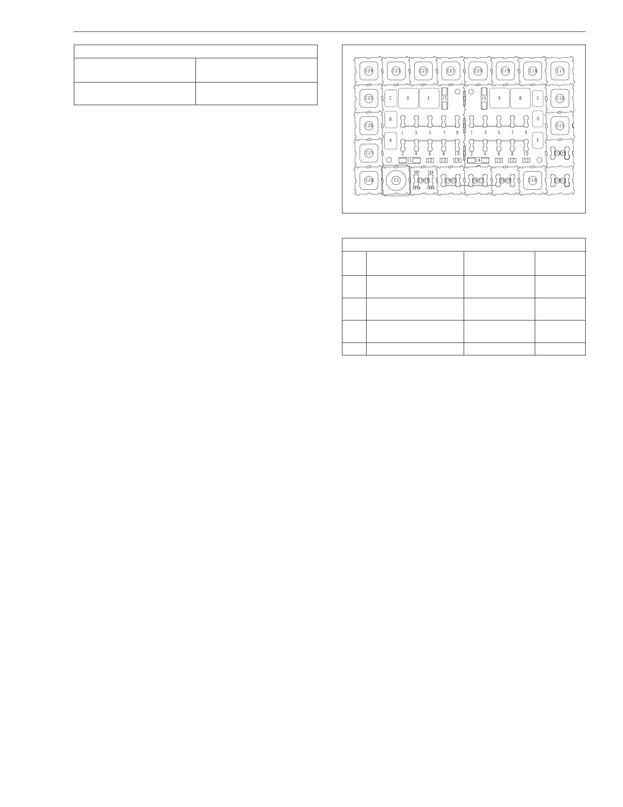
Specifications
Fluid and Lubricant Specifications
Recommended Fluid or
Component
Lubricant
50% Water/50% Ethylene
Engine Coolant
Glycol Antifreeze†
A B
* For vehicles with extended warranties, use only TranSynd synthetic ATF.
†
See Group 20 of the School Bus Chassis Maintenance Manual for
Freightliner specifications.
Table 10.2, Fluid and Lubricant Specifications
Fuse/Relay/Circuit Breaker
Identification
NOTE: The fuse/relay/circuit breaker panel is lo-
06/13/96
f541287
cated on the right side of the dash. Depending on
Fig. 10.1, Fuse/Relay/Circuit Breaker Panel
vehicle options, fuse/relay/circuit breaker locations
may vary. See Fig. 10.1 or Table 10.3 for fuse/
Fuse/Relay/Circuit Breaker Identification
relay/circuit breaker locations and identification.
Pos.
Description
Part Number
Rating
No.
Ignition Bus/Standard
AA
680 545 00 05
—
Circuits
Parking Brake Relay/
AB
680 545 00 05
—
DRL
Ignition Bus/Optional
AC
680 545 00 05
—
Circuits
AD Brake Light Relay
23-11276-011
—
10.2
Specifications
Fuse/Relay/Circuit Breaker Identification
Fuse/Relay/Circuit Breaker Identification
Pos.
Pos.
Description
Part Number
Rating
Description
Part Number
Rating
No.
No.
231284 000010
10A Fuse
231284 000015
15A Fuse
Fuel Solenoid/Backup
A2
B2
Panel Lights
Lights
680 545 19 66
10A C.B.
680 545 20 66
15A C.B.
231284 000010
10A Fuse
LF 257 020
20A Fuse
A4
Fan Clutch Relay
B3
Fog Lights
680 545 19 66
10A C.B.
680 545 21 66
20A C.B.
231284 000010
10A Fuse
231284 000015
15A Fuse
Instrument Panel
A6
B4
Stoplight Switch
Feed
680 545 19 66
10A C.B.
680 545 16 66
15A C.B.
A8
Hydraulic Brakes
231284 000005
5A Fuse
LF 257 020
20A Fuse
Daytime Running
B5
231284 000010
10A Fuse
Lights, Battery Feed
680 545 17 66
20A C.B.
A10
Relay Coil Feeds
680 545 19 66
10A C.B.
231284 000015
15A Fuse
B6
Horn
Ignition Controlled
680 545 01 34
20A Fuse
680 545 20 66
15A C.B.
A15
Relay, to Optional
680 545 12 66
20A C.B.
LF 257 020
20A Fuse
Ignition Bus
B7
Turn Signal Flasher
BA
Fog Light Relay
23-11276-011
—
680 545 21 66
20A C.B.
Taillight/Marker Lights
231284 000015
15A Fuse
BB
23-11276-011
—
Ignition Switch,
Relay
B8
Battery Feed
680 545 20 66
15A C.B.
BC
Panel Light Relay
680 545 00 05
—
231284 000015
15A Fuse
BD
Headlight Relay, Right
680 545 00 05
—
B9
Headlight, Right
BE
Headlight Relay, Left
680 545 00 05
—
680 545 16 66
15A C.B.
231284 000015
15A Fuse
231284 000015
15A Fuse
B1
Taillights
B10
Headlight, Left
680 545 20 66
15A C.B.
680 545 16 66
15A C.B.
10.3

Specifications
Fuse/Relay/Circuit Breaker Identification
Fuse/Relay/Circuit Breaker Identification
Pos.
Pos.
Description
Part Number
Rating
Description
Part Number
Rating
No.
No.
Ignition Controlled
680 545 01 34
20A Fuse
C17 ABS Relay
23-11276-011
—
B14
Relay, to Standard
C18 ABS Relay
23-11276-011
—
Ignition Bus
680 545 12 66
20A C.B.
C19 ABS Relay
23-11276-011
—
Hazard Warning
C20 ABS Relay
23-11276-011
—
Flasher:
C1
Thermal
681 822 00 21
—
Table 10.3, Fuse/Relay/Circuit Breaker Identification
Solid State
680 822 00 21
—
231284 000010
10A Fuse
C2
Accessory Feed
680 545 19 66
10A C.B.
231284 000010
10A Fuse
C3
Ether Start
680 545 19 66
10A C.B.
LF 257 020
20A Fuse
Fuel/Water Separator,
C4
Battery Power
680 545 21 66
20A C.B.
231284 000005
5A Fuse
Diagnostic Connector,
C5
Battery Power
680 545 19 66
10A C.B.
231284 000005
Hydraulic ABS,
C6
—
Battery Power
680 545 19 66
Fuel/Water Separator
C10
23-11276-011
—
Relay
Automatic
C15
Transmission
PAC14100455
—
Modulator
10.4
Index
Subject
Page
Subject
Page
Subject
Page
A
Starting the Vehicle in the
Turn Signal Lever
2.5
Correct Gear
4.1
Air Brake System
7.4
Vehicle Overload, or
D
Automatic Slack Adjusters
7.8
Overloading the Clutch
4.1
General Information
7.4
Cold Weather Operation
3.13
Driveline Parking Brake Burnishing . .
7.1
Meritor WABCO® Antilock
Caterpillar
3.14
Braking System (ABS), Air
Cummins
3.15
E
Brake Systems
7.6
General Information
3.13
Operation
7.5
Emergency Starting With Jumper
Mercedes-Benz
3.15
Cables
9.3
Allison Automatic Transmissions
5.2
Cold Weather Starting
3.5
Engine Braking System (optional) . .
3.19
General Information
5.2
Caterpillar
3.5
Constant-Throttle Valves
Operation
5.3
Cummins
3.6
(MBE900 only)
3.19
Mercedes-Benz
3.6
Engine Break-In
3.7
C
Controls
2.1
Caterpillar
3.7
Changing a Flat Tire
9.5
Allison Automatic Transmission
Cummins
3.7
Clutch Adjustments
4.2
Controls
2.6
Mercedes-Benz
3.7
Clutch Lubrication
4.3
Cruise Control
2.7
Engine Operation
3.8
Clutch Operation
4.1
Electric Horn
2.8
Caterpillar
3.8
Coasting With the Clutch
Hazard Warning Light Tab
2.5
Cruise Control
3.12
Released (pedal depressed)
Headlight Dimmer Switch
2.5
Cummins
3.10
and the Transmission in Gear . .
4.2
Headlight Switch and Daytime
Mercedes-Benz
3.11
Engaging the Clutch While
Running Lights
2.1
Engine Shutdown
3.16
Coasting
4.2
Ignition Switch and Key
2.1
Caterpillar
3.16
Gear Shifting Techniques
4.1
Panel Light Control Lever
2.1
Cummins
3.17
Holding the Vehicle on an
Parking Brake Control Lever
2.3
Mercedes-Benz
3.18
Incline With a Slipping Clutch . .
4.2
Parking Brake Control Valve
2.4
Engine Starting
3.1
Reporting Erratic Clutch
Tilt/Telescope Steering Column
Operation Promptly
4.2
Caterpillar
3.2
(optional)
2.8
Riding the Clutch Pedal
4.2
Cummins
3.3
I-1
Index
Subject
Page
Subject
Page
Subject
Page
Mercedes-Benz
3.4
Hydraulic Brake System
7.1
Fuel Gauge
2.13
Pre-Start
3.1
General Information
7.1
Intake-Air Restriction Gauge . . .
2.14
Starting Precautions, All Engines
3.2
Meritor WABCO® Antilock
Intake-Air Restriction Indicator . .
2.14
Braking System (ABS),
Exhaust Braking System (optional)
3.19
Speedometer
2.11
Hydraulic Brake Systems
7.2
General Information
3.19
Tachometer (optional)
2.10
Operation
7.2
Pacbrake® Exhaust Brake
3.21
Transmission Oil Temperature
Gauge (optional)
2.13
I
Voltmeter (optional)
2.12
F
Instrument and Control Panel
2.1
Water Temperature Gauge
2.11
Federal Motor Vehicle Safety
Instrumentation Control Unit, Level
Standard (FMVSS) Labels
1.1
III
2.15
P
Fluids and Lubricants
10.1
Alert Screens
2.23
Fuller Straight-Shift Transmissions . .
5.1
Power Steering System
6.1
Brightness Control
2.17
General Information
5.1
Pretrip Inspection and Daily
Direct Access Screens
2.26
Operation
5.1
Maintenance Procedures
8.3
Fuel Use Efficiency Level
Fuse/Relay/Circuit Breaker
Pretrip Inspection Checklist
8.1
(FUEL)
2.16
Identification
10.2
Keypad
2.19
R
Level III ICU Ignition Sequence
2.19
G
Level III ICU Odometer
2.22
Replacement Light Bulbs
10.1
General Information
4.1
Level III ICU Roll Call
2.22
Running Out of Fuel
9.5
Stationary Access Screens—
Used With Parking Brake
H
S
Applied
2.26
Hazard Warning Lights
9.1
Starting After Extended Shutdown
Target MPG
2.16
Hood Tilting
2.32
or Oil Change
3.7
The Message Display Screen . .
2.21
To Return the Hood to the
Warning and Indicator Lights . . .
2.17
Operating Position:
2.32
Instruments
2.10
To Tilt the Hood:
2.32
Engine Oil Pressure Gauge
2.11
I-2
Index
Subject
Page
T
Tilt/Telescope Steering Column
(optional)
6.2
Towing
9.1
Front Towing Hookup
9.1
Rear Towing Hookup
9.2
V
Vehicle Identification Number (VIN) . .
1.1
Vehicle Specification Label
1.1
W
Warning and Indicator Lights
2.8
Standard Warning System
2.8
I-3