Bendix ADB22X, ADB22X-V Air Disc Brakes. SERVICE MANUAL (2013)
®
Bendix® ADB22X™, ADB22X-V™ Air Disc Brakes
Section one: Air disc brake Overview
Sections in this Document
Section
Page
1.1 DESCRIPTION
1
Overview
1-5
Bendix® ADB22X™ and ADB22X-V™ Air Disc Brakes
2
Preventive Maintenance and
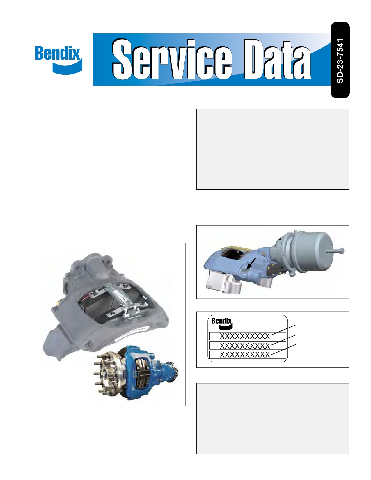
(ADB) use a floating caliper design to provide foundation
Wheel-on Inspections
6-8
braking on all axles of heavy commercial vehicles, buses
3
Troubleshooting Flowchart
9
and trailers. Bendix Air Disc Brakes provide safety and
4
Wheel-off Maintenance Inspections .
10-15
performance as well as ease of service.
5
Maintenance Kits and Procedures
16-37
The ADB22X disc brakes mount to the axle's anchor plate
Full Index - see Page 38
(torque plate) using fasteners that are installed parallel
to the axle, while the anchor-plate fasteners used for the
Bendix® ADB22X-V™ air disc brakes install at right angles
1.2 Air Disc Brake Identification
to the axle.
Locate the identification label near the guide pin housing.
See below for information about the label fields used.
Available with or without a combination spring brake unit,
these brakes may also include optional wear sensors and
wear diagnostic equipment.
Figure 2 - Typical part number label location
Bendix Part Number
Serial No.
Customer Part Number
Figure 3 - part number label information
Section One
Section
Page
1.1
Description
1
Figure 1 - Bendix® ADB22X™ Air disc Brakes
1.2
Air Disc Brake Identification
1
1.3
Rotor Identification
3
1.4
Wear Sensor Identification
3
1.5
Operation
3
1.5.1
Brake Release and Adjustment
3
1
generAl SAFety guiDelineS
WARNING: Not all wheels and valve stems
wArning! PleASe reAD AnD
are compatible with Bendix Air Disc Brakes. Use
Follow theSe inStructionS
only wheels and valve stems approved by the
to AVoiD PerSonAl inJury or DeAth:
vehicle manufacturer to avoid the risk of valve
stem shear and other compatibility issues.
when working on or around a vehicle, the following
guidelines should be observed At All tiMeS:
▲ Park the vehicle on a level surface, apply the parking
WARNING: Avoid creating
brakes and always block the wheels. Always wear
dust. Possible cancer and lung
personal protection equipment.
disease hazard.
▲ Stop the engine and remove the ignition key when
working under or around the vehicle. when working
While Bendix Spicer Foundation Brake LLC does not
in the engine compartment, the engine should be shut
offer asbestos brake linings, the long-term affects of
off and the ignition key should be removed. where
some non-asbestos fibers have not been determined.
circumstances require that the engine be in operation,
Current OSHA Regulations cover exposure levels to
eXtreMe cAution should be used to prevent personal
some components of non-asbestos linings, but not
injury resulting from contact with moving, rotating,
all. The following precautions must be used when
leaking, heated or electrically-charged components.
handling these materials.
▲ Do not attempt to install, remove, disassemble or
•
Avoid creating dust. Compressed air or dry
assemble a component until you have read, and
thoroughly understand, the recommended procedures.
brushing must never be used for cleaning brake
use only the proper tools and observe all precautions
assemblies or the work area.
pertaining to use of those tools.
•
Bendix recommends that workers doing brake
▲ if the work is being performed on the vehicle’s air brake
work must take steps to minimize exposure
system, or any auxiliary pressurized air systems, make
to airborne brake lining particles. Proper
certain to drain the air pressure from all reservoirs
procedures to reduce exposure include working
before beginning Any work on the vehicle. if the vehicle
in a well-ventilated area, segregation of areas
is equipped with a Bendix® AD-iS® air dryer system, a
where brake work is done, use of local filtered
Bendix® DrM™ dryer reservoir module, or a Bendix®
ventilation systems or use of enclosed cells with
AD-9si® air dryer, be sure to drain the purge reservoir.
filtered vacuums. Respirators approved by the
▲ Following the vehicle manufacturer’s recommended
Mine Safety and Health Administration (MSHA)
procedures, deactivate the electrical system in a manner
or National Institute for Occupational Safety and
that safely removes all electrical power from the vehicle.
Health (NIOSH) should be worn at all times during
▲ never exceed manufacturer’s recommended pressures.
brake servicing.
▲ never connect or disconnect a hose or line containing
•
Workers must wash before eating, drinking or
pressure; it may whip. never remove a component or
smoking; shower after working, and should not
plug unless you are certain all system pressure has
wear work clothes home. Work clothes should
been depleted.
be vacuumed and laundered separately without
▲ use only genuine Bendix® brand replacement parts,
shaking.
components and kits. replacement hardware, tubing,
hose, fittings, etc. must be of equivalent size, type
•
OSHA Regulations regarding testing, disposal
and strength as original equipment and be designed
of waste and methods of reducing exposure
specifically for such applications and systems.
for asbestos are set forth in 29 Code of Federal
Regulations §1910.001. These Regulations
▲ components with stripped threads or damaged parts
provide valuable information which can be utilized
should be replaced rather than repaired. Do not
attempt repairs requiring machining or welding unless
to reduce exposure to airborne particles.
specifically stated and approved by the vehicle and
•
Material Safety Data Sheets on this product, as
component manufacturer.
required by OSHA, are available from Bendix.
▲ Prior to returning the vehicle to service, make certain all
Call 1-800-247-2725 and speak to the Tech Team
components and systems are restored to their proper
or e-mail techteam@bendix.com
operating condition.
▲ For vehicles with Automatic traction control (Atc),
the Atc function must be disabled (Atc indicator
lamp should be on) prior to performing any vehicle
maintenance where one or more wheels on a drive axle
are lifted off the ground and moving.
▲ the power MuSt be temporarily disconnected
from the radar sensor whenever any tests uSing A
DynAMoMeter are conducted on a Bendix® wingman®
Advanced™-equipped vehicle.
▲ you should consult the vehicle manufacturer's
operating and service manuals, and any related
literature, in conjunction with the guidelines above.
2
1.3 Rotor Identification
1.5 Operation
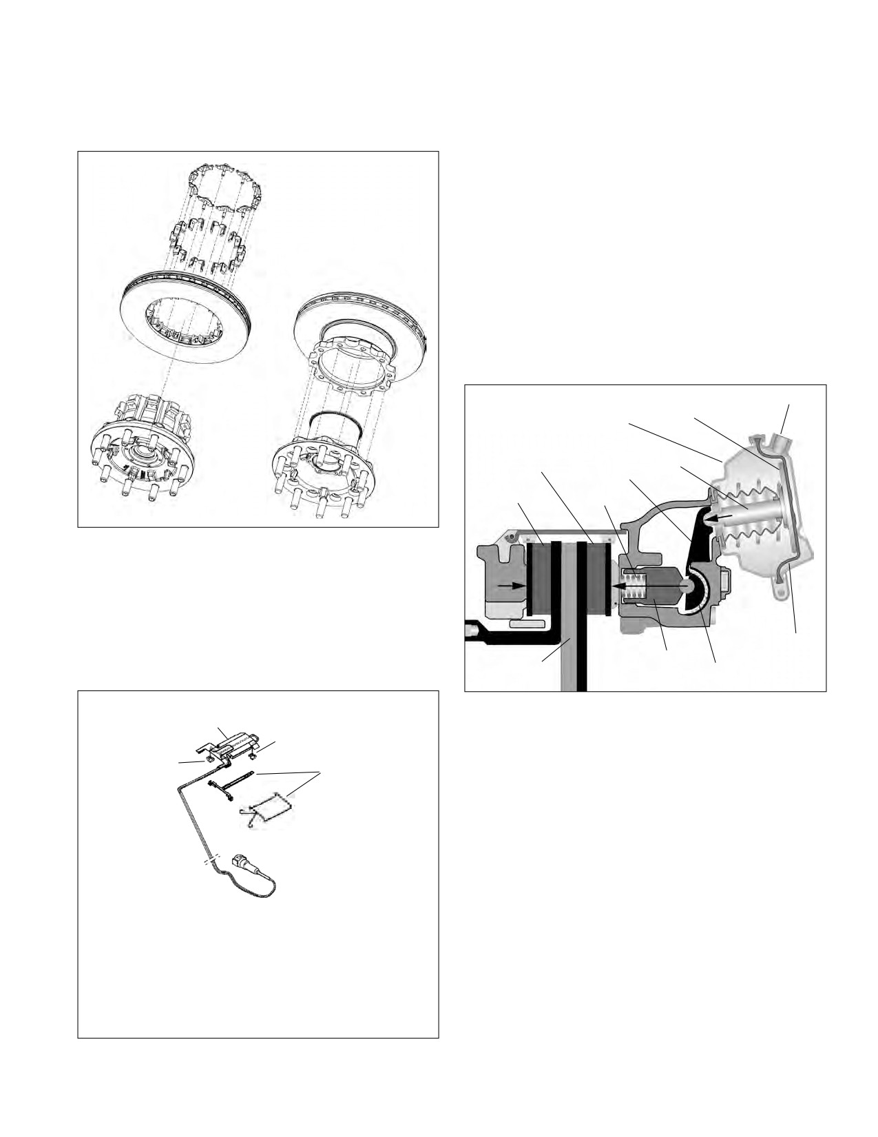
See Figure 4 to help you identify which type of rotor is used
Bendix air disc brakes convert air pressure into braking
on the axle being inspected. Note that the maintenance
force.
(See Figure 6.) When the vehicle brakes are
inspection procedure will depend on the type of rotor
applied, air enters the service brake chamber through
installed.
the supply port, applying pressure within the diaphragm.
The pressure expands the diaphragm — applying force
to, and moving, the pressure plate and push rod forward.
The push rod acts against a cup in the internal lever which
pivots on an eccentric bearing moving the bridge. Moving
against a return spring, the bridge transfers the motion to
two threaded tubes and tappets, which move the inner
brake pad. The inner brake pad (from its normal position
of having a running clearance between it and the rotor)
moves into contact with the brake rotor. Further movement
of the bridge forces the caliper — sliding on two stationary
guide pins — away from the rotor. That, in turn, pulls the
outer brake pad into the rotor. The clamping action of the
brake pads on the rotor applies braking force to the wheel.
Pressure
Supply Port
Service Brake
Plate
Chamber
Inner Brake Pad
Push Rod
Lever
Outer Brake
Pad
Return Spring
Figure 4 - rotor identification
CAUTION: Rotors may not be mixed on a single axle:
axles are only permitted to have all conventional or all
splined disc rotors.
1.4 Wear Sensor Identification
Diaphragm
See Figure 5 for the electronic wear sensor that may be
Bridge
Rotor
present.
Eccentric Bearing
104
FIGURE 6 - cross-section view showing BRAKE
Cable Protection
operation
101
Plate
Sensor
1.5.1 Brake Release and Adjustment
105
101
Cable Guide
When the vehicle brakes are released, the air pressure
Sensor
(2 alternate
in the service brake chamber is exhausted and the return
designs used)
springs in the chamber and the bridge return the air disc
brake to a neutral, non-braked position. To maintain the
running clearance gap between the rotor and the brake
pads over time, the non-braked position is mechanically
103
adjusted by a mechanism in the caliper. The adjustment
Cable to Electrical
mechanism operates automatically whenever the brakes
Supply
are activated, to compensate for rotor and brake pad wear
Sensor
101
and to keep the running clearance constant. During pad
Cable to Electrical Supply . . .
103
or rotor maintenance, the technician manually sets the
Cable Protection Plate
104
system’s initial non-braked position. The total running
Cable Guide (two designs) . . . 105
clearance (the sum of clearances on both sides of the
rotor) should be between 0.024 to 0.043 in. (0.6 to 1.1 mm).
Consult the instruction sheet included with wear
indicator kits for installation information.
Figure 5 - electronic Wear Indicator components
3
12
9
Pad
22
58
Inner Boot
7
Assembly
5
Inner Seal
1
Ring
Brass Bushing
Guide Pin
Caliper
40
Top Sectional View
Caliper Bolt
10
Cap
23
Adjuster Unit
161
Tappet Bushing
32
16
Chain Wheel
61
Threaded Tube
Shear Adapter
13
Tappet and Boot
Assembly
45 Washer
26
Spring Clip
37
Adjuster Cap
44
27 Spring
Pad Retainer Pin
30
11
Chain
Pad Retainer
17
Bridge
33
Wear Sensor
22
Inner
24
Seal
Turning
Device
161
16
Tappet
Threaded Tube
Bushing
6 Guide Sleeve
13
2
2
Tappet and
Carrier
Carrier
Boot Assembly
39
68
Caliper Bolt
Cap
58
9
4
Side Sectional View
Ring
Inner
Guide Pin
Boot
Pad Assembly 12
Short Caliper Bolt
12
18/1 Spring Brake or
Sectional View
Pad
18/2
Assembly
Brake Chamber
46
Rotor
43
Bolt
27
19
Spring
Lever
20
17
Eccentric
Bridge
Bearing
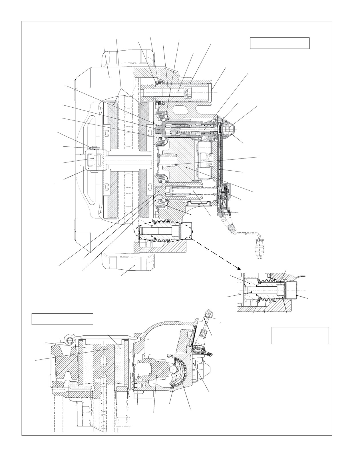
Figure 7 - sectional views
4
(Wheel turns toward
35 Double-Diaphragm Style
18/1 Spring Brake
fixed pin side of
Spring Brake Chamber
Type A
Type B
Actuator
ADB)
(Fixed pin)
44
11 Pad Retainer
Pad Retainer Pin
18/2
26 Spring Clip
Service
Actuator
12/2 Pad Holder Spring
(Pad Assembly
consists of
10
12/1 plus 12/2)
40
45
Cap
12/1 Pad
Caliper
Washer
5
Wheel Rotation
Bolt
Wheel Rotation
Guide
(typically right hand)
(typically left hand)
7
Pin
Brass
68
Bushing
Cap
Shield
22
39 Caliper Bolt
Kit
Inner Seal
161
(Drive or
Tappet Bushing
4 Guide Pin
*37 Adjuster
Actuator
Steer)
Hardware
6 Guide Sleeve
Caps (2 styles
13 Tappet
61
37*
supplied in kits)
and Boot
Shear
Assembly
Adapter
Carrier
Mounting
Hardware
1
Caliper
U-shaped Rotor
(or Caliper Kit)
9
58
Inner Boot
Ring
Bendix® ADB22X™
2B
Anchor Plate
Bendix®
(Rotor Shield for Trailers)
2
Be
ADB
U-shaped
Ca
Rotor
Fasteners
SD-
Drive Hub
SD-2
Bendix®
ADB22X-V™
Splined Disc® Rotor
Anchor Plate
SD-3
Hardware
Carrier
SD-1, -2, -3
Mounting
Hardware
See Section 5.2 for
Splined Disc® Rotor
(SD)
exploded view of electronic
wear indicator.
Steer Hub
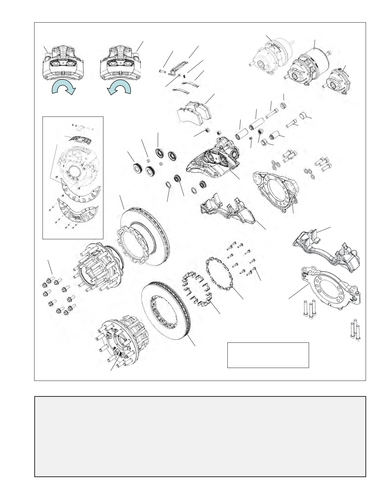
Figure 8 - exploded view - Bendix® ADB22X™ and ADB22X-V™ Air Disc Brakes
Index To Figures 7 & 8
Adjuster Caps
37
Chain Wheel
32
Pad Assembly
12
Spring Brake Actuator (Double-
Adjuster Unit
23
Cap
10
Pad Retainer
11
Diaphragm style)
35
Bolt
43
Eccentric Bearing . . .
20
Pad Retainer Pin
44
Spring Clip
26
Brass Bushing
7
Guide Pins
4, 5
Ring
58
Tappet and Boot
Bridge
17
Guide Sleeve
6
Service Actuator . . . 18/2
Assembly
13
Caliper
1
Inner Boot
9
Shear Adapter
61
Tappet Bushing
161
Caliper Bolt
39, 40
Inner Seal
22
Splined Disc Hardware
Threaded Tube
16
Cap
68
Lever
19
. . . . . .SD-1, SD-2 and SD-3
Turning Device
24
Carrier
2 (A or B)
Pad
12/1
Spring
27
Washer
45
Chain
30
Pad Holder Spring . .
12/2
Spring Brake Actuator . 18/1
Wear Sensor
33
5
Section Two: Preventive Maintenance schedule and Wheel-on inspections
2.0 Preventive Maintenance
Regular inspection and maintenance of air disc brake
components is an important part of vehicle maintenance.
Section Two
Section
Page
The maintenance practices outlined here are recommended
2.0
Preventive Maintenance
6
in addition to all standard industry practices (including
2.1
Brake Pad and Rotor Inspections
7-8
daily pre-trip inspections.) Also, see the vehicle's manual
2.2
Running Clearance Quick Inspection
8
for recommendations. Keep track of the results of your
maintenance inspections to assist you in determining the
ideal maintenance intervals for the vehicle.
Use the table below for a guide to maintenance interval
planning, however, depending on the particular vehicle's
use, more frequent checks of the components may be
necessary.
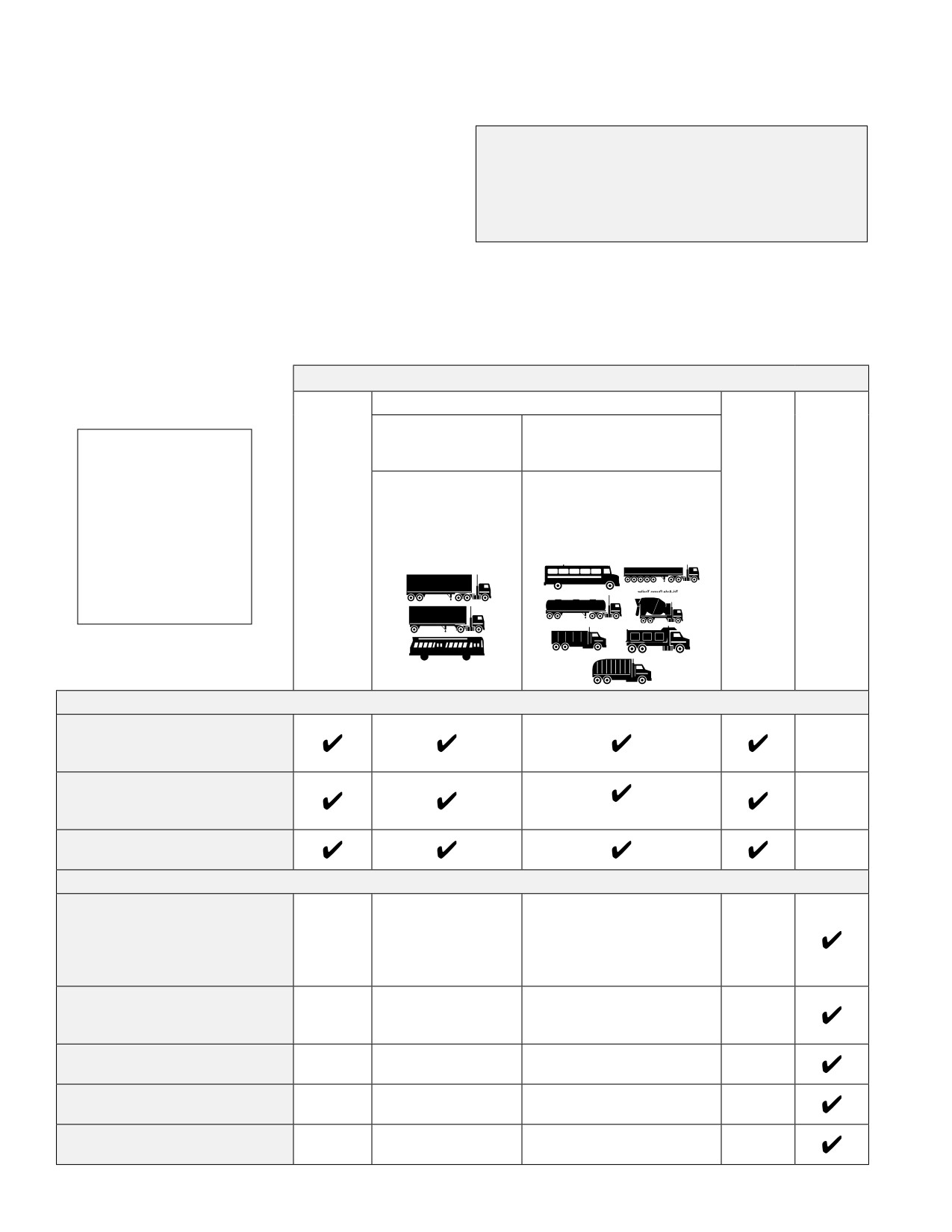
Table 1: Inspection Period
(4 to 5 times during the pad lifetime)
About every four (4)
About every three (3) months
* For vehicles with
months for over-the-
for higher-duty applications:
electronic wear
road applications:
At least
indicators, use the
e.g. pick-up & delivery,
once
dash indicator(s)
e.g. line haul, RV,
off-highway, construction,
At the
every
When
open-highway
logger, concrete mixer, dump
very
year
and/or the hand-held
you
coaches, etc.
truck, city transit bus, refuse,
least,
(and at
diagnostic tool to
check
school buses, etc.
every
every
regularly monitor the
the tire
four (4)
pad
pressures
pad wear.
months
replace-
ment)
See Section 5.2.
Inspections with the wheel mounted (Sections 2.1 - 2.3)
Inspect the pad thickness by
checking the mechanical wear
indicators*. See Section 2.1.
Inspect the running clearances
using the quick inspection
technique. See Section 2.2.
Inspect the visible part of the rotors
for cracks, etc. See Section 2.3.
Inspections with wheel removed (Section 4)
Inspect the pads and entire rotor
surfaces for cracks, etc.
(Bendix®
splined disc® rotors: Inspect
retaining hardware and check
torques) See Section 2.3.
Inspect the running clearances and
adjuster operation.
See Sections 2.2 and 4.2.
Inspect the caliper travel.
See Section 4.1.
Inspect the tappet and boot
assemblies. See Section 4.6.
Inspect all caps, hoses, and brake
exterior for damage etc.
Table 1 - Preventive Maintenance Schedule
6
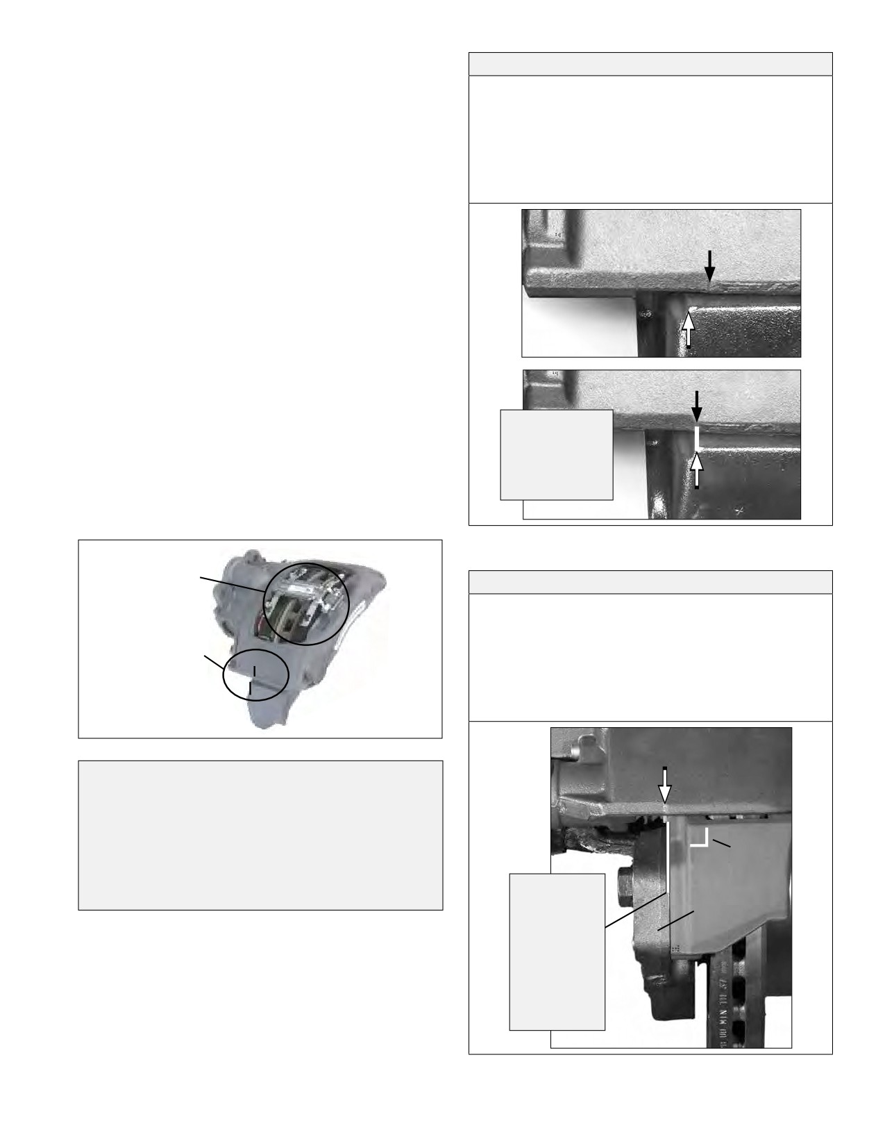
2.1 brake pad and rotor inspections
Wear Indicator Style A:
Visual checks of the condition of the brake pad/rotor wear
Where both the carrier and caliper have an
can be made without removing the wheels. Where dust
indicator notch.
guards are not used, the top of the pads and part of the
Compare the relative position of two notches cast into
rotor are visible through the opening at the top of the brake.
the carrier and caliper. When the two notches align,
Other visible portions of the rotor can be inspected at the
it is time to schedule a full wheel-removed inspection
same time.
of the pads and rotor.
Unless a vehicle has been stored for some time, the main
rotor surfaces that contact the pads will always appear to
be shiny. Surface rust on these surfaces would indicate a
Notch in the
malfunctioning brake that should be inspected immediately.
caliper
Pads are 1.181 in. (30 mm.) thick when new and must be
replaced when they reach 0.433 in. (11 mm.). Rotors are
1.77 in. (45 mm.) thick when new and must be replaced
Notch in the
when they reach 1.46 in. (37 mm.). See Section 4.3 for
carrier
further inspection criteria.
2.1.1 Electronic Wear Indicators
Use the dash indicator(s) and/or a hand-held diagnostic
When the notches
tool to regularly monitor the pad wear. (See Section 5.2.)
line up, it is time
to schedule an
2.1.2 Mechanical Wear Indicators
inspection of the
See Figure 9 for the location of the mechanical wear
pads and rotor
indicators. There are two types (See Figure 10 for Style A
and Figure 11 for Style B).
Figure 10 - Style A - when both Carrier and caliper
have a cast notch
Quick Visual
Wear Indicator Style B:
Inspection of Pad
Thickness and Rotor
Where only the caliper has an indicator
notch.
Location of Wear
When the notch in the caliper aligns with the front
Indicator Notches
edge of the torque plate, it is time to schedule a full
(Both sides of brake)
wheel-removed inspection of the pads and rotor.
Figure 9 - Location of wear indicators
Notch in
Note: These mechanical wear indicators do
the caliper
not constitute “out-of-service” criteria. These
inspections only show when to schedule a full wheel-
removed inspection of the brake pads and rotor.
No notch
The thicknesses of the pad and rotor will both affect
in the
the wear indicator position at which maintenance is
carrier
actually needed.
When the
Torque
torque plate
plate
edge lines up
with the notch,
it is time to
schedule an
inspection of
the pads and
rotor
Figure 11 - Carrier wear indicator notch and backing
plate alignment
7
F
H
•
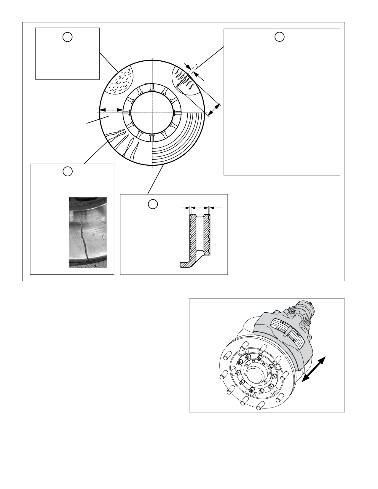
For standard Bendix rotors, cracks
No action is needed
running in a radial direction — like
for small cracks
spokes of a wheel (see Area H) — less
spread over the
Area
surface (e.g. Area F)
Area
than 0.06 in. (1.5 mm) deep or wide
F
H
are acceptable if they do not reach
either edge (see G). Cracks are only
acceptable if the length of the crack is
less than 75% of dimension “f” (the width
f
Rotor
of the rotor contact area).
Friction
•
For Bendix Splined Disc rotors, radial
Surface
cracks are only acceptable if they are
Width “f”
less than 0.04 in. (1.0 mm) deep or
wide and if they do not reach either edge
(see G). Crack lengths must be less
than 75% of dimension “f” (the width
Area G
Area J
of the rotor contact area).
G
Cracks reaching
either edge of the
rotor
are not
J
In addition, follow the
acceptable
recommendations of the
Circumferential
for either
grooves, as in Area
vehicle manufacturer.
type of
J, are acceptable
Note: Axles should
rotor
if less than 0.06 in.
have either all Bendix
(1.5 mm) deep.
Splined Disc (or all
conventional) rotors.
figure 12 - examples of acceptable and non-acceptable rotor cracks and grooves
2.1.3 Rotor Quick Inspection
See Figure 12. See the various potential rotor conditions
that you may find. See the criteria below for whether the
rotor needs to be replaced and/or scheduled for a full
inspection.
2.2 Running Clearance Quick
Inspection
CAUTION: Follow all safe maintenance practices.
Push/Pull
On level ground, with the wheels chocked and the parking
By Hand
to Check
brake temporarily released, check for movement of the
the Caliper
brake caliper. This small movement, less than 0.08" (2 mm)
Movement
- approximately the thickness of a nickel - in the inboard/
outboard direction indicates that the brake is moving
figure 13 - Caliper running clearance
properly on its guide pins.
(figure does not show wheel)
If the caliper has no movement or appears to move greater
than the distances noted above, a full wheel-removed
inspection will be necessary (See Section 4.1).
8
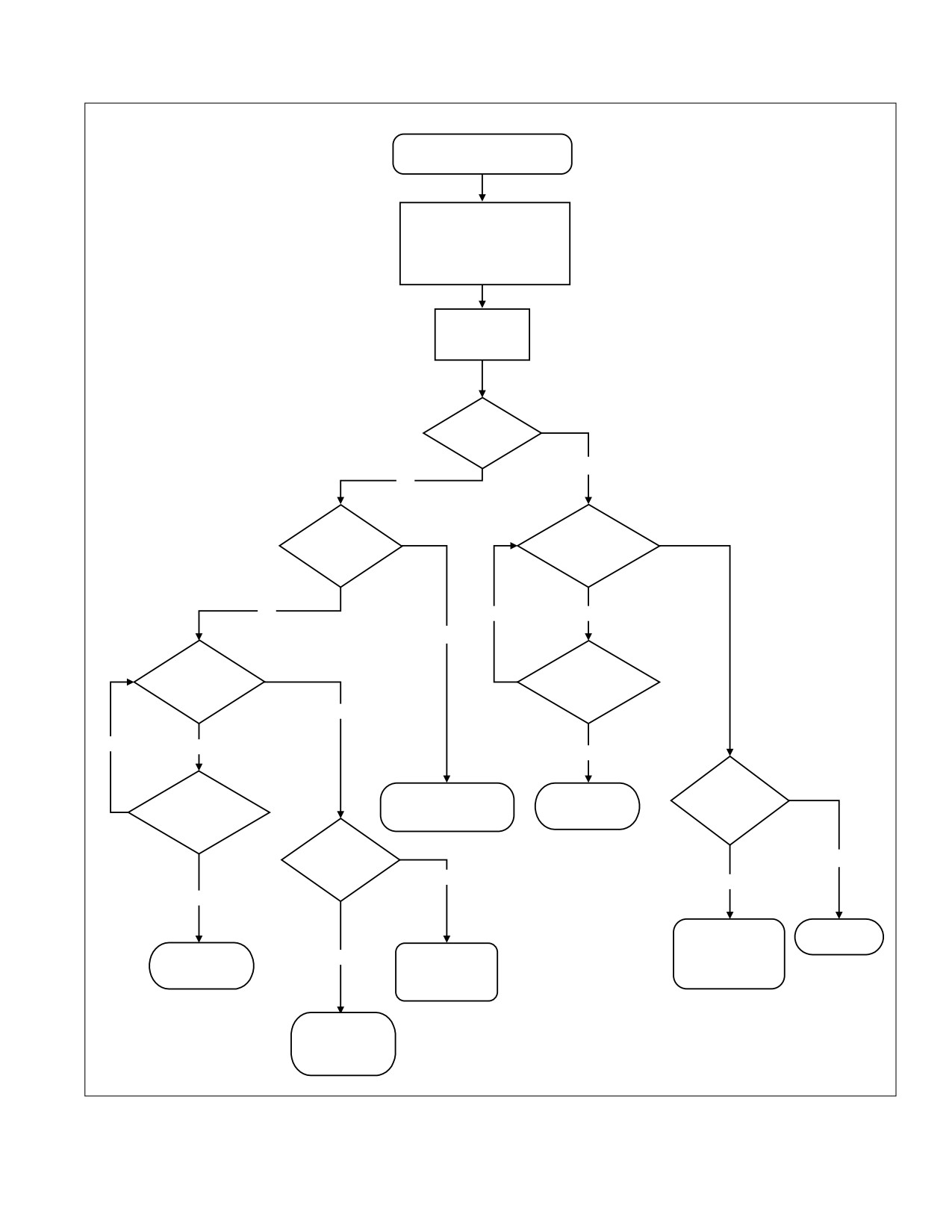
Section three: Troubleshooting Procedure Flowchart
Air Disc Brake Inspection
Follow safe maintenance practices,
chock wheels. Engage spring brakes
and cage spring. Release spring
brakes and drain air from system.
Raise axle, spin
the wheel by
hand.
Does
the wheel
turn smoothly?
YES
NO
Is
Check
the
running
YES
spring brake fully/
clearance (4.1)
partially applied?
- OK?
NO
YES
NO
YES
Check
Check
running
adjuster (4.2)
clearance (4.1)
- OK?
- OK?
YES
YES
NO
NO
Check
Drain air pressure from
Replace caliper/
Pad and rotor
Check
system. Re-start test after
carrier assembly
wear (4.3-4.4)
Adjuster (4.2)
caging spring brakes
(5.3)
- OK?
- OK?
Check
caliper
YES
guidance (4.5)
- OK?
YES
NO
NO
Replace components
Disc brake OK
Replace caliper/
as needed with
NO
Tightness not due to
carrier assembly
genuine Bendix parts.
air disc brake. See
(5.3)
vehicle manual.
Replace guide pins
(5.6) OR replace
caliper/carrier
assembly (5.3)
Figure 14 - troubleshooting Bendix air disc Brakes
9
Section four: Wheel-Off maintenance inspections
4.1 Caliper Movement Test
Section Four
CAUTION: Follow all safe maintenance practices.
Section
Page
4.0
Wheel-Off Inspections
10
Remove the wheel. With the spring brakes released or
4.1
Caliper Movement Test
10
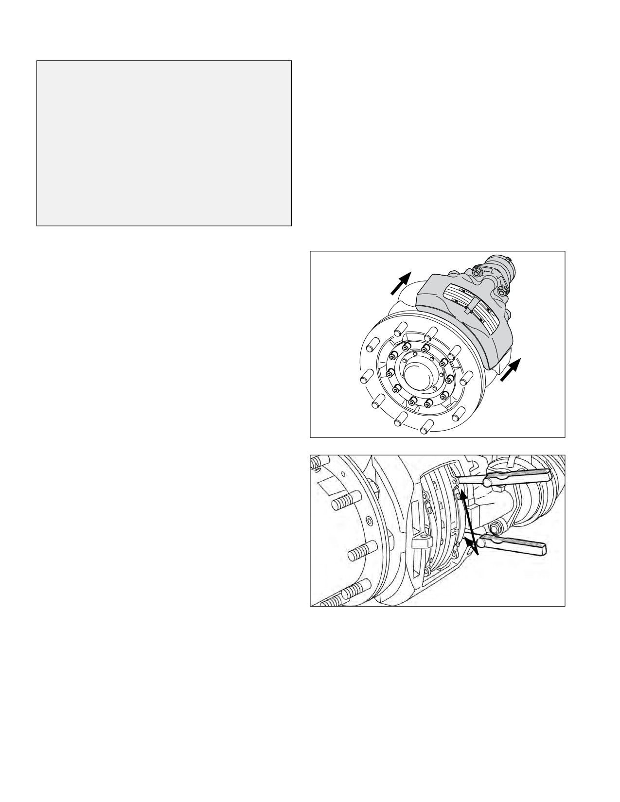
caged, push the caliper assembly inboard on its guide pins.
4.2
Adjuster Mechanism Inspection . . .
11
Note: To fully release the spring brakes, assure that the
4.3-4.4 Brake Pads and Rotors
12-14
air system pressure is at least 90 PSI. Using a suitable
4.3
Inspect the Brake Pads
12
tool (for example a large flat-blade screwdriver), press the
4.4
Inspect the Rotor
13-14
inboard pad (12) away from the tappets. Check that there
4.4.3
Machining (Grinding or Turning) Rotors
14
is no dirt, etc. in the gap, and clean if necessary. Then use
4.5
Guide Pin Bearing Inspection
14-15
two long-blade feeler gauges to measure over the whole
4.6
Tappet & Boot Assembly Inspection . .
15
tappet surface the gap between them and the inboard pad
backplate. (See Figure 16.) The gap should be between
0.024 in. (0.6 mm) and 0.043 in. (1.1 mm). If the gap is
within the range given, the test is complete.
4.0 Wheel-off inspections
CAUTION: During these inspections, follow all safe
maintenance practices, including those on page
two of this service manual. Also, follow the vehicle
manufacturer’s recommendations. When working on
foundation brakes, be sure that the vehicle is on level
ground, that the vehicle is parked by other means
than the foundation brakes, and that the wheels are
chocked.
4.0.1 Wheel Removal and Re-Installation
Pull
Caliper
Refer to the vehicle manufacturer’s recommendations for
Inboard
removing the wheel.
Note: When removing the wheel, inspect first to see that
there is no contact between the caliper and axle, vehicle,
Figure 15 - Pull Caliper inboard
chassis sections or carrier, etc. that may be impeding the
free movement of the caliper.
WARNING: Not all wheels and valve stems are
compatible with Bendix Air Disc Brakes. Use only
wheels and valve stems approved by the vehicle
manufacturer to avoid risk of valve stem shear and
other compatibility issues. After re-installing a wheel
according to the vehicle manufacturer’s recommendations,
please ensure that there is sufficient clearance between
Check the clearance at
the tire inflation valve stem, the caliper and the wheel rim,
both tappets simultaneously:
to avoid damage.
0.024 in. to 0.043 in.
(0.6 mm. to 1.1 mm.)
Figure 16 - Running Clearance Check
CAUTION: If the clearance is too wide, there is a
danger of brake failure. If the clearance is too small,
or if there is no gap at all, there is a danger of the brake
overheating. These conditions must be corrected
before returning the vehicle to service.
For further investigation, where there is some gap, go to
Section 4.2 and check the adjuster mechanism. Where
there is no movement at all (and so no gap to measure),
go to Section 4.5 “Guide Pin Inspection.”
10
4.2 adjuster mechanism Inspection
CAUTION: Follow all safe maintenance practices.
Aside from the normal maintenance schedule, the
adjuster mechanism inspection that follows is also
carried out when the Caliper Movement Test (4.1) finds
that the running clearance is too small or too large.
4.2.1
With the spring brake released (or caged), remove
the adjuster cap (37) using the tab, taking care not
Figure 20 - Backing-off (increasing) the Running
to move the shear adapter (61). Note: One of two
Clearance
styles of adjuster cap (stamped metal or plastic
If the shear adapter fails, you may attempt a second time
adjuster cap) may be used.
with a new (unused) shear adapter.
Note: Always double-check that the spring brake is released
(where applicable) if a shear adapter fails; if this step was
missed, the shear adapter will break off, and it may appear
that the caliper is seized.
In cases where a second failure of the shear adapter
confirms that the adjustment mechanism is seized, the
caliper must be replaced.
Adjuster Cap
Location
Figure 17 - adjuster cap location
37
Figure 21 - Applying moderate applications of the
Cap
brakes: the
wrench moves clockwise as the running
clearance is diminished
4.2.3
Where the adjuster mechanism is able to be backed-
23 Adjuster
off normally, position a box-end wrench on the shear
61 Adapter
adapter so that it can turn clockwise freely without
37
coming into contact with parts of the vehicle (See
Cap
Tab
Tab
Figure 21). Make five to ten moderate applications
of the brakes [at about 30 psi (2 Bar)], and observe
Figure 18 - Exploded view
Figure 19 - CAP INSTALLED:
of adjuster and adapter
tab location
that the box-end wrench or socket should turn
clockwise in small increments.
For illustration purposes, the exploded view (Figure 18)
shows the adjuster (23) and shear adapter (61) separated.
NOTE: As the number of applications increases,
the turning movement will decrease (as the brake
When using the adjuster mechanism, always have the
shear adapter installed on the adjuster.
reaches its normal calibration point).
4.2.2
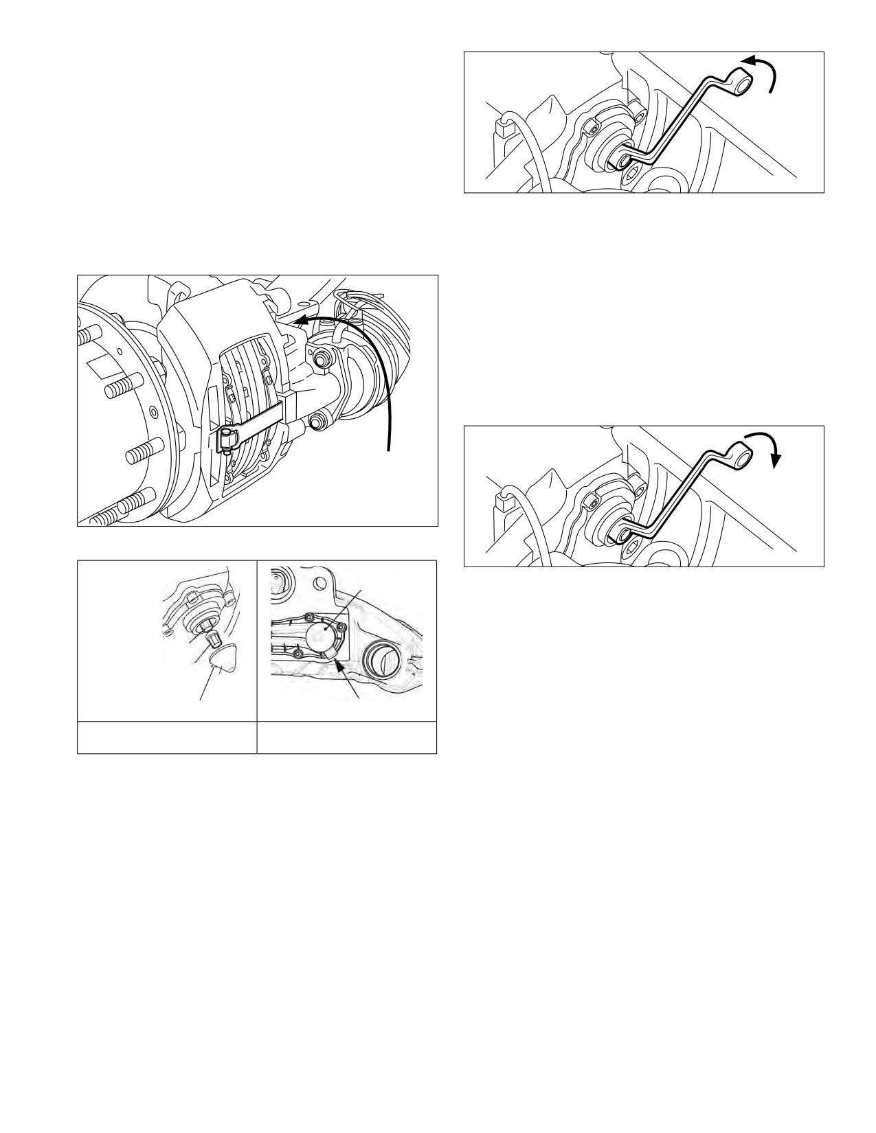
Using a 10 mm. six-point box wrench, turn the Shear
If the box-end wrench does not: (a) turn at all; (b) turns only
Adapter (61) counter-clockwise and listen for
with the first application; or (c) turns forward and backward
the sound of 3 clicks as the mechanism backs-off
with every application, the automatic adjuster has failed and
(increases) the running clearance. Note: Do not
the caliper/carrier assembly must be replaced.
use an open-ended wrench as this may damage
After completing these wheel-off tests, Bendix recommends
the adapter. See Figure 20.
installing a new adjuster cap (lightly greased using white,
CAUTION: Never turn the adjuster (23) without the
lithium-based grease) when returning the brake to service.
shear adapter (61) installed. The shear adapter is a
Ensure that the tab is in the position shown in Figure 19.
safety feature and is designed to prevent excessive
torque from being applied to the adjuster. The shear
adapter will fail (by breaking) if too much torque is
applied.
11
4.3- 4.4 Brake Pads and Rotors
4.3 Inspect the Brake Pads
CAUTION: Follow all safe maintenance practices.
Regular inspection of the brake pads (even for vehicles
that use an electronic wear indicator) is an important part
If electronic wear sensors are present, see Section 5.2.
of vehicle maintenance.
If dust covers are present, see Section 5.1.
4.3.1
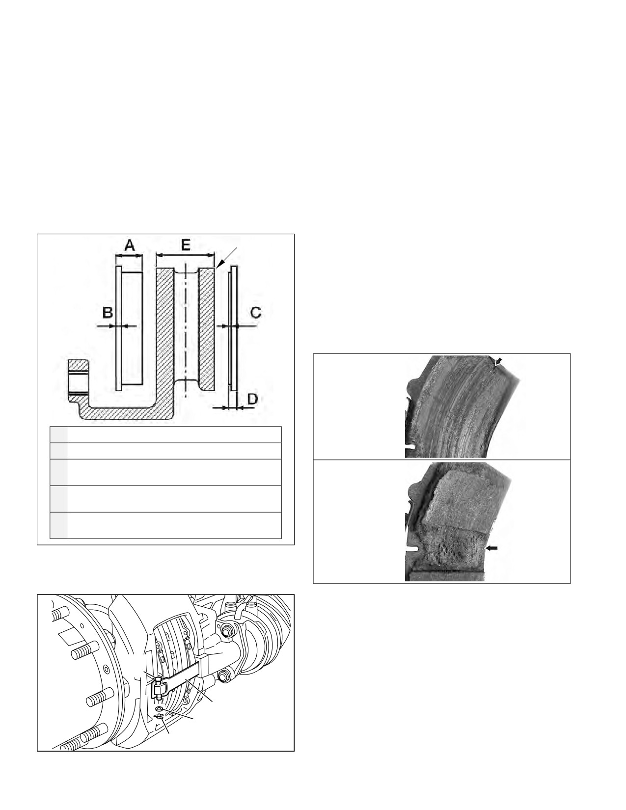
See Figure 22. If the thickness of the friction
See Figure 23. While pressing down against the pad
material — dimension “C” — is less than 0.080 in.
retaining bar (11), remove and retain the clip (26),
(2 mm.), the pads must be replaced.
washer (45) and pin (44). Remove the pad retainer bar (11).
Bendix® ADB22X™, ADB22X-V™ air disc brakes use 0.35 in.
Bendix recommends that these items should be replaced
(9 mm.) backing plates, so dimension “D” (the combined
with new (See available kits and parts, Section 5.0).
pad and backing plate thickness) must be a minimum of
0.43 in. (11 mm.).
Follow the steps in Section 4.2 for backing-off the adjuster
mechanism. Slide the caliper inboard then outboard to
4.3.2
Check for uneven end-to-end pad wear. If the
difference in wear is greater than 0.080 in. (2 mm.),
permit easy removal of the brake pads.
replace the brake pads and also inspect the guide
pins (See Section 4.5).
Brake Rotor
4.3.3
Compare the thickness of the inboard and outboard
Outboard
pads of each set. If the difference between the
Brake Pad
inboard and outboard pad thickness is greater than
0.138 in. (3.5 mm.), replace the brake pads and
inspect the guide pins (See Section 4.5).
If the results of the pad inspections are within the acceptable
range, inspect the pad surface. (See Figure 24).
Inboard
Brake Pad
Where a
small amount
of brake
Minor Damage -
material
Is Acceptable
chipped from
the edge
A
Thickness of a new pad (1.181 in.) (30 mm.).
B
Backing plate thickness (0.360 in.) (9 mm.)
C
Minimum thickness of friction material (0.080 in.)
(2 mm.)
D
Minimum thickness of a worn pad (0.433 in.)
(11 mm.); replace pads.
Major Damage -
E
Thickness of a new rotor (1.77 in.) (45 mm.).
Is Not Acceptable
Minimum rotor thickness (1.46 in.) (37 mm.)
Section
damaged or
Figure 22 - PAD AND ROTOR DIMENSIONS
missing
See Figure 22 for initial brake pad and rotor dimensions,
as well as minimum acceptable dimensions.
Figure 24 - brake PAD surface inspection
Minor damage at the edges is permitted, but replace the
pads if major damage on the surface of the pad is found.
When replacing brake pads, Bendix strongly recommends
that all the brake pads on an axle be replaced at one time.
44
See Section 5.1 for the pad replacement procedure. Also
Pin
see the vehicle manufacturer’s recommendations found in
the operator’s manual.
11 Pad Retainer Bar
45 Washer
26 Spring Clip
Figure 23 - Retainer bar removal
12
Bendix air disc brakes are precision-engineered braking
4.4.1
Measure the thickness of the brake rotor at the
mechanisms. The “friction couple” braking characteristics
thinnest point (Dimension “E” in Figure 22). Avoid
have been carefully optimized — and the rotor design and
measuring near the edge of the rotor as minor
materials have been matched with special formulation
burrs may result in inaccurate measurement. For
brake pads for optimal performance. In all cases, use
Bendix® brand rotors, replace the rotor when
brake pads with the type of backing plate and lining material
the minimum thickness of 1.46 in. (37 mm.) is
originally supplied by the vehicle manufacturer.
reached. For other brands of rotors, refer to the
rotor manufacturer’s guidelines.
CAUTION: When replacing brake pads and rotors,
use only Bendix® brand replacement pads and rotors
4.4.2
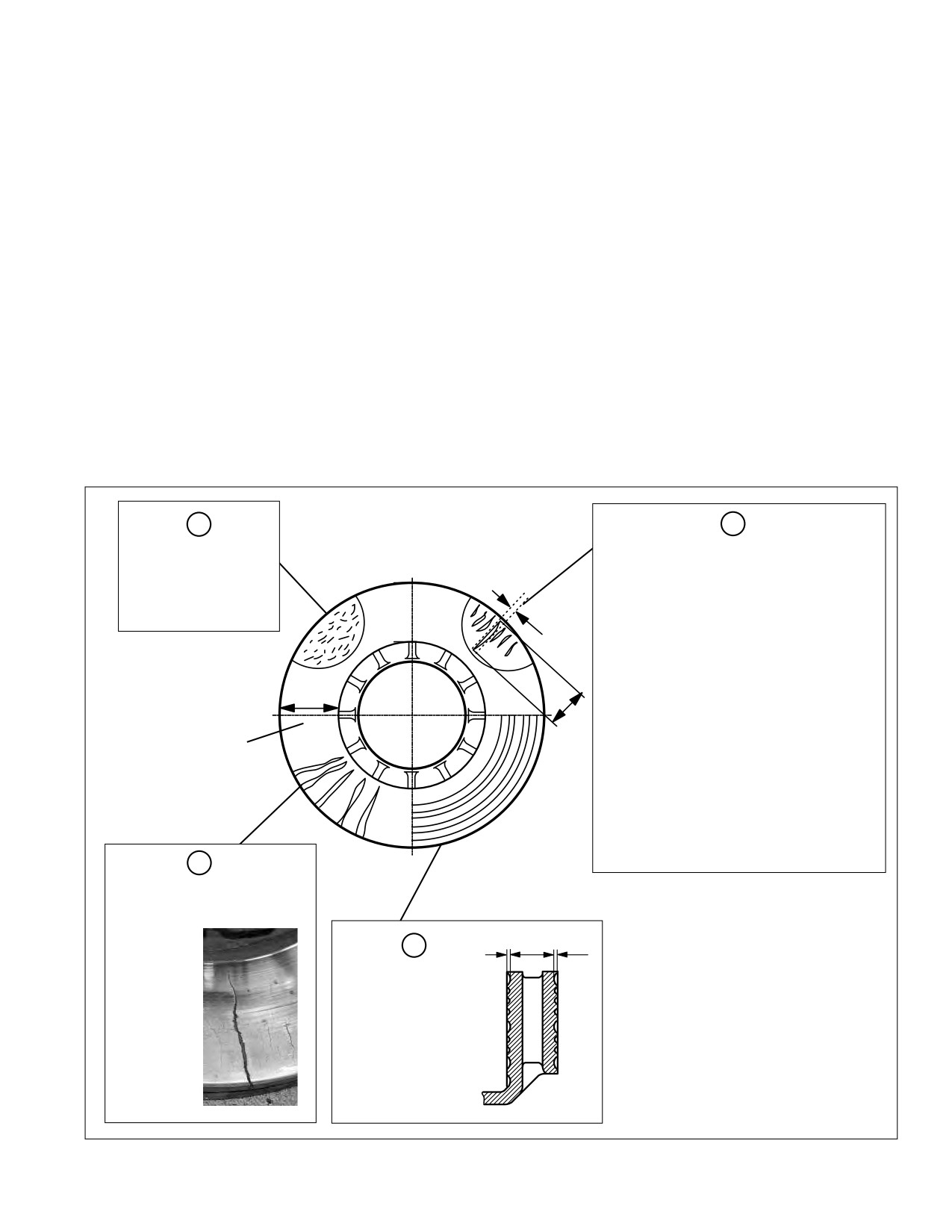
Inspect the rotor surface. See Figure 25. The type
and/or those approved by the OEM. Non-approved
of rotor, and also the size, depth and direction of
replacement disc pads or rotors can cause excess
the imperfections, must all be considered.
wear to brake components, and can increase the risk
Note: If surface wear conditions F through J are
of rotors cracking, etc.
in the permitted range, the rotor is still usable until
it reaches the minimum acceptable thickness for the
4.4 Inspect the Rotor
rotor manufacturer’s guidelines.
CAUTION: Follow all safe maintenance practices.
4.4.3 Machining (Grinding or Turning) Rotors
Identify if the rotor is a Bendix® Splined Disc®, or Bendix®
Bendix® brand rotors are normally service-free. In the case
brand conventional rotor (See Section 1.03). Rotors should
of severe grooving of the entire friction surface, however,
be inspected regularly (See Section 2.0 for recommended
conventional rotors may be turned when changing
inspection schedule) and at each pad change.
pads, to increase the load-bearing surface.
F
H
•
For standard Bendix® brand rotors,
No action is needed
for small cracks
cracks running in a radial direction —
like spokes of a wheel (see Area H)
spread over the
Area
surface (e.g. Area F)
Area
— less than 0.06 in. (1.5 mm) deep or
F
H
wide are acceptable if they do not reach
either edge (see G). Cracks are only
acceptable if the length of the crack is
less than 75% of dimension “f” (the width
f
Rotor
of the rotor contact area).
Friction
•
For Bendix® Splined Disc rotors,
Surface
radial cracks are only acceptable if they
Width “f”
are less than 0.04 in. (1.0 mm) deep
or wide and if they do not reach either
edge (see G). Crack lengths must be
less than 75% of dimension “f” (the
Area G
Area J
width of the rotor contact area).
G
Cracks reaching
either edge of the
rotor
are not
J
In addition, follow the
acceptable
recommendations of
Circumferential
for either
the vehicle and rotor
grooves, as in Area
type of
manufacturer.
J, are acceptable
rotor
if less than 0.06 in.
Note: Axles should
(1.5 mm) deep.
have either all Bendix
Splined Disc (or all
conventional) rotors.
Figure 25 - examples of acceptable and non-acceptable rotor conditions
13
Machining of Bendix® Splined Disc® rotors is
5
7
not permitted.
1
9
Guide Pin
Brass Bushing
Caliper
Inner Boot
CAUTION: Always maintain air disc brake pads and rotors
within specifications. Excessive pad or rotor wear will
10
degrade braking performance.
Cap
long
bearing side
Periodic inspection of the Bendix Splined Disc attachment
hardware is recommended to ensure optimum braking
performance. Bendix recommends verifying the torque on
the spring element fasteners whenever a brake inspection
is performed.
WARNING! After machining/turning,
the minimum rotor thickness for Bendix®
brand rotors must be at least 1.535 - 1.575 in.
(39 - 40 mm.) - for other brands, consult the
manufacturer’s guidelines. Also, Check the
vehicle manufacturer’s recommendations.
short
Failure to comply may result in brake failure
bearing side
and in serious injury or death. MACHINING of
Bendix splined disc rotors is not permitted.
4.4.4 Rotor Replacement
An axle is permitted to have only all Bendix Splined
Disc, or all conventional, rotors.
When replacing rotors, be sure to adhere to the vehicle
6 Guide Sleeve
manufacturer’s recommendations, including bolt tightening
Caliper
torques. It is recommended to install only Bendix® brand
Movement
Outboard
Inboard
rotors, and also that the pads should be replaced (as an
axle set) at the same time.
39
68
Caliper Bolt
Cap
Non-Bendix® brand rotors. If a non-Bendix® brand rotor is
4 Guide Pin
9 Inner Boot
used, confirm that it complies to the vehicle manufacturer’s
recommendations.
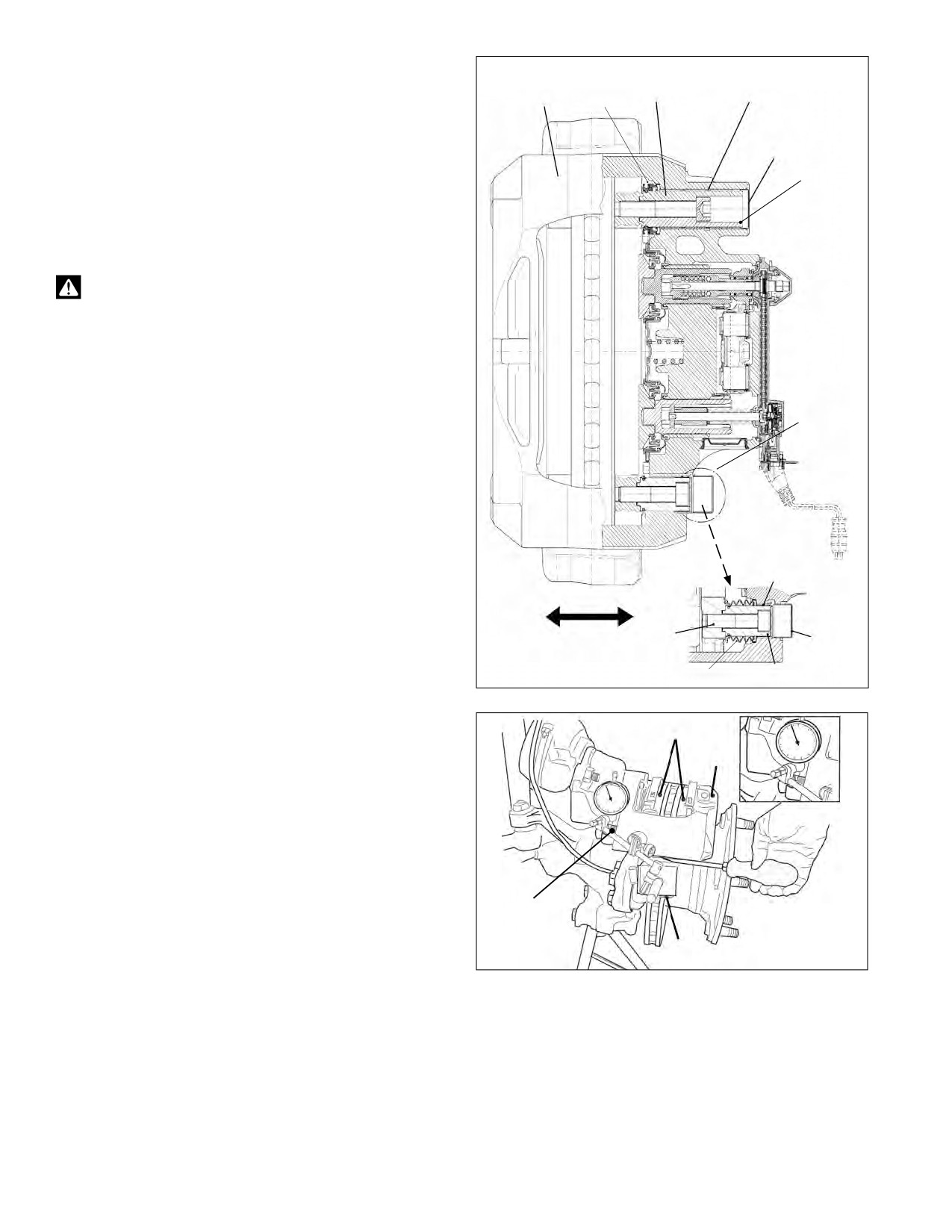
Figure 26 - guide pins
CAUTION: The use of non-approved brake rotors may
12 Pad Assembly
1
reduce levels of safety and invalidate the warranty.
Carrier
See Section 5.7 for re-installation procedures.
4.5 Guide Pin Bearing Inspection
CAUTION: Follow all safe maintenance practices.
This guide pin inspection should be carried out if the
technician cannot move the caliper during a Caliper
Magnetic
Movement Test (Sections 2.2 and/or 4.1).
Dial-Gauge
Measures
Measure the range of travel along the guide pin
Range Here
2
Caliper
bearings:
Figure 27 - Magnetic dial-gauge in use
4.5.1
Remove the Pads (See Section 4.3). Using hand
pressure only (no tools), the caliper (1) should slide
Measure the “play” (range of movement) in the guide
freely along the whole length of the guide pins. This
pin bearings:
movement should be at least 0.95 inch (25 mm)
4.5.2
See Figures 26 and 27. With the wheel removed,
when the pads are not present. If the movement
remove the pad retainer bar (11). Temporarily
is less than this amount, replace the caliper/carrier
replace the pads with two new pads (12). Attach
assembly.
a magnetic dial-gauge holder to the carrier (2) on
the short bearing side of the caliper (1). Use the
measuring point on the caliper (1) - see the callout
14
in Figure 27. Press the caliper in the direction of
4.6 Tappet and Boot Assembly
the carrier (2) and set the dial-gauge to zero.
Inspection
4.5.3
Place a suitable tool (e.g. a large flat-blade
4.6.1
In order to inspect the tappet and boot assembly,
screwdriver) between carrier (2) and caliper (1) and
remove the pads (12) (See Sections 4.3 or 5.2) and
use light hand force to move the caliper away from
advance the shear adapter (61) clockwise.
the carrier, until the movement stops. Read the
CAUTION: Never extend the tappet more than
maximum value on the dial-gauge. See Figure 27.
1.75 in. (44.5 mm). See Figure 29. Over-extending the
If the value is greater than 0.039 in. (1.0 mm), replace
tappet will result in the tappet losing engagement with
the guide pin bushings (See Section 5.6) OR replace the
the synchronizing mechanism. Since the mechanism
caliper/carrier assembly (See Section 5.3).
can only be set at the manufacturing plant, the caliper/
carrier assembly must be replaced if this happens.
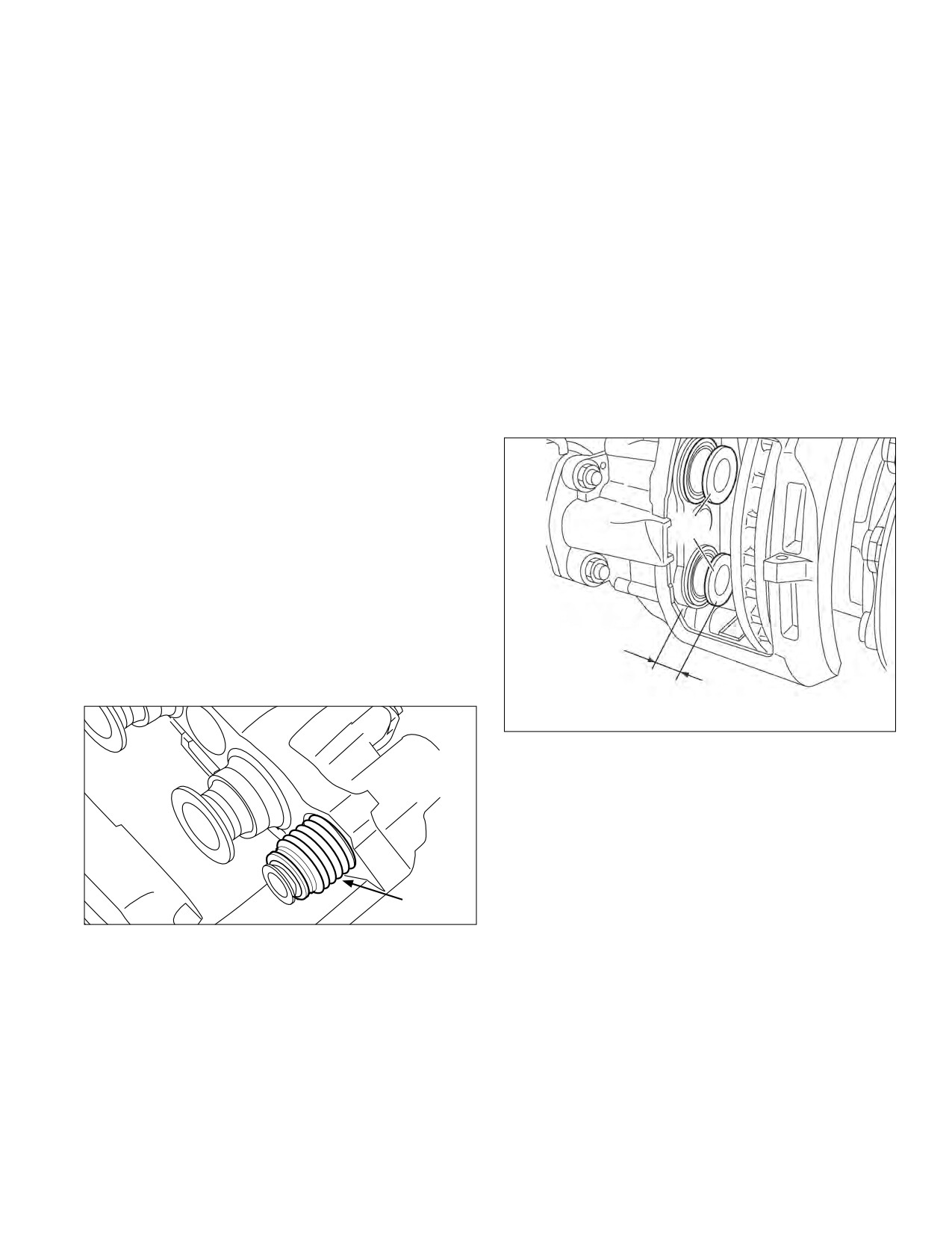
Inspect the guide pin inner boots:
4.6.2
Inspect the tappet and boot assemblies
4.5.4
See Figures 28 and 29. With the pads removed,
(13) for evidence of damage, cuts,
slide the carrier by hand to the inboard position (See
cracks, tears and evidence of
Figure 28). By looking through the opening where
corrosion, etc. Damaged boots lead to the
the pads are installed — and also from below —
penetration of dirt and moisture, and can lead to
inspect the inner boot (9) for each of the guide pins.
corrosion and impair the operation of the brake.
Inspect for damage, cuts and cracks.
Replace as necessary (See Section 5.5).
Replace damaged boots immediately to prevent
dirt and/or moisture affecting the movement of the
guide pins (See Section 5.4). Damaged or corroded
guide pins will impair the operation of the brake.
In addition, during installation, the boots are
compressed to minimize the amount of air trapped
13
within them. Observe as you move the carrier back
towards the outboard position; the boots should only
expand outwards a small amount due to trapped
air. The boots should normally (due to their ribbed
construction) contract back into place as the caliper
moves on the guide pins. The boots are not air-
tight and so some trapped air is normal; excess air
trapped will dissipate.
Extend LESS THAN
1.75 in. (44.5 mm.)
Figure 29 - permitted tappet extension
Where the tappets and boots pass the inspection, retract
the tappets using the shear adapter.
When installed, the boots are compressed to minimize the
amount of air trapped within them. Observe as you move
the tappet back using the shear adapter; the boots should
only expand outwards a small amount due to trapped air.
Inspect
The boots should normally (due to their ribbed construction)
Boot
contract back into place as the tappets move. Note: If the
bellows have excess air trapped, then with the tappets
Figure 28 - Guide pin boot inspection (this image does
not show the carrier)
retracted, remove and re-install the actuator to vent the
4.5.5
Inspect the original pads (See Section 4.3) and they
excess trapped air (See Section 5.4).
may be reused if they are in good condition with
Follow the reinstallation steps for the brake pads (See
sufficient pad thickness.
Section 5.2).
15
Section five: Maintenance Kits and procedures
Section Five
Section
Page
Section
Page
5.0
Maintenance Kits
16-18
5.4
Spring/Service Brake
24
5.1
Air Disc Brake Shield Kit
19
5.5
Tappet & Boot, and Tappet Inner Seal
25-28
5.2
Pad Replacement
20
5.6
Guide Pin and Boot Assemblies . .
29-34
5.3
Caliper/Carrier/Actuator Assembly
22-23
5.7
Bendix® Splined Disc® Hub Rotor
35-37
(Wheel turns toward
35
fixed pin side of
18/1 Spring Brake
Type A
Type B
Actuator
ADB)
(Fixed pin)
44
11 Pad Retainer
Pad Retainer Pin
18/2
26 Spring Clip
Service
Actuator
12/2 Pad Holder Spring
(Pad Assembly
consists of
10
12/1 plus 12/2)
40
Cap
45
12/1 Pad
Caliper
Washer
5
Bolt
Wheel Rotation
Wheel Rotation
Guide
(typically right hand)
(typically left hand)
7
Pin
Brass
68
Bushing
Cap
Shield
22
39 Caliper Bolt
Kit
Inner Seal
161
(Drive or
Tappet Bushing
4 Guide Pin
*37 Adjuster
Actuator
Steer)
Hardware
Caps (2 styles
13 Tappet
61
37*
6 Guide Sleeve
supplied in kits)
and Boot
Shear
Assembly
Adapter
Carrier
Mounting
Hardware
1
Caliper
U-shaped Rotor
(or Caliper Kit)
9
58
Inner Boot
Ring
Bendix® ADB22X™
2B
Anchor Plate
Bendix®
(Rotor Shield for Trailers)
2
Be
ADB
U-shaped
Ca
Rotor
Fasteners
SD-
Drive Hub
SD-2
Bendix®
ADB22X-V™
Splined Disc® Rotor
Anchor Plate
SD-3
Hardware
Carrier
SD-1, -2, -3
Mounting
Hardware
See Section 5.2 for
Splined Disc® Rotor
exploded view of electronic
(SD)
wear indicator.
Steer Hub
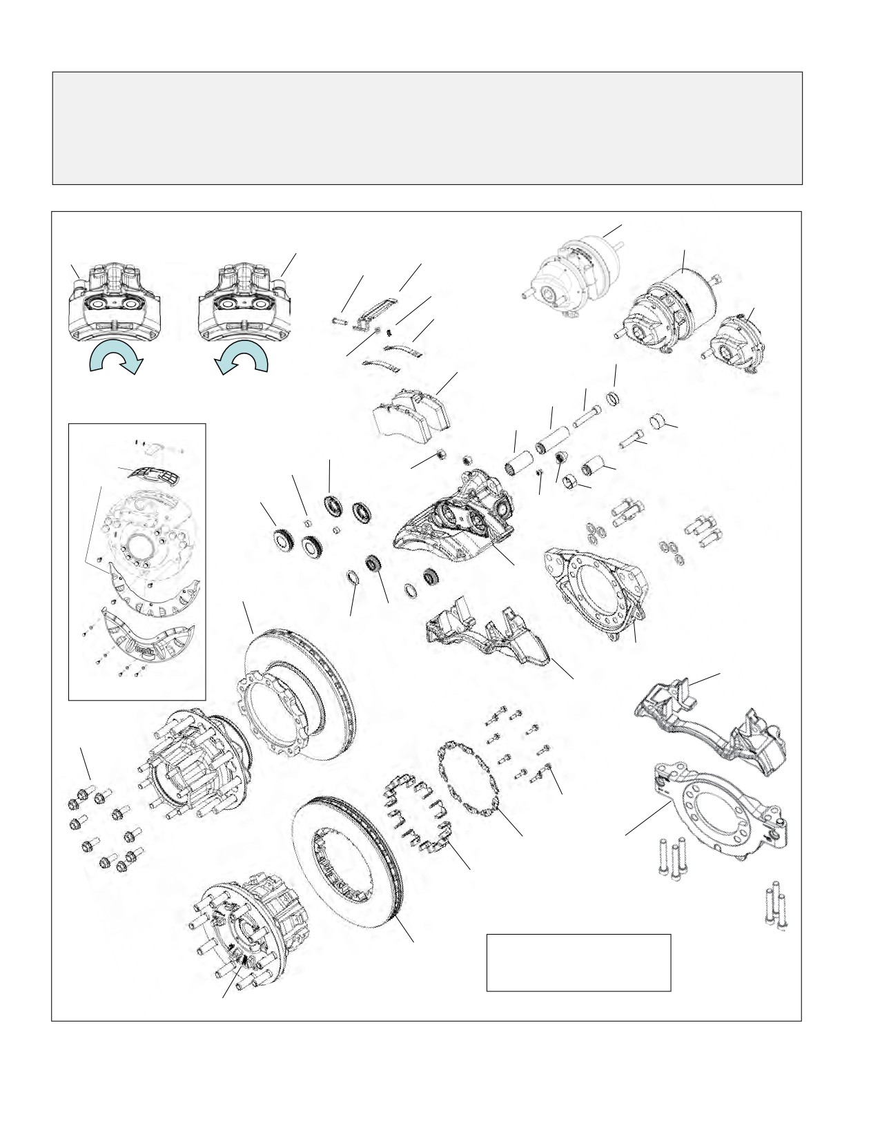
Figure 30 - exploded view - Bendix® ADB22X™ and ADB22X-V™ Air Disc Brakes
16
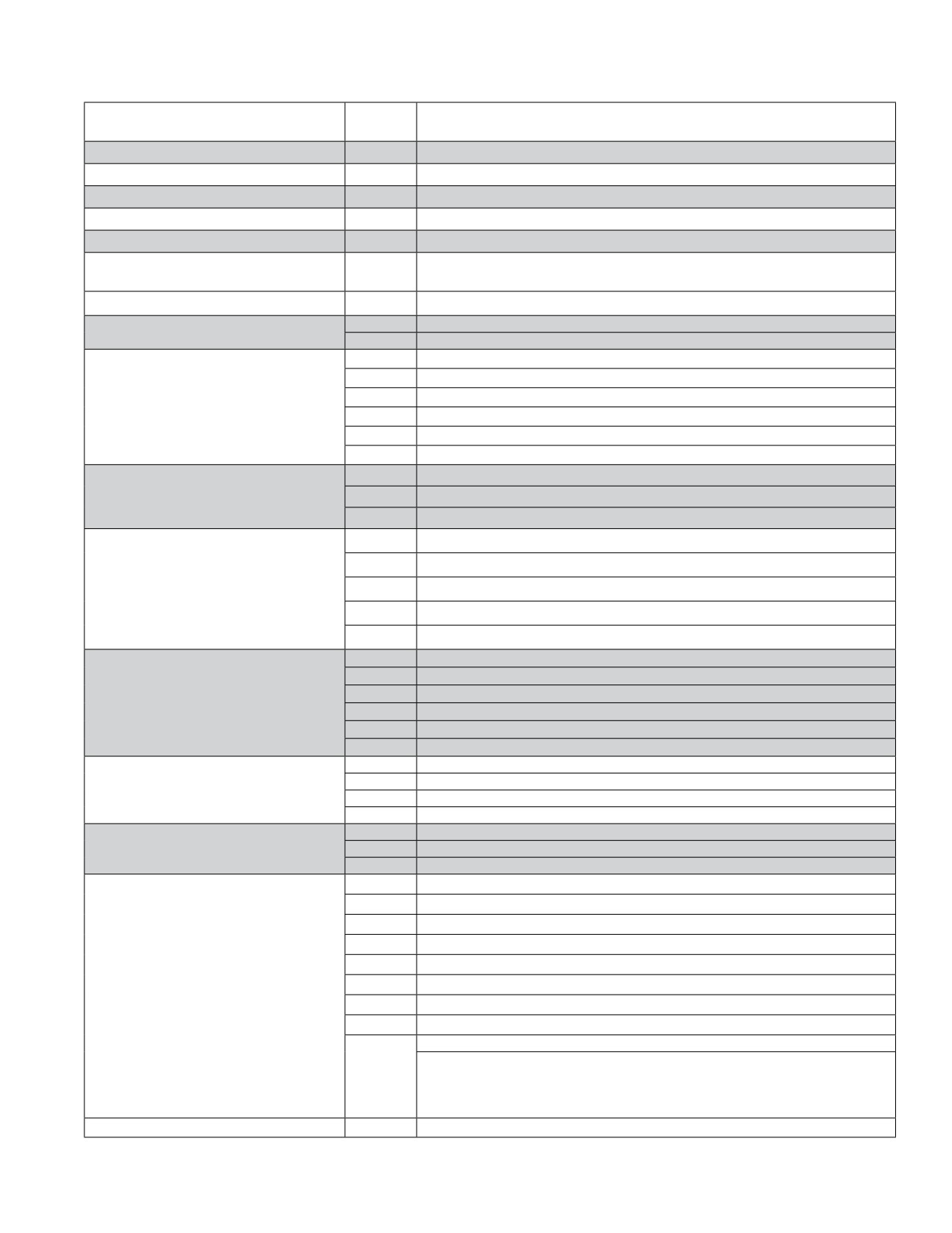
5.0 Maintenance Kits for Bendix® ADB22X™ and 22X-v™ Air disc Brakes
Below is a list of some of the available kits. See Figure 30 for an exploded view showing the components listed.
Piece
Kit
Components Included in Kit
Number
Pad Kit (axle set)
K070796
(11, 12/1, 12/2, 26, 37, 44, 45, 61)
Splint Kit (box of 25)
803151
(26)
Shear Adapter (box of 10)
802455
(61)
Tappet/Boot Kit (wheel end kit)
K092079
(13, 22, 161)
Adjuster Cover (box of 10)
802643
(37)
Guide Pin, Seal and Boot Kit
803114
(4, 5, 6, 7, 9, 10, 37, 39, 40, 58, 61, 68)
(wheel end kit)
Guide Pin Boot Kit
K023768
(9, 10, 37, 39, 40, 58, 61, 68)
II14525
White (5 grams)
Guide Pin Grease
K021964
White (500 grams)
K028039
Bendix® Type 14 Universal (9, 18/2)
K028226
Bendix® Type 16 Universal (9, 18/2)
K028022
Bendix® Type 18 Universal (9, 18/2)
Service Actuators
K028225
Bendix® Type 20 Universal (9, 18/2)
K028238
Bendix® Type 22 Universal (9, 18/2)
K028252
Bendix® Type 24 Universal (9, 18/2)
K027557
Bendix® Type 18/16 Piston Style Truck/Trailer Universal (1, 18/1)
NG-3 Piston Style
K025670
Bendix® Type 18/24 Piston Style Truck/Trailer Universal (1, 18/1)
Spring Brake Chambers
K025669
Bendix® Type 20/24 Piston Style Truck/Trailer Universal (1, 18/1)
K042457
Bendix® Type 16/24 Double Diaphragm Style (35)
K043329
Bendix® Type 18/24 Double Diaphragm Style (35)
Double-Diaphragm Style
K041960
Bendix® Type 20/24 Double Diaphragm Style (35)
Spring Brake Chambers
K043148
Bendix® Type 22/24 Double Diaphragm Style (35)
K043270
Bendix® Type 24/24 Double Diaphragm Style (35)
K081142
12 Degree Steer and Drive Axial “A” (2A, 1)
K081143
12 Degree Steer and Drive Axial “B” (2A, 1)
Caliper-Carrier Assembly
802984
Zero Degree Trailer Axial “A” (2A, 1) [Zero degree dual-beam carrier.]
(Includes 803114)
802985
Zero Degree Trailer Axial “B” (2A, 1)
K081256
12 Degree Steer and Drive Vertical “A” (2B, 1)
K081257
12 Degree Steer and Drive Vertical “B” (2B, 1)
K081258
12 Degree Steer and Drive Axle “A” (1)
Caliper Kit
K081259
12 Degree Steer and Drive Axle “B” (1)
(rationalized)
K019180
Zero Degree Trailer Axle “A” (1)
Includes 803114
K019181
Zero Degree Trailer Axle “B” (1)
K051853
Steer and Drive Axle, Axial (2A, 9, 10, 20, 39, 40, 58, 61, 68)
Carrier Kit
K043288
Trailer Axle, Axial (2A, 9, 10, 20, 39, 40, 58, 61, 68)
K056559
Steer and Drive Axle, Vertical (2B, 9, 10, 20, 39, 40, 58, 61, 68)
K020505
Splined Disc® Brake - Aluminum - FF Steer, LMS Bearing Package (Steer Hub)
803134
Splined Disc® Brake - Aluminum - FL Steer, LMS Bearing Package (Steer Hub)
802847
Splined Disc® Brake - Aluminum - R Drive, LMS Bearing Package (Drive Hub)
K020514
Splined Disc® Brake - Aluminum - FF Steer, Standard Bearing Package* (Steer Hub)
803138
Splined Disc® Brake - Aluminum - FL Steer, Standard Bearing Package* (Steer Hub)
802859
Splined Disc® Brake - Aluminum - R Drive, Standard Bearing Package* (Drive Hub)
Hubs
K045298
Splined Disc® - Aluminum - "TN" Trailer, Standard Bearing Package* (Drive Hub)
K045297
Splined Disc® - Aluminum - "TP" Trailer, Standard Bearing Package* (Drive Hub)
See hub
U-shaped - Iron/Aluminum, LMS/Standard Bearing Packages
supplier
for these
standard
Flat - Iron/Aluminum, LMS/Standard Bearing Packages
hub
products
Bendix® Splined Disc® Rotor Attaching Kit
K037767
All Splined Disc® Rotor Applications (SD-1, SD-2, SD-3)
Table 2 - Maintenance Kits
(Continues over)
17
Piece
Kit
Components Included in Kit
Number
802081
Severe Duty 138mm U-shaped Rotor and Fasteners
K038573
Heavy Duty 138mm U-shaped Rotor and Fasteners
802082
Severe Duty 150mm U-shaped Rotor and Fasteners
Rotors
K038574
Heavy Duty 150mm U-shaped Rotor and Fasteners
802083
Severe-Duty Splined Disc Kit (SD-1, SD-2, SD-3, SD)
802569
Heavy-Duty Splined Disc Kit (SD-1, SD-2, SD-3, SD)
803129
(Dana) Trailer Axle Pad & Rotor Shield Kit
803130
Axial Drive Axle Pad & Rotor Shield Kit
Shields
802948
Pad Shield Kit
K032135
Vertical Drive Axle Pad & Rotor Shield Kit
k022168
Vertical Drive Axle Rotor Shield
Table 2 - Maintenance Kits (continued)
See the Bendix Quick Reference Catalog (BW1114) for maintenance kits for other Bendix® brand Air Disc Brakes.
5.0.1 General information about
•
When replacing bearings — or for any other
maintenance procedure where the technician needs
Bendix® air DISC brake maintenance
to remove the caliper/carrier assembly from the vehicle
When working on Bendix® Air Disc brakes, please note
to perform the maintenance — replacement caliper/
the following:
carrier bolts will be required. Please note that due
•
Read and follow the Safe Maintenance Practices on
to the high torque required, the original bolts cannot
page two.
be reused. The bolts are available from the vehicle
manufacturer.
•
Depending on the particular axle, the technician may
need to remove the caliper/carrier to allow sufficient
•
WARNING: Not all wheels and valve stems are
access to perform the work.
compatible with Bendix Air Disc Brakes. Use only
wheels and valve stems approved by the vehicle
•
CAUTION: When using a hoist to support the air
manufacturer to avoid risk of valve stem shear and
disc brake, do not attempt to use the pad retainer
other compatibility issues.
bar as a bracing point as it is not designed to
support the weight of the brake. Instead use a
5.0.2 Service DVD
brace (or chain) wrapped around the entire brake
Order part number BW7356 for a DVD showing the full
to attach the hoist.
set of maintenance procedures included in this Service
Data sheet.
Remove Caliper/
Remove
Remove
Carrier from
Actuator from
See
Brake Pads?
Kit
Vehicle?
Caliper?
Section
Section 5.2
Section 5.3
Section 5.4
Dust Shields
Section 5.1
Not Typically
NA
NA
Pad Kit (axle set)
Section 5.2
Yes
No
No
Caliper Kit (rationalized)
Section 5.3
Yes
Yes
Yes
Carrier Kit
Section 5.3
Yes
Yes
Yes
Service Actuator
Section 5.4
No
Not Typically
Yes
Spring Brake Actuator
Section 5.4
No
Not Typically
Yes
Tappet/Boot Kit (wheel end kit)
Section 5.6
Yes
Typically
Typically
Guide Pin, Seal and Boot Kit (wheel end kit)
Section 5.7
Yes
Typically
Typically
Hubs
Section 5.8
Yes
Yes
Yes
Splined Disc® Rotor Attaching Kit
Section 5.9
Yes
Yes
Yes
Rotor
Section 5.10
Yes
Yes
Yes
Table 3 - Other required sections for Maintenance kits
18
5.1 Air disc brake shield kit
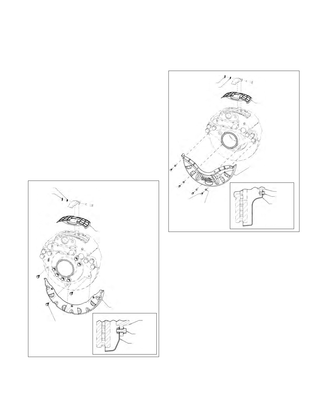
5.1.2
Remove and discard the spring clip and washer
from the pad retainer pin. Remove and retain the
5.1.1
CAUTION: Follow all safe maintenance
retainer bar and retainer pin. Position the pad shield
practices, including those listed on page two of
as shown and re-insert the retainer bar. Install
this document. Park the vehicle (by other means
the retainer pin. Use the included spring clip and
than the foundation brakes) on level ground and
washer to secure the retainer pin. Check that the
chock the wheels.
pad shield is held securely in place by the retainer
Note: Most torque plates manufactured after January 1,
bar. See Figure 31 or 32.
2007 have the required torque plate tabs to permit these
Spring
shields to be mounted.
Clip
This shield kit includes a brake pad shield, a rotor shield
Washer
and the required attaching hardware for use in Bendix®
ADB22X™ and ADB22X-V™ Air Disc Brake applications
Pad Shield
where external contamination and excessive road debris is
a concern. Brake pad and rotor shields can greatly reduce
damage and/or premature wear of pads and rotors under
these conditions.
During installation, verify that once the shield(s) are
installed they will not come into contact with any vehicle
components, suspension, housings, etc. through the full
range of motion of the wheel. Keep in mind the particular
use of the vehicle, the orientation of the brake on the axle
Rotor Shield
and torque plate, the proximity of other axles, and/or the
wheel/tire being used.
Washer
Torque
Plate
Spring
Fastener
Clip
(with Washer)
Fastener
Rotor
Lock
Shield
Washer
Pad Shield
Figure 32 - Trailer Axle Exploded view with inset
showing rotor shield installation
5.1.3
Drive or Steer Axle Rotor Shields (See Figure
31). Position the rotor shield between the torque
plate and the rotor. The supplied cap screws
pass through the mounting tabs in the torque plate
and install into the shield. Torque cap screws to
44 Ft. Lbs. (528 in. lbs.).
5.1.4
Trailer Axle Rotor Shields (See Figure 32).
Position the rotor shield with the torque plate
between the shield and the rotor. With one
Rotor Shield
(supplied) lock washer in place on each cap screw,
pass the screws through the shield before mounting
Fastener
Torque
Plate
onto the threaded torque plate holes. Torque the
cap screws to 24 ft. lbs. (288 in. lbs.).
Fastener
Note: The installation of air disc brake shields does not
Rotor Shield
eliminate the need for periodic maintenance and inspection
of the air disc brake and entire wheel end for damage and/
or wear. In addition, the truck and trailer manufacturer’s
Figure 31 - Drive or Steer Axle Exploded view with
inset showing rotor shield installation
specific criteria for the brake shield requirements on air
disc brakes should be consulted before either installing or
removing air disc brake shields from a wheel end(s).
19
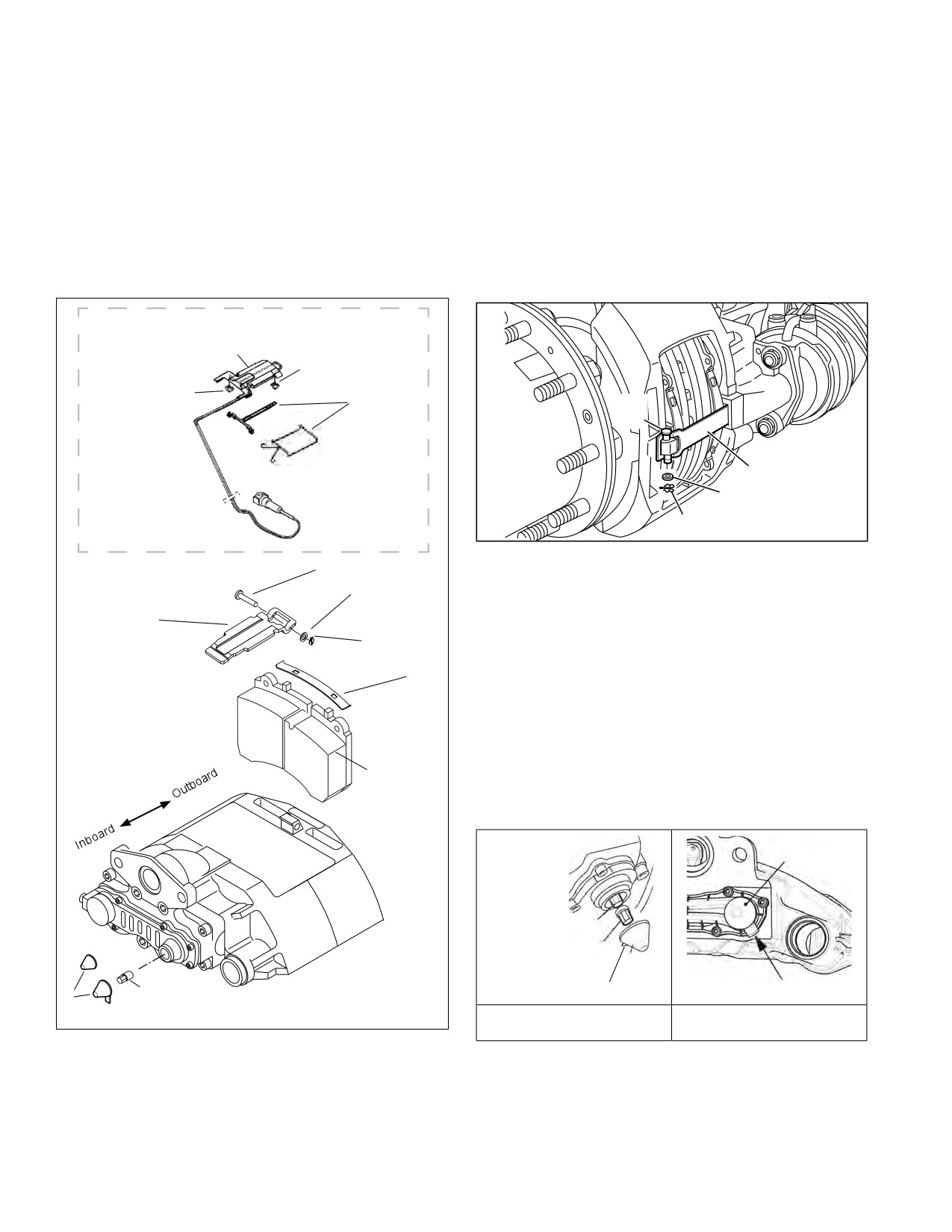
5.2 Pad Replacement
and retain the mounting hardware for the cable
5.2.1
CAUTION: Follow all safe maintenance
protection plate. The cable protection plate can
practices, including those listed on page two of
then be set aside while servicing the pads. Note the
this document. Park the vehicle (by other means
position of the sensors in the brake pad channels,
than the foundation brakes) on level ground and
and carefully remove them. In most cases you do
chock the wheels.
not need to release the cable connector in order to
The Bendix DVD (BW7356) shows this procedure.
move the sensors away from the pad installation
work area. Inspect the wear sensors - replace if
Important: If the vehicle is equipped with spring brakes,
damaged or abraded.
cage the spring brakes on all axles to be worked on.
Consult the vehicle manufacturer’s instructions as
5.2.4
See Figure 34. Remove and discard the pin
necessary. For Bendix piston-style, see Section 5.4.
retention clip (26) and washer (5).
ELECTRONIC WEAR
SENSOR
104
(if installed)
Cable Protection
101
Plate
Sensor
105
101
Cable Guide
Sensor
(2 alternate
44
designs used)
Pin
11 Pad Retainer Bar
45 Washer
103
Cable to Electrical
26 Spring Clip
Supply
Figure 34 - Pad retainer bar removal
44
5.2.5
While pressing against the pad retainer bar, remove
45
the pin (11). Discard the pad retainer bar.
11
5.2.6
With the spring brake released (or caged), remove
26
the adjuster cap (37) using the tab, taking care not
to move the shear adapter (61). Note: Two sizes
2
of adjuster cap are supplied in kits; use the same
size as before in step 5.2.20.
5.2.7
Inspect the shear adapter (61). If significant
corrosion and/or damage is present, remove the
adjuster adapter using needle-nose pliers and
12
replace with the adapter supplied in the kit and
clean as necessary.
37
Cap
23 Adjuster
61 Adapter
37
Cap
61
Tab
Tab
37
Figure 35 - Exploded view
Figure 36 - CAP INSTALLED:
of adjuster and adapter
tab location
Figure 33 - Pad replacement
For illustration purposes, the exploded view (Figure 35)
5.2.2
Raise the complete axle to be worked on until the
shows the adjuster (23) and shear adapter (61) separated.
tires clear the ground. See the vehicle maintenance
When using the adjuster mechanism, always have the
manual instructions for removing the wheels.
shear adapter installed on the adjuster.
5.2.3
If the air disc brake is equipped with an electronic
wear sensor indicator (see top of Figure 33), remove
20
CAUTION: Never turn the adjuster (23) without the
Use these two inspections:
shear adapter (61) installed. The shear adapter is a
A. Check for uneven end-to-end pad wear. If
safety feature and is designed to prevent too much
the difference in wear is greater than 0.080 in.
torque being applied. The shear adapter will fail (by
(2 mm.), replace the brake pads and also inspect
breaking) if too much torque is used.
the guide pins (See Section 4.5).
Note: For wheel-ends with spring brakes, if a shear adapter
B. Compare the thickness of the inboard and
fails, always double-check to verify that the spring brake
outboard pads of each set. If the difference
has been released (or caged). If the spring brake is applied,
between the inboard and outboard pad thickness
release or cage the brake (assure that the air system
is greater than 0.138 in. (3.5 mm.), replace the
pressure is at least 90 PSI) and start the procedure again.
brake pads and inspect the guide pins (See
If the shear adapter fails, you may attempt a second time
Section 4.5).
with a new (unused) shear adapter. In cases where a
5.2.12 Inspect the Brake Rotor (See Section 4.4).
second failure of the shear adapter confirms that the
5.2.13 Inspect the guide pins (See Section 4.5).
adjustment mechanism is seized, the caliper must be
replaced.
Important: To maintain optimal braking, Bendix
5.2.8
Use a 10 mm., six-point box wrench (See Figure 37)
strongly recommends that whenever brake pads
are replaced, the complete axle set be replaced
to turn the adjuster counterclockwise until sufficient
space exists to remove the brake pads. A clicking
together. Use only pads which are permitted by the
vehicle manufacturer, axle manufacturer, and/or disc
noise occurs each time the adjuster turns.
brake manufacturer. Failure to comply with this may
Caution! Avoid overloading or damaging the adjuster
invalidate the vehicle manufacturer’s warranty.
shaft. Do not use an open-ended wrench since it may
Before installing the brake pads, use the adjuster to
damage the adjuster shaft.
fully retract the tappets to provide adequate clearance.
5.2.14 Clean the surfaces that will come in contact with
the brake pad.
Caution: When installing pads and retaining springs,
where appropriate, use heavy duty gloves and always
keep fingers away from potential pinch hazard areas.
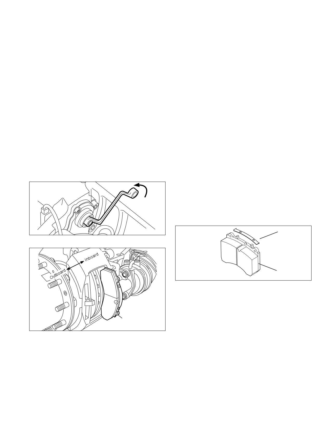
2
Figure 37 - backing off the Adjuster for pad removal
12
Figure 39 - Pad Retaining Spring Installation
5.2.15 Install the pad retaining springs(2) onto the brake
pads(12) by inserting one end of the spring onto
the lug at the top of the brake pad (See Figure 39).
Carefully apply enough force to permit the second
Inboard Pad
lug to fully engage, taking care to keep fingers etc.
away from the spring as it seats.
Figure 38 - Pad removal
5.2.16 Pull the caliper fully outward and install the outboard
5.2.9
See Figure 38. Move the caliper fully inward and
pad. Move the caliper fully inward and install the
remove the inboard pad, then move the caliper fully
inboard pad.
outward and remove the outboard pad.
5.2.17 To reinstall wear indicators (if used): Insert the
5.2.10 Repeat the pad removal procedure for the other
wear sensors into position in the new brake
end of the axle.
pads. Route the sensor cable through the cable
protection plate channel and secure the plate with
5.2.11 To confirm that the guide pins are sliding freely,
the mounting hardware retained at disassembly.
examine the pads just removed for uneven wear.
(See Section 5.2.)
21
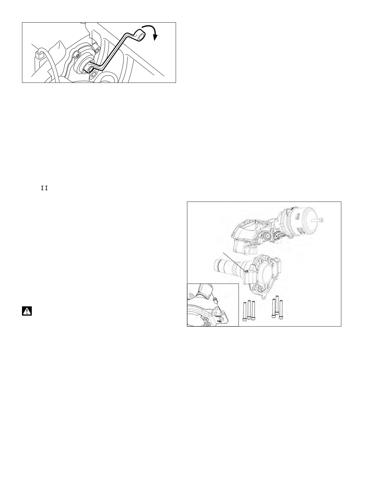
5.3 Caliper/carrier/actuator
assembly
CAUTION: Follow all safe maintenance practices,
including those listed on page two of this document.
Park the vehicle (by other means than the foundation
brakes) on level ground and chock the wheels.
CAUTION: When using a hoist to support the air disc
brake, do not attempt to use the pad retainer bar as a
Figure 40 - Running Clearance Adjustment
bracing point. It is not designed to support the weight
5.2.18
Using a 10 mm., six-point box wrench, turn the
of the brake. Use instead a brace (or chain) wrapped
Shear Adapter (61) clockwise until the pads contact
around the entire brake to attach the hoist.
the rotor. Note: Do not use an open-ended wrench
5.3.1
In all cases check that the current hose routing
as this may damage the adapter. (See Figure 40).
arrangement does not restrict the full travel of the
5.2.19
Using the same tool, turn the Shear Adapter (61)
caliper before beginning work on the assembly.
counter-clockwise and listen for the sound of 3
5.3.2
Remove the brake pads (See Section 5.2).
clicks as the mechanism backs-off (increases) the
running clearance. (See Figure 37).
5.3.3
(See Section 5.4). If the actuator used is a spring
brake, following the manufacturer’s guidelines, cage
5.2.20
Select the correct replacement adjuster cap from
the spring. With all air pressure drained from the
those supplied with the kit. Lightly grease adjuster
system, disconnect the air hoses from the brake
cap with Renolit HLT2 white grease (part number
chamber.
14525) and install the cap.
Vertical Mounting Bolt Style
5.2.21
Push the new pad retainer bar (11) into the groove
of the caliper. Press down on the pad retainer bar,
Caliper/Carrier Assembly (Showing
and insert the pad retainer pin (44), with the pin
Spring Brake Actuator )
pointing downwards, where possible. Install the
supplied washer (45) and then the spring clip (26).
(See Figure 34).
5.2.22
Apply and release the brakes. The hub should
Alignment
Bushing
turn easily by hand after applying and releasing the
Anchor Plate/
brake.
Torque Plate
5.2.23
Re-check the running clearance. Readjust if
necessary.
5.2.24
Reinstall the wheel, following the vehicle manual
Alignment
Bushing
instructions.
Mounting Bolts
(6 total - washers
WARNING!
not required)
The brake pads and rotor must be maintained within
the recommended wear limits. Failure to monitor wear
Figure 41 - vertical mount caliper/carrier
and replace the brake pads and rotor when required
5.3.4
See Figure 41. Supporting the air disc brake by
may result in diminished brake performance.
necessary means, remove the six (6) mounting
bolts/washers and discard. Note: Bendix strongly
recommends that during re-assembly these bolts
are replaced - see your vehicle manufacturer for
replacement hardware. Lift the caliper up off the
anchor plate.
The vertical bolt assembly includes an alignment bushing.
This bushing must be saved for re-use during re-
assembly of the brake. The bushing mounts in the torque
plate and maintains the correct alignment of the brake
assembly relative to the rotor.
22
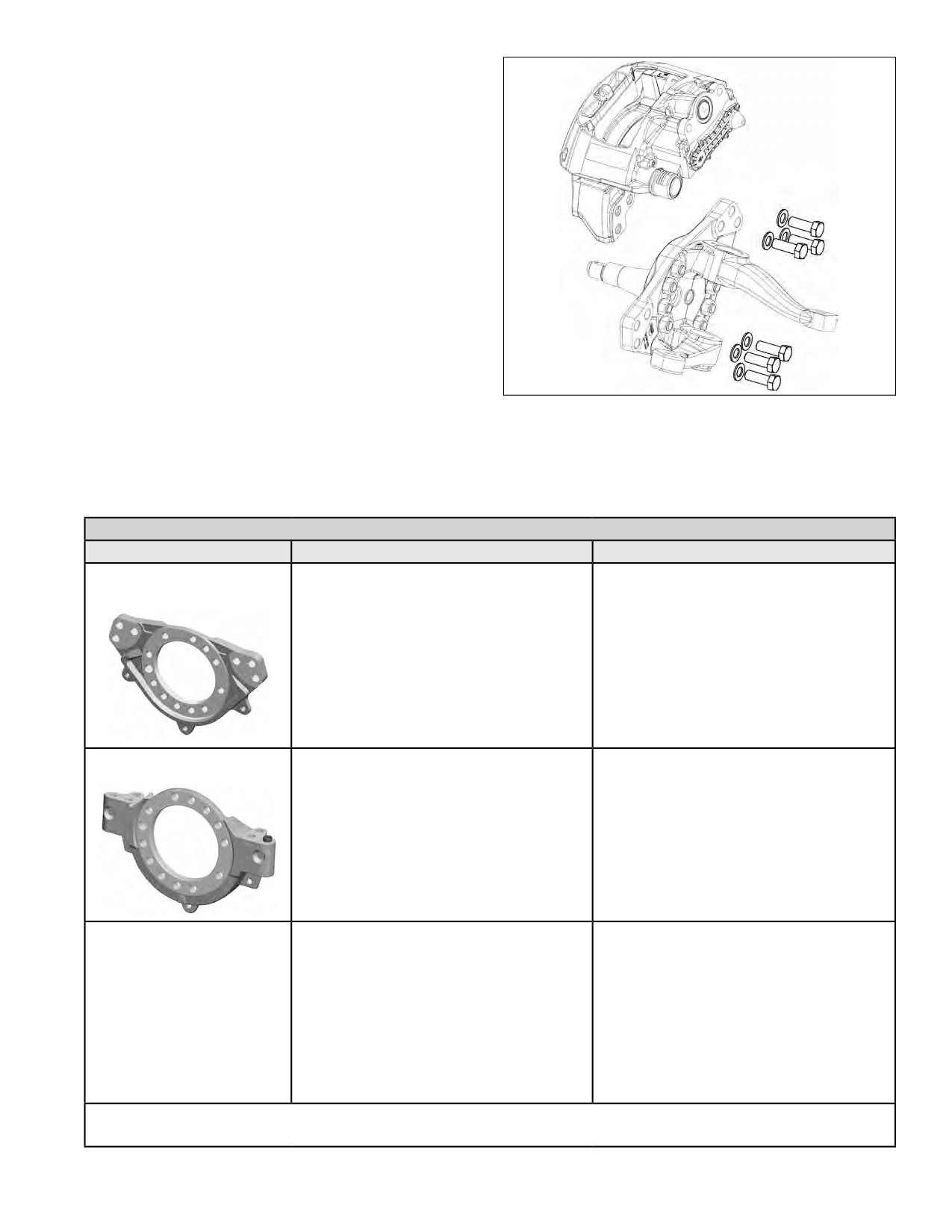
5.3.5
If the brake assembly does not separate from the
anchor plate it may be helpful to install an M16X2.0
Caliper/Carrier
screw longer than 120 mm at the bushing locations
Assembly
(Actuator not
and tap the end of the bolt with a hammer to free
shown)
the brake assembly. Remove the assembly.
Axial Mounting Bolt Style
Mounting Bolts
5.3.6
Disconnect the air hose(s) to the brake chamber.
and Washers
(6 sets total)
See Figure 42. Supporting the air disc brake by
necessary means, remove the six bolts attaching
the brake to the anchor plate and remove the
caliper/carrier assembly from the vehicle.
Note: Bendix strongly recommends that during re-assembly
these bolts and washers are replaced. See your vehicle
Anchor Plate/
Torque Plate
manufacturer for replacement hardware. Remove the
assembly.
Re-installation (Both Styles)
5.3.7
Supporting the air disc brake by necessary means,
Figure 42 - Axial mount caliper/carrier
attach the brake to the anchor plate using six
5.3.8
Re-install the air hoses (See Section 5.4.8-9) and
(new) bolts. Torque to vehicle manufacturer’s
check for leaks.
specifications. If torque values and bolts are not
specified by the vehicle manufacturer, then select
5.3.9
Inspect and re-install the pads (See Section 5.2).
a replacement bolt as shown in Table 4.
Air Disc Brake Attachment Hardware
Torque Plate Manufacturer
Fastener
Torque
Bendix Axial
Fastener: M20 x 2.5 x 60 mm Class 10.9
Carrier Torque Plate
Washer: Requires a THROUGH
Use the manufacturer’s recommendations.
HARDENED 3 mm (minimum thickness) for
each bolt.1 If the vehicle is using a Bendix
If unavailable, use phosphate
and oil finish fastener.
manufactured Axial Anchor Plate, with a
thickness of 1.14 in. (29 mm) where these
Pre-Torque: 20-60 ft-lbf [27-81 N·m]
bolts are assembled, then a bolt with an
overall length of 2.36 in. (60 mm) will meet
Final Torque: 350-400 ft-lbf [475-542 N·m]
these requirements
Bendix Vertical
Carrier Torque Plate
Use the manufacturer’s recommendations.
Fastener: M16 x 2.0 x 110 mm, Class 10.9
If unavailable, use plain and oil finish fastener.
Washer: None required.
Torque: 200-220 ft-lbf [271-298 N·m]
Fastener: M20 x 2.5 x L Class 10.9
Use the manufacturer’s recommendations.
Length determination:
If unavailable, use phosphate
L = Torque Plate (TP) thickness + Carrier
and oil finish fastener:
engagement + Washer thickness
Trailer Torque Plate
Lmin = TP thickness + 24 mm + 3 mm
Pre-Torque: 20-60 ft-lbf [27-81 N·m]
Lmax = TP thickness + 29 mm + 3 mm
Final Torque: 350-400 ft-lbf [475-542 N·m]
Washer: Requires THROUGH HARDENED
3 mm (minimum thickness) for each bolt.1
Footnote 1 CAUTION: The washer outside diameter must be less than 1.5 in (37.5 mm).
Recommended washers conform to DIN125-21-300HV, ISO7089-20-300HV, or ISO7090-20-300HV.
Table 4 - Torque plate fasteners and torque recommendations (see Manufacturer’S recommendations)
23
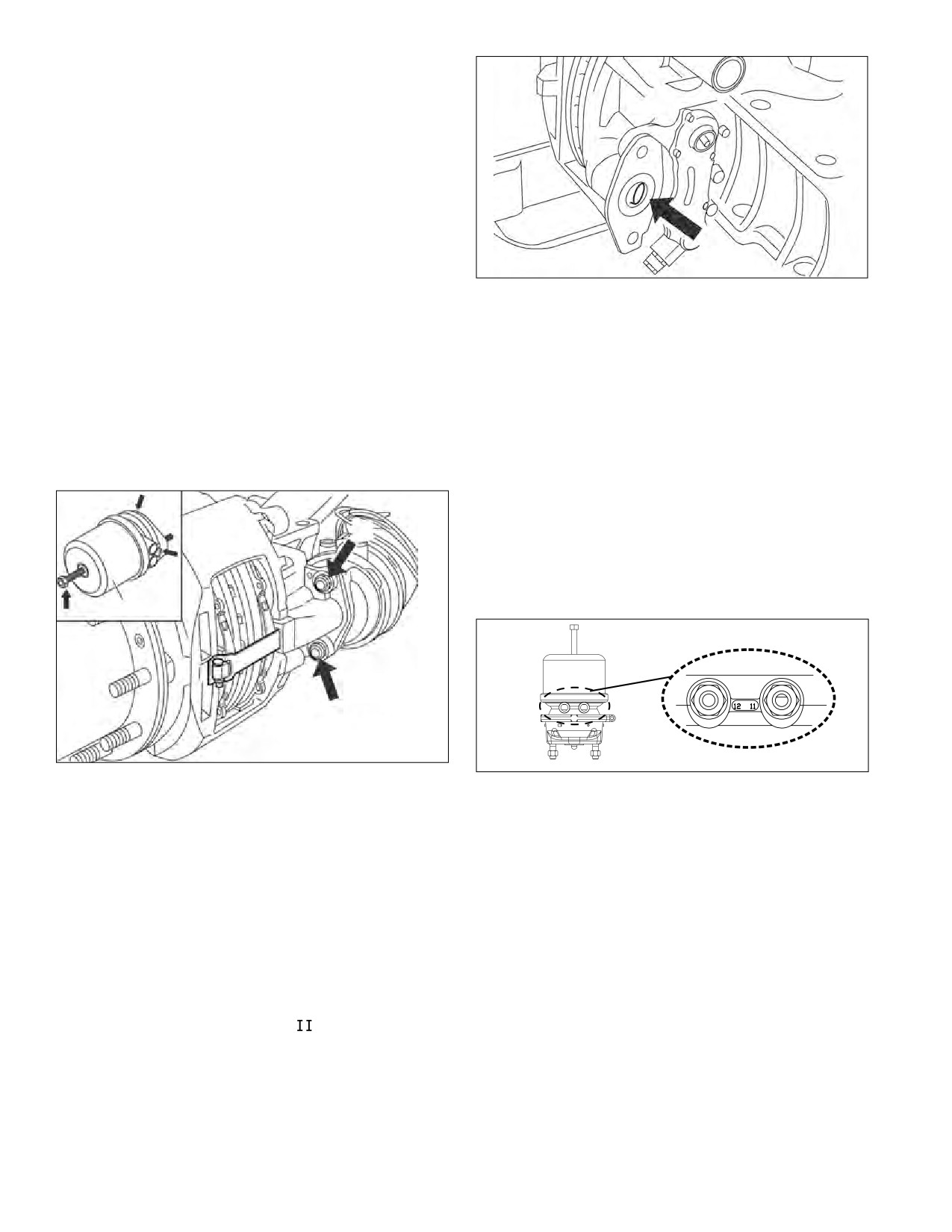
5.4
Spring or Service Brake
5.4.1
CAUTION: Follow all safe maintenance
practices, including those listed on page two of
this document. Park the vehicle (by other means
than the foundation brakes) on level ground and
chock the wheels.
5.4.2
Use the spring brake manufacturer’s recom-
mended safety practices in all cases.
Some spring brake and vehicle manufacturers
C
permit caging the spring brake while the spring
brake is engaged.
Figure 44 - spring brake installation
The following instructions are for Bendix®
CAUTION: Do not use brake chambers with seals that
brand piston-style actuators.
have a thickness less than 0.12 in. (3 mm). Use only
5.4.3
With the vehicle on a level surface and the wheels
actuators which are recommended by the vehicle
properly chocked, apply air to release the spring
manufacturer.
brakes (parking brakes) by using the dash-mounted
5.4.7
Install the brake chamber using new self-locking
air control valve. Back out the release bolt (Figure
nuts (EN ISO 10513). Alternately tighten both the
43, arrow “D”), using a maximum torque of 26 ft. lbs.
nuts step by step up to a final torque of 133 ± 7 ft. lbs
(35 N·m) to cage the air released spring force on
(180 ± 10 N·m). Bendix strongly recommends
the push rod.
that new nuts be used.
A
5.4.8
Re-connect the air hose(s) and be sure that each
hose is not twisted or in contact with moving vehicle
B
components. The air hose routing must allow for full
A
caliper travel. Note that for spring brake service
chambers the ports are indicated by: “11” Service
D
18/1
Brake Port and “12” Spring Brake Port
B
Figure 43 - Actuator spring caging and removal
Figure 45 - Port designations
5.4.4
Exhaust the air from the brake chambers by using
Note: Where a new spring brake chamber is being
the dash-mounted air control valve. With all air
installed, note that in some cases drain plugs are installed
pressure drained from the system, disconnect the
(See Figure 43, arrows marked “A”). Where drain plugs
air hoses from the brake chamber. While supporting
are present, after installation, remove whichever plug is
the brake chamber in position, remove and discard
at the lowest position. The selected drain hole must be
the brake chamber mounting nuts (Figure 45,
aligned downwards (or within ±30°) when installed on the
arrows marked “B”). Remove the brake chamber.
vehicle. In the case of spring brake chambers, install the
pads before uncaging the spring.
5.4.5
Re-installation. Before installing the brake chamber,
the actuator flange (See Figure 46, arrow “C”) must be
5.4.9
Before returning vehicle to service, with the system
cleaned and inspected. Consult the vehicle manual.
pressurized, using a soap solution, check for air
The spherical cup in the lever (19) must be greased
leakage. Minimal leakage in the area around the
with white grease (Part No.
14525 or K021964).
diaphragm is permitted (100 SCCM), and a one-inch
Add grease to the rubber gasket on the chamber.
bubble in one minute at the hose fitting is acceptable.
If abnormal leakage is detected, the diaphragm must
CAUTION: Do not use grease containing molybdenum
be replaced, or fitting adjusted, respectively.
disulfate.
5.4.6 The seal, as well as the push rod area, must be
clean and dry.
24
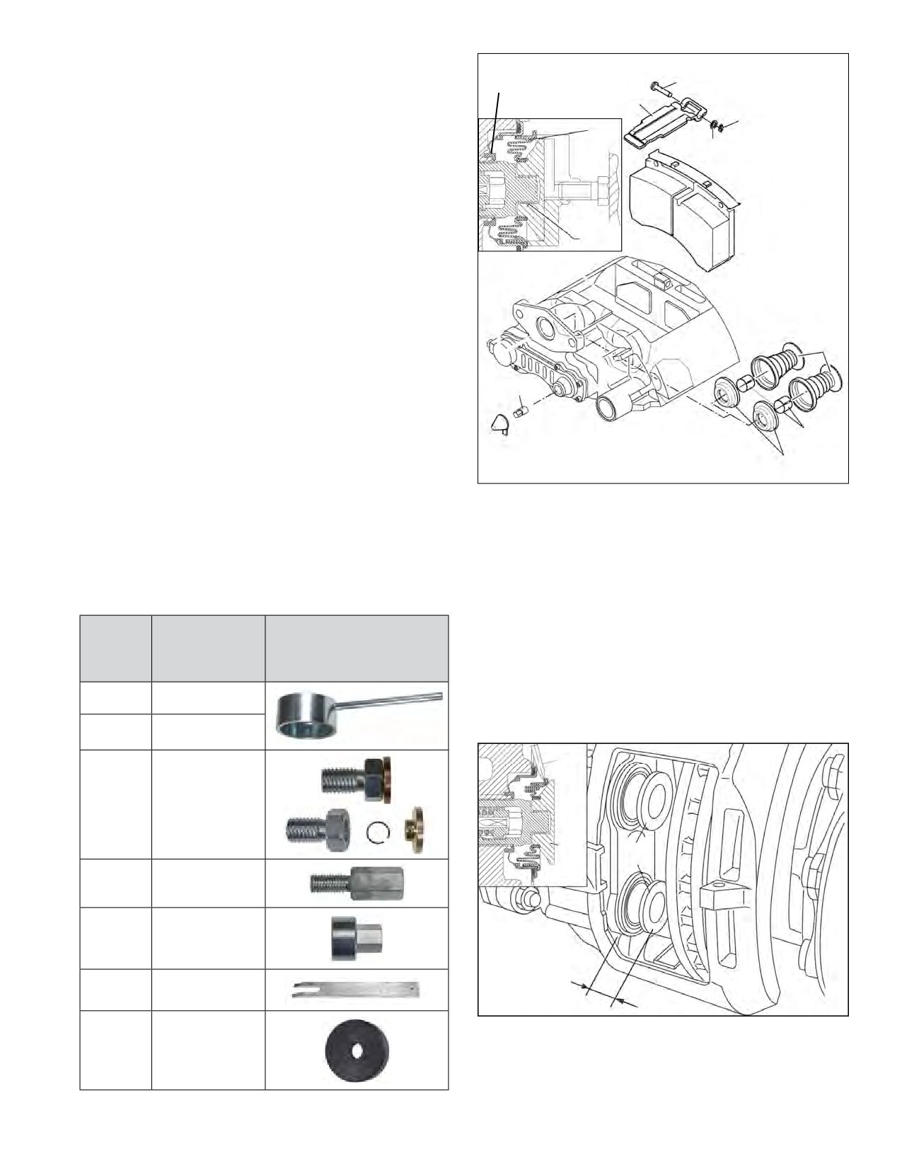
5.5
Tappet & boot Assemblies, and
22
44 Pad Retainer Pin
11
Inner Seal
tappet inner seal Replacement
Pad Retainer
26
5.5.1
CAUTION: Follow all safe maintenance
Spring Clip
13 Tappet
practices, including those listed on page two of
and
45
this document. Park the vehicle (by other means
Boot Assy
Washer
than the foundation brakes) on level ground and
chock the wheels.
In some cases, the technician will need to remove the caliper
12
161
Pad
carrier assembly from the vehicle. (See Section 5.3.) Note
Tappet
Assembly
Bushing
that new bolts (available from the vehicle manufacturer)
will be needed for re-installation.
Important: If the vehicle is equipped with spring brakes,
13
cage the spring brakes on all axles requiring work.
Tappet
Consult the vehicle manufacturer’s instructions as
and Boot
Assembly
necessary. This procedure may be carried out with
the air disc brake installed on, or removed from, the
61
vehicle. In cases where the caliper/carrier assembly
Shear
is removed from the vehicle, NEW fasteners must be
Adapter
used and properly torqued during re-installation. Use
161
only fasteners approved by the vehicle manufacturer.
Tappet
6
Adjuster Cap
Bushing
Note: This maintenance procedure uses specialized
22 Inner Seal
tools. The full Bendix air disc brake tool kit (K029164),
Figure 46 - ADB Exploded and section views
or Ken-Tool kit (80000), includes the complete set of
tools required for all permitted maintenance procedures.
5.5.2
Pad Removal: follow Sections 5.2.1-5.2.11 for
Alternately, for locations where only the tappet and boot
removal of the brake pads.
replacement procedures will be performed, the smaller
5.5.3
Inspect the Brake Rotor (See Section 4.4).
Bendix tool kit (K028829), or Ken-Tool kit (80001) will
Tappet and Boot Assembly (13) Removal
suffice. The DVD (BW7356) shows this procedure.
CAUTION: Never extend the tappet more than
Bendix
1.75 in. (44.5 mm). See Figure 47. Over-extending the
Number/
Description
Typical Tool View
tappet will result in the tappet losing engagement with
Ken-Tool
Number
the threads of the synchronizing mechanism. Since
the mechanism can only be set at the manufacturing
T1 / KT01
Cup
plant, the caliper/carrier assembly must be replaced
if this happens.
T2 / KT02
Handle for KT01 cup
B
Swivel assembly
(KT03-1 short body
T3 / KT03
+ KT03-2 brass disc
+ KT03-3 retaining
spring)
13
13
T4 / KT04
Long strut
T9 / KT09
Flange
Extend
Less Than
1.75 in.
T15 / KT015
Fork
(44.5 mm)
Figure 47 - permitted tappet extension
T24 / KT024
Black Nylon Disc
5.5.4
See Figure 47. Extend the tappets — less than
1.75 in. (44.5 mm) — by turning the shear adapter
(61) clockwise. A screwdriver (callout “B” in
Table 5 - tappet and boot replacement tools
25
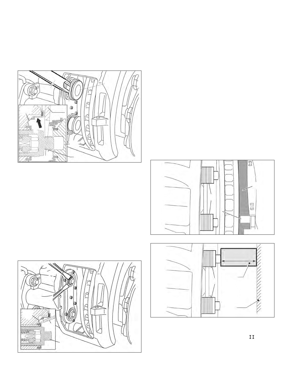
Figure 47 inset) should be used to move the boot
5.5.9
Inspect the inner sealing face for damage. If
and allow the wedge fork (“A” in Figure 48) to be
damage is found that would cause the inner seals
inserted.
not to be able to seal properly, the caliper/carrier
assembly must be replaced. Clean the area around
CAUTION: Do not insert the screw driver more
the inner seal.
than ¼ inch. Take care not to damage the
inner sealing face (see arrow “X” in Figure 48).
5.5.10
Inspect the threaded tubes (16). See Figures 50
Gouges or grooves will prevent a good seal and
and 51. Extend the tubes, but by less than 1.75 in.
will require that the caliper be replaced.
(44.5 mm), by turning the shear adapter (61)
clockwise. Inspect the threads for rust, corrosion, or
damage etc. If there is evidence of damage to the
13
threads; significant rust; or corrosion, the caliper/
T15
carrier assembly must be replaced.
If the technician is working with the caliper on the
vehicle, the technician may place a new brake pad
22
A
(12) into the outboard gap to help avoid the loss
of thread engagement of the threaded tubes. See
Figure 50.
X
If the work is being carried out at a workbench, the
technician may insert a 2.76 in. (70 mm) spacer
13
(See callout “E” in Figure 51) into the caliper (1) to
help avoid the loss of thread engagement.
161
Figure 48 - wedge tool use
5.5.5
The tappet and boot assemblies (13) can then be
removed from the threaded tubes (16) by using the
wedge fork (T15). Be sure to orient the wedge tool
12
with the tapered side towards the tappet.
16
5.5.6
Remove the old tappet bushings (161).
5.5.7
Retract the threaded tubes by turning the shear
adapter (61) counter-clockwise.
46
5.5.8
See Figure 49. Carefully remove the inner seal
using one or two flat-blade screwdrivers as shown.
Caution: Do not insert the screwdrivers so far that
Figure 50 - Use of a new brake pad as a spacer
they come into contact with the threaded tubes.
Damage to the threaded tubes would require that
2.76 in.
the brake be replaced.
(70 mm)
E
16
1
22
Figure 51 - Use of a spacer (off-vehicle inspection)
A
5.5.11 For threads that are in good condition, grease the
threads with white grease (Part No.
14525 or
16
K021964). Before installing the replacement inner
seals (22), retract the threaded tubes by turning the
shear adapter (61) counter-clockwise.
Figure 49 - inner seal removal
26
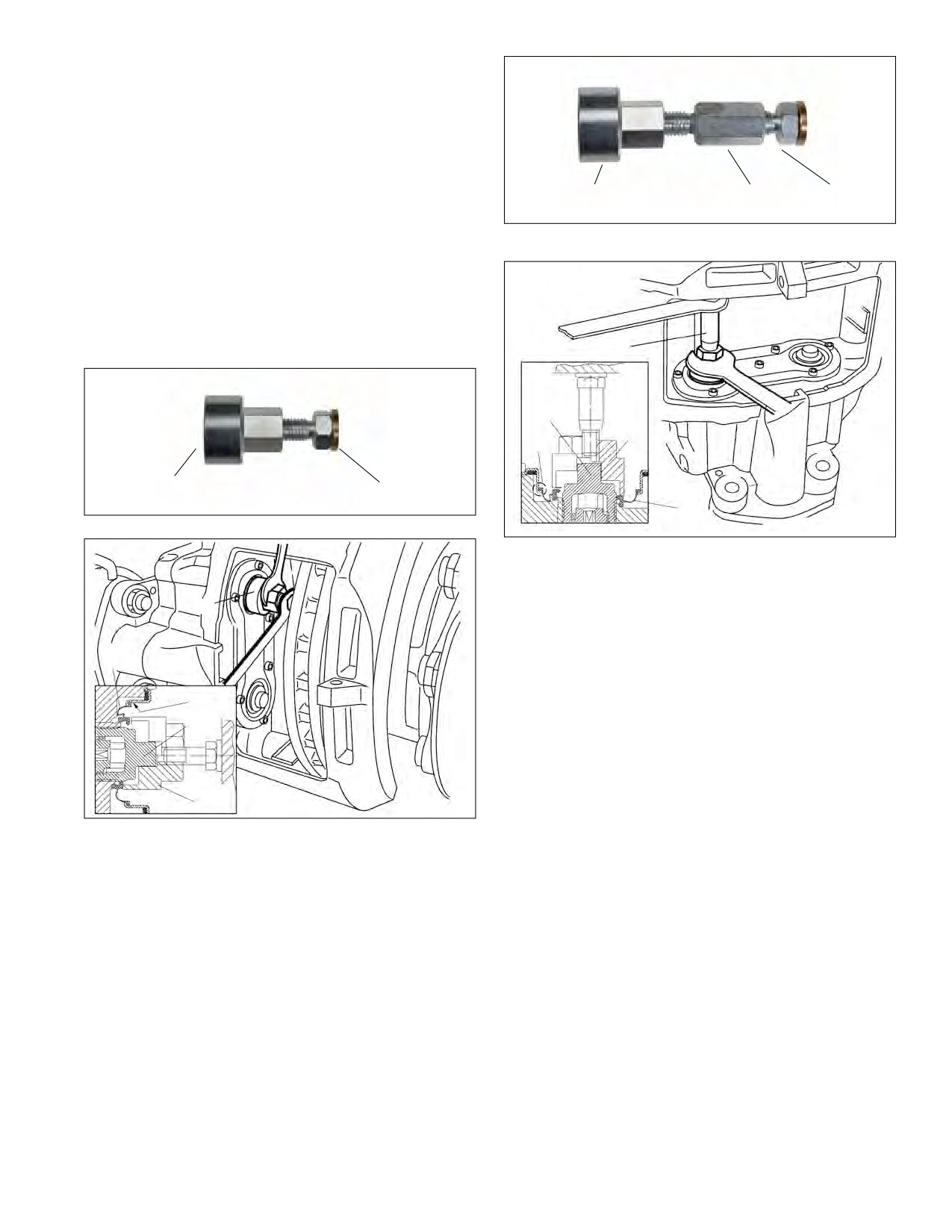
Note: If the shear adapter fails while you are retracting
the threaded tubes, you may try again with another
(new) shear adapter. If this also fails, this indicates
that the adjuster mechanism is damaged and the
caliper must be replaced.
To install inner seals where the caliper is on the vehicle:
5.5.12 Position the replacement inner seal (22) over the
T9 / KT09
T4 / KT04
T3 / KT03
threaded tube (16). See Figures 52 and 53 for the
tools and installation arrangement used. Position
Figure 54 - On-vehicle inner seal installation tool
(L2)
the L1 (T3 + T9) with the short spacer (T3) in
position as shown in Figure 53. Guide the tool
over the end of the threaded tube (16). Install the
new inner seal (22) into position by rotating the
adjuster nut on the T3 portion of the tool, using an
L2
open-ended wrench.
16
L2
X
T9 / KT09
T3 / KT03
22
Figure 52 - On-vehicle inner seal tool (L1)
Figure 55 - Off-vehicle Inner seal installation
CAUTION: To confirm that the inner seal has been
correctly installed, begin to extend the threaded tubes
L1
(16) by turning the shear adapter clockwise by 4-5
turns. Watch as the threaded tube extends. Inner seals
that are installed correctly will not rotate as the
22
threaded tube extends.
X
5.5.14 Note: Inspect the tappet/boot kit to determine if the
16
tappets supplied are already pre-greased (a plastic
cover should be present — be sure to remove the
cover when installing the tappet). Only in the case
of kits that are not pre-greased will the installer
need to apply grease to the tappets. In all cases,
T9
the threaded portion of the tubes will need to be
Figure 53 - On-vehicle inner seal installation
greased. Retract the threaded tubes.
To install inner seals where the caliper has been
5.5.15 Install the new tappet bushing (161) onto the center
removed from the vehicle:
post of each threaded tube (16) by hand. By hand,
5.5.13 Position the replacement inner seal (22) over the
ease the tappet bushings onto the center post of
threaded tube (16). See Figures 54 and 55 for
the threaded tubes and they will snap into position.
the tools and installation arrangement used. The
5.5.16 The sealing seat in the caliper for tappet and boot
threaded tubes need to be retracted to allow the
assemblies (13) must be clean and free of grease.
tool to be inserted. Use the combination tool L2
Wipe the opening with a clean shop rag. Place a
(T4 + T3 + T9) with the long spacer (T4) as shown
tappet and boot assembly (13) in position over the
in Figure 55. Since the installation tool is guided by
center post and tappet bushing.
the center post of the threaded tube, advance the
tube a small amount to align the tool and the center
To install tappet and boot assemblies where the caliper
post. Install the new inner seal (22) into position
is on the vehicle:
by rotating the adjuster nut on the T4 portion of the
5.5.17 See Figures 56, 57 and 58. Use tool B1, comprising
tool using an open-ended wrench.
tools T1, T2, and T3 to press the boot into position.
The tool is then reversed, and the nylon disc (T24)
27
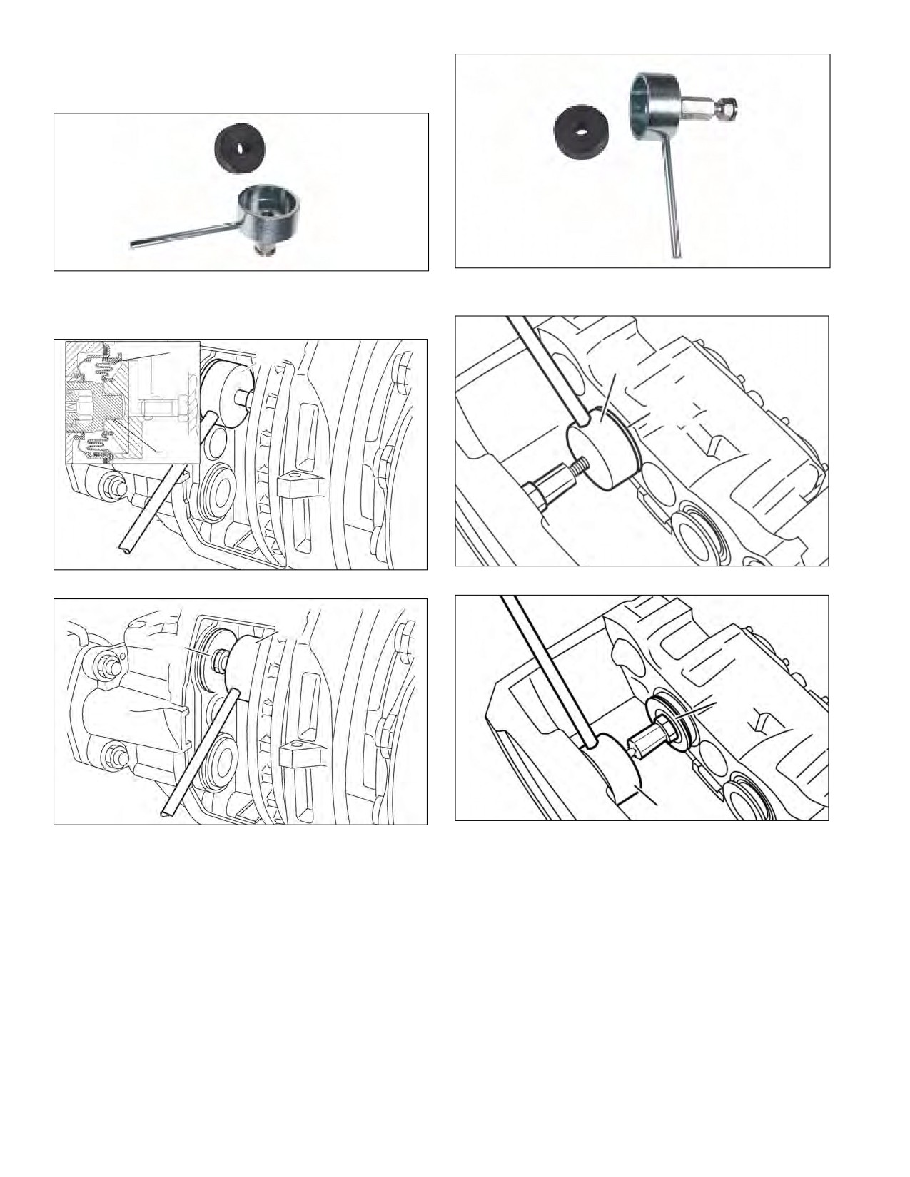
is inserted into the T1 “cup” (combination tool ‘B2’).
Holding the T1 handle, turn the nut on the T3 tool to
fully install the tappet onto the tappet bushing (161).
Figure 56 - On vehicle tappet and boot installation
Figure 59 - Off vehicle tappet boot installation tool
tool (B1 - with T24 installed, B2)
(B3, with T24 installed, B4)
13
B1
B3
13
161
Figure 57 - On vehicle tappet boot installation
Figure 60 - Off vehicle tappet boot installation
B2
13
13
B4
Figure 61 - Off vehicle tappet installation
Figure 58 - On vehicle tappet installation
5.5.19 Check that the tappets are firmly attached to the
To install tappet and boot assemblies where the caliper
bushings by gripping and pulling lightly on them by
is removed from the vehicle:
hand. Confirm that the tappets are able to rotate a
5.5.18 See Figures 59, 60 and 61. Retract the tappets,
small amount on the tappet bushings by grasping
as needed, in order to have room to install the
and turning them by hand. Finally, using a box-end
tappets. Use tool B3, comprising tools T1, T2, and
wrench on the shear adapter, extend the threaded
T3 to press the boot into position. The tool is then
tubes outward, and check that the boots are held
reversed, and the nylon disc (T24) is inserted into
in place. Retract the tappets.
the T1 “cup” (combination tool ‘B4’). Holding the
5.5.20 Re-install the caliper/carrier assembly, if it was
T1 handle, turn the nut on the T3 tool to fully seat
removed from the vehicle (See Section 5.3).
the tappet onto the tappet bushing (161).
5.5.21 Re-install the brake pads (See Section 5.2).
28
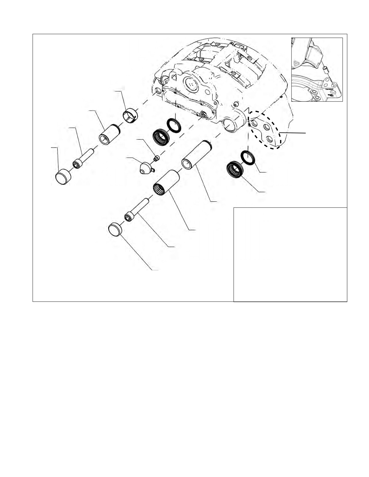
5.6 Guide pin and boot Assemblies
Vertical
Bolt Style
(with
bushing).
Bushing
(6)
Guide Pin
Ring
(4)
(58)
Inner
Horizontal
Boot
Mounting Bolt
Caliper Bolt
(9)
Style Shown:
(39)
Shear
See Inset Above
Adapter
for Vertical
Cap
(61)
Bolt Style (with
(68)
bushing).
Adjuster Cap
(Two alternate
Ring
caps supplied in kit)
(58)
(37)
Inner
Boot
(9)
Guide Pin
(5)
KIT CONTENTS
Item Description
Quantity
Guide Bushing
4 . . Guide Pin (Short)
1
(7)
5 . . Guide Pin (Long)
1
6 . . Bushing
1
7 . . Guide Bushing (Long)
1
Caliper Bolt
9 . . Inner Boot
2
(40)
10
Cap (Small)
1
37
Adjuster Cap (Two versions supplied)
2
39
Caliper Bolt (Short)
1
Cap
40
Caliper Bolt (Long)
1
(10)
58
Ring
2
61
Shear Adapter
1
68
Cap (Large)
1
(White grease is also supplied - not shown)
Figure 62 - Guide pin EXPLODED VIEW
The Bendix DVD (BW7356) shows this procedure.
These procedures are typically carried out with the
caliper/carrier removed from the vehicle (may be
5.6.1
CAUTION: Follow all safe maintenance
carried out with the air disc brake installed). In cases
practices, including those listed on page two of
where the caliper/carrier assembly is removed from
this document. Park the vehicle (by other means
the vehicle, NEW fasteners must be used and properly
than the foundation brakes) on level ground and
torqued during re-installation. Use only fasteners
chock the wheels.
approved by the vehicle manufacturer.
Important: If the vehicle is equipped with spring brakes,
Note: This maintenance procedure uses specialized
cage the spring brakes on all axles to be worked on.
tools. The full Bendix air disc brake tool kit (K029164),
Consult the vehicle manufacturer’s instructions as
or Ken-Tool kit (80000), includes the tools needed for the
necessary. For Bendix® brand piston-style spring
guide pin and boot installation. See Table 6.
brake chambers, see Section 5.4.
Note that a smaller Bendix tool kit (K029107), or Ken-Tool
kit (80002) may be used where only the guide pins will be
serviced.
29
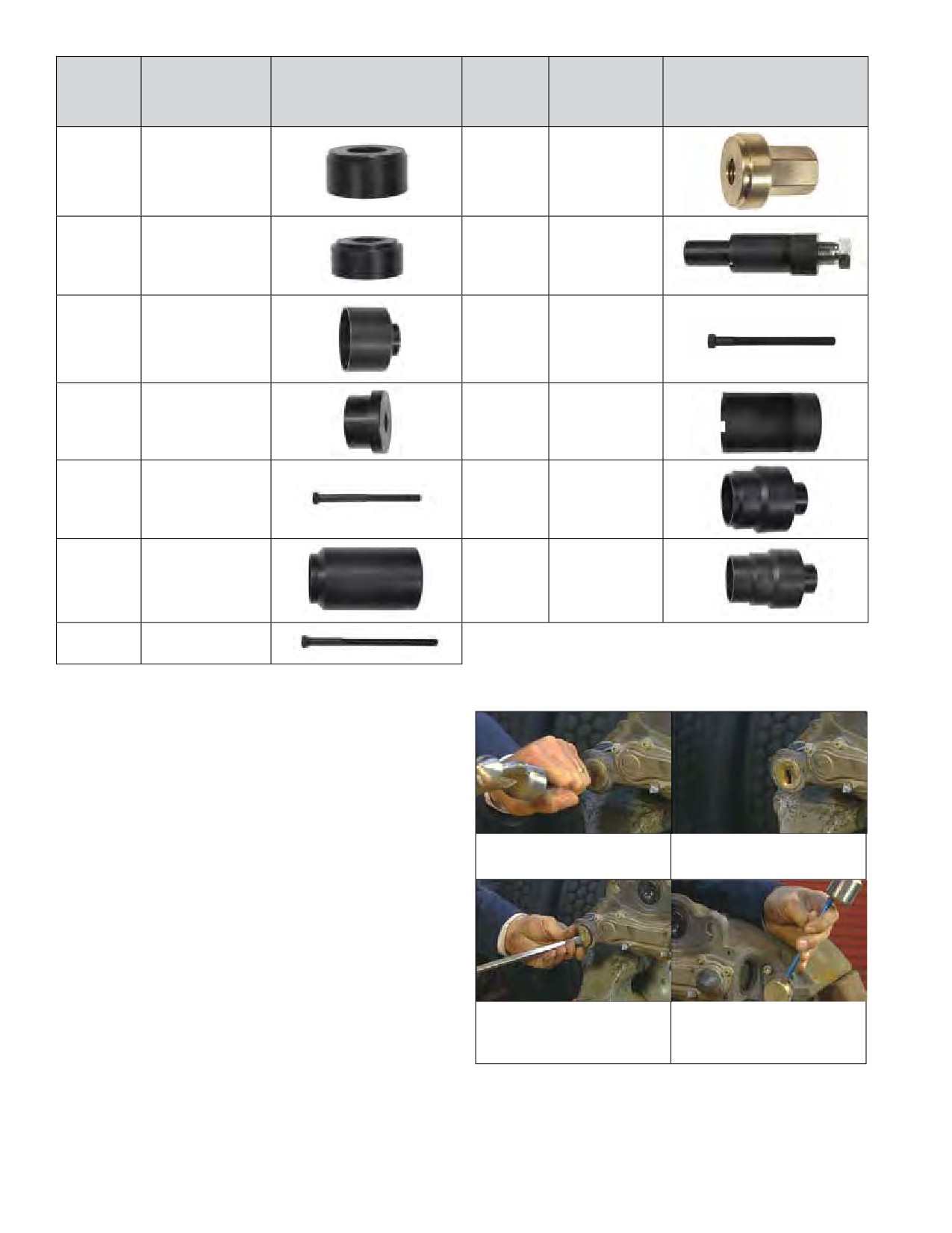
Bendix
Bendix
Number/
Number/
Description
Typical Tool View
Description
Typical Tool View
Ken-Tool
Ken-Tool
Number
Number
T05 / KT05
1-3/8 in. diameter disc
T14 / KT14
Brass nut
T06 / KT06
1-1/2 in. diameter disc
T16 / KT16
Dimpling tool
T07 / KT07
2 in. diameter sleeve
T20 / KT20
8 in. bolt
T08 / KT08
2-1/8 in. diameter disc
T21 / KT21
Half sleeve
T10 / KT10
8 in. bolt
T26 / KT26
Cap installation tool
T12 / KT12
3-7/8 in. long sleeve
T27 / KT27
Cap installation tool
Table 6 - Bendix® ADb22X™ air disc brake guide pin
T13 / KT13
10 in. bolt
and seals replacement tools. (a washer is also
included)
5.6.2
Remove the wheel. Refer to the vehicle manufac-
turer’s recommendations.
5.6.3
Remove the brake pads. See Section 5.2.
5.6.4
In most cases, the actuator should be removed. See
Section 5.4. In the case of spring brake actuators,
they should be caged before removing the brake
assembly.
Figure 63 - Punch guide
Figure 64 - guide pin cap
pin cap (10)
(10) hole
5.6.5
In nearly all cases, the air disc brake caliper/carrier
will need to be removed from the vehicle in order to
complete this procedure. See Section 5.3.
5.6.6
Place the brake on a workbench and, using a vice,
secure it by the carrier.
5.6.7
Use a small chisel or similar tool to punch a hole
close to the center of the guide pin cap (10) of the
Figure 65 - Pry to
Figure 66 - using small
short guide pin, taking care to only insert the chisel
remove guide pin cap (10)
chisel to remove guide
a small amount. Using the hole just made, pry the
pin cap (68)
cap off and discard. See Figures 63-65.
5.6.8
Remove the other cap (68) that covers the long
guide pin, by using a small chisel and hammer to
apply light blows to the cap, with the chisel aimed
away from the casting. See Figure 66. Discard
both caps.
30
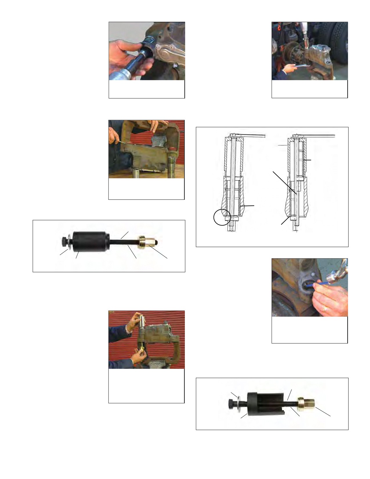
5.6.9
Using a 14 mm hex
5.6.14 Turning the bolt at
bit socket, remove
the top, draw the
and discard the two
brass nut up, bring
caliper bolts (39) and
the brass bushing
(40). See Figure 67.
up and out of the
By hand, retract both
channel. Discard the
guide pins slightly
bushing.
and then remove
the caliper from the
Figure 67 - remove the
Figure 71 - remove the
carrier.
caliper bolts
long guide pin
The guide pins are now only held by the retaining
Caution: Keep the removal tool exactly aligned with the
rings (58).
guide pin channel to permit the bushing to be removed.
See Figure 72.
5.6.10
Remove the boot
retaining rings (58)
and the guide pins
T12 / KT12
(39) and (40). Use
a screwdriver to pry
Bushing (10)
out the inner boots
Removed
(9). See Figure 68.
T13 /
KT13
Discard the removed
items.
Figure 68 - remove the
retaining rings, guide
pins, and boots
5.6.11
Clean the caliper upper and lower surfaces around
Bushing
(10)
the bushings.
Installed
T14 / KT14
Grease the bolt prior to each use
Above: Incorrect
Above: Correct
Alignment
Alignment
Figure 72 - Keep the correct alignment
Washer
T12 / KT12
T13 / KT13
T14 / KT14
5.6.15 Prepare to remove
the short guide pin
Figure 69 - brass Bushing removal tool
bushing by locating
the bushing (6) tab,
5.6.12 Prepare to remove the brass bushing used in the
long guide pin side. Assemble the long bolt (T13),
and using a small
chisel (narrower than
washer, and sleeve (T12) as in Figures 69 and 70.
the tab) or similar
5.6.13 Apply grease to the
tool, remove the tab
bolt and
— after
as shown in Figure
Figure 73 - remove the
tab that holds the
inserting through the
73, by striking low on
bushing in position
guide pin channel —
the base of the tab.
engage the brass
Remove the tab with a magnet and use a clean
nut (T14). Always
shop cloth to remove any excess debris. Note
double-check that
that in some cases, the tab may be in the opposite
the brass nut is
(outer) slot in the bore.
correctly in place in
Figure 70 - install the
removal tool
the bushing before
Grease the bolt prior to each use
beginning to extract
Washer
the bushing.
T20 / KT20
T14 / KT14
T21 / KT21
Figure 74 - short guide pin removal tool
31
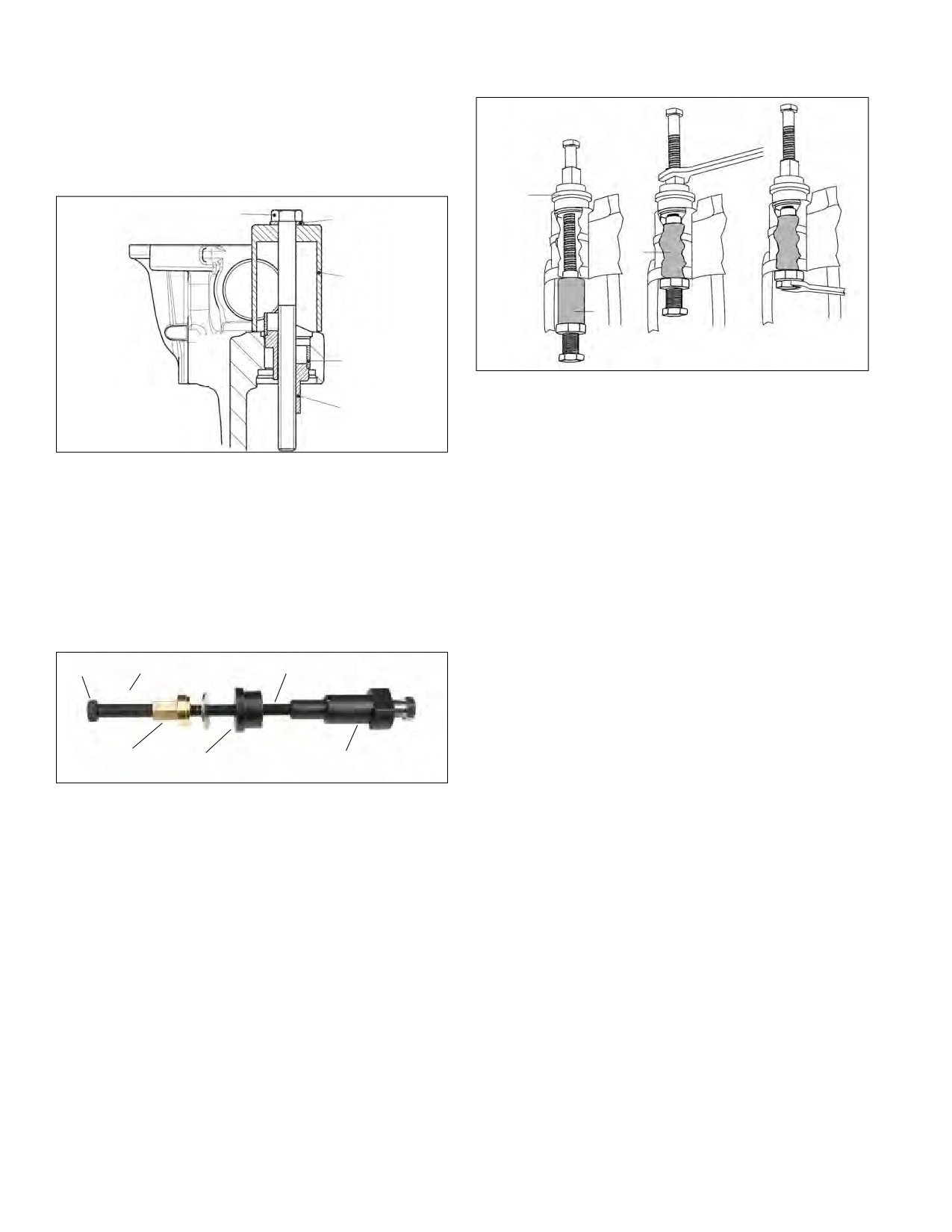
5.6.16 Use the tool combination shown in Figures 74 and
5.6.20 Place a new brass guide bushing (7) on the dimpling
75 (comprising T14, T20, T21, and a washer) to
tool (T16) and insert it into the caliper bore.
remove the bushing (6). Screw nut (T14) onto the
assembly by hand, then tighten the bolt (T20) using
a box end wrench to draw out the bushing. Discard
the removed bushing, and verify that the bore is
clean by wiping with a shop cloth.
T14/
KT14
T20
Washer
7
T21
7
View
View
View
“A”
“C”
“B”
6
Figure 77 - View “a” and “b”: draw the brass bushing
into position. View “C”: lock the bushing into
T14
position
5.6.21
Check that the flange (T08) is in an upright position
at the top of the caliper recess as you draw the brass
Figure 75 - sectional view: short guide pin bushing
removal
bushing (7) up, by turning the brass nut (T14), until
the dimpling tool bottoms on the caliper. When it
Installation of the Fixed Guide Pin Brass
reaches the correct position, the brass bushing
Bushing
extends out of the guide pin channel 0.039 in.
(1 mm.).
5.6.17 Clean the caliper upper and lower surfaces around
the bushings.
5.6.22
With the dimpling tool (T16) in position, tighten the
5.6.18 Clamp the carrier in a vise so that the guide channel
screw in its base until it contacts the dimpling screw
housing. The movement of this screw forces three
is vertically oriented.
points outwards, leaving indentations in the brass
Grease the bolt prior to each use
bushing. See Figure 77, view “C”.
T13 / KT13
Washer
5.6.23
Unscrew the dimpling screw out approximately 0.75
inches (20 mm.). Loosen the brass nut (T14) and
rotate the dimpling tool (T16) 60 degrees. Repeat
the dimpling process by tightening the brass nut
T14 / KT14
T08 / KT08
T16 / KT16
(T14) and then tighten the dimpling screw until it
contacts the dimpling screw housing. Back out the
Figure 76 - Long guide pin bushing installation and
dimpling tool
dimpling screw approximately 0.75 inches (20 mm.).
The brass bushing (7) is now held in position by the
5.6.19 Place the washer and thread the brass nut (T14) on
six dimples made by the tool.
to the bolt (T13) followed by the flange (T08). See
Figure 76.
5.6.24
Remove the installation tools and check the brass
bushing (7), removing any burrs, being careful not
to leave any metal filings in the bushing. Coat the
inside of the bushing with the white grease included
in the kit.
Installation of the Floating Guide Pin Bushing
5.6.25 To install the bushing (6) into the short guide pin
side, first inspect the bore for corrosion, damage
etc. Clean as necessary.
32
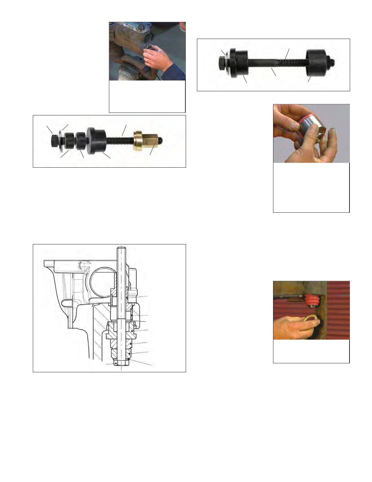
5.6.26 Place the new bush-
surface of the caliper is damaged, replace the
ing (6) in position so
caliper.
that when drawn
Washer
Grease the bolt prior to each use
into position, the
tab will align with
the slot in the cast-
ing. With the tab
aligned, place tool
T10 / KT10
(T14) over the bush-
T08 / KT08
T07 / KT07
Figure 78 - Position the
ing and tap lightly. To
new bushing
Figure 81 - short guide pin boot installation tool
position the bushing,
see Figure 78.
5.6.31
See Figure 82. Place
a boot into the in-
T20 / KT20
Washer
Grease the bolt prior to each use
stallation tool (T7),
making sure that
the inner bellows
are arranged close
to the side walls of
T14 / KT14
T05 / KT05
T06 / KT06
T08 / KT08
the tool and will not
be damaged dur-
Figure 82 - Position
Figure 79 - short guide pin bushing installation tool
the new boot in the
ing installation. Also
installation tool (T7)
5.6.27
Use the tool combination shown in Figure 79 to
check that the outer
draw the bushing (6) into the caliper. See also
edge of the boot
Figure 80, to see the orientation (with tool T14 at
rests on the front
the top). Hand tighten the nut (T14) into position.
edge of the tool.
Then tighten the bolt (T20) using a box end wrench
or socket to draw the bushing (6) into the caliper
until the bushing (6) contacts the machined step in
5.6.32
Using 70 in. lbs. (8 N·m) of torque maximum, tighten
the bore. Remove the tool.
bolt (T10) to install the inner boot.
5.6.33
Repeat the installation procedure for the second
inner boot.
5.6.34
Check that the boots are held securely in place and
that no damage occurred during installation.
5.6.35
See Figure 83. To
install the guide
T14
pins, first lubricate
both guide pins with
6
the white grease
Bushing Stop
supplied. Insert the
T08
guide pins into their
respective bores
T06
with the grooved end
Figure 83 - Place the
T05
retaining ring onto the
towards the bellows.
groove in the guide pin
T20
Washer
Fit the lip in the end of the inner boots (8) into the
groove of the guide pins. Push on each ring (7)
Figure 80 - guide pin bushing installation
ensuring that the boot (9) is engaged onto the end
5.6.28 Using a punch, bend the tab into the groove by
of the guide pins (5 or 6).
aligning the punch with the upper part of the tab
and tapping the punch with a hammer.
5.6.36
With the caliper resting on a bench, slide the carrier
into place with a slight rocking motion, taking care
5.6.29 Coat the inside of the bushing (6) with a light coat
that as you do so, the inner boots and guide pins
of the white grease included in the kit.
are seated in their proper place on the carrier.
5.6.30 Install the two identical inner boots (9) by first
5.6.37
Identify the two caliper bolts (39) and (40). With the
cleaning the area where the inner boots will be
shorter bolt placed in the floating pin bushing (4), and
installed and inspect for corrosion. If the sealing
the longer bolt placed in the fixed pin bushing (5),
33
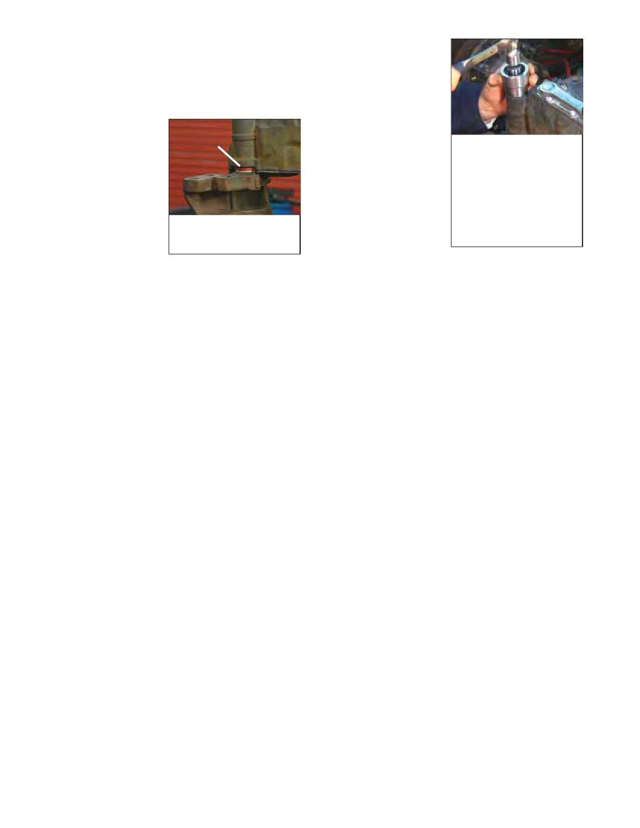
begin to tighten the bolts. With the caliper/carrier
5.6.40
Select one cap to
in a vice, continue installing the bolts to a torque of
install. Using the
133 ft. lbs. (180 N·m). Finally, tighten each bolt an
correct press-in
additional 90º (ninety degrees).
tool — the smaller
cap (10) installs in the
Installation of the Guide Pin Caps
long guide pin side
using tool (T26), and
5.6.38
See Figure 84. Place
BOOT
the larger cap (68)
the caliper/carrier as-
COMPRESSED
installs in the short
Figure 85 - bootS must
sembly on a bench
BE COMPRESSED FULLY
guide pin side using
so that the inner
DURING CAP installation
tool (T27) — place
boots are fully com-
the cap in position,
pressed, check that
using the machined
the bores are clean
channel in the caliper
and dry (e.g. free
Figure 84 - bootS must
to assist in centering
from lubrication).
BE COMPRESSED FULLY
the tool.
DURING CAP installation
Use a hammer to tap the cap into position. See
Note: It is important that the inner boots are fully
Figure 85. Note that the tool needs to remain
compressed during this procedure to ensure that
perpendicular to the channel to prevent damage
the least amount of air is retained within the guide
during installation. Note that, after installation, the
pin channel. If too much air is trapped, the bellows
smaller cap (10) extends 0.08 in. (2 mm.), and the
can potentially be damaged during the operation of
larger cap (68) extends 0.61 in. (15.5 mm.).
the brake. It is also important that the technician
double-check that the retaining rings remain in their
Repeat for the second cap.
correct position during this procedure.
5.6.41
Check that the guide pins move freely when the
carrier is moved laterally, and that air is not trapped
5.6.39
Clean the two caps, and check that the caliper
surfaces where the caps will be installed are clean
within the inner boots, and that the boots (9) and
ring (58) are in the proper position before continuing
and have no signs of damage.
with the installation.
5.6.42
Install the caliper/carrier (See Section 5.3).
5.6.43
Install the brake chamber (See Section 5.4).
5.6.44
Install the brake pads (See Section 5.2).
34
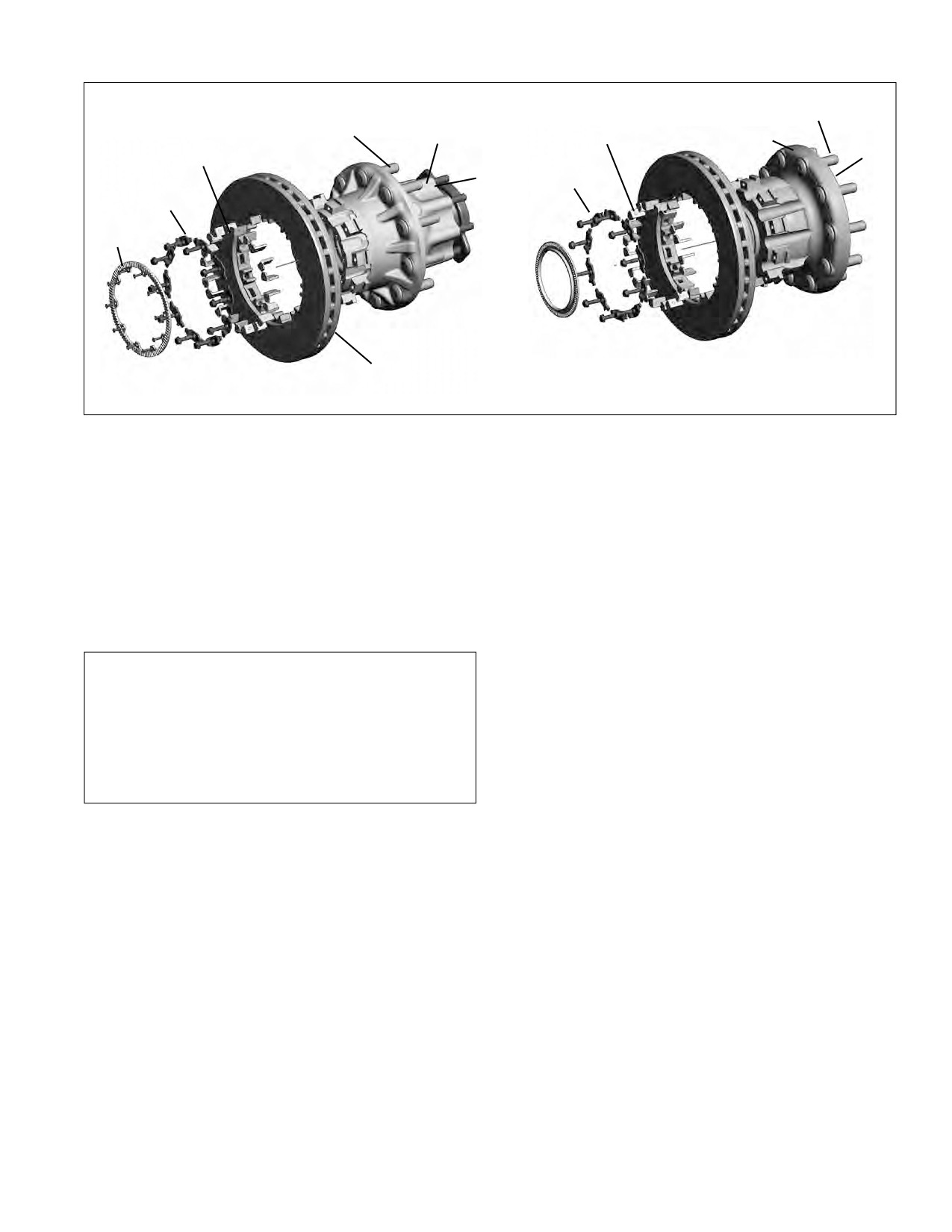
5.7 Bendix® splined disc® Hub rotor
DRIVE HUB
STEER HUB
Wheel Studs
Wheel Studs
Intermediate Elements
Hub
(Spacers)
Hub
Intermediate Elements
ID Label
Spring Elements
(Spacers)
(Retention
Spring Elements
ID Label
Brackets)
(Retention
Brackets)
ABS Tone
Wheel
& Fasteners
ABS Tone Wheel
(press on)
Splined Disc Rotor
Above: Splined Disc Rotor on Aluminum Drive Hub
Above: Splined Disc Rotor on Aluminum Steer Hub
Figure 86 - Splined disc rotor examples - EXPLODED Views
Bendix® Splined Disc® Hub Rotors are designed to assist
Bendix Air Disc Brakes are precision-engineered braking
vehicle maintenance by typically allowing the rotor to be
mechanisms. The “friction couple” braking characteristics
serviced without requiring the entire hub/rotor assembly
have been carefully optimized and the rotor design and
be replaced.
materials have been matched with special formulation
brake pads for optimal performance, therefore use only
Periodic inspection of the Splined Disc attachment
genuine Bendix® brand parts and brake pads.
hardware is recommended to ensure optimum braking
performance. Bendix recommends verifying the torque on
Rotor Replacement
the spring element fasteners whenever a brake inspection
5.7.1
Before removing the brake pads it is strongly
is performed.
recommended that the air disc brake adjuster
NOTE: Anytime that the entire hub/rotor assembly
mechanism be checked for correct operation (See
is removed, Bendix recommends that the wheel seal
Section 4.1). When replacing brake pads, Bendix
also be replaced at the same time, using a high-
strongly recommends that the pads be replaced as
temperature seal. Follow the wheel seal and/or
an axle set.
vehicle manufacturer's guidelines for full installation
5.7.2
Refer to the vehicle manufacturer’s recommendations
instructions. Adjust the bearings and refill bearing
and release (or cage) spring brakes and remove the
oil to vehicle manufacturer's specifications.
wheel.
When replacing a Splined Disc Rotor, Bendix strongly
5.7.3
Remove the pads (See Section 5.2).
recommends that the brake pads be replaced (as an
5.7.4
Remove the air disc brake (See Section 5.3).
axle set.) Contact 1-800-AIR-BRAKE for appropriate
5.7.5
Remove the hub rotor assembly.
brake pad kit. Rotor replacement necessitates the
removal of the pads.
Note: Follow the vehicle manufacturer's guidelines for
removal of the wheel hub and rotor assembly from the
CAUTION: Follow all safe maintenance practices,
vehicle in lieu of these instructions, where available.
including those listed on page two of this document.
Park the vehicle (by other means than the foundation
Caution: Be sure to secure both the rotor and hub
brakes) on level ground and chock the wheels. Also
before removing the retention clips.
read the vehicle manufacturer's recommendations.
5.7.6
Remove and discard the ten spring elements.
When installing pads, where appropriate, use heavy
duty gloves and always keep fingers away from
5.7.7
On drive axles, the ABS tone ring must also be
potential pinch hazard areas.
removed. (See Figure 86.) Retain for re-installation.
5.7.8
Use suitable hand tools to remove the intermediate
elements (spacers). Remove all the right-hand
intermediate elements (spacers) of each set first
and then the rotor can be turned slightly to release
35
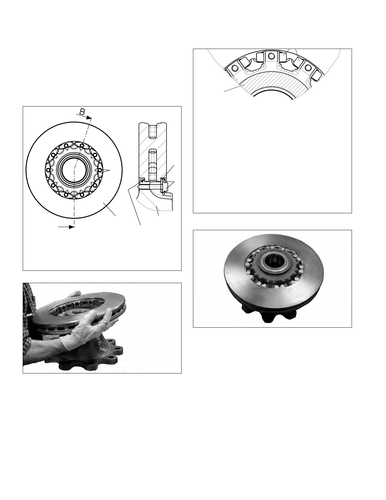
the remaining intermediate elements (spacers).
be corrected with proper installation of new rotor
In all cases, take care not to damage the hub and
retaining hardware.
its teeth. Remove and discard the intermediate
elements (spacers) and retention clips attaching
the rotor. Discard the rotor.
5.7.9
Following industry standards, clean and inspect the
hub before installing the rotor. Look for corrosion
and/or damage to the hub and inspect the wheel
speed tone ring. Where necessary, consult the hub
1
manufacturer's guidelines for more details.
B-B
3
4
4
KEY
1 - Wheel Hub
2 - Splined Disc Rotor
3 - Intermediate Elements (Spacers)
2
1
Figure 89 - installing Intermediate Elements
B
(spacers)
KEY
1 - Wheel Hub
2 - Splined Disc Rotor
3 - Intermediate Element (Spacer)
4 - Spring Element (Fastener), including retention clips
Figure 87 - Rotor with cross-section view
Figure 90 - Intermediate Elements (Spacers) installed
5.7.11 Install the ten new spring elements included in the
kit in an evenly-distributed cross-pattern sequence.
Torque to 22.1 ft. lbs. (30 N·m.)
5.7.12 Where the tone ring was removed during step 5.7.7,
Figure 88 - Rotor installation
re-install the tone ring. Use a professional grade
fastener compound, such as Loctite blue 242, on
ROTOR INSTALLATION
the fasteners. Torque to 19-22 in. lbs. (2.1-2.5 N·m.)
5.7.10 See Figures 87 through 91. Place the rotor into
5.7.13 Re-install the hub rotor assembly using a new
position on the hub. Install the new intermediate
high-temperature wheel seal, following the vehicle
elements (spacers) as shown in Figure 89. With
manufacturer’s instructions.
all the intermediate elements (spacers) correctly
inserted into position, verify that the gap between
the intermediate elements (spacers) and the wheel
hub does not exceed 0.015 in (0.4 mm). If a gap is
found that exceeds this maximum value, verify the
installation of new intermediate elements (spacers).
Replace the wheel hub if the excess gap cannot
36
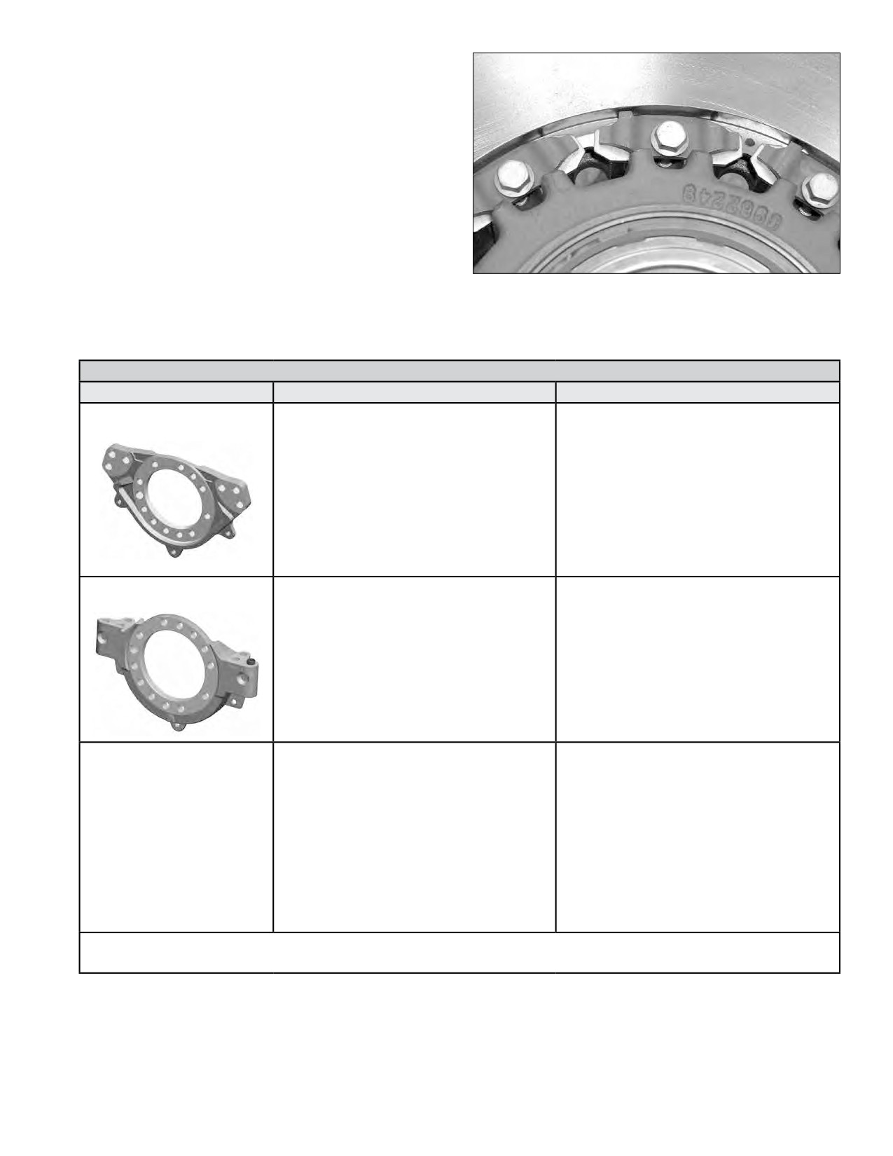
5.7.14 Re-install the air disc brake (See Section 5.3).
Supporting the air disc brake by all necessary
means, attach the brake to the anchor plate
using six bolts and washers as required (Bendix
recommends the original bolts not be re-used).
Torque to vehicle manufacturer's specifications.
If torque values and bolts are not specified by the
vehicle manufacturer, then torque according to the
chart below. Be sure to select bolts with the same
thread pitch, length and grade as originally provided
from vehicle manufacturer.
5.7.15 Reinstall the brake pads (See Section 5.2).
Figure 91 - fasteners installed
Air Disc Brake Attachment Hardware
Torque Plate Manufacturer
Fastener
Torque
Bendix Axial
Carrier Torque Plate
Fastener: M20 x 2.5 x 60 mm Class 10.9
Washer: Requires a THROUGH
Use the manufacturer’s recommendations.
HARDENED 3 mm (minimum thickness) for
If unavailable, use phosphate
each bolt.1 If the vehicle is using a Bendix
and oil finish fastener.
manufactured Axial Anchor Plate, with a
thickness of 1.14 in. (29 mm) where these
Pre-Torque: 20-60 ft-lbf [27-81 N·m]
bolts are assembled, then a bolt with an
Final Torque: 350-400 ft-lbf [475-542 N·m]
overall length of 2.36 in. (60 mm) will meet
these requirements
Bendix Vertical
Carrier Torque Plate
Use the manufacturer’s recommendations.
Fastener: M16 x 2.0 x 110 mm, Class 10.9
If unavailable, use plain and oil finish fastener.
Washer: None required.
Torque: 200-220 ft-lbf [271-298 N·m]
Fastener: M20 x 2.5 x L Class 10.9
Use the manufacturer’s recommendations.
Length determination:
If unavailable, use phosphate
L = Torque Plate (TP) thickness + Carrier
and oil finish fastener:
engagement + Washer thickness
Trailer Torque Plate
Pre-Torque: 20-60 ft-lbf [27-81 N·m]
Lmin = TP thickness + 24 mm + 3 mm
Final Torque: 350-400 ft-lbf [475-542 N·m]
Lmax = TP thickness + 29 mm + 3 mm
Washer: Requires THROUGH HARDENED
3 mm (minimum thickness) for each bolt.1
Footnote 1 CAUTION: The washer outside diameter must be less than 1.5 in (37.5 mm).
Recommended washers conform to DIN125-21-300HV, ISO7089-20-300HV, or ISO7090-20-300HV.
Table 7 - Torque plate fasteners and torque recommendations (see Manufacturer’S recommendations)
37
Service Data Index
Section One: Air Disc Brake Overview
1
Safe Maintenance Practices
2
Section Two: Preventive Maintenance Schedule and Wheel-On Inspections .6
2.0
Preventive Maintenance
6
2.1
Brake Pad And Rotor Inspections
7
2.2
Running Clearance Quick Inspection
8
Section Three: Troubleshooting Procedure Flowchart
9
Section Four: Wheel-Off Maintenance Inspections
10
4.0
Wheel-Off Inspections
10
4.1
Caliper Movement Test
10
4.2
Adjuster Mechanism Inspection
11
4.3
Inspect The Brake Pads
12
4.4
Inspect The Rotor
13
4.5
Guide Pin Bearing Inspection
14
4.6
Tappet And Boot Assembly Inspection
15
Section Five: Maintenance Kits And Procedures
16
5.0
Maintenance Kits
17
5.0.1 General Information About Bendix Air Disc Brake Maintenance
18
5.1
Air Disc Brake Shield Kit
19
5.2
Pad Replacement
20
5.3
Caliper/Carrier/Actuator Assembly
22
5.4
Spring or Service Brake
24
5.5
Tappet & Boot Assemblies, and Tappet Inner Seal Replacement
25
5.6
Guide Pin and Boot Assemblies
29
5.7
Bendix® Splined Disc® Hub Rotor
35
Contacting Bendix
40
38
CONTACTING Bendix
Bendix on-line information is available 24/7/365. It’s your complete Bendix resource.
Bendix Technical Assistance Team
For direct personal technical support, call the Bendix TechTeam at
1-800-AIR-BRAKE (1-800-247-2725).
Representatives are available to assist you Monday through Friday, 8:00 A.M. to 6:00
P.M. EST, or e-mail the Bendix Tech Team at:
techteam@bendix.com.
To better serve you, please collect the following information before you call the
Bendix TechTeam, or include this information in your e-mail:
• Bendix product model number, part number and configuration.
• Vehicle make and model.
• Vehicle configuration. (Number of axles, tire size, etc.)
• System performance symptoms: When do they occur?
• What troubleshooting/measurements have been performed?
• What Bendix service data literature do you have or need?