Champion Bus CHALLENGER. Maintenance Manual
Congratulations on your new Champion Bus, Inc. bus. If this is your first, let me
extend a warm welcome to the Champion Bus family. If you are one of the many
Americans and Canadians for whom Champion Bus ownership has become a tradition,
we believe that your new Champion Bus will surpass your high expectations for a
motor coach. It’s no exaggeration to say that your new Champion Bus represents major
improvements in design and construction since the company began making buses.
Please take a few minutes to acquaint yourself with your new coach. In this manual,
along with the chassis, and other O.E.Ms., you will learn a great deal about your new
vehicle and any options it may have.
If you have additional questions, don’t hesitate to contact your National Bus Sales
Dealer or the Service Department on the following page.
Please count on us to deliver the unparalleled support you should expect as a
Champion Bus, Inc. bus owner.
Sincerely yours,
John Resnik
President, Champion Bus, Inc.
CONTENTS
About this manual…
This Maintenance Manual identifies service related issues for your Champion Bus Challenger.
These issues are the most common general maintence issues.
Information in this manual is listed in sections. These sections include; Chassis, Interior,
Seats, Doors, Windows, and More.
Use the Bookmark Tab to navigate through the manual or you can use the “Find” command
to search for a particular installation or part.
Service Instructions…
All inquiries must include: Customer, the Unit’s Number and Serial Number, Part Number
and description of problem. Address all correspondence to the following addresses of:
Mail:
Champion Bus, Inc.
331 Graham Road
Imlay city MI 48444
Phone:
800-776-1943 ext. 562
Fax:
810-724-6478
Note:
**This manual covers general maintence on the modified portion of the bus. The
chassis section is generic and specific service inquiries are to be directed to the original
manufacturer of the chassis.
**Specifications, descriptions and illustrations in this manual is as accurate as known at the time of publication.**
CONTENTS
INTRODUCTION
GENERAL INFORMATION
SECTION 1
CHASSIS
SECTION 2
FLOORING & INTERIOR
SECTION 3
SEATING
SECTION 4
EXTERIOR
SECTION 5
DOORS
SECTION 6
WINDOWS
SECTION 7
ELECTRICAL & LIGHTING
SECTION 8
HVAC & PLUMBING
SECTION 9
OPTIONAL EQUIPMENT
SECTION 10
BUS MAINTENANCE CHECK LISTS
SECTION 11
INDEX
Section 1 - General Information
GENERAL COACH AMERICA, INC. SERIAL NUMBER
03
CAB AREA
03
VEHICLE’S DASH PANEL
04
CONTROL CONSOLE
04
CAB AREA HEATING & COOLING
04
POWER DISTRIBUTION CENTER
05
HAZARD WARNING LIGHTS
05
TOWING
05
FRONT TOW HOOKUP
06
REAR TOWING HOOKUP
06
EMERGENCY STARTING WITH JUMPER CABLES
07-8
EMERGENCY REFLECTIVE TRIANGLE WARNING KIT
08
RUNNING OUT OF FUEL
09
ROOF ESCAPE HATCH
09
BOLT TORQUE GUIDE
10
SECTION 1
General Information
General Coach America, Inc.
Serial Number
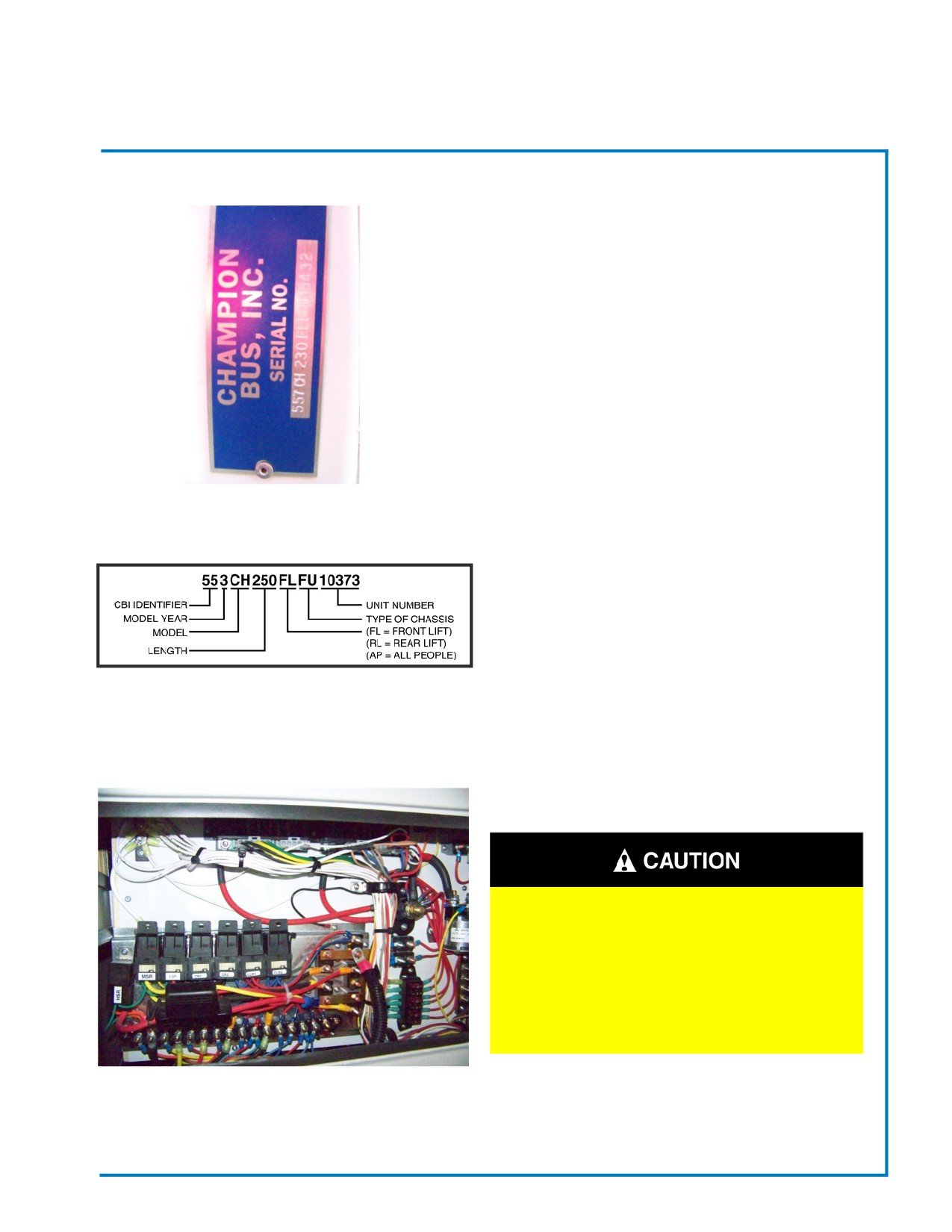
The GCA Serial Number is different from the Vehicle
Identification Number (VIN). The GCA Serial Number
is located on a plate in the engine compartment. It is
used by the manufacturer to identify the bus and it’s
options. When contacting the dealer for service or for
a warranty claim, be sure to provide the serial number
for identification. Refer to Fig. 2 for an example of a
serial number.
Fig. 1-1 Serial Number Plate
CAB AREA
The driver operates the bus from the cab area. To con-
trol the many electrical systems, wiring harnesses are
routed from the power distribution center (as shown in
Fig. 3), behind the cab’s interior trim panels to other
areas throughout the bus.
Fig. 1-2 Example of GCA Serial Number
WIRING HARNESS ARE LOCATED
BEHIND THE CAB’S INTERIOR TRIM
PANELS…NEVER PUNCTURE OR
ATTACH TO TRIM PANELS WITHOUT
FIRST CONSULTING YOUR DEALER.
SEVERE DAMAGE TO THE BUS’S
ELECTRICAL SYSTEM MAY RESULT.
Fig. 1-3 Power Distribution Center
Revised: October 2007
Page 03
Champion Bus, Inc. Maintenance
SECTION 1
General Information
VEHICLE’S DASH PANEL
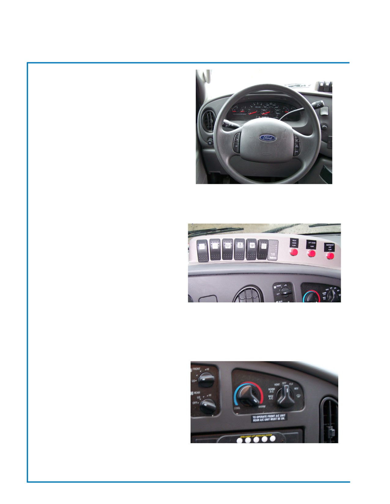
Details on Vehicle Dashboard instrumentation, steer-
ing, or other chassis controls are covered in the Ford
Owner’s manual included with your bus. Please read
the manual to become familiar with the Vehicle’s
Dashboad before operating the bus.
Fig. 1-4 Dash Panel
CONTROL CONSOLE
The Control Console (Fig. 5) allows the driver to
control some of the electrical components of the bus.
It also houses warning lights and buzzers that lets
the driver know if something is ajar, etc. The Control
Console is mounted to the dash board, within easy
reach and clear view of the driver. Controls and dis-
plays vary, depending on how the bus is equipped, but
all controls and switches are clearly labelled for easy
reference.
Fig. 1-5 Dash Mounted Control Console
CAB AREA HEATING & COOLING
Cab Area Heating and Cooling Controls are located
on the dashboard, within easy reach of the driver. Op-
erational and maintenance information on particular
system can be found in the chassis owner’s manual.
Fig. 1-6 Cab Heating & Cooling Controls
Revised: October 2007
Page 04
Champion Bus, Inc. Maintenance
SECTION 1
General Information
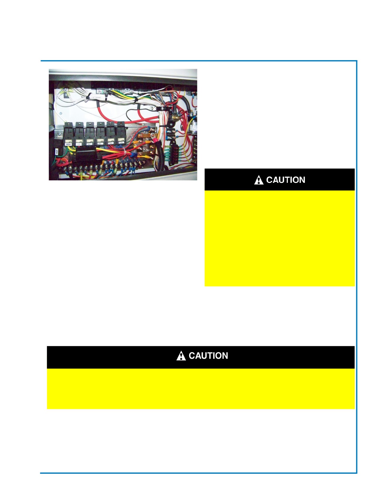
POWER DISTRIBUTION CENTER
The Power Distribution Center (Fuse Panel) provides
power to different electrical systems within the bus.
They are located throughout the bus. These places
are: Within the Dash, inside the Underfloor Luggage,
Battery Box and the “Pro Heat Compartment”.
Fig. 1-7 Power Distribution Center
ELECTRICAL POWER IS
ALWAYS “LIVE” IN THE POWER
DISTRIBUTION CENTER. USE
CAUTION WHEN PERFORMING
REPAIRS OR WHEN THE ACCESS
DOOR IS “OPEN”. NEVER
OPERATE THE BUS WITH THE
ACCESS DOOR “OPEN”, A SHORT
CIRCUIT TO THE ELECTRICAL
SYSTEM COULD OCCUR
IN CASE OF AN EMERGENCY
Hazard Warning Lights
Activate the Hazard Warning Lights. Refer to the GCA/ABC Operator’s Manual for instructions.
DO NOT tow unbraked vehicles of the combined weight of both vehicles
is more than the sum of the gross axle weight ratings (GAWRs) of the
towing vehicle. Otherwise brake capacity of the towing vehicle will be
conpromised, which could result in personal injury or death.
Towing
When it is necessary to tow the vehicle, make sure the following instructions are used to prevent
damage to the vehicle. Front Tow Hookup
Revised: October 2007
Page 05
Champion Bus, Inc. Maintenance

SECTION 1
General Information
FRONT TOW HOOKUP
1. Disconnect battery ground cable.
2. If vehicle is to be lifted and towed, remove drive axle shaft.
Failure to remove the drive axle shaft when towing the vehicle with the
rear wheels on the ground could result in damage to the transmission
and other components.
3. Attach to towing device. Due to the many variables that exist in towing, positioning the lifting and towing
devices is the sole responsibility of the towing-vehicle operator, who must be familiar with the towing
industry safety standards.
4. Lift the bus and secure the safety towing chains. If additional clearance is needed, remove the front wheels.
Before releasing the parking brake, make sure the connection to the
towing vehicle is secured, or chock the disabled vehicle’s tires. Failure
to do so could result in hazardous conditions because the vehicle could
suddenly roll and injury could occur.
5. Connect clearance, tail, and signal lights to the towing vehicle’s wire harness. Connect any special towing
lights required by local regulations.
6. Release the parking brake.
Rear Towing Hookup
1. Place the front tires straight facing forward and secure the steering wheel into this position.
2. Disconnect the battery ground cable.
3. Attach to towing device. Due to the many variables that exist in towing, positioning the lifting and towing
devices is the sole responsibility of the towing-vehicle operator, who must be familiar with the towing
industry safety standards.
4. Lift the vehicle and secure the safety towing chains, if additional clearance is needed, remove the
bumper extension, if equipped.
5. Connect clearance, tail, and signal lights to the towing vehicle’s wire harness. Connect any special
towing lights required by local regulations.
Revised: October 2007
Page 06
Champion Bus, Inc. Maintenance
SECTION 1
General Information
Vehicle batteries produce hydrogen gas and can create sparks, possibly
leading to anexplosion. DO NOT allow the vehicles to touch each other and
keep sparks, flames, cigarettes, etc. away from the batteries. DO NOT lean
over the batteries when making connections and keep all other persons
away from the batteries, otherwise severe personal injury could result from
explosion and or acid burns.
Make sure both starting systems have the same voltage outputs and avoid
making sparks. Otherwise the vehicle charging systems could be severely
damaged. Also DO NOT attempt to charge isolated, deep-cycled batteries with
jumper cables; follow the manufacturer’s `instructions when charging deep
cycle batteries.
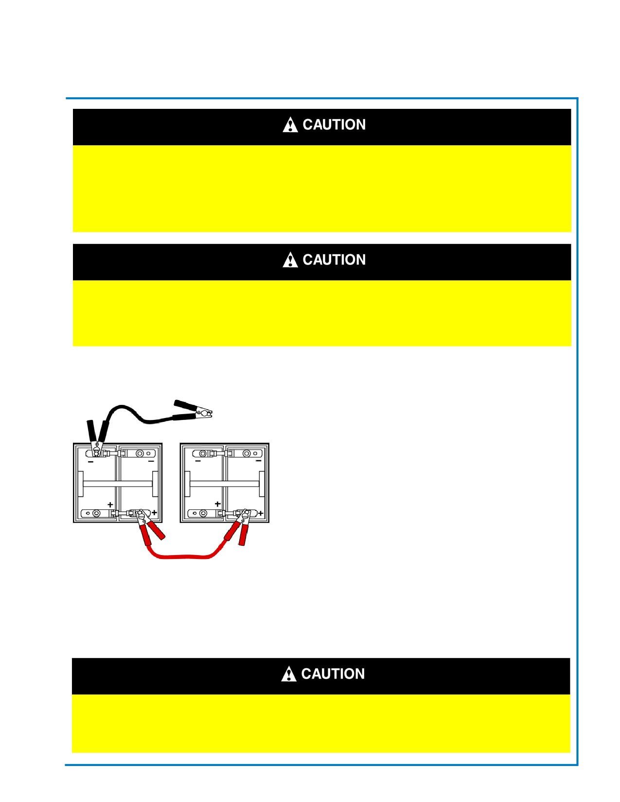
Emergency Starting with Jumper Cables
When using jumper cables, use the following instructions:
1. Apply vehicle’s parking brake and turn “OFF” any exterior or
interior lights that may be “ON” and any other electrical loads.
2. Connect the (+) positive cable end of the booster battery to
the (+) positive terminal of the discharged battery.
3. Connect the (-) negative cable end of the booster battery to
the (-) negative terminal end (ground) at least 12 inches (300mm)
away from the discharged batteries. The vehicle frame usually
provides a good ground. DO NOT connect the cable to or near
the discharged batteries.
4. Start engine from the booster batteries and let engine run a
few minutes to charge the discharged batteries.
Fig. 1-8 Battery Cable Connection
5. Shut “OFF” the engine, then attempt to start engine . DO NOT
operate the starter longer than 30 seconds and wait at least two (2)
minutes between starting attempts to allow the starter to cool.
6. When the engine starts. Let it idle a few minutes.
Perform the next tasks exactly as instructed and DO NOT allow the
clamp of one cable to touch the clamp of the other cable, otherwise a
spark could occur near a battery, possibly resulting in severe personal
injury from explosion and acid burns.
Revised: October 2007
Page 07
Champion Bus, Inc. Maintenance
SECTION 1
General Information
Emergency Starting with Jumper Cables (cont)
7. Disconnect ground (-) negative jumper cable from frame or other non-battery location, then disconnect
other end of (-) negative cable from booster battery.
8. Disconnect (+) positive jumper cable end from vehicle’s newly charged battery first; then disconnect other
cable end from booster battery.
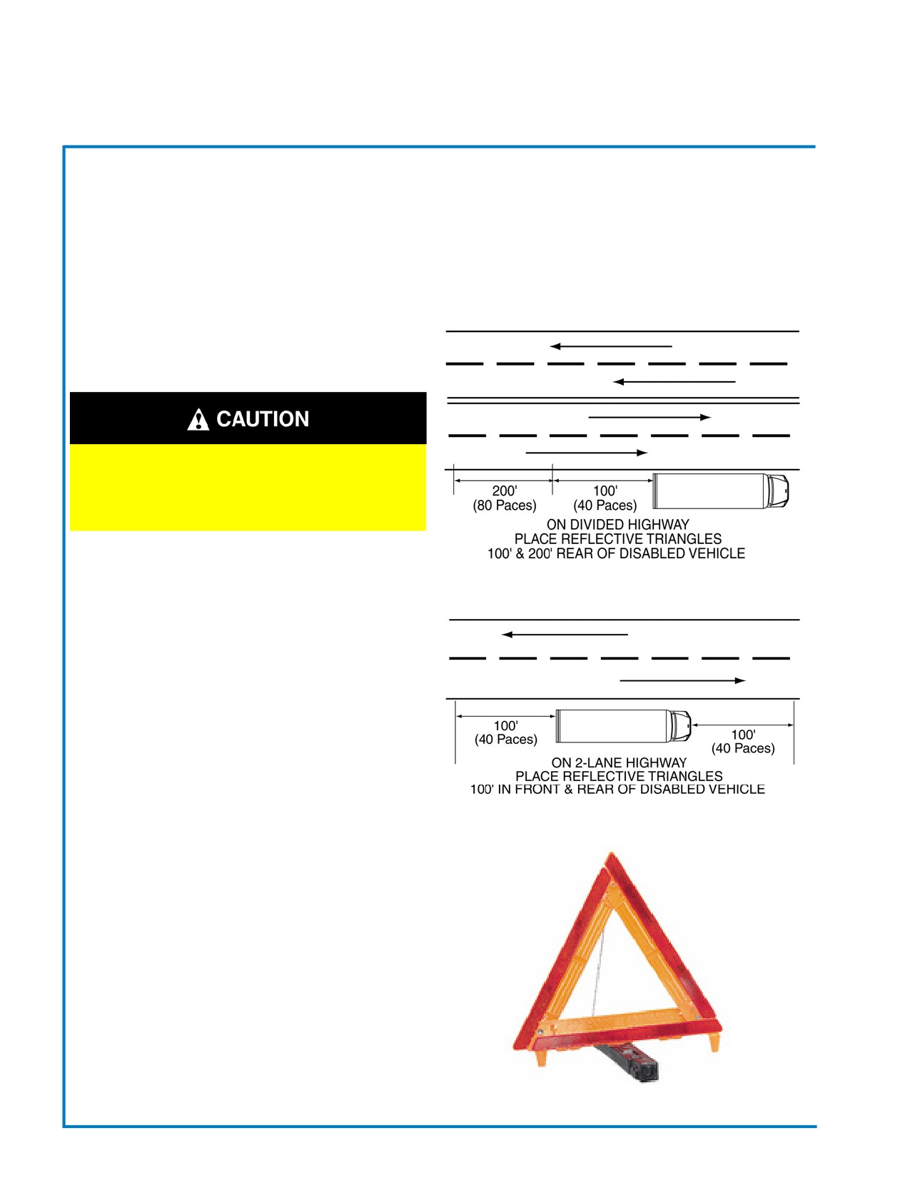
Reflective Triangle Warning Kit
BEFORE LEAVING DISABLED
VEHICLE ALWAYS ACTIVATE THE
VEHICLE’S EMERGENCY FLASHERS
Divided Highway
Emergency Reflective Triangle
Warning Kit
On a straight highway Two (2) Lane:
1. On side of road, place one (1) Reflective Triangle
100 ft. in front of disabled vehicle (approx. 40 paces).
2. Then place another Reflective Triangle 100 ft.
from rear of disabled vehicle (approx. 40 paces).
On a divided highway:
Two-Lane Highway
1. Place two (2) Reflective Triangles on side of road
one at 100 ft. and the other at 200 ft. from rear of
disabled vehicle. (approx. 40 paces & 80 paces)
To assemble Triangle:
1. Raise two (2) arms of triangle and snap pin into
slot.
2. Turn base 90° to it’s “Stop” position.
Fig. 1-10 Emergency Reflective Triangle
Revised: October 2007
Page 08
Champion Bus, Inc. Maintenance
SECTION 1
General Information
Running Out Of Fuel
Fuel is highly flammable. Whenever you approach a vehicle and a smell
of fuel is present, immediately shut off all engine and ignition sources.
Avoid causing sparks and stay away from arcing switches and equip-
ment. Extinguish any cigarettes, pilot lights, flames, or other
sources of ignition in the area. Immediately provide extra ventilation to
the area. DO NOT start the equipment or any other type of equipment
until the fuel leak is corrected and the area cleared of leaked fuel. Fail-
ure to perform these actions could lead to ignition of the fuel, which
could cause severe bodily harm and property damage and death.
If your vehicle runs out of fuel, stop the vehicle on a level surface away from traffic. The engine may be
restarted by adding at least two (2) gallons (8 liters) of fuel to the fuel tank. If the vehicle is not level, up to
six (6) gallons (22 liters) of fuel may be required. Prolonged engine cranking may be required to pump fuel
from the fuel tank to the engine before the engine will start. Diesel engines have “priming” pumps. See
your OEM Chassis Manual for this operation.
IMPORTANT
DO NOT crank the engine for more than 30 seconds at a time. Wait (2) two minutes after each try
to allow the starter time to cool. Failure to do so could result in starter damage.
If your vehicle will not start by cranking the engine, the fuel system may need to be primed. Contact your
service center for fuel system priming information.
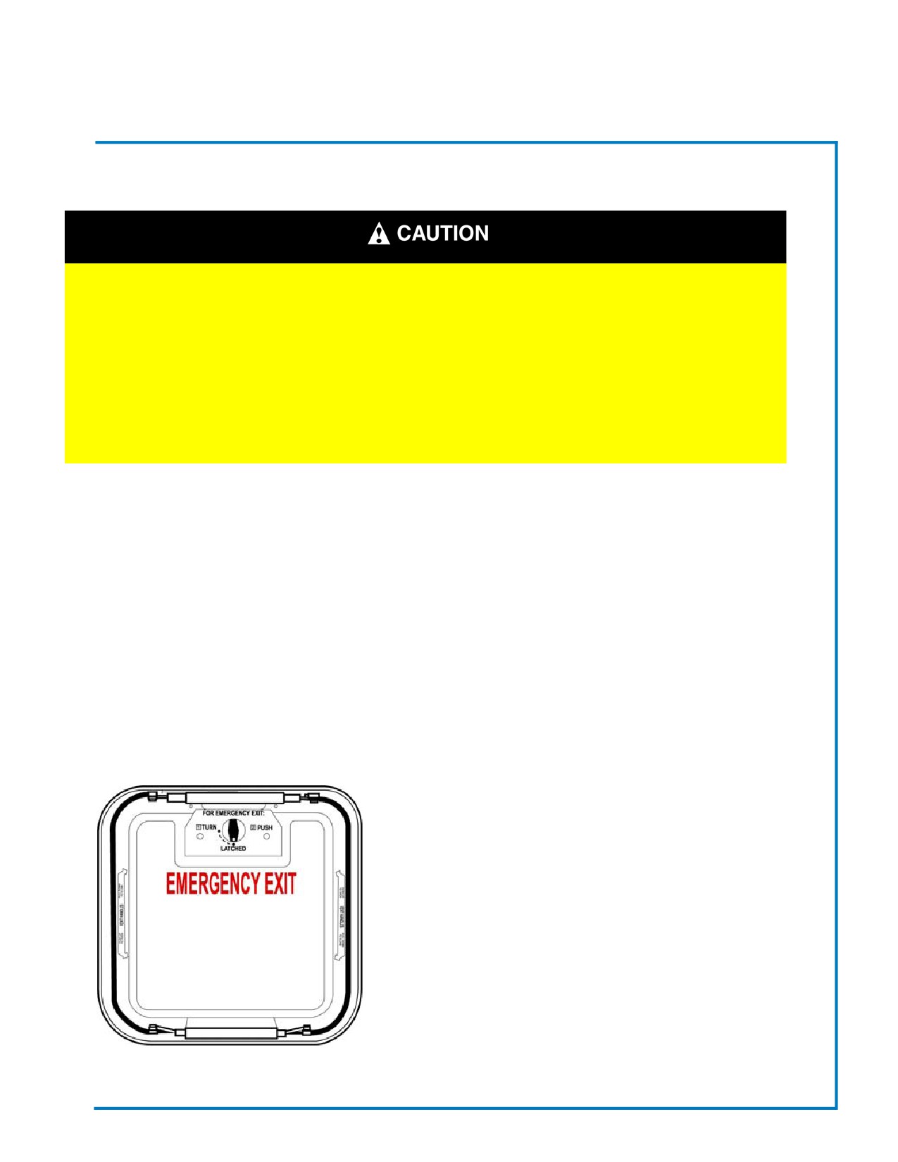
Emergency Escape Exits
Roof Escape Hatch
To open the roof top emergency escape hatch from the
inside of the vehicle, follow the steps listed below:
1. Turn the handle clockwise to the “OPEN”
position.
2. Push up on the hatch to open.
To close the hatch, pull down on the hatch on turn the
handle to the “Latch” position to secure.
Note:
The roof escape hatch can also be used for ventilation, sim-
ply push up at the sides of the escape hatch and it will pop
Fig. 1-9 Escape Hatch
up for ventilation. Pull down and it will snap shut to close.
Revised: October 2007
Page 09
Champion Bus, Inc. Maintenance
SECTION 1
General Information
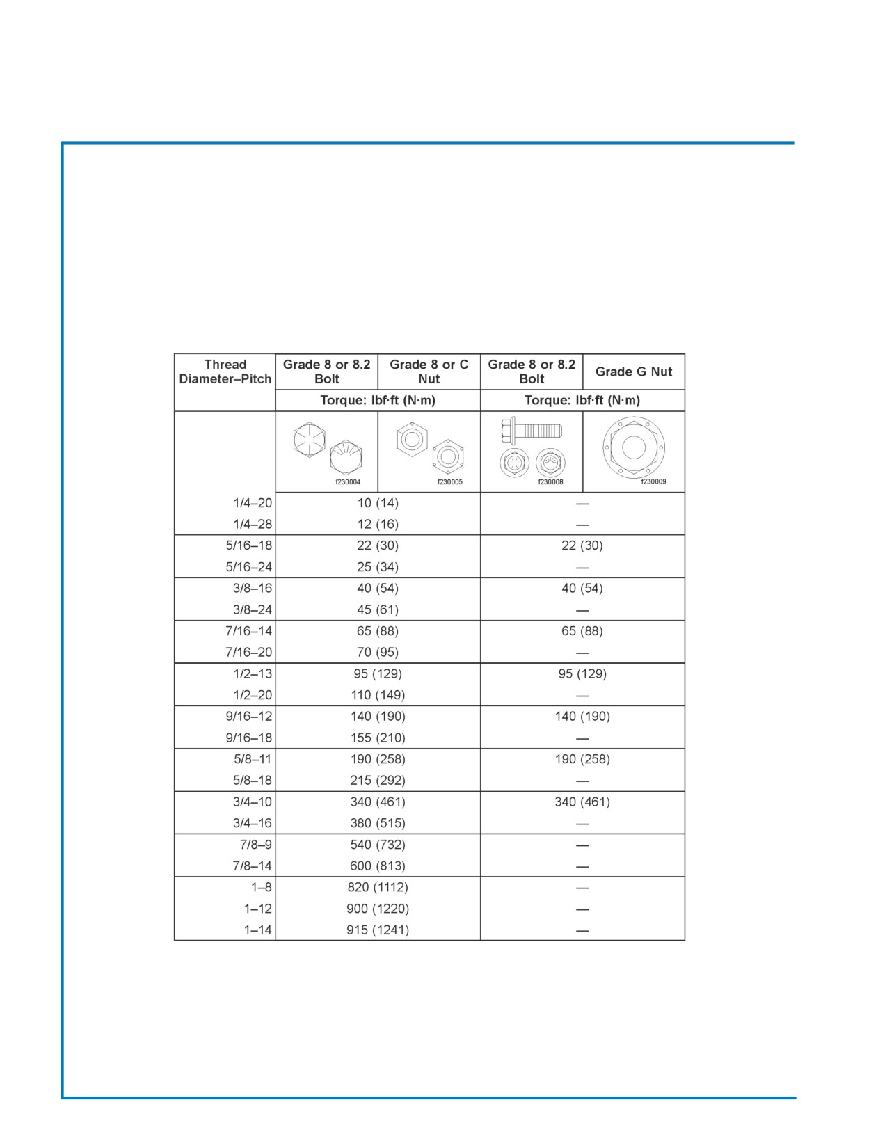
Bolt Torque Guide
Champion Bus, Inc and General Coach America, Inc uses American Standard, Grade 8 bolts.
The following is to be used as a generic guide for bolt torque measurement. Champion Bus, General Coach
and any affiliates or dealers do not take responsibility for any of the infornation.
from Freightliner Maintenance Guide
Revised: October 2007
Page 10
Champion Bus, Inc. Maintenance
Notes:
Section 2 - Chassis
LUBRICATION
13
FILTERS
13
FUELS
13
FUELING THE VEHICLE
13
WHEELS & TIRES
14-15
TIRE ROTATION
15
CHANGING A FLAT TIRE
15-16
JACKING LOCATIONS
16
SECTION 2
Chassis
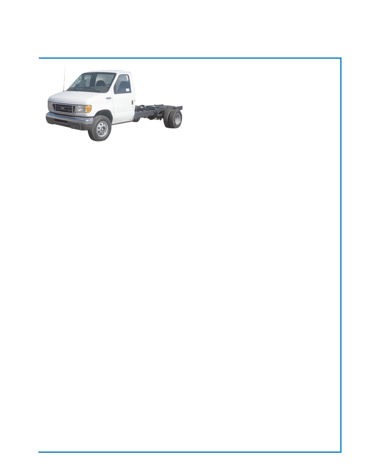
GENERAL INFORMATION
Champion Bus, Inc. buses are built on a variety of
chassis. This Model Bus is built on Ford E-350 or
E-450 model chassis.
For more specific chassis information, all persons
responsible for the operation and maintenance of the
vehicle should read and understand the guidelines
presented in the OEM Chassis Owner’s/Maintenance
Manuals that are included with your vehicle. All
questions regarding chassis operation or maintenance
should be directed to your bus dealer or a local chassis dealer.
LUBRICATION
The chassis manufacturer’s recommendations should be followed regarding chassis and engine lubrication
schedules and specifications. Note that special requirements may exist for severe driving conditions such
as heat, cold, dust, mud, or sustained high power output.
FILTERS
Filters should be changed on a regular basis, according to the manufacture’s specifications, using only
approved filters. Note that frequently driven buses may require more frequent filter changes to maintain
proper operating systems.
FUELS
Use only high quality low sulfur diesel fuel that meets or exceeds the minimum specifications of the engine
manufacturer. Failure to do so may result in damage to engine components.
FUELING THE VEHICLE
Use only fuels that meet or exceed the engine manufacturer’s specifications. Fuel should be free of water and
other contaminants. Avoid running the fuel tank near “Empty” as this can lead to condensation and fuel system
problems.
• Clean the exterior of the fuel cap and filler spouts before removing cap.
• Remove the fuel cap, place the fuel nozzle in the filler spout and proceed with fueling the vehicle.
• When full, remove fuel nozzle, replace fuel cap, and turn to tighten. Remove any spilled fuel from bus body
** Do NOT “top off” fuel tank.**
Revised: October 2007
Page 13
Champion Bus, Inc. Maintenance
SECTION 2
Chassis
USE OF UNAUTHORIZED LUBRICANTS, FILTERS, FLUIDS, FUELS OR PARTS AND/OR
NEGLECT OF SCHEDULED MAINTENANCE MAY VOID THE WARRANTIES FOR YOUR
VEHICLE.
WHEELS & TIRES
Your bus is equipped with high-quality tires that meet the vehicle usage specifications. Tires are warranted by
the tire manufacturer as described in the documents provided with your vehicle.
• Inspect tires daily for evidence of damage such as cuts, scuffs, cracked sidewalls or any signs of rubber
separating from the tire. Also, inspect for abnormal wear and report any problems immediately.
• Check tire inflation pressure at least once per week while the tire is cold. If necessary, adjust the tire
pressure by adding or removing air until the designated pressure range for the tire is achieved. Always use
an accurate tire pressure gauge.
• Never attempt to check or adjust tire pressure while the tire is hot. Tire pressure increases with higher
temperature and subsequent readings will be faulty. Under-inflation may result from hot tire pressure check.
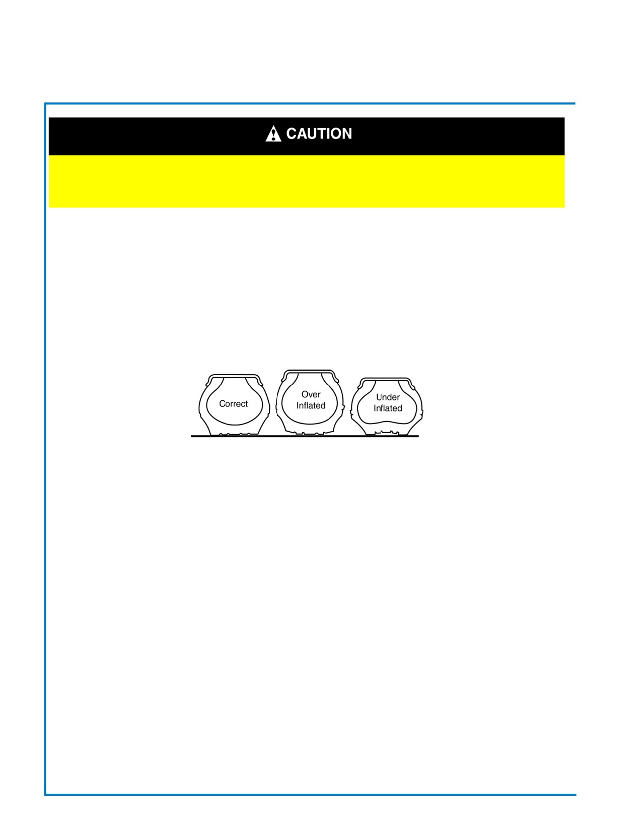
• Note that low tire pressure reduces the load carrying capacity and may lead to the overheating of tires and/
or potential tire failure. Similarly, excessive tire pressure affect vehicle handling and increases the risk of
tire failure.
• Tires should be rotated on a regular basis using a recommended rotation pattern. Rotating tires should result
in more uniform tread wear and may lengthen tire life. However, do not put a worn tire and a high-tread tire
on the same axle. Keep tire treads matched as closely as possible.
• If abnormal wear occurs, have the steering and wheel alignment checked by qualified service technicians.
Tire rotation will only temporarily disguise the problem if steering or alignment if off.
• With dual wheels, the outside tire will wear faster than the inner tire. To equalize wear, reverse the tire
positions on a regular mileage schedule. If one dual wheel must be replaced, always replace both duals to
keep wear equalized.
• Keep Lug Nuts tight. Loose lug nuts will quickly ruin a wheel and can result in loss of the wheel, thus
creating a dangerous situation for driver and passengers. If you suspect a loose wheel, pull off the road and
inspect the lug nuts immediately.
• Inspect lug nut at every chassis lubrication and inspection. If your bus is fitted with wheel covers, remove
them prior to inspection. Lug nuts should always be installed clean and dry. Never lubricate lug nuts. Hubs
should be clean dry, and free of rust and excess paint. Firm metal-to-metal contact is necessary to ensure
that wheels remain securely fastened.
Revised: October 2007
Page 14
Champion Bus, Inc. Maintenance
SECTION 2
Chassis
WHEELS & TIRES (cont.)
• On new dual wheels, re-torque lug nuts at 100 miles and again at 500 miles.
• Replacement tires should equal or exceed load specifications of the original equipment. Do not mix tire
sizes and do not mix bias ply and radial tire construction. Dangerous vehicle handling conditions may
result.
• Wheels should be replaced if bent, badly rusted, or if loose lug nuts have caused excessive wear in the hub
area. Use only replacement wheels approved by the chassis manufacturer. Make sure the new wheels match
the original wheel size and load carrying capacity and that they are designed for the same size and type of
tires needed on your vehicle.
Tire Rotation
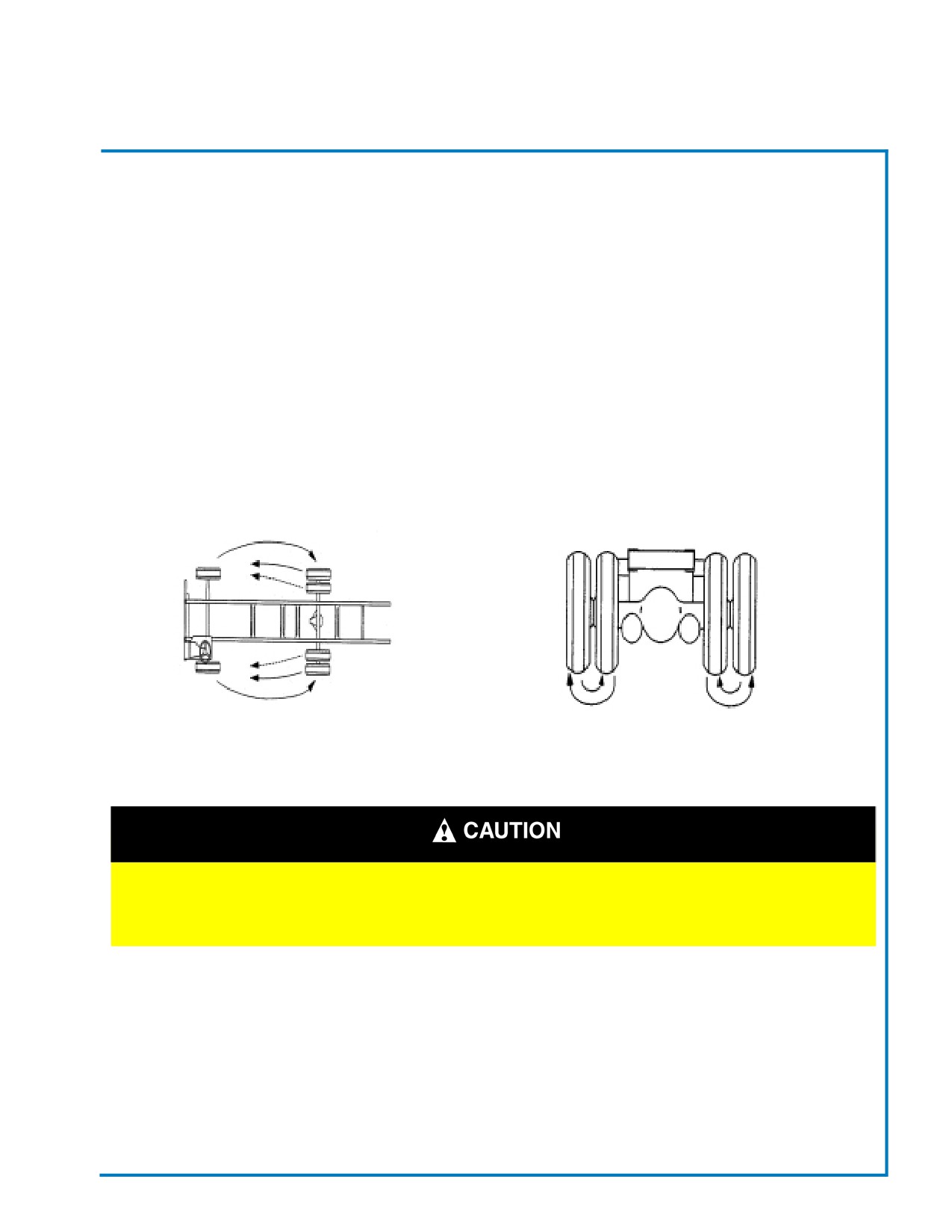
If tires are wearing irregularly, rotate them. If the front steering axle tires become irregularly worn, move them
to the drive axle. Have the front axle alignment checked to determine the cause of irregular tire wear. In a dual
assembly, if one tire wears faster than it’s mate, reverse the positions of the two tires.
For more information on tire specifications, refer to the Recreational Vehicle Tire and Care Guide provided with
your chassis manuals. OEM Manuals override all information provided by ABC and General Coach.
If a flat tire occurs while driving, gradually decrease vehicle speed.
Holding the steering wheel firmly, move to a safe place on the side of
the road.
Changing a Flat Tire (Refer to your OEM Chassis Manual for Jacking)
1. If possible, stop the vehicle on a level surface, away from traffic.
2. Apply the parking brake and turn “OFF” the ignition.
3. Turn “ON” the emergency flashers.
4. Remove spare tire, jack, handle, and lug wrench from storage, if equipped.
Revised: October 2007
Page 15
Champion Bus, Inc. Maintenance

SECTION 2
Chassis
5. Block the diagonally opposite the wheel being changed.
Note:
The jacking point for the front and rear wheels is directly under the axle.
6. Place the jack on a solid surface. Insert the jack handle and pump the handle to slightly raise the
vehicle. DO NOT RAISE THE WHEEL OFF THE GROUND. Loosen the wheel lug nuts, but do not
remove them.
Note:
The dual rear wheels are attached using two-element lug nuts. The larger nut retains the outer dual. The
inner square stud retains the inner dual. Remove and install these nuts separately. The rear dual outer lug
nut must be loosened to check and retighten the inner nut.
7. Raise the vehicle until the wheel is off the ground. Remove the lug nuts and the wheel.
8. Install the spare wheel and lug nuts. Make sure the beveled sides of the nuts face inward.
9. In a “star” pattern, tighten the nuts evenly until snug.
10. Lower the vehicle until the wheel touches the ground. Tighten the lug nuts in the same pattern
126 to 170 ft/lbs. (170 to 230 N·m)
Failure to tighten the wheel nuts in a star pattern can result in
high brake disc runout, which will speed up the development brake
roughness, shudder and vibration.
11. Finish lowering the vehicle to the ground, then remove the jack.
12. Remove the block from the opposite tire of the repaired tire, then stow the jack, handle and lug wrench.
13. After operating the vehicle for 50 to 100 miles (80 to 160 km), retighten the nuts to 126 to 170 ft/lbs.
(170 to 230 N·m)
JACKING LOCATIONS
Lift vehicle at locations painted Yellow at either the front axle or rear axle. At Front Axle the Yellow painted
areas are located near the wheel assemblies. The Rear Axle Yellow painted locations are near the rear wheel
assemblies.
Raise the vehicle with an automotive type jack at the points painted “Yellow” by the manufacturer. Use these
lifting points to avoid any vehicle damage, serious injury, when components are being removed from the
vehicle.
Refer to your OEM Chassis Maintenance Manual provided with your bus for more information.
Revised: October 2007
Page 16
Champion Bus, Inc. Maintenance
Notes:
Section 3 - Flooring & Interior Trim
FLOORING
19
RUBBER FLOOR COVERING
19
INTERIOR WALLS & CEILING
19
MODESTY PANELS
20
INTERIOR TRIM
20
WIRE HARNESS ROUTING
21
SECTION 3
Flooring & Interior
FLOORING
General Coach America, Inc. buses are constructed of ¾” exterior grade plywood, supported by steel cross-
members. This construction provides a lightweight, durable floor that insulates passengers from road noise and
the elements.
RUBBER FLOOR COVERING
The standard floor covering is transit-type and/or smooth rubber matting. Rubber flooring is durable and easy
to clean. With proper care, rubber flooring covering should last the life of the bus.
• Clean rubber flooring with a damp mop. A soap/water solution will clean most spills and stains. Tough
stains may require gentle scraping or use of a scrub brush.
• DO NOT clean bus floors by spraying water from a hose. Water may leak under the flooring seal and
cause floors to deteriorate.
• DO NOT use petroleum-based solvents on rubber flooring. They may present a fire hazard and will
damage the floor rubber.
INTERIOR WALLS & CEILING
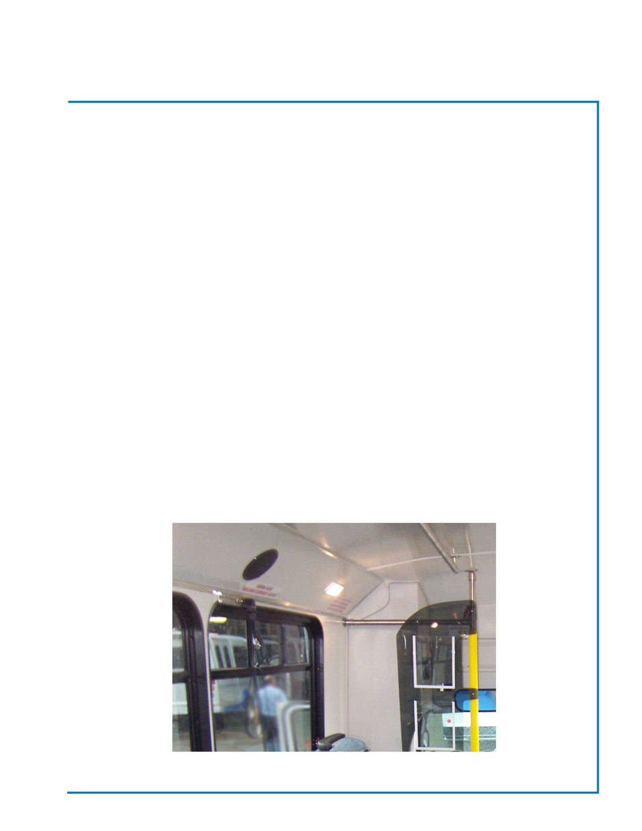
• Interior Walls and Ceiling Panels should be cleaned every week with a mild soap/water solution. Foam type
cleaners and many plastic and vinyl cleaners also work well to remove any marks or stains from walls or
ceiling.
• Always follow the directions on cleaner labels and dry-off damp surfaces as soon as possible to
remove excess liquid.
Fig. 5.1 - Interior Walls & Ceiling
Revised: October 2007
Page 19
Champion Bus, Inc. Maintenance
SECTION 3
Flooring & Interior
MODESTY PANELS
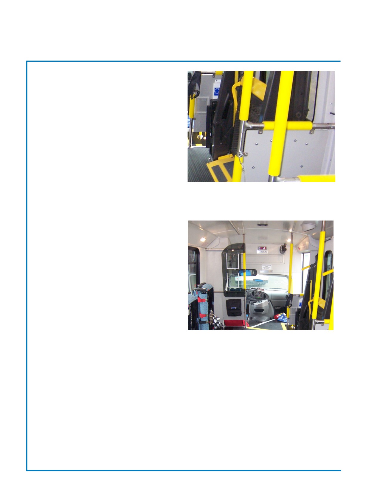
Modesty Panels are provided for passengers’
privacy and protection. The standard modesty panels
are attached to the stanchions at the front of the
passenger area and are covered with material that
coordinates with the bus’s interior sidewall color and/
or Feature Panel pattern.
• Modesty Panels should be cleaned on a weekly basis
with a mild soap/water solution. Many plastic and vinyl
cleaners will work as well.
• Inspect Modesty Panels daily for secure attachment.
Screws at attachment points may work themselves
loose causing the panel to shake and/or fail. Loose
Fig. 5.2 Modesty Panels
screws should be tightened, as needed, to assure
safety.
INTERIOR TRIM
The driver operates the bus from the cab area.
To control its many systems, wire harnesses route from
the cab area to other areas throughout the bus. The
interior trim panels help to finish off the interior of the
cab but also cover and protect the wiring harnesses.
• Interior trim panels should be cleaned every week or
when needed. Interior Trim Panels may be cleaned
with a soap/water solution or a vinyl cleaner (follow
manufacturer’s directions).
• Avoid soaking Interior Trim Panels with
cleaning solutions as deterioration may result.
Fig. 5.3 - Interior Trim
Revised: October 2007
Page 20
Champion Bus, Inc. Maintenance
SECTION 3
Flooring & Interior
WIRE HARNESS ROUTING
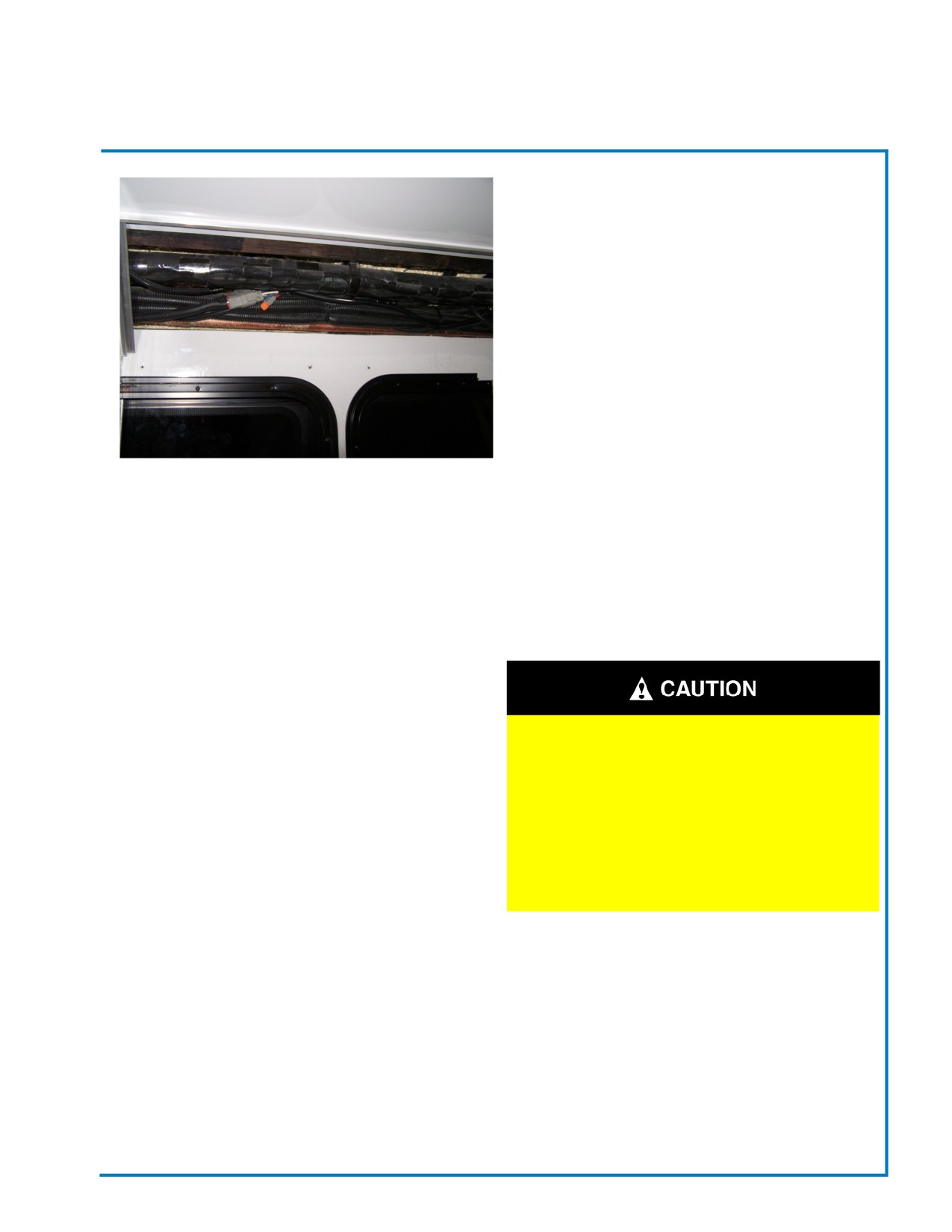
The busses Wire Harnesses are routed behind
the Interior Sidewalls, Ceiling and the flooring as
indicated in the photos, Most wiring can be accessed
by removing the trim panels. Your local dealer can
recommend the best removal procedures.
Because the gap between the interior trim panels and
wiring harnesses is minimal, DO NOT puncture the
panels or secure anything to the trim panels as the
electrical system may be easily damaged and severe
problems may result.
Some wiring harnesses and A/C lines run down along
the back corners of the bus. Interior Trim Panels can
Fig. 5.4 - Typical Ceiling Wiring
be removed to access the wiring and A/C lines, if
necessary.
Kick panels run along the floor to cover some wiring
and other wiring harnesses are routed behind the
ceiling panels. Wiring for speakers, interior lights and
other systems are routed inside the overhead parcel
racks.
BECAUSE WIRING HARNESS ARE
LOCATED BEHIND THE CAB AREA
INTERIOR TRIM PANELS AVOID
PUNCTURING THE TRIM PANELS OR
SECURING ANYTHING TO THE PANELS
WITHOUT FIRST CALLING YOUR DEALER
FOR ASSISTANCE. SEVERE DAMAGE TO
THE BUSES SYSTEMS MAY RESULT.
Revised: October 2007
Page 21
Champion Bus, Inc. Maintenance
Notes:
Section 4 - Seats
GENERAL INFORMATION
24
DRIVER’S SEATING
24
PASSENGER SEATING
24
MAINTENANCE
25
PASSENGER SEATING & SAFETY REQUIREMENTS
25
SAFETY RESTRAINTS
25
WHEELCHAIR TIEDOWNS
26
HOLDSWORTH FABRIC CARE
26
FABRIC MAINTENANCE
26
CLEANING OF UPHOLSTERY
26-28
TRIM MAINTENANCE
28
PASSENGER SEATS ADJUSTMENTS
29
DRIVER’S SEAT
30-31
SECTION 4
Seats
GENERAL INFORMATION
General Coach America, Inc. offers a wide variety of high-quality standard and custom seating options. How-
ever, because of the number of seating alternatives, “standard” seating features are defined by the bus owner.
Regardless of seating styles, all seating meets or exceeds federally established safety standards. Seat frames
meet FMVSS #207 for crash protection and all seat coverings meet FMVSS #302 for burn resistance.
Seat coverings are available in either vinyl, fabric or vinyl/fabric combinations and numerous colors and de-
signs. Seat cushions are made of dense, non-allergenic, air-blown urethane foam and offer a comfortable ride.
General information regarding seating options and maintenance is included in this section. Specific option
details also follow in this section, as provided by the seat manufacturer.
DRIVER’S SEATING
Many driver’s and co-pilot’s seating options are available with General Coach America, Inc. buses. Driver’s
seats may have a manual slide base or a two-way or six-way electric adjustable base and a fixed or swivel
base. A reclining bucket seat can also be chosen as another option.
Details regarding your particular driver’s seat, is provided by the seat manufacturer, by visiting their website.
Please refer to this information for operational and maintenance instructions.
PASSENGER SEATING
Passenger seating is available in bench, bucket, reclining bucket, folding, and perimeter styles. While most
passenger seating is modular in design and can be removed for repair, replacement, or reconfiguration of the
passenger seating area, seats are fastened securely in place for the safety and comfort of all passengers.
Details regarding passenger seating options for your bus follow this section. Please refer to this
information, provide by the seat manufacturer, for operation and maintenance instructions.
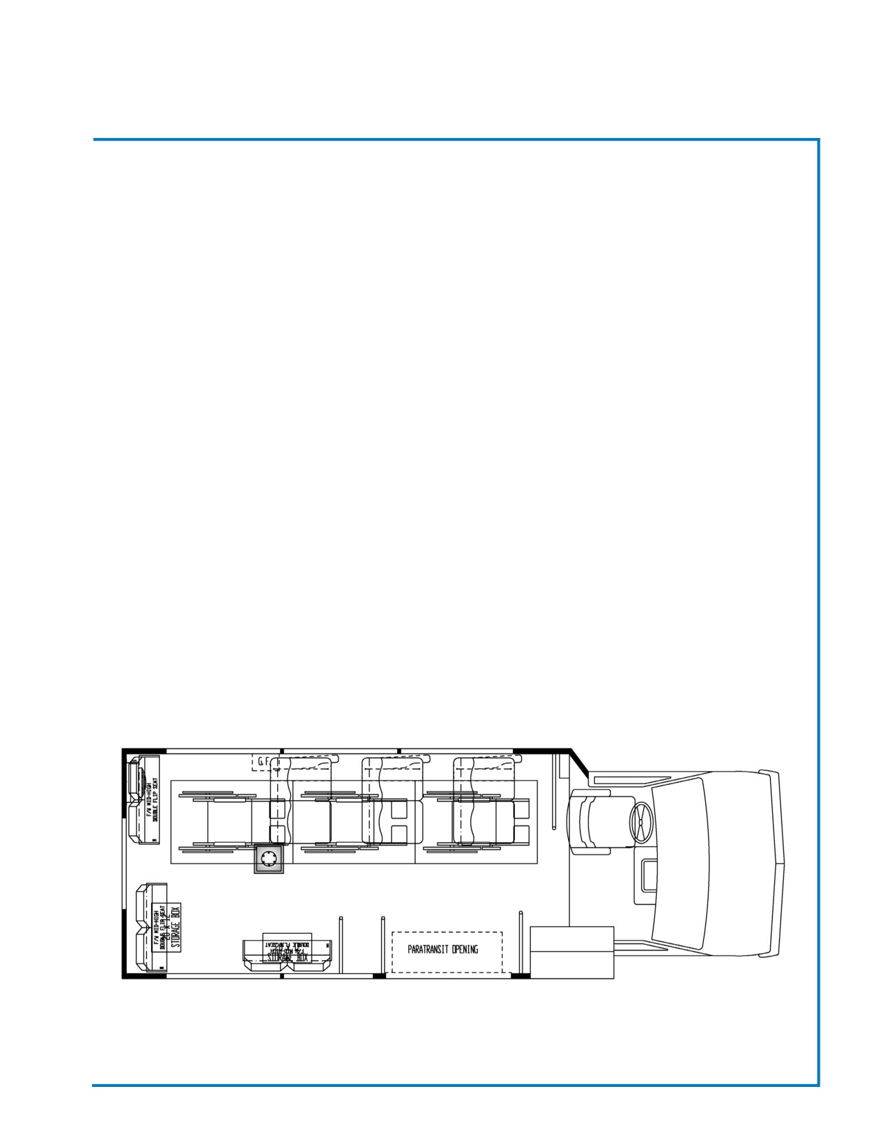
Figure 4.1 Seating Floor Plan
Revised: October 2007
Page 24
Champion Bus, Inc. Maintenance
SECTION 4
Seats
MAINTENANCE
• Inspect the seating area daily for tears, rips, or stains. Check seats for secure attachments. Tighten
any loose bolts to assure safety and prevent rattling.
• Vinyl seats should be wiped down one to two times per month with a soap and water solution of other
mild cleaning agent recommended for vinyl. Use of stronger solvents on vinyl seats is not
recommended as they reduce the strength of the vinyl and cause premature cracking.
• Vacuum fabric-covered seats one to two times per month to remove loose surface dirt as well as dirt
that has settled to the bottom of the fabric pile. A commercial grade or heavy duty vacuum is
recommended. Spot clean stains (as soon as possible) with a soap and water solution or mild cleaning
agent recommended for fabric.
• Steam-clean fabric cover seats every six months to restore the fabric pile and to remove stains and
odors. Spot clean stains, if necessary, before steam-cleaning.
Passenger Seating & Safety Requirements
Champion Bus, Inc. offers a wide variety of custom seating options. Regardless of your seating configuration,
seating meets or exceeds federally established Safety Standards. Weight Distribution and Payload Certifica-
tion. This vehicle, as manufactured, conforms to the weight distribution and payload requirements in Mid-Size
Bus Manufacturers Association (MSBMA) recommended practice 001.
It is the user’s responsibility not to load the vehicle above the number of designated seating positions and
luggage allowance.
Configuration A:
Manufacturer: General Coach America, Inc. Imlay City, Michigan
VIN/Body Serial #: _____________________________________
Number of designated seating positions: 40*
Number of designated Wheelchair positions: 0
Note: Number of designated seating positions is calculated using 150 lb. (68 KG) per designated seating
position, 20lb. (91KG) for wheelchair position, including driver. Luggage allowance is calculated using 5 lb.
(11.3KG) of luggage per designated seating position if vehicle is equipped with luggage compartment and 5 lb.
(2.3KG) if vehicle is equipped with an overhead shelf.
All seating exceeds all FMVSS standards. For identification of seating manufacturer, please see the manufac-
turer label located underneath each seat assembly.
*Number of Seating Positions May Vary depending on specific model of bus. Number is derived from Maxi-
mum amount of passengers Plus Driver.
SAFETY RESTRAINTS
FMVSS Compliance #209 specifies seat belt assembly characteristics in regards to adjustability, width,
colorfastness, breaking strength, elongation and resistance to abrasion, light and microorganisms.
Performance requirements to include ability of the complete assembly to withstand prescribed forces and to re-
sist excessive stretching. OEM meets these requirements. General Coach America, Inc. does not change OEM
seat belt assemblies, OEM seat belts are attached according to OEM specifications. Passenger seat belts have
met the testing requirements of FMVSS #207.
Revised: October 2007
Page 25
Champion Bus, Inc. Maintenance
SECTION 4
Seats
WHEELCHAIR TIEDOWNS
Install wheelchair restraints in accordance with OEM manufacturer’s Driver/Operator Instruction Guide
included with the vehicle.
Holdsworth Fabric Care
Holdsworth have established the following care and maintenance instructions for fabrics.
Considerable thought and development work has gone into the production of our fabrics to enable them to
withstand the rigorous use on public transport vehicles. We felt therefore, a few hints on the care and cleaning
would help you to obtain the best possible life from your fabric.
One of the main advantages of these fabrics is their construction which allows dirt to fall to the base of the pile.
This presents a relatively clean surface to your passenger which is obviously very important.
Routine Cleaning.
All that is required to remove the dirt is gentle beating with the hand or the back of a brush. This will bring the
dirt to the surface where it is easily removed by a vacuum cleaner or a soft brush. It is preferable to vacuum or
brush in the direction of the pile which can easily be recognized by running a hand lightly over the pile. Clean-
ing should be carried out as often as possible. If the fabric becomes excessively dirty, then particles of grit will
cause gradual wear to take place, thus reducing the life of the moquette.
Steam Cleaning.
Occasional steam cleaning will breathe new life into tired upholstery. Portable steam cleaners are readily avail-
able from hire shops to rent or buy, and we have many examples showing how a vacuum and steam clean
can rejuvenate a drab interior. (The need to follow safe operating procedures when steam cleaning is vital to
prevent risk of scalding.)
FABRIC MAINTENANCE
With proper care your upholstery will provide years of beautiful service. To help keep your upholstery looking
new, certain precautions and cleaning instructions should be followed. By giving your upholstery a little extra
attention, it will stay looking great for years!
According to the Environmental Protection Agency your upholstery serves as a magnet that collects a variety of
pollutants and contaminants from various sources. Internal sources include air conditioners, heaters, tobacco
smoke and food particles. Outdoor sources include pollen and spores from trees, plants and other vegetation
as well as exhaust fumes from cars, fireplaces and other form of pollution.
Satisfactory results are usually achieved by cleaning with a non-water-based foam cleaner, provided that
manufacturer’s directions are carefully adhered to. Any product or technique should always be tested on an
inconspicuous area before attempting overall cleaning.
CLEANING OF UPHOLSTERY
The seat cushion and back covering may be fabricated of different materials, consisting of both synthetic and
natural fabrics. Vinyl coated fabrics cannot be machine washed (laundered).
For cleaning of the seat upholstery in view of the above limitations, the following procedure is suggested:
Revised: October 2007
Page 26
Champion Bus, Inc. Maintenance
SECTION 4
Seats
Woven Fabrics
•
Frequent and thorough vacuum cleaning.
•
Occasional steam cleaning.
•
To the cover (not removed) apply a thick layer of soap (non-alkaline) or approved foam type
cleaner. Suds are to be scrubbed into fabric using a stiff bristle brush or a sponge.
•
After scrubbing sponge the suds from the fabric with a clean sponge or cloth dampened with
water. Rinse sponge or cloth frequently with clean water.
•
Do not water soak fabric, as this will cause shrinkage.
Method 1
Apply a non-inflammable solvent (trichlorethylene) with a clean, white, absorbent material, treating small areas
working from the outer edge towards the center of the stain. Blot frequently with a dry cloth to avoid rings.
*OPEN WINDOWS AND DOORS TO ALLOW FUMES TO DISPERSE.*
Method 2
Sponge the stain with a solution of household detergent and lukewarm water. DO NOT SOAK. Follow this by
rubbing with a damp cloth, rinsing cloth between each treatment.
Warning:
DO NOT USE SOAP, WASHING POWDER, AMMONIA, SODA,
BLEACH OR ANY PRODUCTS WHICH CONTAIN THEM.
Alcoholic Liquids
Sponge with water followed by Method 2
Battery Acid
Saturate with a solution of sodium bicarbonate, leave for several minutes before drying out. It is important for
the above treatment to be carried out immediately to avoid serious damage to the moquette.
Beverage Stains
Use Method 1. If stain persists, try methylated spirits.
Blood Stains
Use Method 2
Burns
Scrape blackened area with a knife and treat with Method 2. Extensive burns require expert attention.
Chewing Gum
Soften with cyclohexanone and scrape off carefully with a knife.
Cosmetics
Use Method 1, followed by Method 2.
Writing Ink
Use Method 2. If brown stain remains, treat as for rust.
Revised: October 2007
Page 27
Champion Bus, Inc. Maintenance
SECTION 4
Seats
Copying Ink
Treat with methylated spirits, blotting frequently to avoid ink spreading. Use cleaning Method 2 to complete the
treatment.
Ballpen Ink
Treat as copying ink.
Marking Ink (Felt-tipped pens)
Treat with Methyl Ethyl Ketone (M.E.K.), followed by Method 2.
Oil, Grease and Paint Marks
Remove surplus substance with a knife or spoon, then treat with Method 1, followed by Method 2. Should
stains reappear, repeat cleaning process.
Rust
Use Method 2, followed by a warm solution of oxalic acid. Complete treatment by sponging with water.
Tar
Soften with benzene and then treat with Method 1, followed by Method 2.
Urine
Use Method 2.
Vomit
Use Method 2.
NOTE: Prompt and correct cleaning will remove most stains. Wrong treatment will only increase the damage.
In cases where there is doubt, always seek expert advice. Information is to the best of our knowledge true and
accurate, but all recommendations or suggestions are made without guarantee since the conditions of use are
beyond our control.
We suggest that no matter the type or size of the stain, the cleaning process should go step
by step, You should start using the easy & simple to the complex solvents. In all cases, we
suggest to clean and brush in the pile direction.
Trim Maintenance
Cleaning of trim parts - Aisle End Panel & Rear Shell
Minor stains may be removed from trim parts with a good quality toilet soap. More severe cleaning problems
require the use of diverse cleaning agents and polishes. Most household cleaners, automotive waxes, and
polishes can be adapted to this job. Solvents and spray type household cleaners containing hydrocarbons, will
attack A.B.S. materials and should be used sparingly, if at all.
A cleaning solution should be applied sparingly with a clean, relatively dry cloth and wiped over the material
gently. It is recommended that the cleaning be accomplished by repeated applications of the cleaner rather
than one heavy application. All normal soaps and detergents may be considered safe for removing dirt and
grease from A.B.S. materials.
CAUTION:
Never soak panels in cleaning solution or allow them to remain
wet with solution for any length of time.
Do not use waxes which dry with a bloom as they are extremely
difficult to remove after application
Revised: October 2007
Page 28
Champion Bus, Inc. Maintenance
SECTION 4
Seats
PASSENGER SEATS ADJUSTMENTS
Passenger seat positions are non adjustable. Modifying position of seats may cause vehicle to exceed GVWR.
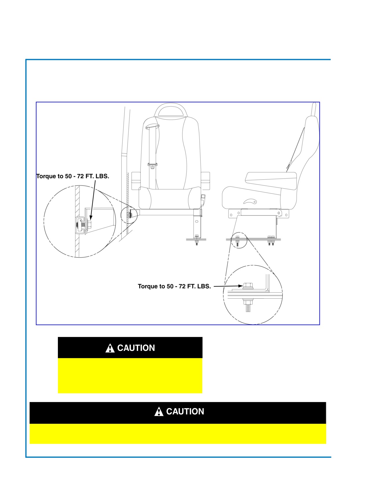
Figure 4.2 - 3pt. Mid-High Recliner Seat Shown (Others Similar)
MAKE SURE ALL BOLTS ARE ENGAGED
AND TORQUED TO THEIR
SPECIFICATIONS BEFORE ALLOWING
PASSENGERS TO OCCUPY THE SEATS
DO NOT MODIFY THE STRUCTURE OR POSITION OF ANY SEAT. MODIFYING SEATS MAY VOID
MANUFACTURES’ WARRANTIES, RAISE LIABILITY ISSUES, AND ENDANGER PASSENGERS.
Revised: October 2007
Page 29
Champion Bus, Inc. Maintenance
SECTION 4
Seats
The following material was supplied by
RECARO North America…
PREVENTATIVE MAINTENANCE SCHEDULE
ERGO METRO DRIVER’S SEAT
This maintenance schedule is instended to serve as a guide for inspection and service.
This schedule is not a complete list of all-possible inspections or services required. Action should be taken immediately
whenever a problem with the seat occurs.
The instervals of inspection or service that have been established should be considered maximum intervals, and shorter
intervals may be necessary depending on the enviroment or particular situation in which the vehicle is operated.
The M3035 is not equipped with a Recaro brand seat. However, the following information has value.
MILE S
6,00
0
12,000
24,00
0
48,000
ITE M
TYPE OF INSPECTION OR SERVICE
KM S
11,000
22,000
43,00
0
76,000
HOUR S
1200
2400
4800
9600
Section
1
Seat Belt Assembly
Check Anti-Cinch on Retractor
X
X
X
X
Check for Wear on Belt
X
X
X
X
Check for Proper Locking of Seat Belt Latch
X
X
X
X
Check Torque of Mounting Nuts
(37 FT-lbs)
X
X
Section
2
Tracks
Manually Check Fore and Aft Travel of Tracks
X
X
X
X
Visually Check for Dirty or Non-Lubricated Tracks
X
X
X
Lubricate with Grease
(Premium Moly-Lith Grease)
X
X
X
Check Bolts for Correct Torque
(16 FT-lbs.)
X
X
Check Tracks
f
X
X
X
X
Check Tracks
f
X
X
Check Auto Actuator Switch
f
X
X
X
X
Section
3
Control Panel
Check for Dirt in Air Switches
X
X
Check Tightness of Control Panel Attachment Screw s
X
X
Check Air Lines into Panel for Wear or Cracks
X
X
Revised: October 2007
Page 30
Champion Bus, Inc. Maintenance
SECTION 4
Seats
MILE S
6,000
12,000
24,000
48,000
ITE M
TYPE OF INSPECTION OR SER VICE
KMS
11,000
22,000
43,000
76,000
HOUR S
1200
2400
4800
9600
Section
4
Suspension
Check “UP” and “DOWN” Travel of Suspension
X
X
X
X
Check Airlines
f
X
Check
f
X
Check Rake Adjustment
f
X
X
X
X
Check Bellows
f
X
X
Check Air Springs
f
X
X
Inspect Shocks
f
X
X
Check Shock Mounts
f
X
Check all Bushings
f
X
X
X
X
Lubricate All Bushings
X
X
X
X
Section
5
Seat Back
Check Lumbar Bags
f
X
X
Check Torque of Mounting Bolts on Each Side
(37
FT-lbs.)
X
Check Proper Function of Recline
X
X
X
Section
6
Covers & Foam
Check Covers
f
X
X
Check Foam
f
X
X
Section
7
Headrest
Check Fore & Aft Tilt
X
X
Check “UP” & “DOWN” Travel
X
X
Check
f
X
X
Revised: October 2007
Page 31
Champion Bus, Inc. Maintenance
Notes:
Section 5 - Exterior Maintenance
FRONT FIBERGLASS CAP
34
CLEANING THE EXTERIOR
34
MINOR FIBERGLASS DAMAGE REPAIR
34
MAJOR FIBERGLASS REPAIR
35
REPAIR OF STRESS CRACKS
35
REFINISHING THE REPAIRED AREA
35
SECTION 5
Exterior
EXTERIOR BODY PANELS
Exterior Body Panels (Roadside, Curbside, and Roof) are made up of a painted steel material and are
attached to the body frame structure with a ManusBond Adhesive.
The inside of the Exterior Body Panels (Roadside, Curbside, and Roof) are sprayed with an expandable foam
material to form a sound deadening barrier and provide some strength. Once the foam has cured luan
substrates are installed over the inner walls of the frame structure.
ManusBond is used to seal the exterior seams between body panels and to seal exterior skirt and fender
flare seams.
FRONT FIBERGLASS CAPS
The Front Cap and the Rear Corners are made up of fiberglass. A gel coating over the outer layer of the
fiberglass gives the exterior a smooth, glossy surface that is corrosion resistant. With regular cleaning, these
fiberglass panels should retain their bright appearance for years.
ManusBond or equivalent is also used to seal the seams between the fiberglass caps and the metal exterior body
panels (Sidewalls & Roof). Repairs to windows that have been removed from the bus body can be resealed on
the exterior by reapplying a bead of Sikaflex® or equivalent to the seam. This material forms a flexible, water-
resistant barrier to eliminate leakage between seams.
CLEANING THE EXTERIOR
• Wash the exterior body panels, windows, doors, and wheels on a regular basis with warm, soapy water
and a soft cloth or sponge. A power-wash wand may also be used to clean the exterior. Avoid using brushes
as they collect dirt that may scratch exterior surfaces. Any standard body wax may also be used to achieve
a high gloss finish.
• Heavy film or smudges on the gel coated front or rear fiberglass caps may be removed using a light liquid
abrasive. Avoid harsh abrasives that will dull the gel coat finish.
• Wash the undercarriage of the bus often by spraying with warm soapy water. Dirt accelerates the corrosion
of frame, suspension, and exhaust components, as well as brake and fuel lines and fasteners. If salt is used
to melt snow and ice during winter months, it is especially important to wash the undercarriage frequently
and thoroughly.
• If your bus is equipped with a skirt-mounted condenser, inspect for road-dirt buildup on the condenser fins.
Leaves and debris that reduce cooling efficiency can usually be removed with jet of water or high-pressure
air. Before cleaning, ensure that the engine is “OFF” and the NO electrical power is being supplied to the
condenser unit.
• Check that window and door water drain holes are clean and clear of debris so that water entering the
window and door tracks drain properly. A thin, pointed object can be placed gently into the drain holes to
dislodge any objects blocking proper drainage.
• Windows should be cleaned daily to assure visibility. Exterior door glass and window surfaces should be
cleaned using a household ammonia solution or other glass cleaner and a soft, nonabrasive cloth, sponge,
or chamois to remove dirt or film.
Revised: October 2007
Page 34
Champion Bus, Inc. Maintenance
SECTION 5
Exterior
MINOR FIBERGLASS DAMAGE REPAIR
1. Remove loose dirt and broken fragments from the damaged area. Use a grinder or power sander with medium
grade sandpaper to prep area for body filler.
2. Apply filler as directed by the manufacturer’s recommendations, smoothing it out as you fill.
3. After filler has hardened, power sand area with a fine grade sandpaper and repaint or gel coat.
MAJOR FIBERGLASS REPAIR
It is recommended that repair of wide cracks or areas where the fiberglass has separated from the frame struc-
ture be completed by an GCA dealer or authorized body shop. Complete front and rear caps are available for
purchase through your local GCA dealer.
REPAIR OF STRESS CRACKS
Thin stress cracks (“spider webs”), caused by minor impacts, may only require repair of the gel coat without
repair to the fiberglass substrate.
Repair by rough sanding and cleaning the damaged area, then reapplying the gel coat. Allow gel coat to cure,
then finish sand until area is smooth to the touch. Buff to a gloss finish.
REFINISHING THE REPAIRED AREA
When repairs are complete, it is necessary to refinish the repaired area to color match the original finish.
Consult with your local GCA dealer for appropriate finish instructions and materials. When refinishing is
complete, use a rubbing compound to blend the repair area to the existing finish.
Revised: October 2007
Page 35
Champion Bus, Inc. Maintenance
Notes:
Section 6 - Doors
CHASSIS CAB DOOR
38
PASSENGER ENTRY DOOR
38
DOOR ACTUATOR TRIM PANEL
38
GENERAL MAINTENANCE
39
ENTRY DOOR LEAF ADJUSTMENTS
40
PARATRANSIT DOOR
41
ELECTRIC PASSENGER DOOR
41
SECTION 6
Doors
GENERAL INFORMATION
GCA installs bus Doors, except for the driver’s door,
according to options specific to how the bus was
ordered. Passenger Entry Doors, Cargo Doors, and
Emergency Exit Doors are available for various ap-
plications throughout the bus. Regardless of the Door
Type, regular inspections and routine maintenance
will help keep Bus Doors operating properly and look-
ing good.
STANDARD DOORS
CHASSIS CAB DOORS
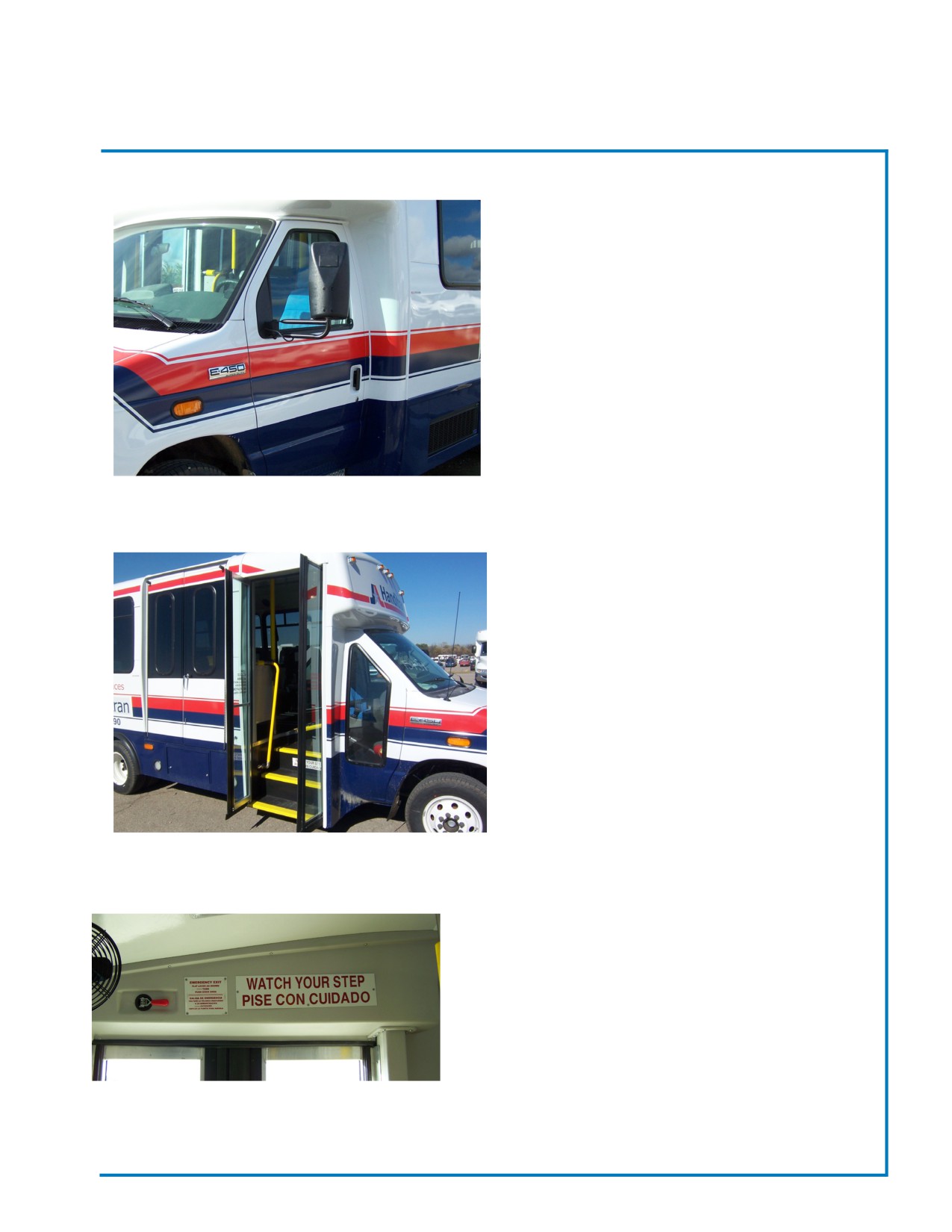
Fig. 2.1 - Cab Doors
The Chassis Cab Doors are a typical automotive style
door with a standard release handle, window crank,
and door locking mechanism. GCA does not modify
the Chassis Cab Door in any way. For additional in-
formation regarding the operation and maintenance of
these doors, consult the chassis owner’s manual.
PASSENGER ENTRY DOOR
The Passenger Entry Door is located on the curb-
sideof the bus and can be opened by an electric
motor. The steel door frame and stepwell are fixture-
welded to form a single unit which offers strength and
durability. Door panels open outward and are mount-
ed in the door fram with pivot pins at both the top and
bottom. Opening, closing, and locking procedures, as
well as door adjustment instructions and maintenance
schedules for your Passenger Entry Door can be
found with the door information specific to your bus
Fig. 2.2 - Passenger Entry Door
that follows in this section.
DOOR ACTUATOR TRIM PANEL
The Door Actuator Trim Panel is located above
thepassenger entry door. This Trim Panel protects the
door linkage, actuator, and door motor (Electric Doors
Only) for manual, pneumatic, and electric doors. To
access the door mechanism, turn knobs, lift slightly
and remove.
Fig. 2.3 - Door Actuator Trim Panel
Revised: October 2007
Page 38
Champion Bus, Inc. Maintenance
SECTION 6
Doors
GENERAL MAINTENANCE
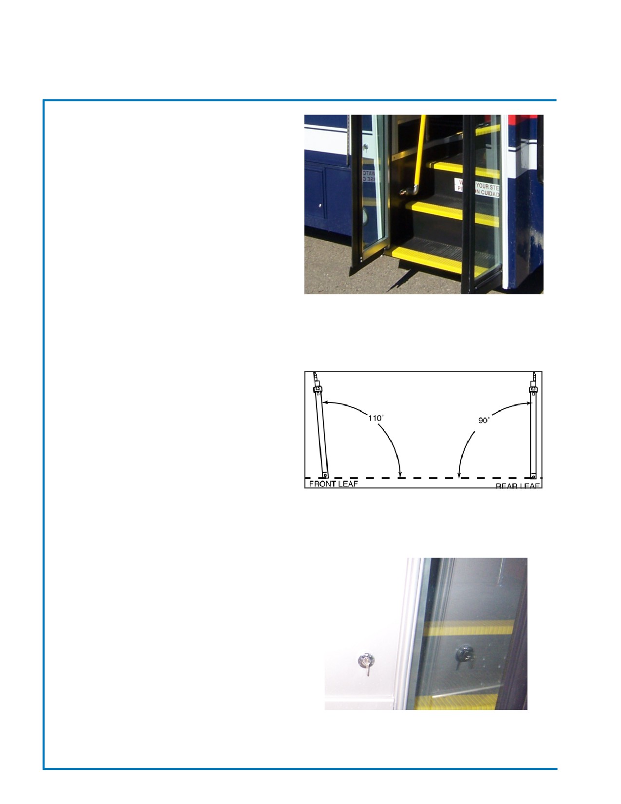
• DOOR SEALS - Inspect door seals every week for
material quality and tight fit. Repair or replace
damaged seals, as necessary. Spray door seal sur-
faces with a light coating of silicone every 12,000
miles or 3 months to keep seals soft and supple. If
doors seals do not close tight and they do not show
excessive wear, adjust the closing mechanism ac-
cording to the diagrams in this manual.
• HINGE & CLOSING MECHANISMS - Lubricate
hinges and closing mechanisms monthly with one
Fig. 2.4 - Door Seals
(1) or two (2) drops of light machine oil. This helps
prolong the life of hinge pins and closing mechanisms,
prevents corrosion, binding, and squeaks. SAE 5
weight non-detergent motor oil and/or WD-40™ spray
work well for these lube applications. White lithium
grease is also recommended to lubricate the closing
mechanism linkage. For all applications, avoid overlu-
brication as excess oil or grease tend to collect
dirt and soil clothing.
• DOOR ALIGNMENT - Check door alignment
weekly. Over time, worn door pins and loose
fasteners may allow door hinges to shift. Tighten
loose nuts, replace worn parts, and/or realign door
Fig. 2.5 - Door Alignment Check
panels as necessary. Door diagrams, indication points
of adjustment for your door, follow in this section.
• KEY LOCKS & SWITCHES - Lubricate key locks
with a lubricant that is recommended for door locks.
DO NOT use lightweight or detergent-type lubricants
as they may wash the original graphite lubricants out
of the lock tumblers, harming the function of the key
locks.
• WINDOWS - Windows on bus doors should be
cleaned on a regular basis to assure visibility and
passenger safety. Interior and exterior door glass
surfaces should be cleaned daily using a household
Fig. 2.6 - Outside Door Switch
ammonia solution or other glass cleaner and a soft
nonabrasive cloth, sponge, or chamois to remove any
dirt or film.
Revised: October 2007
Page 39
Champion Bus, Inc. Maintenance
SECTION 6
Doors
ENTRY DOOR LEAF ADJUSTMENTS.
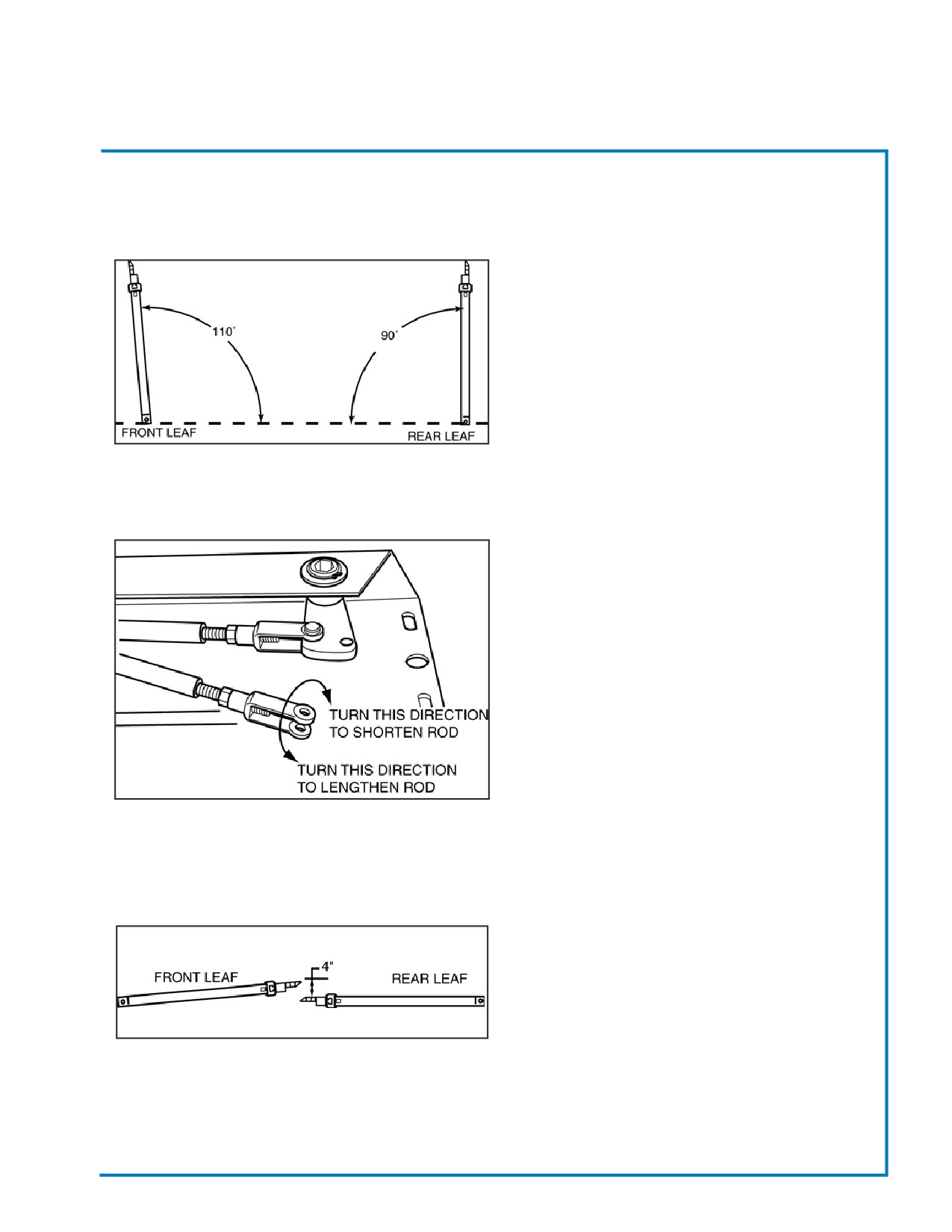
1. Optimum Door Leaf Operation:
a. Open Door’s Rear Leaf so that it “Opens”
90° to the door header.
b. When you “OPEN” the Door’s Rear Leaf
the Door’s Front Leaf will open
somewhere between 5° to 10° past 90°.
Fig. 2.7 - Door Alignment Check
ADJUST
1. Adjust Door’s Control Rod’s Length:
a. Remove Cotter Pin and Clevis Pin from
Control Rod’s “Still” end.
b. To Adjust Control Rod’s length…loosen
Yoke’s Locknut and turn Yoke“Clockwise” to
shorten or “Counterclockwise” to lengthen
the Rod.
c. It is recommended that you only turn the
Yoke 2-complete revolutions and check
the door operation each time you make
and adjustment.
Fig. 2.8 - Door Adjustment Rod
d. After you achieved Door Leaf Optimal
Operation as mentioned in step 1b, tighten
locknut to secure adjustment.
2. Check for Proper Adjustment:
a. Close Door’s Rear Leaf until it bottoms
out at the door header, the Door’s Front
Leaf Edge Seal should be 4” away from
the Rear Leaf’s Edge Seal (Rubber).
b. If everything falls within these specs.
Fig. 2.9 - Proper Adjustment
Then Mechanical Adjustment has been
achieved.
Revised: October 2007
Page 40
Champion Bus, Inc. Maintenance
SECTION 6
Doors
PARATRANSIT DOOR
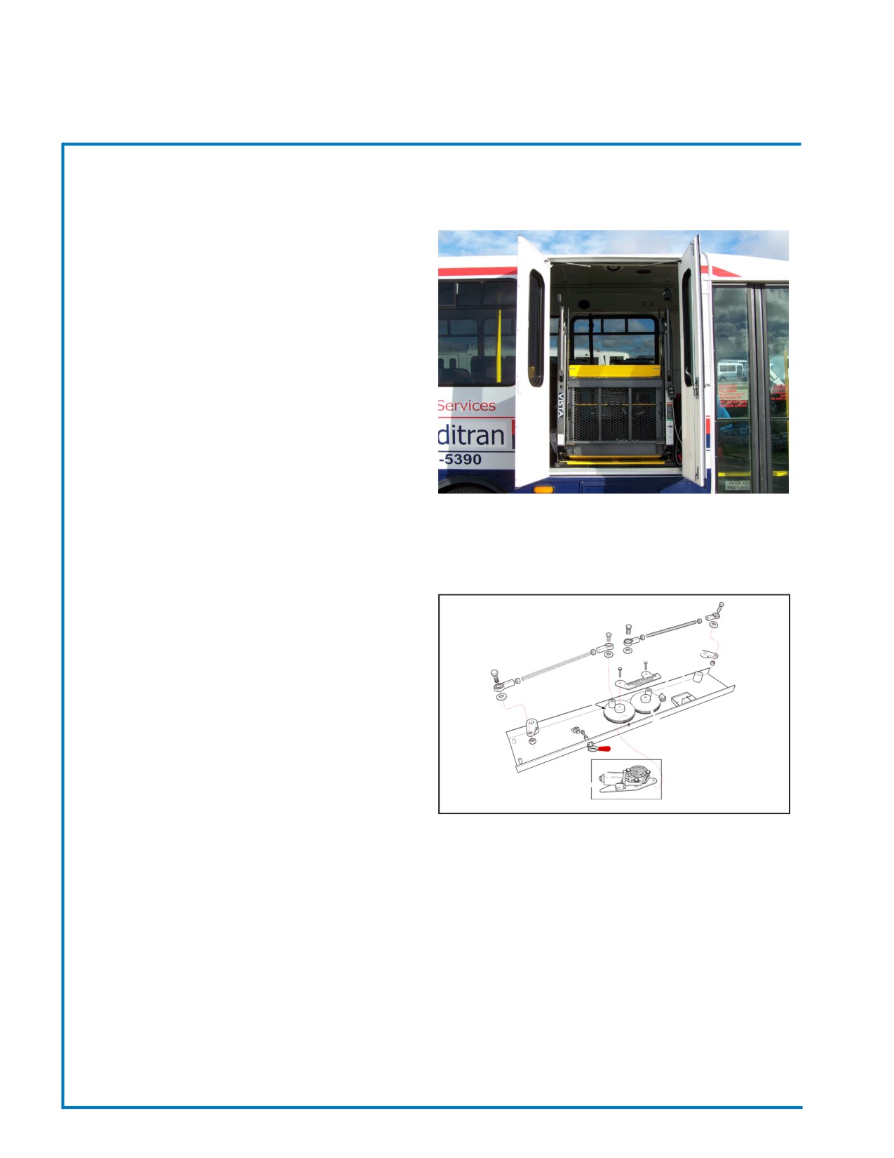
The Bi-Fold Paratransit Door consists of two panels
fastened to the bus with upper and lower pivots. Each
door panel has its own handle that rotates locking
rods, away from the door jamb allowing the door to
open “outward”. Typically, two bi-fold door leaf assem-
blies are used in a door portal, one each opening to
the right and left sides, respectively. (Refer to Fig. 10)
The Bi-Fold Door panels may also have Gas Struts or
“dampeners” installed to restrict the free movement of
the door leafs after opening.
Fig. 2.10 - Paratransit Door
ELECTRIC PASSENGER ENTRY DOOR
The electric passenger entry door consists of two door
panels that are opened by an electric switch mounted
on the drivers control console. The rack and pinion
drive mechanism, located at the top of the door, al-
lows both door panels to be moved when the switch is
activated.
To operate the Electric Entry Door, the vehicle must
be in “PARK”. The door can then be opened and
closed by using the toggle or rocker switch (depend-
ing on the option) located driver’s control panel.
Fig. 2.11 - Electric Door Assembly
To “OPEN” the entry door, hold the toggle or rocker
switch in the “OPEN” position until the door panels
open to a full travel.
To “CLOSE”, hold the toggle or rocker switch in the
“CLOSED” position until the door panels close tightly.
For passenger safety, ensure that exiting passengers
have moved away from the bus and/or all boarding
passengers are seated before closing the entry door
and taking the bus out of “PARK”.
Revised: October 2007
Page 41
Champion Bus, Inc. Maintenance
Notes:
Section 7 - Windows
GENERAL INFORMATION & MAINTENANCE
44
EGRESS (EMERGENCY EXIT) WINDOWS
44
SLIDING WINDOW
45
PLUG WINDOW
45
SECTION 7
Windows
GENERAL INFORMATION & MAINTENANCE
Safety glass is used for all windows in this bus. Windows in the passenger area also have tint to reduce sun
glare and heat. When windows are installed in the passenger area of the bus, the window frames are sealed
to the bus body by a compressed, adhesive-backed rubber seal. This seal forms a water and air tight seal
between the inside of the bus to the outside of the bus.
• Windows should be cleaned and maintained on a regular basis to assure visibility and passenger
safety. Interior and exterior glass surfaces should be cleaned daily using a household ammonia
solution or other glass cleaner and a soft, nonabrasive cloth, sponge or chamois to remove any dirt or
film.
• Latches and seals around sliding or hinged panels should be checked and windows should be
opened and closed daily as the windows are cleaned. Special attention should be given to egress
(emergency exit) windows to assure that release handles are in the fully locked position. Apply silicone
lubricant to release handles on egress windows as needed. If release handles become difficult to
operate, consult your GCA Dealer for recommended service.
• If leaks occur, apply ManusBond window weld, or a silicone-based sealant around window frames
and/or glass. For best results, clean surfaces thoroughly before application.
• Replacement windows and other window parts may be obtained through your GCA Dealer.
EGRESS (EMERGENCY EXIT) WINDOWS
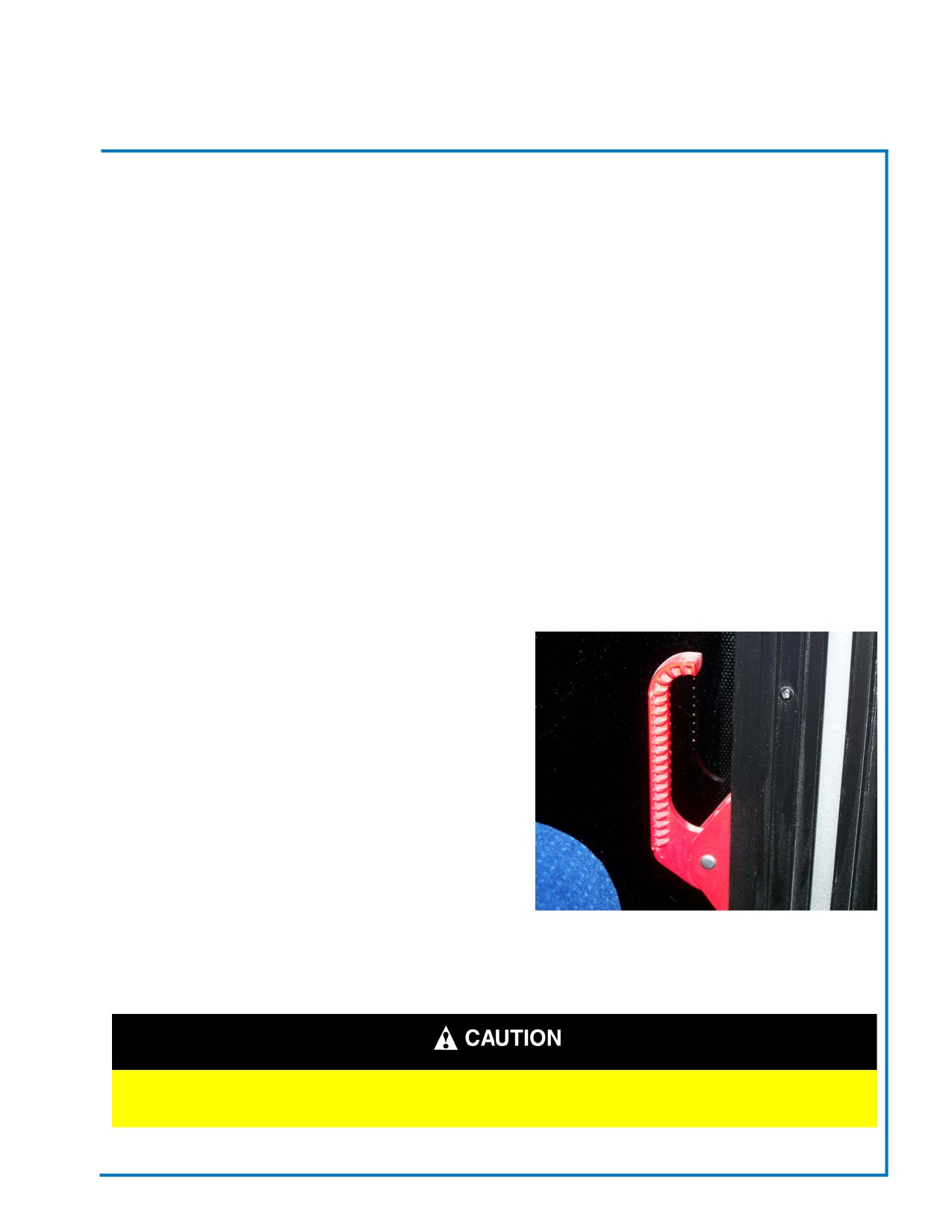
GCA Buses are equipped with egress, or emergency
exit,windows in the passenger area. Egress windows are
easily identified by window decals and/or option red lights
above the windows and two-release handles
either along the sides or at the bottom of the window
frame.
To operate these windows, rotate the red release
handles away from the window frame and push out on
the window. The frame has a fixed hinge at the top that
allows the egress window to swing out for emergency
exit and swing back to close. Operating instruction are
provided on window decals.
• Egress window release handles should be
checked daily to assure they are in the fully
locked position.
Figure 7.1 - Egress Handle
Apply silicone lubricant to the release handles if
they become difficult to operate.
DO NOT OPEN EGRESS WINDOWS WHILE THE BUS IS IN MOTION!
PERSONAL INJURY OR BUS DAMAGE MAY RESULT.
Revised: October 2007
Page 44
Champion Bus, Inc. Maintenance
SECTION 7
Windows
SLIDING WINDOWS
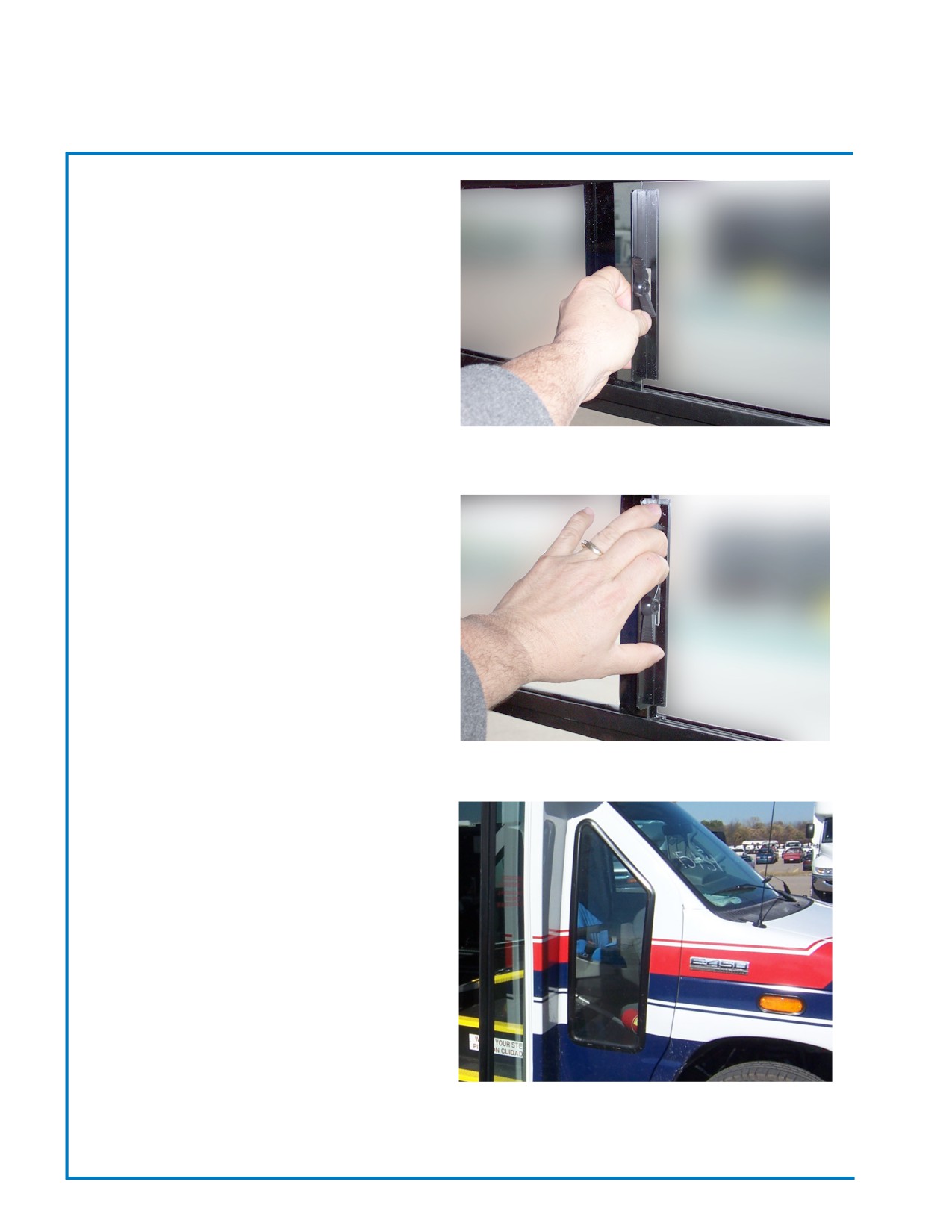
Most passenger windows can be “OPENED” for
ventilation. This sliding window will be located either
at the top or bottom of the window frame.
To “OPEN”, push “DOWN” on the lock release latch
(located at the center of the sliding window frame) and
pull the sliding window pane to the side. “CLOSE” the
window gently - by pushing the sliding window pane
to the side until closed and lock into position by push
“UP” on the lock release.
• Clean and apply silicone lubricate to the
window groove every two (2) months, or as
Fig. 7.2 - “OPEN” Slider Window
needed, to help keep sliding window’s action
smooth.
PLUG WINDOW
The Plug Window is located in front of the Entry Door
on the curbside of the bus, Plug Windows allow the
driver, while seated in the driver’s seat, to observe the
curb and passengers who may be standing in front of
the entry door.
Plug Windows are installed using an adhesive sealant
that holds the window in place and forms a water-
resistant and air resistant barrier around the window.
Fig. 7.3 - “LOCK” Slider Window
A rubber trim panels around the window helps seal
the window to the bus body.
• Plug windows should be cleaned every day,
as dirt and grime from daily driving may collect
on the window and block visibility.
Fig. 7.4 - Plug Window
Revised: October 2007
Page 45
Champion Bus, Inc. Maintenance
Notes:
Section 8 - Electrical & Lighting
GENERAL INFORMATION
48
BUS REVERSING AID
48
POWER DISTRIBUTION CENTER (FUSE PANEL)
48
AUTOMATIC-RESET CIRCUIT BREAKERS
48
ELECTRICAL SYSTEM REPAIR
49
EXTERIOR LIGHTING
49
HEADLIGHTS
50
LED SIDE MARKER LIGHTS
50
INTERIOR LIGHTING
50
CBI ELECTRICAL MANUAL
WIRE STAMPING & CODE
1-6
.ONNECTOR LOCATIONS
7-10
.ROUBLESHOOTING
11
OVERALL WIRING SCHEMATIC
12
LIFT DOOR HARNESS
13
.IFT DOOR HARNESS - 2
14
.ESTINATION SIGN HARNESS
15
.UXILARY RADIO HARNESS
16
.PEAKER HARNESS -EXTERNAL
17
Section 8 - Electrical & Lighting
CBI ELECTRICAL MANUAL (CONT.)
CHASSIS TIE-IN HARNESS
18
.OME LIGHT HARNESS
19
.EADING LIGHT HARNESS
20
CONSOLE HARNESS
21
LEFT OVERHEAD HARNESS (LENGTH)
22
.-WAY CONNECTOR INFORMATION
23
.-WAY CONNECTOR INFORMATION
23-24
SECTION 8
Electrical & Lighting
GENERAL INFORMATION
This section contains information on portions of the electrical system and lighting that are unique to the GCA
bus. All bus circuits are connected to the chassis 12-Volt Negative Ground Electrical System. The ignition switch
activates most of the bus circuits.
Information on the chassis circuits and wiring, including headlights, turn signals, dashboard lighting, and fuse
panel may be found in the manuals provided by the chassis manufacturer. In addition, the chassis owner’s
manual includes a listing of bulbs and fuses used for chassis related components. Chassis service literature,
including wiring diagrams and electrical troubleshooting manuals, are available from your local Ford or Chevy
dealer or by using the order forms in the chassis owner’s manual.
Bus Reversing Aid (if applicable)
1. USE CAUTION WHEN TESTING. A trained driver with assistance in a secured area is recommended.
2. Engage reverse gear. The Bus Reversing Aid will activate automatically.
3. Drive backward slowly until voice distance indicator is heard.
4. Keep sensors clean of dirt and other debris.
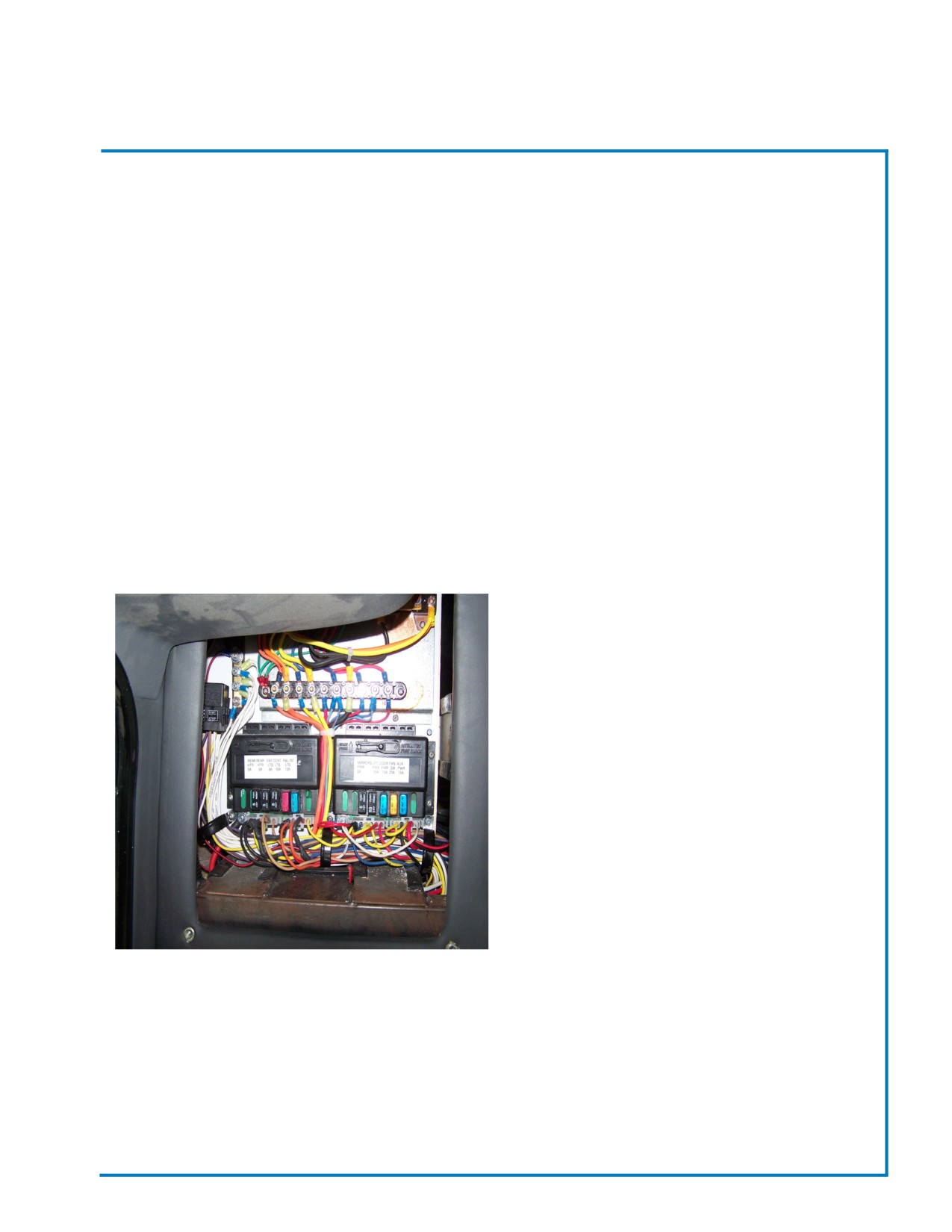
POWER DISTRIBUTION CENTER (FUSE PANEL)
The Power Distribution Center (Fuse Panel) provides
power to different electrical systems within the bus.
Wiring diagrams or schematics of the Power Distribution
Center (Fuse Panel) clearly identify the circuits and
are shipped with of your vehicles. All wiring for the
body conversion (except wires less than 12 inches in
length) is color-coded and stamped every 12 inches
with circuit numbers and abbreviated codes, making
circuit tracing easier. Most wiring is bundled into “wiring
harnesses” that are routed from the Power Distribution
Center (Fuse Panel) into the parcel racks. The wires
usually are routed the shortest distance to the area
where power is being supplied. Removable interior
trim panels protect and allow access to the wiring that
is routed throughout the bus.
AUTOMATIC-RESET CIRCUIT BREAKERS
Automatic-reset Circuit Breakers, located in the Power Distribution Center (Fuse Panel), are an optional feature
that protect heavy power demand circuits. A power draw overload will cause a brief interruption in electrical
power before the circuit breaker automatically resets itself.
• If a breaker is frequently interrupted or if the circuit breaker “cycles”, look for a “short” or other problem
before returning the bus to service.
Revised: October 2007
Page 48
Champion Bus, Inc. Maintenance

SECTION 8
Electrical & Lighting
ELECTRICAL SYSTEM REPAIR
Electrical system troubleshooting should begin with the Fuse Panel. Wiring diagrams included with the bus
indicate wiring colors, the stamped circuit numbers, and the circuit schematics.
• Wiring repairs should only be performed by a qualified technicians.
• Consult your local GCA dealer before performing any electrical, or other repairs. Unauthorized repairs may
void bus warranties.
• Use replacement fuses of the specified type and amperage rating only. Using other fuses may cause damage
to electrical systems and increase the risk of electrical fires.
• When repairing circuits, be sure that wiring is protected from damage.
• Use ring terminals, spade connectors, or butt connectors as a last resort. Solder all connections and heatshrink
to insulate whenever possible.
• Place repaired wire back into loom and secure with plastic wire-ties. Avoid routing wire harness close to major
heat sources or sharp edges.
• The cigarette lighter receptacle may be used as a power source for accessories.
ELECTRICAL POWER IS ALWAYS “LIVE” IN THE POWER DISTRIBUTION CENTER (FUSE
PANEL). USE CAUTION WHEN PERFORMING REPAIRS. DO NOT OPERATE THE VEHICLE
WITH THE ACCESS DOOR OPENED. DOING SO MAY ENDANGER PASSENGERS AND
COULD SHORT CIRCUIT THE VEHICLE’S ELECTRICAL SYSTEM.
EXTERIOR LIGHTING
LED Exterior Lighting is designed to assure the visibility of the bus to other drivers and pedestrians. Exterior
lighting consists of front and rear clearance lights, rear tail, brake, backup, and stop lights, license plate light,
side marker lights, and headlights.
Wiring Harnesses for exterior lighting originate in the Power Distribution Center (Fuse Panel) and are routed
throughout the bus. Most wiring can be accessed by removing the interior trim panels.
Revised: October 2007
Page 49
Champion Bus, Inc. Maintenance
SECTION 8
Electrical & Lighting
HEADLIGHTS
The vehicle’s Headlight Control Knob is located on the dash. Headlights should be turned “ON” when
driving at night, or whenever weather or safety conditions require that headlights be “ON”.
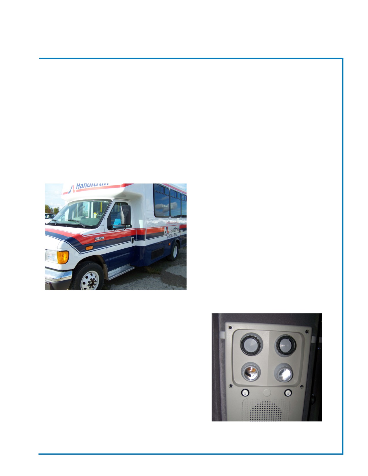
LED MARKER LIGHTS
The incandescent Marker Light consists of a circular red lens on a circular base. One light is located on either
side of the rear of the bus. The incandescent Marker Lights indicate the exterior side wall of the bus and provide
noticeability at night and in less than desirable driving conditions.
Standard Front Marker Lights are a component of the body lighting system. These amber colored lights
are located at he front corners of the bus and are activated when the headlights are turned “ON”. These lights
are combined with the parking lights and also flash “ON/OFF” when turn signals are activated.
• Marker Lights should be inspected daily for proper
operation.
• To replace burned-out Marker Lights, pry out from
rubber grommet.
• Disconnect wire harness connector from Marker Light
and discard light.
• Connect new Marker Light to wire harness
connector.
• Apply a bead of silicone around perimeter of Marker
Light, align holes in light to holes in bus body. Push in
until secure.
INTERIOR LIGHTING
Interior Lighting consists of Incandescent Lights that
are attached to the ceiling. There are also LED Lights
attached to the parcel racks. These lights provide an
even cabin illumination for passenger and driver
safety.
• Interior Lighting should be inspected daily for
proper operation.
Revised: October 2007
Page 50
Champion Bus, Inc. Maintenance
Champion
Electrical Manual
2008
Table of Contents
1
Table of Contents
2-6
Wire Stamping and Coding
7-10
Connector Locations
11
Troubleshooting
1
Wire Stamping and Coding
Color Codes
T
Tan
I
Pink
Y
Yellow
O
Orange
E
Grey
W
White
K
Black
B
Blue
R
Red
P
Purple
G
Green
N
Brown
2
Wire Stamping and Coding
STAMPING CODES
AC
Air Conditioner
CH
Chime
FD
Field
LO
Low
PW
Power
TA
Tail
AJ
Ajar
CB
Circuit Breaker
FO
Fluorescent
LT
Light
PA
Public Address
TH
Throttle
AL
Alarm
CI
Cigarette
FT
Front
LU
Laminator
PR
Pressure
TI
Timer
AS
Accessory
DF
Defrost
FE
Fuel
LV
Lavatory
PU
Pump
TO
Toilet
AT
Actuator
DK
Docking
GR
Ground
LTR
Lighter
RE
Rear
TM
Transmission
AR
Air
DM
Dome
GA
Gauge
MC
Micro
RA
Radio
TN
Turn
AX
Auxiliary
DA
Dash
GE
Generator
MD
Medium
RD
Reading
TP
Tap
AU
Auto
DN
Destination
GU
Guard
MK
Marker
RM
Remote
TV
Television
ALT
Alternator
DR
Door
HD
Head
MR
Mirror
RL
Relay
TG
Tag
AM
Amber
DS
Disconnect
HI
High
MS
Master
RQ
Request
TX
Tag Axel
BK
Brake
DV
Driver
HL
Hold
MT
Mid Turn
RS
Reset
TE
Temperature
BU
Back-up
DE
Deceleration
HT
Heat
MY
Memory
RT
Right
TL
Telma
BX
Box
EG
Energize
HO
Hood
ME
Meter
RG
Regulator
VL
Valve
BZ
Buzzer
EN
Entry
HR
Hour
MA
Main
SA
Safety
VR
Vortec
BR
Braun
EX
Exit
ID
Idle
MO
Motor
SG
Signal
VC
Videocassette Rec.
BT
Battery
ENG
Engine
IG
Ignition
NU
Neutral
SL
Solenoid
VT
Volt
CD
Cord
ED
Edge
IL
Interlock
OF
Off
SN
Sign
VM
Vacuum
CG
Cargo
FA
Fare
IN
Interlock
OH
Overhead
SP
Spare
WC
Wheelchair
CN
Control
FH
Fresh
IM
Illumination
OP
Open
SR
Sensor
WN
Window
CL
Close
FU
Full
IS
Isolation
OI
Oil
ST
Starter
WP
Wiper
CC
Circuit
FN
Fan
IT
Interrupt
OR
Override
SW
Switch
WA
Water
CS
Constant
FR
Frost
KN
Kneeler
PG
Plug
SH
Shot
WR
Warning
CT
Clutch
FS
Fast
LF
Left
PK
Park
SO
Stop
WE
Well
CR
Courtesy
FI
Fire
LG
Luggage
PL
Pull
SE
step
CO
Cut out
FL
Flasher
LI
Lift
PN
Panel
SV
Sensitive
3
CM
Compressor
FG
Fog
LM
Limit
PS
Passenger
STA
Stator

Wire Stamping and Coding
WHITE
PINK
BLACK
01
W
DRIVER FAN LOW
01
I
DOOR MOTOR
03
K
SINGLE CONDENSER
02
W
DRIVER FAN HIGH
04
I
RIGHT READING LIGHT
04
K
HOOD LIGHT
03
W
DUAL CONDENSOR
07
I
EXIT LIGHT
07
K
IN GEAR
04
W
MOTOR GROUND
08
I
WHEELCHAIR SWITCH
08
K
DOME LIGHT
05
W
OIL
08A
I
WHEELCHAIR SWITCH
09
K
STOP REQUEST
06
W
12V STARTER
09
I
ENTRY DOOR
09A
K
STOP REQUEST
07
W
TEMP
11
I
WHEELCHAIR ALARM
11
K
TAG AXLE VACUUM
09
W
DOOR CLOSE
12
I
BRAUN INTERLOCK SL
12
K
RAMP STOW
11
W
STOP REQUEST
16
I
ALTERNATOR IGNITION
20
K
DEFROST POWER
13
W
DRIVER LIGHT
23
I
PULL CORD
18
W
BUZZER ALARM
23A
I
PULL CORD
25
W
AIR CONDITIONER
24
I
WINDOW AJAR
30
W
ENGINE KILL
BLUE
31
W
ENGINE KILL
GRAY
02
B
COMPRESSION AMPLIFIER
BROWN
01
E
DASH LIGHT
03
B
SINGLE COMPRESSO
02
N
DOOR MOTOR
03
E
LUGGAGE DOOR AJAR
04
B
READING LIGHT
06
N
LOW AIR
10
E
WHEELCHAIR DOOR SL
08
B
COURTESY LIGHT
07
N
MAP LIGHT
14
E
DESTINATION SIGN
09
B
BRAKE LIGHT
09
N
MARKER LIGHT
14A
E
HOOD LIGHT
10
B
WHEELCHAIR DOOR
11
N
12V RUN
15
E
LUGGAGE LIGHT
12
B
STOP REQUEST
24
N
FARE BOX
29
E
DOCKING LIGHT
15
B
TRANSMISSION HOLD
4
Wire Stamping and Coding
RED
YELLOW
ORANGE
PURPLE
02
R
DOME LIGHT POWER
01
Y
12V BATTERY
04
O
HEATER #2 HIGH
02
P
AUXILIARY POWER
04
R
HEATER #2 POWER
04
Y
HEATER #2 MEDIUM
05
O
HEATER VALVE
03
P
DUAL COMPRESSOR
05
R
LEFT READING LIGHT
05
Y
SIGH MOTOR
06
O
TAG AXLE POWER
04
P
HEATER #2 LOW
06
R
VOLT METER
07
Y
HEATER #1 MEDIUM
07
O
HEATER #1 HIGH
06
P
PUBLIC ADDRESS POWER
07
R
HEATER #1 POWER
09
Y
DOOR OPEN
08
O
TM SWITCH
07
P
HEATER #1 LOW
08
R
RIGHT READING LIGHT
10
Y
OEM COURTESY LIGHT
09
O
STEP LIGHT
09
P
IGNITION SIGNAL
09
R
DOOR POWER
18
Y
LEFT TURN SIGNAL
10
O
WHEELCHAIR DOOR
10
P
IGNITION INTERLOCK POWER
10
R
AUXILIARY DOOR POWER
19
Y
7" LIGHT
10A
O
AJAR LIGHT
12
P
PASSENGER SIGNAL
11
R
RADIO IGNITION
19A
Y
FRONT 7" LIGHT
12
O
PULL CORD
13
P
DRIVER DOME LIGHT
12
R
RADIO BATTERY
20
Y
FRONT FO
12A
O
PULL CORD
15
P
PARK BRAKE
13
R
DESTINATION SIGN
21
Y
MEDIUM FO
13
O
WHEELCHAIR POWER
18
P
7" LIGHT
15
R
TM SOLENOID POWER
22
Y
REAR FO
16
O
VORTEC SL SIGNAL
19
P
IGNITION SIGNAL
18
R
RIGHT TURN SIGNAL
23
Y
WINDOW AJAR
18
O
7" LIGHT
20
P
IGNITION SIGNAL
23
R
PASSENGER PULL CORD
24
Y
WINDOW AJAR
18A
O
REAR 7" LIGHT
21
P
DRIVER FAN
23A
R
PASSENGER PULL CORD
25
Y
BUZZER GROUND
21
O
IGNITION LOW
22
P
DRIVER FAN
24
R
WINDOW AJAR
26
Y
IGNITION LOW
22
O
IGNITION LOW
29
P
TEMPERATURE ALARM
25
R
WHEELCHAIR PULL CORD
27
Y
IGNITION LOW
30
P
OIL ALARM
25A
R
WHEELCHAIR PULL CORD
30
Y
STARTER DISABLE
30
R
RAMP DEPLOY
31
Y
STARTER DISABLE
5
Wire Stamping and Coding
TAN
Green
03
T
LUGGAGE LIGHT
No Stamping Required.
04
T
LUGGAGE LIGHT SWITCH
May be coded with the letter "G“ and a
05
T
RUN ACCESSORIES
suffix of manufacturers specifications.
07
T
PASSENGER SIGNAL
08
T
LIFT LIGHT
15
T
TM ENTRY
25
T
IL ALARM SIGNAL
SPEAKERS (TAGS)
27
T
TELMA
28
P
RT REAR SPEAKER
STRIPED
28
P/K
RT REAR SPEAKER
02
W/B
DRIVER THERMOSTAT
28
G
LEFT REAR SPEAKER
03
K/W
AC DEM THERMOSTAT
28
G/K
LEFT REAR SPEAKER
03
E/W
DUAL AC OEM THERMOSTAT
28
E
RIGHT FRONT SPEAKER
03
O/W
A/C FAN HI SPEED
28
E/K
RIGHT FRONT SPEAKER
03
R/W
A/C FAN LOW SPEED
28
W
LEFT FRONT SPEAKER
03
W/B
A/C FAN POWER
28
W/K
LEFT FRONT SPEAKER
03
Y/W
A/C FAN MEDIUM SPEED
SPK5C
EXTERNAL SPEAKER
12
I
BRAUN INTERLOCK SL
SPK5T
EXTERNAL SPEAKER
16
I
ALTERNATOR IGNITION
SPK6C
RE PUBLIC ADDRESS SPEAKER
23
I
PULL CORD
SPK6T
RE PUBLIC ADDRESS SPEAKER
23A
I
PULL CORD
SPK7C
FT PUBLIC ADDRESS SPEAKER
24
I
WINDOW AJAR
SPK7T
FT PUBLIC ADDRESS SPEAKER
6
Connector Locations
Connector
Function
Harness
Location
C 100
Console
Front Floor
Right side of the engine access cover
C 100A
Console
Front Floor
Right side of the engine access cover
C 100B
Console
Front Floor
Right side of the engine access cover
C 100C
Console
Front Floor
Right side of the engine access cover
C 101
Entry Feed
Front Floor
Behind electrical center panel
C 102
Front Cap
Front Floor
Behind electrical center panel
C 103
RH O/H
Front Floor
Behind electrical center panel
C 104
RH O/H
Front Floor
Behind electrical center panel
C 105
LH Dome Lights
Left Overhead
Above entry door behind cover
C 106
Rear Cap
RH O/H
Passenger side rear corner
C 107
Heater 1
RH O/H
Behind electrical center panel
C 108
Heater 2
Front Floor
Behind electrical center panel
C 109
LH Interior Lights
RH O/H
Above entry door behind cover
C 110
RH Interior Lights
RH O/H
Above entry door behind cover
C 111
Rear Cap
RH O/H
Passenger side rear corner
C 112
Tag Axle
Rear Cap
Driver side rear corner
C 113
Electric Door Motor
Entry Door
Above entry door behind cover
C
114
Floor Courtesy Lights
RH O/H
Above entry door behind cover
C
115
Restroom
Rear Cap
Driver side rear corner
C
116
Rmt. Entry Door
Entry Feed
Above entry door behind cover
C
117
RH/LH Reading Lights
Int. Lt.
Above entry door behind cover
C
118
RH/LH Dome Lights
Int. Lt.
Above entry door behind cover
C
119
I/P
Rear Evap AE
Behind driver switch panel
C
120
Engine Alarm
Front Floor & I/P AE
Behind driver switch panel
C
121
Top Relay Row
Front Cap
On main electrical panel
7
Connector Locations
Connector
Function
Harness
Location
C 122
Entry Door
Front Floor AEN
Above entry door behind cover
C 123
I/P to RH O/H
I/P AE
Behind driver switch panel
C 124
Left Front Speaker
Front Cap
Driver side wing panel
C125
Trans Interlock
Front Floor (Not AT/AL)
not used
C126
Trans Interlock
Front Floor
not used
C127
Fuse Block
Front Cap
above driver wing pad
C128
Fuse Block
Front Cap
above driver wing pad
C129
Right Front Speaker
Front Cap
right side top of front cap
C130
Sensitive Edge
Entry Door
above entry door behind cover
C131
Park Brake/Low Air
Front Floor / I/P AE
center dash behind radio
C132
Rear Door Ajar
Front Floor
center rear of rear cap
C133
Window Ajar
Front Floor / I/P AE
behind electrical center panel
C134
Pass Pull Cord
Front Floor / I/P AE
behind electrical center panel
C135
WC Pull Cord
Front Floor / I/P AE
behind electrical center panel
C136
EN DR AR VL
not used
C137
Radio
Front Floor
center dash behind radio
C138
LH Exit Lights
Left Overhead
driver side rear corner
C139
Ramp
Entry Feed - AA
behind electrical center panel
C140
RH Brake & Tail
Rear Cap
passenger side rear middle
C141
RH Mid Turn/Marker
Rear Cap
passenger side rear middle
C142
RH Turn
Rear Cap
passenger side rear middle
C143
RH Brake & Tail
Rear Cap
passenger side rear middle
C144
RH Back-up
Rear Cap
passenger side rear middle
C145
CTR Brake
Rear Cap
top center rear
8
C146
LH Brake & Tail
Rear Cap
passenger side left middle
Connector Locations
Connector
Function
Harness
Location
C147
LH Mid Turn/Marker
Rear Cap
passenger side left middle
C148
LH Turn
Rear Cap
passenger side left middle
C149
LH Brake & Tail
Rear Cap
passenger side left middle
C150
LH Back-up
Rear Cap
passenger side left middle
C151
RH Pwr.
Rear Cap
not used
C152
LH Pwr.
Rear Cap
not used
C153
Tag Light
Rear Cap
driver side bottom rear corner
C154
RH Dome Lights
Front Cap
above entry door behind cover
C155
Rear Brake
Front Floor
behind electrical center panel
C156
Engine & STR Kill
Front Floor
behind electrical center panel
C157
RH Exit Lights
Front Cap
above entry door behind cover
C158
Right Rear Speaker
Rear Cap
passenger side rear corner
C159
Left Rear Speaker
Rear Cap
driver side rear corner
C160
Tow Plug
Rear Cap
driver side bottom rear corner
C161
Ford Connector
Rear Cap
driver side bottom rear corner
C162
Entry Door
Entry Feed
above entry door behind cover
C163
Lift Door
Entry Feed
above entry door behind cover
C164
I/P
Entry Feed AE
behind driver switch panel
C165
Step Well Light
Entry Feed
below entry door sides
C166
Tag Light
Rear Cap
driver side bottom rear corner
C167
Engine & STR Kill
Front Floor
behind electrical center panel
C168
Farebox
Front Floor
behind electrical center panel
C169
Reverse Alarm
Rear Cap
driver side bottom rear corner
C170
Rear Door Switch
Rear Cap
Center top of rear cap
C171
Grounds
Rear Cap
driver side bottom rear corner
9

Connector Locations
Connector
Function
Harness
Location
C172
RH Rear 7" Light
Rear Cap
passenger side top rear corner
C173
LH Rear 7" Light
Rear Cap
driver side top rear corner
C174
Grounds
Front Cap
above entry door behind cover
C175
RH Pass Pull Cord
Rear Cap
passenger side rear corner
C176
LH Pass Pull Cord
Rear Cap
driver side rear corner
C178
PA/Radio
Front Floor
behind electrical center panel
C180
RH WC Pull Cord
Rear Cap
passenger side rear corner
C181
LH WC Pull Cord
Rear Cap
driver side rear corner
C188
Ign. Sol
Front Floor
behind electrical center panel
C189
Rear WDO Exit Light
Rear Cap
Center top of rear cap
C190
Marker Light
Front & Rear Caps
top of rear cap
C191
RH Front 7" Light
Front Cap
passenger side top front corner
C192
LH Front 7" Light
Front Cap
driver side top front corner
C194
Dest. Sign
Front Cap
driver side top front corner
C195
Stop Reg. Sign
Front Cap
driver side top front corner
C196
RH Window Ajar
Rear Cap
passenger side rear corner
C197
I/P
Front Cap AE
behind electrical center panel
C198
LH Window Ajar
Rear Cap
driver side rear corner
C199
Rear Window Ajar
Rear Cap
Center top of rear cap
C200
Rear Luggage Light
Rear Cap
Center top of rear cap
10
Troubleshooting
1.
RED LED is on if the item is “in use” and the fuse is blown.
2.
YELLOW LED is on it the “switch” is activated.
3.
GREEN LED means the relay is fine.
To Troubleshoot the board:
•
Make sure you have the activation ground or power to the item in question.
•
If it is missing then the problem is in the wiring and not the power center.
•
If the inputs are the and the output is missing, disconnect the output connector.
•
Check for power or ground on the output (whichever is required).
•
If it exists then the problem is not the power center.
11
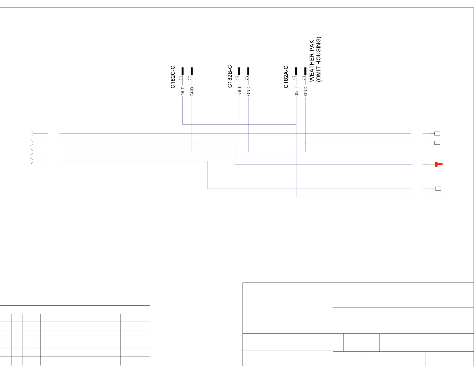
C163-C
L907
1/4
08A I
08A I
2/4
10 B
GND
3/4
GND
4/4
L908
10 O
10 B
L906
10 O
08 T
TITLE:
PRECISIONWORKS
MANUFACTURING
LIFT DOOR HARNESS, EP3
120 9TH AVE E-4
LONGMONT, CO 80501
REVISIONS
ADDITIONAL INFO:
THIS DRAWING IS THE PROPERTY OF
REV.
BY
DATE
DESCRIPTION
RELEASE #
PRECISIONWORKS MANUFACTURING AND IS
NOT TO BE DUPLICATED OR USED IN ANY
WAY DETRIMENTAL TO THEIR BEST INTEREST.
SIZE:
RELEASE NO.
DWG NO.
MATERIAL SPEC:
A
00000
0032192-101
MODEL:
SCALE
DATE
SHEET
NTS
5/7/08
1
OF
2
Champion
C182B
C182C
C182A
32"
13'
5'
15'
C163
L908
6"
L906
6"
L907
NOTES:
1. HARNESS IS TO BE LOOMED.
2. ALL WIRES ARE 14 AWG EXCEPT 08 T AND 02 G AT C182 ARE 16 AWG.
TITLE:
PRECISIONWORKS
MANUFACTURING
LIFT DOOR HARNESS, EP3
120 9TH AVE E-4
LONGMONT, CO 80501
REVISIONS
ADDITIONAL INFO:
THIS DRAWING IS THE PROPERTY OF
REV.
BY
DATE
DESCRIPTION
RELEASE #
PRECISIONWORKS MANUFACTURING AND IS
NOT TO BE DUPLICATED OR USED IN ANY
WAY DETRIMENTAL TO THEIR BEST INTEREST.
SIZE:
RELEASE NO.
DWG NO.
MATERIAL SPEC:
A
00000
0032192-101
MODEL:
SCALE
DATE
SHEET
NTS
5/7/08
2
OF
2
Champion
J9-P
C194-C
1/3
1/3
14 E
2/3
2/3
05 Y
3/3
3/3
GND
NOTES:
1. HARNESS IS TO BE LOOMED.
2. HARNESS IS 5' IN LENGTH.
3. ALL WIRES ARE 14 AWG.
TITLE:
PRECISIONWORKS
MANUFACTURING
DESTINATION SIGN HARNESS, FRONT EP3
120 9TH AVE E-4
LONGMONT, CO 80501
REVISIONS
ADDITIONAL INFO:
THIS DRAWING IS THE PROPERTY OF
REV.
BY
DATE
DESCRIPTION
RELEASE #
PRECISIONWORKS MANUFACTURING AND IS
NOT TO BE DUPLICATED OR USED IN ANY
WAY DETRIMENTAL TO THEIR BEST INTEREST.
SIZE:
RELEASE NO.
DWG NO.
MATERIAL SPEC:
A
00000
0032192-110
MODEL:
SCALE
DATE
SHEET
NTS
5/7/08
1
OF
1
Champion
J10-P
C183-C
1/3
1/3
12 R
2/3
2/3
05 Y
3/3
3/3
GND
NOTES:
1. HARNESS IS TO BE LOOMED.
2. HARNESS IS 5' IN LENGTH.
3. ALL WIRES ARE 14 AWG.
TITLE:
PRECISIONWORKS
MANUFACTURING
AUX RADIO HARNESS, EP3
120 9TH AVE E-4
LONGMONT, CO 80501
REVISIONS
ADDITIONAL INFO:
THIS DRAWING IS THE PROPERTY OF
REV.
BY
DATE
DESCRIPTION
RELEASE #
PRECISIONWORKS MANUFACTURING AND IS
NOT TO BE DUPLICATED OR USED IN ANY
WAY DETRIMENTAL TO THEIR BEST INTEREST.
SIZE:
RELEASE NO.
DWG NO.
MATERIAL SPEC:
A
00000
0032192-115
MODEL:
SCALE
DATE
SHEET
NTS
5/7/08
1
OF
1
Champion

C221-P
1/2
28 P
2/2
28 P/K
NOTES:
1. HARNESS IS TO BE LOOMED.
2. HARNESS IS 8' IN LENGTH.
3. ALL WIRES ARE 18 AWG.
4. UNTERMINATED ENDS ARE BLUNT CUT.
TITLE:
PRECISIONWORKS
MANUFACTURING
SPEAKER HARNESS, EXTERNAL EP3
120 9TH AVE E-4
LONGMONT, CO 80501
REVISIONS
ADDITIONAL INFO:
THIS DRAWING IS THE PROPERTY OF
REV.
BY
DATE
DESCRIPTION
RELEASE #
PRECISIONWORKS MANUFACTURING AND IS
NOT TO BE DUPLICATED OR USED IN ANY
WAY DETRIMENTAL TO THEIR BEST INTEREST.
SIZE:
RELEASE NO.
DWG NO.
MATERIAL SPEC:
A
00000
0032192-116
MODEL:
SCALE
DATE
SHEET
NTS
5/22/08
1
OF
1
Champion
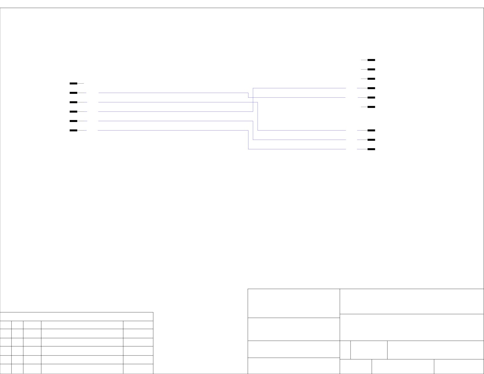
4450M
1/6
NAVISTAR HOUSING:
2/6
PN # 2039312C91
C215-CP
3/6
NAVISTAR TERMINAL:
1/6
PN # 2033912C1
4/6
09 N
2/6
18 W
5/6
18 W
3/6
18 Y
6/6
4/6
09 N
5/6
18 R
4460M
6/6
1/3
09 B
18 Y
NAVISTAR HOUSING:
2/3
18 R
PN # 3553961C1
3/3
NAVISTAR TERMINAL:
09 B
PN # 2033912C1
NOTES:
1. HARNESS IS TO BE LOOMED.
2. HARNESS IS 15' IN LENGTH.
3. ALL WIRES ARE 14 AWG.
TITLE:
PRECISIONWORKS
MANUFACTURING
CHASSIS TIE IN HARNESS
120 9TH AVE E-4
LONGMONT, CO 80501
REVISIONS
ADDITIONAL INFO:
THIS DRAWING IS THE PROPERTY OF
REV.
BY
DATE
DESCRIPTION
RELEASE #
PRECISIONWORKS MANUFACTURING AND IS
NOT TO BE DUPLICATED OR USED IN ANY
NAVISTAR
WAY DETRIMENTAL TO THEIR BEST INTEREST.
SIZE:
RELEASE NO.
DWG NO.
MATERIAL SPEC:
A
0032192-120
MODEL:
SCALE
DATE
SHEET
NTS
1
OF
1
Champion
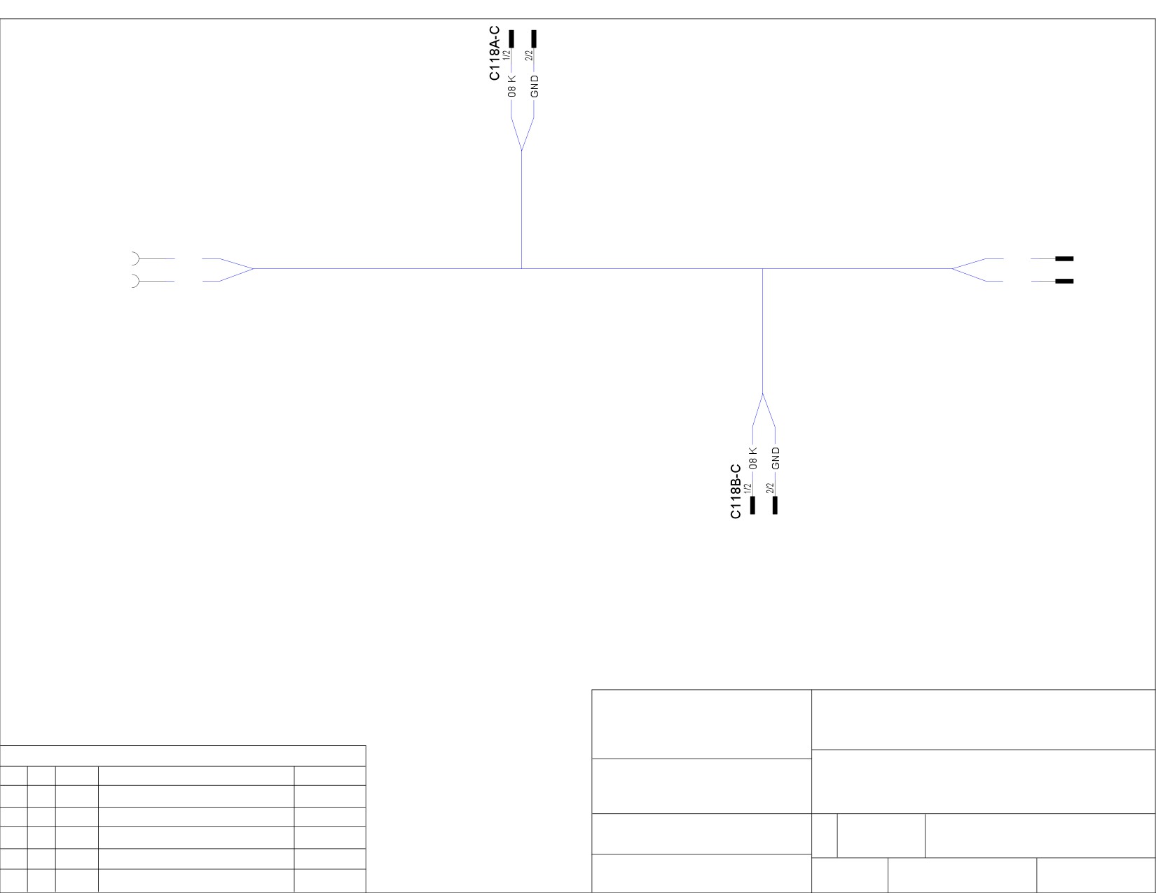
12"
C105-P
C118C-C
1/2
96"
1/2
08 K
72"
108"
08 K
2/2
2/2
GND
GND
12"
NOTE:
1) SEE 0032192 FOR SCHEMATIC.
TITLE:
2) ALL DIMENSIONS ARE SHOWN IN INCHES.
PRECISIONWORKS
MANUFACTURING
DOME LIGHT HARNESS, EP3
120 9TH AVE E-4
LONGMONT, CO 80501
REVISIONS
ADDITIONAL INFO:
THIS DRAWING IS THE PROPERTY OF
REV.
BY
DATE
DESCRIPTION
RELEASE #
PRECISIONWORKS MANUFACTURING AND IS
NOT TO BE DUPLICATED OR USED IN ANY
WAY DETRIMENTAL TO THEIR BEST INTEREST.
SIZE:
RELEASE NO.
DWG NO.
MATERIAL SPEC:
A
00000
0032192-150
MODEL:
SCALE
DATE
SHEET
NTS
12/4/07
1
OF
1
Champion
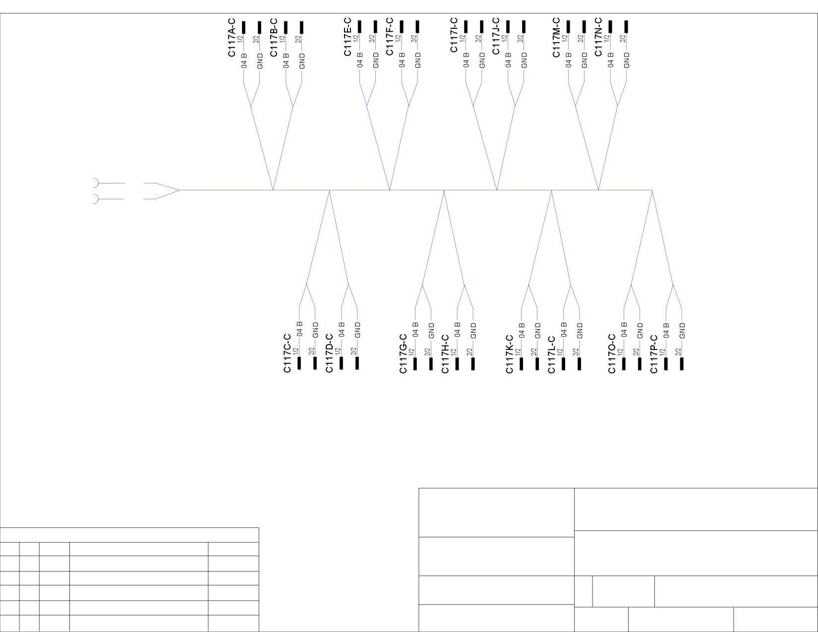
12"
12"
12"
12"
12"
12"
12"
12"
C109-P
1/2
04 B
86"
32"
32"
32"
32"
32"
32"
78"
2/2
GND
12"
12"
12"
12"
12"
12"
12"
12"
NOTE:
1) SEE 0032192 FOR SCHEMATIC.
TITLE:
2) ALL DIMENSIONS ARE SHOWN IN INCHES.
PRECISIONWORKS
MANUFACTURING
READING LIGHT HARNESS, EP3
120 9TH AVE E-4
LONGMONT, CO 80501
REVISIONS
ADDITIONAL INFO:
THIS DRAWING IS THE PROPERTY OF
REV.
BY
DATE
DESCRIPTION
RELEASE #
PRECISIONWORKS MANUFACTURING AND IS
NOT TO BE DUPLICATED OR USED IN ANY
WAY DETRIMENTAL TO THEIR BEST INTEREST.
SIZE:
RELEASE NO.
DWG NO.
MATERIAL SPEC:
A
00000
0032192-160
MODEL:
SCALE
DATE
SHEET
NTS
12/4/07
1
OF
1
Champion
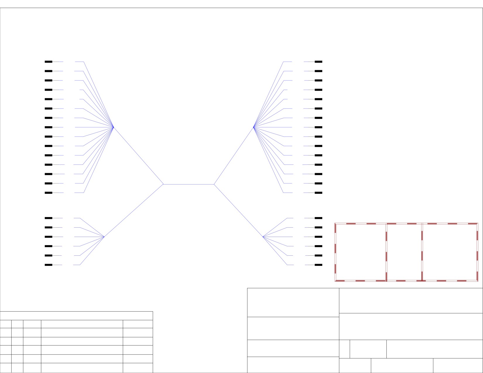
C103-Y-P
C106-R-P
1/15
1/15
28 G
28 G
2/15
2/15
28 P
28 P
3/15
3/15
GND
GND
4/15
4/15
28 G/K
28 G/K
5/15
5/15
28 P/K
28 P/K
6/15
6/15
18 R
18 R
7/15
7/15
03 T
03 T
8/15
8/15
GND
GND
9/15
9/15
09 B
09 B
10/15
10/15
23 Y
23 Y
6"
6"
11/15
11/15
18 Y
18 Y
12/15
12/15
07 I
07 I
13/15
13/15
23 I
23 I
14/15
"DIM A"
14/15
18 O
18 O
15/15
15/15
03 E
03 E
C104-G-P
C111-G-P
1/6
6"
6"
1/6
02 P
02 P
2/6
2/6
07 O
07 O
ELDORADO PN
DIM A
UNIT SIZE
3/6
3/6
07 P
07 P
0032192-122
214"
190/200/210/220
4/6
4/6
0032192-125
239"
240/250
12 O
12 O
5/6
5/6
0032192-129
268"
270/290
18 W
18 W
0032192-130
276"
300
6/6
6/6
09 N
09 N
0032192-132
300"
320
0032192-135
336"
350
NOTE:
TITLE:
PRECISIONWORKS
1) SEE 0032192 FOR SCHEMATIC.
MANUFACTURING
2) ALL DIMENSIONS ARE SHOWN IN INCHES.
LEFT OVERHEAD HARNESS (LENGTH) EP3
120 9TH AVE E-4
LONGMONT, CO 80501
REVISIONS
ADDITIONAL INFO:
THIS DRAWING IS THE PROPERTY OF
REV.
BY
DATE
DESCRIPTION
RELEASE #
PRECISIONWORKS MANUFACTURING AND IS
NOT TO BE DUPLICATED OR USED IN ANY
WAY DETRIMENTAL TO THEIR BEST INTEREST.
SIZE:
RELEASE NO.
DWG NO.
MATERIAL SPEC:
A
00000
0032192-LENGTH
MODEL:
SCALE
DATE
SHEET
NTS
12/4/07
1
OF
1
Champion
WIRING INFORMATION:
08HAB: Connectors are located inside the driver's side frame rail at the BOC.
08HAE: Connectors are located inside the driver's side frame rail at the EOF.
7-Way Connector Information
Wire
Cavity Gauge Color Description
Fuse
Available
Number
Rating
Current
(Amps)
(Amps)
N68BB
A
14
Brown Tail Light
20
20
N56BB
B
16
Yellow Left Turn
10
8
Light
N57BB
C
16
Light
Right Turn
10
8
Green Light
N54BB
D
14
Brown Marker
20
20
Light
N71BB
E
16
Light
Back-up
10
6
Blue
Light
N12BB
F
14
Light
Accessory
20
20
Blue
Feed
N11-GD
G
12
White GND
-
More 7-Way Connector Information
Description
Chassis Harness Body Builder Harness
(4450) 7-Way Connector
2039311C91
2039312C91
Lock
2039342C1
12 Gauge Seals
589390C1
14 Gauge Seals
589391C1
16 Gauge Seals
1652325C1
12 Gauge Terminals
2039344C1
1687848C1
14 Gauge Terminals
3535486C1
2033912C1
16 Gauge Terminals
2039343C1
2033911C1
3-Way Connector Information
Wire
Cavity Gauge Color Description
Fuse
Available
Number
Rating
Current
(Amps)
(Amps)
N56BC
A
16
Orange Left Turn
10
6
Light
N57BC
B
16
Orange Right Turn
10
6
Light
N70BB
C
14
Orange Stop Light
15
15
More 3-Way Connector Information
Description
Chassis Harness Body Builder Harness
(4460) 3-Way Connector
1686834C1
3553961C1
Lock
1664408C1
3554019C1
14 Gauge Seals
589391C1
16 Gauge Seals
1652325C1
14 Gauge Terminals
2033816C1
2033912C1
16 Gauge Terminals
2033819C1
2033911C1
7-Way and 3-Way Connectors for 08HAB (BOC)
7-Way and 3-Way Connectors for 08HAE (EOF)
Section 9 - HVAC & Plumbing
FACTORY AIR CONDITIONING
62
PASSENGER AREA AIR CONDITIONING
62
ROUTINE PREVENTATIVE MAINTENANCE
63
UNDER-THE-HOOD INSPECTION
63
UNDER-THE-BUS INSPECTION
63
EVAPORATOR INSPECTION
64
PASSENGER HEATING
64
SECTION 9
HVAC & Plumbing
AIR CONDITIONING — “IN-DASH” DRIVER AIR
The front HVAC unit supplies fresh outside air or recirculated inside air, heated or cooled, to the driver, to the
front part of the vehicle and to the windshield for defrosting.
The front HVAC unit is located below the dash panel, at the curbside of the vehicle.
Air from the exterior or interior of the coach is forced through the evaporator, the heater core, and the ducts to
the windshield, the driver’s feet, driver’s upper body, and to the front of the vehicle.
The driver may adjust the air outlets to the desired position.
A 3-position switch (OFF/LOW/HIGH) controls the blower speed. The blower motor cannot be rebuilt. When
blower is faulty, noisy or when there is excessive play on motor shaft, replace complete motor and blower wheel
assembly.
The rear evaporator on some buses is ducted to divert some of the A/C output to adjustable aircraft-style vents
located above the windows at each side of the bus. This offers passengers a degree of individual control, but,
overall the main A/C output is directed down the center aisle through louvers in the evaporator. So keep pas-
senger comfort high on your list of priorities and check the “climate” frequently — especially in extremely hot
weather.
All buses equipped with an optional air conditioning system have a single belt-driven compressor. Condensers
are located in the engine compartment and/or skirt mounted. Passenger -system evaporators are located over-
head at the rear of the passenger seating compartment.
AIR CONDITIONING UNIT - PASSENGER AREA
Buses equipped with passenger air conditioning have an evaporator assembly mounted on the ceiling at the rear
of the bus, with separate thermostat and fan-speed controls on the Driver’s Control Console.
For maximum cooling when the bus is first placed into service on a hot day, turn the thermostat and fan-speed
controls to their highest settings. The driver should be sure to monitor passenger comfort and adjust the controls
accordingly. This is especially important in busses that have both passenger and in-dash air conditioning. These
“dual” systems allow the driver to set the temperature and fan controls mounted on the dashboard to cool the cab
area. Always keep in mind that the temperature in the passenger compartment is regulated by the two Control
Consoles and influenced by passenger proximity to entry doors, large windows and the rear evaporator. Become
familiar with the settings that maintain a comfortable and well-balanced climate for all on-board the bus. Refer
to included Carrier’s website or your nearest Carrier dealer for more details.
NOTE: The Control Console’s thermostat control activates the compressor and
must be turned “ON” for either the passenger or driver’s in-dash air conditioning
to operate.
Revised: October 2007
Page 62
Champion Bus, Inc. Maintenance
SECTION 9
HVAC & Plumbing
ROUTINE PREVENTATIVE MAINTENANCE
Maintenance on these three basic A/C components can be divided into three areas. You’ll need to check under
the hood for the compressor and “In-Dash” A/C components, under the bus for the skirt-mounted condenser,
and underneath the Overhead Cover on the ceiling mounted Evaporator Unit.
UNDER-THE-HOOD INSPECTION
Whether your bus has passenger air, in-dash air, or both you’ll need to periodically inspect components under
the hood. With the engine “OFF”, check to see that all A/C fitting, hose clamps, and mounting hardware are
properly tightened. Signs of oil or dirt buildup at a fitting could indicate a leak in the system. Inspect hoses for
signs of wear. Make sure they are not exposed to exhaust heat or routed so they are not rubbing against rough
metal edges.
Check the compressor belt for wear, alignment, and proper tension. Loose or improperly aligned pulleys will
cause belts to vibrate and “dance”. If the belt is correctly tensioned (with engine “OFF”), it should deflect no more
that ½” when pulled “UP” or pushed “DOWN” with a firm hand. Finally, check the sight glass on the condenser
for proper charge. To do this, run the engine at fast idle and engage the compressor clutch by turning the A/C
on high. Let the A/C unit run for several minutes and observe the refrigerant flow through the glass. If it appears
“milky” or “cloudy”, you may need to recharge the system.
UNDER-THE-BUS INSPECTION
This step is necessary if you have one of the larger passenger compartment air conditioners. These units have
a skirt mounted condenser. With the engine “OFF” and no electrical power supplied to the unit, check for built-up
road dirt on the condenser fins. Leaves and other debris that reduce cooling efficiency can usually be removed
with a jet stream of water or high pressure air.
Use a water hose to clean fins by spraying water through the fins from the fan motor side, opposing the airflow
pattern. Turn fans by hand to make sure they rotate freely. Have any damage to fan blades or guards repaired by
your dealer. Check hoses and wiring for signs of wear or improper routing. Keep hoses as far as possible from
exhaust heat. Check hose clamps, electrical connections, and fittings for tightness. Also check fitting for telltale
dirt and oil that could indicate leakage.
Next, start your engine and run at fast idle. Turn the A/C on high and let the unit run for several minutes before
checking the condenser sight glass. Persistent cloudiness indicates low Freon™ charge. Your A/C condenser
has safety cutoffs to protect the unit from overheating, but that can be small consolation on a hot day. So have
your dealer or qualified service technician add refrigerant as soon as possible whenever it is needed.
While the unit is operating, note the air flow across the condenser fins. If hot air is being recirculated, have your
dealer investigate the problem. Carefully touch the hose fitting on the discharge hose (hot gas in). If everything
is functioning correctly, it should be hot. Then touch the hose fitting on the liquid line (liquid out). It should run at
air ambient temperature and may be slightly warm to the touch.
Revised: October 2007
Page 63
Champion Bus, Inc. Maintenance
SECTION 9
HVAC & Plumbing
EVAPORATOR INSPECTION
When the bus is hot, routinely turn “UP” the fan speed control to be sure that the evaporator blower operates
at all three settings. This assures that it can handle a variety of warm weather demands. Note that an
automatic thermal control switch cuts out the highest fan speed when the air temperature inside the bus drops
to moderately cool level.
Check the temperature differential between the air entering and leaving the evaporator. When all major A/C
system components are operating properly, the temperature drop between air “IN” and “OUT” will be between
15° to 20° F.
For a thorough inspection, the evaporator housing must be removed. It is secured with screws. You may want
to refer to the A/C manual supplied by the manufacturer for specific details on removing the housing and
inspecting the evaporator. With the housing removed, make sure the drain lines are secured in place and run
downhill for proper drainage.
Also check the drain pan; it should slope down toward the rear of the bus. If the slope needs adjustment,
loosen the drain pan screws, pull “down” on the rear edge of the pan, and retighten the screws.
Make sure hose clamps and expansion valve fittings are tight. Check hoses for signs of wear and improper
routing (rubbing against metal) and fittings for signs of oil or dirt buildup that might indicate a leak. Removable
interior trim panels along the roadside of the bus provide access to the hoses routing from the condenser to
the evaporator.
With the engine at fast idle and the A/C running, check the sight-glass on the liquid line at the expansion
valve. If needed, have a qualified technician add refrigerant, following manufacturer’s recharging procedures.
While you have the A/C running check the strainer-drier by alternately touching the inlet and outlet sides of
the drier. If both sides feel about the same temperature, the drier is okay. If there is an extreme temperature
change, warm “IN” and cold “OUT”, the drier may be clogged. If so, it should be replaced. Replace the evapora-
tor housing when your inspection is complete. A screwdriver is the only tool needed.
For more information visit: www.transportaircon.carrier.com.
PASSENGER HEATING
Concern for passenger comfort should apply in cold weather as well as hot. Your bus may be outfitted with one
or more low-profile, floor mounted heaters located underneath passenger seating. The heat source for these op-
tional heaters is the same hot engine “coolant” that circulates through the chassis heater core in the driver’s area.
A switch located on the Driver’s Control Console operates a variable-speed fan that draws inside air across the
heating coils of the floor mounted heater. The driver’s in-dash temperature control must be switched to the warm
or hot air range to assure proper coolant flow to the passenger area heater. Drivers should be mindful that the
ambient temperature in the cab may differ considerably from that in the passenger area. They should experiment
with adjustments of the in-dash and floor heater settings until both give suitable comfort levels.
Be sure to check heater fan, hoses, and connections whenever your chassis maintenance schedule recommends
inspecting or servicing the engine coolant system. Hoses are normally routed at the underbody. Make sure
that the hoses are correctly routed and do not rub against metal edges — and that all hose clamps are tight.
Revised: October 2007
Page 64
Champion Bus, Inc. Maintenance
Notes:
Section 10 - Optional Equipment
OVERVIEW
67
TELMA BRAKE RETARDER
67
TELMA ROUTINE MAINTENANCE
67
BRAUN LIFT
68-72
NHSTA OPERATIONS CHECKLIST
68
MAINTENANCE AND LUBRICATION
68
MAINTENACE AND LUBRICATION SCHEDULE
70-72
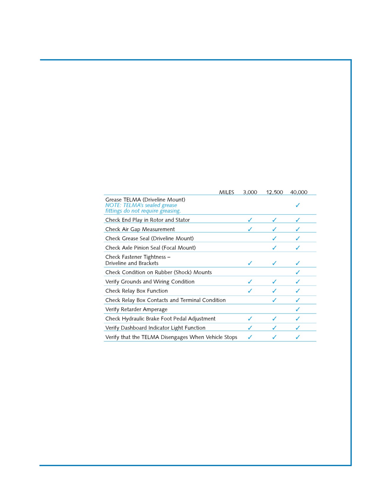
SECTION 10
Optional Equipment
OVERVIEW
There are many options available to your Champion Bus. The following is maintence information for the
options ordered on this bus.
Telma Brake Retarder
The TELMA is a very low maintenance device. However, there are several general maintenance procedures
that can improve the life and performance of your TELMA.
Routine Maintenance Checklist
It is recommended that the TELMA maintenance checklist be incorporated into the regular vehicle
maintenance schedule. The maintenance intervals may vary depending upon the severity of operation and
the annual mileage of the vehicle. The following maintenance schedule is recommended:
Note:
IMPORTANT! In the case of any abnormalities, consult Champion Bus, Inc.
or the factory as soon as possible for assistance in the maintenance of your vehicle.
Revised: October 2007
Page 67
Champion Bus, Inc. Maintenance
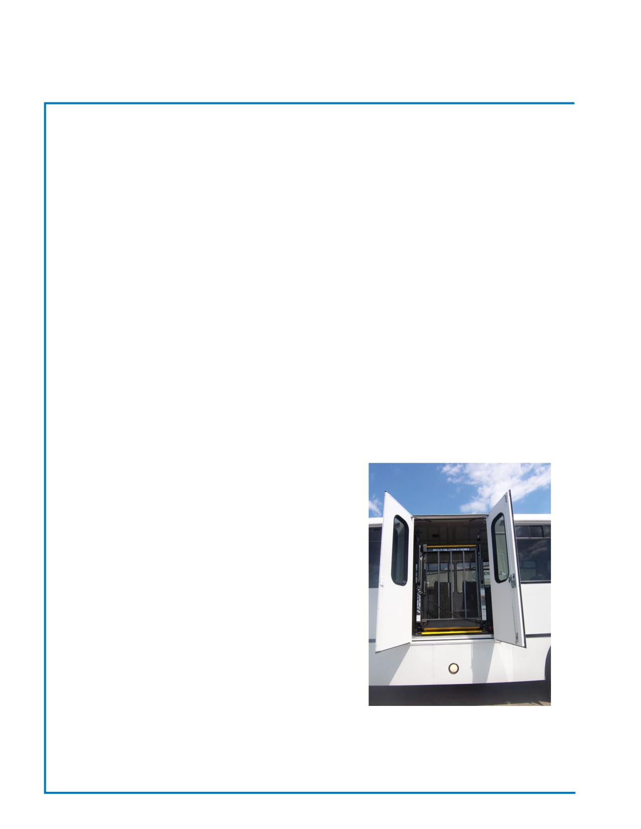
SECTION 10
Optional Equipment
Braun Lift
The Following information has been provided by the Braun Corporation.
NHTSA Operations Checklist
•
Vehicle movement is prevented unless the platform is fully stowed.
•
Lift operation shall be prevented unless the vehicle is stopped and vehicle movement is prevented.
•
The platform will not fold/stow when at least 50 pounds is on the platform.
•
The inner rollstop will not raise if occupied by at least 25 pounds.
•
The outer barrier will not raise if occupied by at least 25 pounds.
•
Verify platform lighting* when lift is deployed and pendant illumination when lift is powered.
•
An audio warning (and visual warning for public lifts) will activate if at least 25 pounds is on the
threshold area when the platform is at least one inch below floor level.
•
Lowering the platform beyond the inner rollstop locking position is allowed only when the inner
rollstop is locked in position.
•
Raising the platform more than 3” off of the ground is prevented unless the outer barrier is raised.
Note:
Public use vehicle manufacturers are responsible for complying with the lift lighting requirements in Federal
Motor Vehicle Safety Standard No. 404, Platform Lift Installations in Motor Vehicles (49 CFR 571.404).
Maintenance and Lubrication
Proper maintenance is necessary to ensure safe, troublefree
operation. Inspecting the lift for any wear, damage or other
abnormal conditions should be a part of all transit agencies’s
daily service program. Simple inspections can detect potential
problems. The maintenance and lubrication procedures specified
in the following schedule must be performed by a Braun
authorized service representative at the scheduled intervals
according to the number of cycles.
NCL Series lifts are equipped with hardened pins and self-
lubricating bushings to decrease wear, provide smooth operation
and extend the service life of the lift. When servicing the lift at the
recommended intervals, inspection and lubrication procedures
specified in the previous sections should be repeated.
Clean the components and the surrounding area before
applying lubricants. LPS2 General Purpose Penetrating Oil is
recommended where Light Oil is called out. Use of improper
lubricants can attract dirt or other contaminants which could result
in wear or damage to the components. Platform components
exposed to contaminants when lowered to the ground may require extra attention. Lift components requiring
grease are lubricated during assembly procedures. When these components are replaced, grease must be
applied during installation procedures. Specified lubricants are available from The Braun Corporation.
Revised: October 2007
Page 68
Champion Bus, Inc. Maintenance
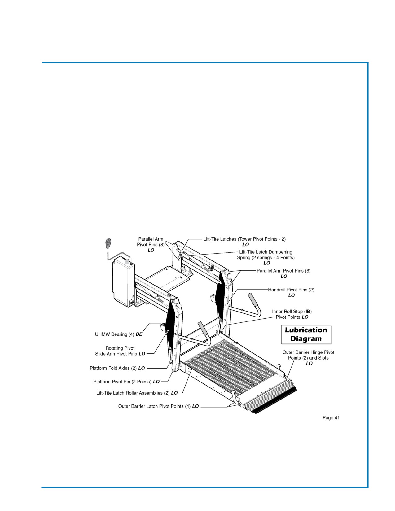
SECTION 10
Optional Equipment
**Maintenance and lubrication procedures must be performed as specified by an authorized service technician.
Failure to do so may result in serious bodily injury and/or property damage.
All listed inspection, lubrication and maintenance procedures should be repeated at “750 cycle” intervals
following the scheduled “4500 Cycles” maintenance. These intervals are a general guideline for scheduling
maintenance procedures and will vary according to lift use and conditions. Lifts exposed to severe conditions
(weather, environment, contamination, heavy usage, etc.) may require inspection and maintenance procedures
to be performed more often than specified.
Discontinue lift use immediately if maintenance and lubrication procedures are not properly performed, or if
there is any sign of wear, damage or improper operation. Contact your sales representative or call The Braun
Corporation at 1-800-THE LIFT. One of our national Product Support representatives will direct you to an
authorized service technician who will inspect your lift.
Revised: October 2007
Page 69
Champion Bus, Inc. Maintenance
SECTION 10
Optional Equipment
Maintenance and Lubrication Schedule
Revised: October 2007
Page 70
Champion Bus, Inc. Maintenance
SECTION 10
Optional Equipment
Maintenance and Lubrication Schedule
Revised: October 2007
Page 71
Champion Bus, Inc. Maintenance
SECTION 10
Optional Equipment
Maintenance and Lubrication Schedule
Revised: October 2007
Page 72
Champion Bus, Inc. Maintenance
Notes:
Typical Maintenance Schedule
BUS MAINTENANCE
75
DRIVER’S RESPONSIBITIES
75
DAILY MAINTENANCE CHECKLIST
76-79
WEEKLY MAINTENANCE CHECKLIST
80
MONTHLY MAINTENANCE CHECKLIST
81
ANNUAL MAINTENANCE CHECKLIST
81
CYCLICAL MAINTENANCE CHECKLIST
82
SEMI-ANNUAL MAINTENANCE CHECKLIST
83
SECTION 11
Maintenance Checklists
BUS MAINTENANCE
The following pages contain checklists that show when certain maintenance procedures should be completed to help
maintain a properly operating bus. These checklists are intended as supplements — not substitutes — for the maintenance
schedules provided by the manufacturers of the vehicle’s chassis or other major components.
These checklists focus on bus maintenance rather than chassis maintenance. The lists are not comprehensive and do not
cover many critical areas such as engine or chassis lubrication. As such, it is the bus owner’s responsibility to consult
the materials assembled in the General Coach America, Inc. Operation, Service, and Parts Manuals for more complete
information on keeping your bus in top condition.
Furthermore, technicians responsible for chassis maintenance should follow the recommendations on service intervals,
maintenance procedures, lubrication specifications, and approved service replacement parts that are provided either in the
chassis Parts, Service or Maintenance manuals. Failure to do so may void the chassis manufacturers’ warranties.
The following checklists are organized into Daily, Weekly, Monthly, Semi-Annual, Annual and Cyclical (dependant on
cycles, mileage or hours) tables so that the lists can be copied and kept in the bus for convenient up-to-date records.
Please note that some items on the checklists may not be applicable to your vehicle and that copies and alterations
can be made as needed for each unit being maintained.
DRIVER’S RESPONSIBILITIES
Regardless of who is responsible for bus maintenance, it is the driver’s responsibility to report —in writing—any problems
they encounter while operating the vehicle. Anything that might affect the safe operation of the bus should be reported
promptly. System malfunctions or unusual conditions including, but not limited to, the following should be reported
immediately:
• Steering
• Brakes
• Lights
• Windshield Washer & Wipers
• Tires
• Power Train (Engine, Transmission)
• Suspension
• Doors
• Windows
• Wheelchair Lifts & Restraints
• Seat Belts
• Unusual Noises
• Unusual Vibrations
• Unusual Exhaust Noise or Fumes
• Unusual Odors (for example; Hot Rubber or Burning Insulation)
Revised: October 2007
Page 75
Champion Bus, Inc. Maintenance
SECTION 11
Maintenance Checklists
MONTHLY MAINTENANCE CHECKLIST
ACCEPTED
ITEM
SUGGESTED
I
IN
I
I
REJECTED
ALL DOOR SEALS
APPLY A LIGHT COAT OF SILCONE TO KEEP RUBBER SUPPLE.
DOO R MOTOR & BASE
CHEC K MOUNTING BOLT & CONTROL ROD'S JAM NUTS FOR
PLATE
TIGHTNESS.
DOO R OPENING &
INSPEC T FOR PROPER SPEED. ADJUST IF NECESSARY.
CLOSIN G SPEEDS
ANNUAL MAINTENANCE CHECKLIST
ACCEPTD
IT
EM
SUGGESTED
I
INITIA
LS
REJECTD
WHEELCHA
I
LIFT
HAVE
DEALER
INSPECT&SERVICE.CHANGEPUMPOIL.
Revised: October 2007
Page 81
Champion Bus, Inc. Maintenance
SECTION 11
Maintenance Checklists
CYCLICAL MAINTENANCE CHECKLIST
ACCEPTED
ITEM
SUGGESTED
I
FREQUENCY
I
I
REJECTED
PASSENGER ENTRY DOO R
INSPECT FOR DAMAGE, LUBRICATE LOWER HINGE PINS
2000 CYCLES
INSPECT FOR DAMAGE & LOOSE BOLTS. LUBRICATE
PASSENGER ENTRY DOO R
6000 CYCLES
UPPER HINGE PINS.
SKIRT MOUNTED
INSPECT, CLEAN COIL & FINS WITH JET OF WATER.
100 HOUR S
CONDENSER
STRAIGHTEN BENT FINS WHEN NECESSARY.
AIR CONDITIONIN G
CHECK COMPRESSOR DRIVE BELT CONDITION &
100 HOUR S
COMPRESSO R
TENSIO N
AIR CONDITIONIN G
CHECK COMPRESSOR CYLINDER UNDER LOAD
100 HOUR S
COMPRESSO R
CONDITIONS. ADJSUT IF NECESSARY.
AIR CONDITIONIN G
COMPRESSOR CLUTCH
CHECK FOR SIGNS OF OVERHEATING OR SLIPPAGE.
100 HOURS
ASSEMBLY
AIR CONDITIONIN G
INSPECT HOSES, HOSE CLAMPS, FAN, FAN GUARD .
300 HOUR S
SYSTEM
INSPECT BELTS & FITTINGS FOR TIGHTNESS.
CHECK REFRIGERENT LEVEL AT RECEIVING TANK
AIR CONDITIONIN G
SIGHT GLASS. CHECK FOR REFRIGERENT OIL LEAKS.
600 HOUR S
REFRIGERENT LEVEL
CHECK A/C CHARGE.
INSPECT FAN BLADES FOR DAMAGE & PROPER
CONDENSER FAN DRIVE
CLEARANCE TO SHROUD. INSPECT BRUSHES FO R
600 HOUR S
MOTOR S
WEAR.
CHECK AIR TEMPERATURE AT “IN” &
“
EVAPORATO R
600 HOUR S
TEMPERATURE SHOULD SHOULD BE 15°F TO 20°F.
EVAPORATOR FIN S
CLEAN COIL & STRAIGHTEN BENT FINS
600 HOURS
REFRIGERENT SYSTEM
CHECK HOSES & TUBING FOR LEAKS
600 HOURS
AIR CONDITIONIN G
CHECK COMPRESSOR & PLATFORM MOUNTING BOLTS
600 HOUR S
COMPRESSO R
FOR TIGHTNESS
AIR CONDITIONIN G
CHECK WIRING HARNESS
600 HOURS
COMPRESSOR CLUTCH
REFRIGERENT PRESSUR E
CHECK WITH MANIFOLD GAUGE
1000 HOURS
100 MILES
DUAL WHEEL LUG NUTS
CHECK TORQUE. TIGHTEN AS NEEDED.
500 MILES
6000 MILES
Revised: October 2007
Page 82
Champion Bus, Inc. Maintenance
SECTION 11
Maintenance Checklists
SEMI-ANNUAL MAINTENANCE CHECKLIST
ACCEPTED
ITEM
SUGGESTED
I
FREQUENCY
I
I
REJECTED
500 MILES
WHEEL LUG NUTS
CHECK TORQUE. TIGHTEN AS NEEDED
6000 MILES
1000 MILES
CHECK TORQUE ON NUTS, BOLTS & FITTINGS. TIGHTEN
AIR RIDE SUSPENSIO N
3000 MILES
OR REPLACE AS NEEDED .
12,000 MILES
REFER TO OEM
BRAKE RETARDER
INSPECT & PERFORM MECHANICAL MAINTENANCE
MANUAL
DRIVER'S SEAT
CHECK SEAT MOUNTING BOLTS FOR TIGHTNESS
6000 MILES
BATTERY, LO W
INSPECT. ADD ELECTROLYTES AS NEEDED .
6000 MILES
MAINTENCE TYPE
PASSENGER SEATS
INSPECT SEAT MOUNTING BOLTS AND BRACKETS.
12,000 MILES
INSPECT WELDS AT FRAME & OUTRIGGERS,
UNDERBOD Y
12,000 MILES
BULKHEADS & BODY FRAME .
BATTER Y
CLEAN & INSPECT
12,000 MILES
TIRES
ROTATE TIRES
12,000 MILES
WHEEL MOUNTING STUD S
INSPECT FOR DAMAGED THREADS.
12,000 MILES
INSPECT FOR DAMAGE OR WEAR. REPLACE
I
AIR RIDE SPRING &
NECESSARY. CORRECT ANY CONDITION CAUSIN G
12,000 MILES
SHOCK ABSORBER S
ABRASION OF AIR BAGS.
TAG AXLE & FRONT PIVO T
CHECK FOR LOOSNESS. RE-TORQUE OR REPLAC E
12,000 MILES
CONNECTION S
PARTS AS NEEDED .
INSPECT FOR FRAYED, LOOSE, CORRODED OR
BATTERY CABLES
24,000 MILES
DAMAGED CABLES.
INSPECT HEADLIGHT ALIGNMENT. ADJUST
I
HEADLIGHTS
24,000 MILES
NECESSARY.
CHECK HARNESSES & CABLES HAVE ENOUGH T
WIRIN G
CLEARANCE FROM SHARP OBJECTS, HEAT SOURCES,
24,000 MILES
AND MOVING PARTS.
HEATER COR E
CLEAN & STRAIGHTEN BENT FINS.
24,000 MILES
CHECK WITH AUTHORIZED SERVICE DEPARTMENT TO
BRAKE RETARDER
30,000 MILES
INSURE PROPER OPERATION .
Revised: October 2007
Page 83
Champion Bus, Inc. Maintenance
INDEX
A
Flooring, Rubber Covering
18
Air Conditioning
Fueling the Vehicle
12
Factory
61
Fuels
12
Inspection
62-63
G
Maintenance
62
Guide, Bolt Torque
9
Passenger
61
H
Hatch, Escape
8
B
Heating
Brake Retarder
66
Cab
3
Breakers
47
Passenger
63
C
L
Cab Area
2
Lift
67-71
Ceiling, Interior
18
Lights
Console, Control
3
Exterior
48
Cooling, Cab
3
Hazard
4
Headlights
48
Interior
48
Marker
48
D
Warning
4
Dash Panel
3
Lubrication
12
Doors
Actuator Trim Panel
37
Adjustments
39
Chassis
37
M
Electric
40
Maintenance Schedules
75-85
Entry, Passenger
37
Maintenance
38
Paratransit
40
P
Panels, Modesty
19
Power Distribution Center
4,47
E
Emergency
Roof Escape Hatch
8
Running out of Fuel
8
R
Starting
6-7
Repair
Warning Kit
7
Electrical System
48
Major Fiberglass
34
Minor Fiberglass
34
Refinishing Fiberglass
34
F
Stress Cracks
34
Fiberglass
Reversing Aid
47
Cap
33
Cleaning
33
Repair
34
Filters
12
INDEX
S
Schematics, Electrical
50-58
Seats
Adjustment
28
Cleaning
25-27
Driver’s
23,28-29
Fabric Care
25
Maintenance
24,25,27
Passenger
23
Safety Requirements
24
Serial Number Tag
2
T
Tiedowns, Wheel Chair
25
Tires
13-14
Changing a Flat
14-15
Jacking Locations
15
Tire Rotation
14
Torque, Bolt Guide
9
Towing
4
Front Hook Up
5
Rear Hook Up
5
Trim, Interior
19
W
Walls, Interior
18
Wheels
13-14
Wheel Chair Tiedowns
25
Windows
Egress
43
Emergence Exit
43
Maintenance
43
Plug
44
Sliding
44