CH-7 PILOT’S OPERATING HANDBOOK

CH-7 HELISPORT S.R.L
CH-77 RANABOT
PILOT’S OPERATING HANDBOOK
This handbook includes material required by
regulation to be furnished to the pilot and must be
carried in the aircraft at all times.
Helicopter Serial Number
--------
Helicopter Registration
---------------
28.01.2022 ENG
Page 1 of 138

CH-7 HELISPORT S.R.L
CH-77 RANABOT
PILOT’S OPERATING HANDBOOK CH-77 RANABOT
SECTION HEADINGS
SECTION 0 GENERAL
4
SECTION 1 DESCRIPTION
7
SECTION 2 LIMITATIONS
25
SECTION 3 EMERCENCY PROCEDURES
35
SECTION 4 NORMAL PROCEDURES
51
SECTION 5 PERFORMANCE
65
SECTION 6 WEIGHT AND BALANCE
75
SECTION 7 OPERATIONS AND MAINTENANCE
83
SECTION 8 SAFETY NOTICES
95
28.01.2022 ENG
Page 2 of 138

CH-7 HELISPORT S.R.L
CH-77 RANABOT
SECTION 0 -GENERAL
CONTENTS SECTION 0
0.1 CORRESPONDENCE RELATING TO THIS HANDBOOK
4
0.2 GENERAL INFORMATION
5
0.3 DESCRIPTIVE DATA
6
28.01.2022 ENG
Page 3 of 138

CH-7 HELISPORT S.R.L
CH-77 RANABOT
SECTION 0 - GENERAL
0.1 CORRESPONDENCE RELATING TO THIS MANUAL
For:
- Additional manuals (cost 5.00
€ by cheque payable to CH7 HELISPORT S.r.l.).
- Technical information.
- Notifying errors or omissions in this handbook.
Please use a copy of this contact sheet and send along with your name and contact details to:
CH-7 HELISPORT S.r.l.
Strada Traforo Del Pino, 102
I - 10132 Torino To
28.01.2022 ENG
Page 4 of 138

CH-7 HELISPORT S.R.L
CH-77 RANABOT
SECTION 0 - GENERAL
0.2 GENERAL INFORMATION
This manual is designed as an operating guide for the pilot. It contains information required to
be furnished by regulation as well as additional data supplied by the manufacturer. It is to be
used in conjunction with the engine manuals published by Rotax as modified by EPAPOWER
documentation and by the manuals pertaining to the EMS, radio and any other fitted
equipment.
These manuals will be periodically updated. The most recent manuals published cancel and
replace all previous versions and are effective from the date of publication. Service Bulletins,
Safety Notices and Airworthiness Directives may also be periodically released and are also
effective from the date of publication. It is the responsibility of the pilot to verify compliance
with all the stipulations and recommendations contained in the latest documentation before
each flight.
As required by the terms of Helisport Service Letter No.1 dated 12.02.2012, the proprietor,
the operator and the pilot must be registered with the manufacturer via the website
assuming the functions of aircraft commander
It is the responsibility of the pilot to ensure the aircraft is airworthy and safe for flight.
An aircraft flight log must be kept and must as a minimum specify the date and duration of
each flight and note the date and details of any anomalies encountered during inspections or
during flight, of the addition oils or coolant, or generally of any operation performed on the
aircraft. It is the responsibility of the pilot to maintain this log accurately. The log must be
presented at each service in order to assist the mechanic correctly assess the condition of the
aircraft.
It is the responsibility of the pilot to respect the limitations indicated on the instruments and
placards and in this manual.
Given the difficulty in referring to a manual while flying a helicopter, the pilot should study the
entire handbook and have become familiar with the limitations, performances, characteristics
and operational procedures before flight.
This manual is divided into numbered sections. The limitations and emergency procedures
appear at the beginning of the manual followed by normal operating procedures,
performances, weight and balance, maintenance and other information.
28.01.2022 ENG
Page 5 of 138

CH-7 HELISPORT S.R.L
CH-77 RANABOT
SECTION 0 - GENERAL
0.3DESCRIPTIVE DATA
CH-77Ranabot:
Two-seat helicopter.
Structure:
Tubular steel welded chassis, composite body.
Main Rotor:
Two blade composite, teetering head.
Tail Rotor:
Two bade, metal.
Power plant:
EPAPOWER SA-R 914-1400 .
EPAPOWER SA-R 917-Ti.
Instruments:
Air speed indicator, altimeter, vertical speed indicator,
compass, rotor and engine tachometer, manifold air
pressure indicator, engine monitoring system.
Equipment:
Single engine coolant radiator coupled with engine oil heat
exchanger, MGB oil radiator,
2 electric fuel pumps,
governor, electric roll and pitch control trim, cockpit voice
alarm and checklist system.
Landing Gear:
Two skids. Amphibious version equipped with floats.
Standard Empty Weight:
283 kg. Basic empty weight variable depending on builder
and equipment. Refer to W&B record for individual aircraft.
Maximum Take Off Weight:
550 kg
Fuel Tank Capacity:
66 litres.
Fuel consumption
(80% at max. continuous power):
33.8 l/h
(SA-R 917-Ti. 30. l/h)
Min fuel consumption in cruise:
20 l/h
(SA-R 917-Ti. 17 l/h)
Useful load:
Variable depending on version (difference between the
maximum take-off weight of the version and the actual
empty weight of the individual aircraft).
28.01.2022 ENG
Page 6 of 138

CH-7 HELISPORT S.R.L
CH-77 RANABOT
SECTION 1 — DESCRIPTION
CONTENTS SECTION 1
1.1
DRAWINGS AND DIMENSIONS
8
1.2
CHARACTERISTICS
9
1.2.1
Main Rotor
9
1.2.2
Tail Rotor
9
1.2.3
Transmission
9
1.2.4
Engine
10
1.2.5
Fuel
10
1.2.6
Lubricants and Coolant
11
1.2.7
Structure
11
1.2.8
Abbreviations and Definitions
12
1.2.9
Conversion Tables
14
1.2.10
Major Component Identification
15
1.2.11
Instruments
15
1.2.12
Instrument Panel
16
1.2.13
Overhead Switch Panel
19
1.2.14
Cabin Interior
21
1.2.15
Accessory Power Outlet
21
1.2.16
Cyclic Pitch Control
22
1.2.17
Voice Alarm and Check-list
23
28.01.2022 ENG
Page 7 of 138
CH-7 HELISPORT S.R.L
CH-77 RANABOT
SECTION 1 - DESCRIPTION
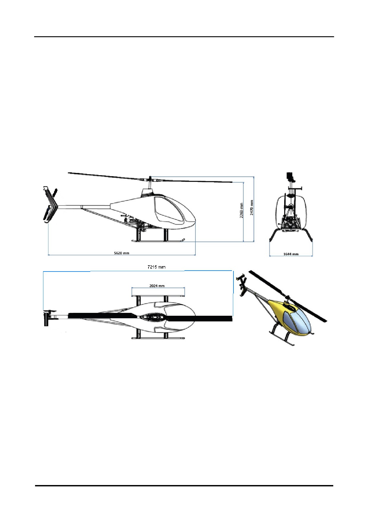
1.1 DRAWING AND DIMENSIONS
28.01.2022 ENG
Page 8 of 138

CH-7 HELISPORT S.R.L
CH-77 RANABOT
SECTION 1 - DESCRIPTION
1.2 CHARACTERISTICS
1.2.1 Main Rotor
Free to teeter and cone, rigid in plane.
Number of blades:
2
Diameter:
6.27 m
Blade chord:
19.4 cm
Blade twist:
6°
Tip speed (at 104 %):
189 m/s
1.2.2 Tail Rotor
Free to teeter, rigid in plane.
Number of blades:
2
Diameter:
1.08 m
Blade chord:
9.7 cm
Blade twist:
8°
Tip speed (at 104%):
176 m/s
1.2.3 Transmission
Engine to upper pulley wheel:
Multigroove V-belt.
Upper pulley wheel to drive line:
Sprag clutch.
Drive line to main rotor:
Spiral bevel gearbox.
Drive line to tail rotor:
Spiral bevel gearbox.
28.01.2022 ENG
Page 9 of 138

CH-7 HELISPORT S.R.L
CH-77 RANABOT
SECTION 1 - DESCRIPTION
1.2.4 Engine
Engine type:
EPAPOWERSA-R 914-1400 (based on Rotax 914).
4 stroke 4 cylinder horizontally opposed.
Drive through reduction gearbox.
2 carburettors.
Electronically controlled turbocharger.
EPAPOWER SA-R 917Ti-.
4 stroke 4 cylinder horizontally opposed.
Drive through reduction gearbox.
Electronic Fuel Injection System.
Electronically controlled turbocharger
Intercooler(*)
(*)The optional installation of an intercooler system is recommended to improve the performance in High
Density Altitude condition.
Displacement:
1 400 cm 3
Maximum power output:
97.kW (130 hp) at 5800 rpm (106%) and 40” MAP. (not applicable)
Take-off power output:
94.7 kW (127 hp) at 5500 rpm (104%)and 40” MAP (5 mins max).
Continuous power output:
80.5 kW (108 hp) at 5500 rpm (104%)and 35.6” MAP.
Cooling:
Liquid and air.
Weight:
71.7 kg
ATTENTION: The EPAPOWER engine is based on the Rotax 914. The latest Rotax 914 manuals
apply to the engine, except where specifically modified by EPAPOWER documentation published
on the website “www.ch-7helicopter.com” or in this manual.
1.2.5 Fuel
Fuel:
Unleaded MOGAS not less than MON 85 or RON 95.
Avgas 91 UL.
Avgas 100 LL (with restrictions see section 2.10 fuel limitations).
28.01.2022 ENG
Page 10 of 138

CH-7 HELISPORT S.R.L
CH-77 RANABOT
SECTION 1 - DESCRIPTION
1.2.6 Lubricants and Coolant
Engine oil specification:
4 stroke engine oil with appropriate additives for reduction
gearboxes. These oils should correspond to the API
classification «SG» or higher. Never use aircraft engine oils
without appropriate additives.
Recommended engine oil:
CH7 HELISPORT S.r.l. recommends Pakelo
900
100%
synthetic .
Engine oil quantity:
3 litres .
Engine oil consumption:
0,08 litre/hour maximum.
Freewheel oil:
MOBIL JET OIL or equivalent.
Quantity:
35 cm3 (as per instructions in the kit assembly manual).
Main gearbox oil:
SWEPCO 201 (SAE 90 ISO 220) or equivalent.
Quantity:
1.3 litres max (1.6 litres if cold).0.9 lt MGB after S/N 145
Tail gearbox oil:
SWEPCO 201 (SAE 90 ISO 220) or equivalent.
Quantity:
40 cm3.
Engine coolant:
Ethylene glycol. EVANS NPG+TM coolant is not to be used.
Recommended coolant:
CH7 HELISPORT S.r.l. recommend VWTLZ
774D/F
(G12/G12+) mixed with water Rate 33%.
Quantity:
3.5 litres max.
1.2.7 Structure
Chassis:
4130 welded steel chassis pressurised with nitrogen gas.
Pressure:
2 bars.
28.01.2022 ENG
Page 11 of 138

CH-7 HELISPORT S.R.L
CH-77 RANABOT
SECTION 1 - DESCRIPTION
1.2.8 Abbreviations and Definitions
PERFORMANCE DEFINITIONS AND ABBREVIATIONS
IAS
Indicated Air Speed. Airspeed as indicated on the airspeed indicator.
CAS
Calibrated Air Speed. Airspeed as indicated on the airspeed indicator
corrected for instrument error and position error.
TAS
True Air Speed. Airspeed relative to surrounding undisturbed air,
equivalent to CAS corrected for pressure altitude and temperature.
VNE
Never Exceed airspeed.
VY
Airspeed for the best rate of climb.
AMSL altitude
Height Above Mean Sea Level. Indicated by the altimeter (corrected for
instrument and position error) when the barometric subscale is set to the
atmospheric pressure currently existing at sea level.
Pressure Altitude
Altitude indicated by the altimeter (corrected for instrument and position
error) when the barometric subscale is set to 1013.2 hPa.
Density Altitude
Altitude in ISA at which the air would have the same density as the air
observed. Equivalent to Pressure Altitude corrected for temperature and
humidity.
ISA
International Standard Atmosphere. Exists when the air pressure at sea
level is
1013,2 hPa, and the temperature at sea level is
15°C and
decreases by 1,98°C per 1000 feet of altitude.
AGL
Above Ground Level.
IGE
In Ground Effect.
OGE
Out of Ground Effect.
MAP
Manifold Air Pressure. Absolute pressure in the engine intake manifold.
RPM
Revolutions Per Minute. Speed of the engine or rotor. Shown on the
tachometer as percentage for ease of appreciation.
MCP
Maximum Continuous Power.
TOP
Take Off Power (limited to 5 minutes duration).
MGB
Main Gear Box.
TGB
Tail rotor Gear Box.
ALT
Alternator.
EMS
Engine Monitoring System.
CAT
Carburettor Air Temperature.
CHT
Cylinder Head Temperature.
EGT
Exhaust Gas Temperature.
MPH
Statute Miles Per Hour.
28.01.2022 ENG
Page 12 of 138

CH-7 HELISPORT S.R.L
CH-77 RANABOT
SECTION 1 - DESCRIPTION
1.2.8 Abbreviations and Definitions (cont)
WEIGHT AND BALANCE DEFINITIONS
Reference Datum
Imaginary vertical plane from which all horizontal distances are
measured for balance purposes.
Station
A longitudinal location along the helicopter fuselage measured
from the reference datum.
Longitudinal Arm
Horizontal distance from the Reference Datum to the Centre of
Gravity of an item.
Lateral Arm
Horizontal distance to the Centre of Gravity of the item measured
from the vertical longitudinal plane passing through the mid-line
between the two skids. A lateral arm towards the right of the
aircraft is expressed as a positive value and a lateral arm towards
the left of the aircraft is expressed as a negative value.
Moment
Product of the weight of an item multiplied by its arm.
Centre of Gravity (CoG)
The point at which the helicopter (or a constituent item) would
balance if suspended.
CoG Arm
Distance from the CoG to the Reference Datum. May be
calculated by dividing the total moment of the constituent items by
the total weight of the helicopter.
CoG Limits
The maximum and minimum CoG arms between which the CoG
must be found for a given total weight.
Usable Fuel
Fuel available for the engine in flight. (Total fuel on board less
unusable fuel).
Unusable Fuel
Fuel remaining in the tanks after engine stops in run out test.
Standard Empty Weight:
Weight of a standard helicopter including Unusable Fuel and full
lubricants and coolant.
Basic Empty Weight
Standard Empty Weight plus weight of installed optional
equipment.
Take Off Gross Weight
Total weight of aircraft, including Load, at take-off.
(TOGW)
Maximum Take Off Weight Maximum permitted TOGW.
(MTOW)
Load
Weight of occupants, baggage and Usable Fuel.
Useful Load
Difference between MTOW and Basic Empty Weight
28.01.2022 ENG
Page 13 of 138

CH-7 HELISPORT S.R.L
CH-77 RANABOT
SECTION 1 - DESCRIPTION
1.2.9 Conversion Tables
METRIC TO IMPERIAL:
MULTIPLY
BY
TO OBTAIN
centimetres (cm)
0.3937
inches (in)
kilograms (kg)
2.2046
pounds (lb)
kilometres (km)
0.5400
nautical miles (nm)
kilometres (km)
0.6214
statute miles (mi)
litres (l)
0.2642
US gallons (gal)
litres (l)
1.0567
US quarts (qt)
metres (m)
3.2808
feet (ft)
kilowatts (kW)
1.3410
horse power(hp)
degrees Celsius (°C)
degrees Fahrenheit (°F)
IMPERIAL TO METRIC:
MULTIPLY
BY
TO OBTAIN
feet (ft)
0.3048
metres (m)
US gallons (gal)
3.785
litres (l)
inches (in)
2.540
centimetres (cm)
inches (in)
25.40
millimetres (mm)
nautical miles (nm)
1.852
kilometres (km)
pounds (lb)
0.4536
kilograms (kg)
US quarts (qt)
0.9464
litres (l)
statute miles (mi)
1.6093
kilometres (km)
horse power(hp)
0.7460
kilowatts (kW)
degrees Fahrenheit (°F)
degrees Celsius (°C)
28.01.2022 ENG
Page 14 of 138

CH-7 HELISPORT S.R.L
CH-77 RANABOT
SECTION 1 - DESCRIPTION
1.2.10 Major Component Identification
COMPONENT OR ASSEMBLY
TYPE
P/N
S/N
Engine
SA-R
Main gear box
CTP RB
Tail gear box
CH709000A
Main rotor hub
CH7070200
Main rotor blade
PLX110K
CSC1010ECH7
Main rotor blade
PLX110K
CSC1010ECH7
Tail rotor blade
CH7101210/C
Tail rotor blade
CH7101210/C
1.2.11 Instruments
FLIGHT INSTRUMENTS
TYPE
Air Speed Indicator
20 mph - 180 mph
Altimeter
HPa:
-1 000 ft / +20 000 ft
Vertical Speed indicator
± 2 000 ft/min
Compass
PAI 700
Hour Meter
LED 6 digits
ENGINE INSTRUMENTS
TYPE
Engine Monitoring System
FlyBox mini EIS ( version CH-77-frontend68)
Engine Monitoring System
Vigilus core 2.27
Engine Monitoring System
SA- D153 SA-C125 -C127EPA Engine 917 Ti Only
Tachometer
3DA5-149KIT
AVIONICS
TYPE
Radio
Transponder (as option)
Flarm
28.01.2022 ENG
Page 15 of 138
CH-7 HELISPORT S.R.L
CH-77 RANABOT
SECTION 1 - DESCRIPTION
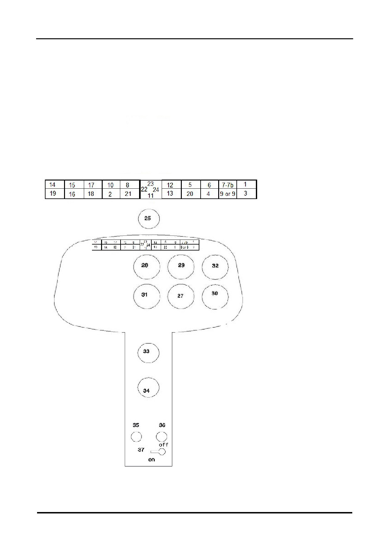
1.2.12 Instrument Panel
LIGHT VERSIONS
28.01.2022 ENG
Page 16 of 138
CH-7 HELISPORT S.R.L
CH-77 RANABOT
SECTION 1 - DESCRIPTION
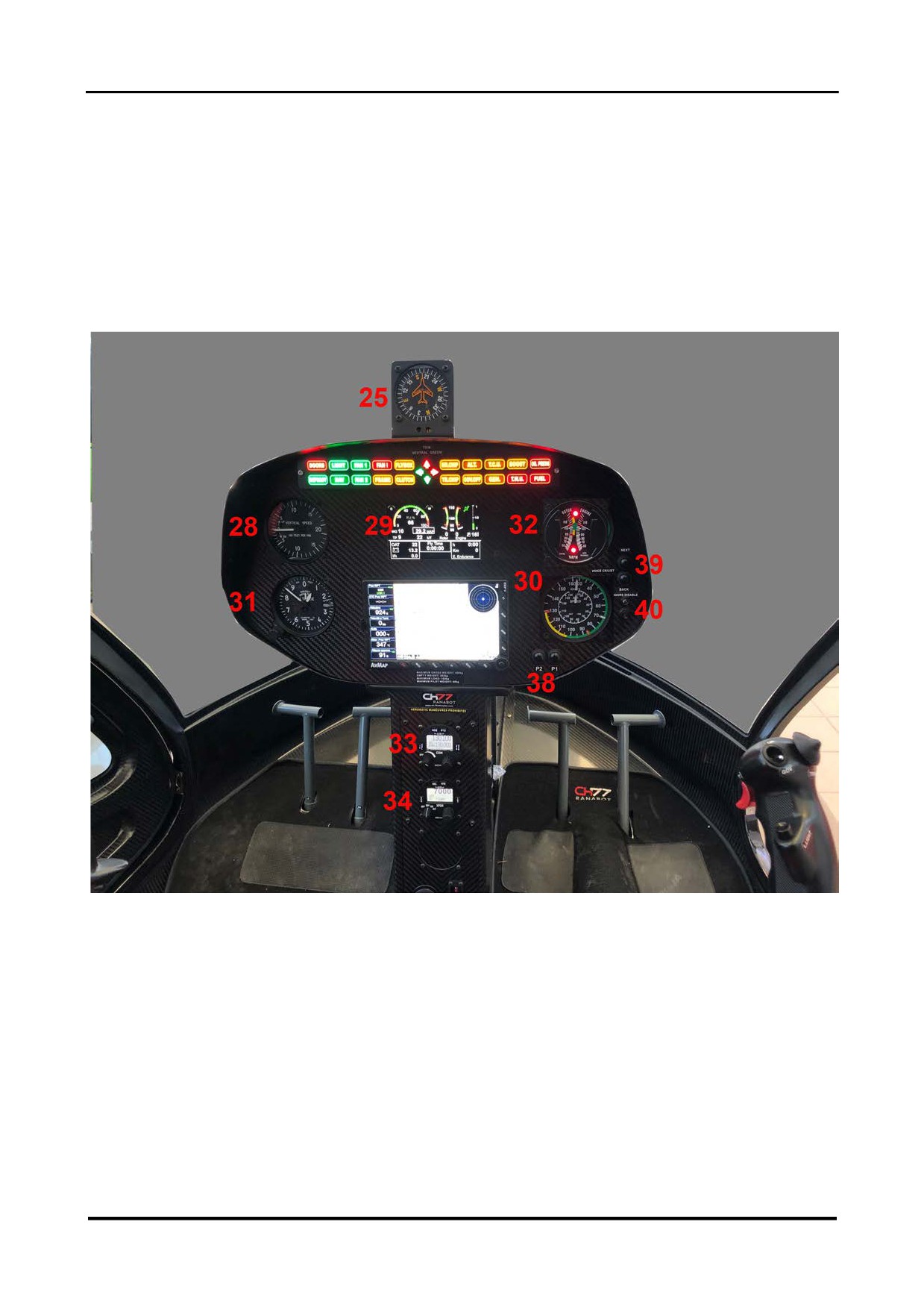
1.2.12Instrument Panel (cont)
STANDARD VERSION 2020
28.01.2022 ENG
Page 17 of 138

CH-7 HELISPORT S.R.L
CH-77 RANABOT
SECTION 1 - DESCRIPTION
1.2.12Instrument Panel (cont)
1
Oil Press-Low oil pressure warning light
red
2
Frame-Frame pressure warning light
yellow
3
Fuel-Low fuel level warning light
yellow
4
Gen-Integrated generator charge failure warning light(*)
yellow
5
Alt-Auxiliary generator charge failure warning light(*)
yellow
6
TCU-Turbo control unit anomaly warning light
yellow
7
Boost-Engine power reach limitation warning light
yellow
7b
Boost-Air Box Temperature extended warning blinking light
yellow
8
Flybox-Engine Monitoring System alarm warning light
yellow
9
F.Press-Low fuel pressure warning light
yellow
9
TWU Turbo Warning Control Unit failure light( version SA-R917Ti)
red
10
Fan!-Engine cooling fan alarm warning light
red
11
Pitch trim neutral indicator light
green
12
MGB chip alarm warning light
yellow
13
TGB chip alarm warning light
yellow
14
Doors- Doors alarm warning light
red
15
Landing light on indicator light
green
16
Navigation lights on indicator light
green
17
Fan1-Engine cooling fan 1 on indicator light
green
18
Fan2-Engine cooling fan 2 on indicator light
green
19
Defrost-Defrost system(if installed)
green
20
Gov.Governor off indicator light
white
21
Clutch-Clutch motor operation light
yellow
22
Roll trim neutral indicator light
green
23
Forward full pitch trim applied indicator light
red
24
Right roll full trim applied indicator light
red
25
Compass
26
Free
27
Manifold air pressure gauge
28
Vertical speed indicator
29
EMS
30
Airspeed Indicator
31
Altimeter
32
Engine / rotor tachometer
33
Radio
34
Transponder
35
Cabin heat control
36
Cabin ventilation control
37
Fuel cock
38
P1 P2 EMS control buttons
39
Voice check list control buttons
40
Doors Voice Disable switch
28.01.2022 ENG
Page 18 of 138
CH-7 HELISPORT S.R.L
CH-77 RANABOT
SECTION 1 - DESCRIPTION
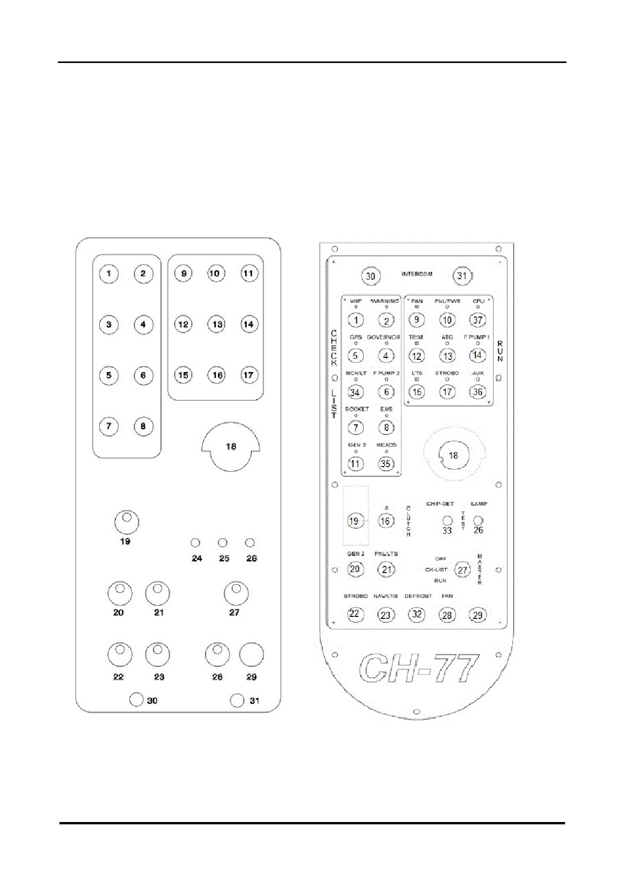
1.2.13 Overhead Switch Panel
EPA SA-R 914
EPA SA-R 917 Ti
28.01.2022 ENG
Page 19 of 138

CH-7 HELISPORT S.R.L
CH-77 RANABOT
SECTION 1 - DESCRIPTION
1.2.13Overhead SwitchPanel (cont)
1
VHF circuit switch breaker
7.5A
2
Warning card circuit switch breaker
2 A
3
Turbo control unit circuit switch breaker
5 A
4
Governor circuit switch breaker
5 A
5
GPS circuit switch breaker
2 A
6
Fuel pump 2 circuit switch breaker
7.5 A
7
Socket power outlet circuit switch breaker
7.5 A
8
EMS circuit switch breaker
2 A
9
Engine cooling fan circuit breaker
2 A
10
Panel power relay circuit switch breaker
5 A
11
Auxiliary generator circuit switch breaker
3 A
12
Control trim circuit switch breaker
3 A
13
Transponder circuit switch breaker
7.5 A
14
Fuel pump 1 circuit switch breaker
7.5 A
15
Lighting circuit switch breaker
5 A
16
Clutch motor circuit switch breaker
2 A
17
Strobe-light circuit switch breaker
5 A
18
Ignition key
19
Clutch switch
20
Auxiliary generator switch button
21
Panel light switch
22
Strobe switch
23
Navigation lights switch
24
MGB chip test button
25
TGB chip test button
26
Warning lights test button
27
Master switch
28
Engine cooling fans switch
29
Spare
30
Headset 2 jack socket
31
Headset 1 jack socket
32
Defrost switch
33
MGB and TGB chip test button
34
Red Beacon light switch breaker
3 A
35
Heads circuit switch breaker
1 A
36
Aux/Hook /Spray System
37
Not used
28.01.2022 ENG
Page 20 of 138
CH-7 HELISPORT S.R.L
CH-77 RANABOT
SECTION 1 - DESCRIPTION
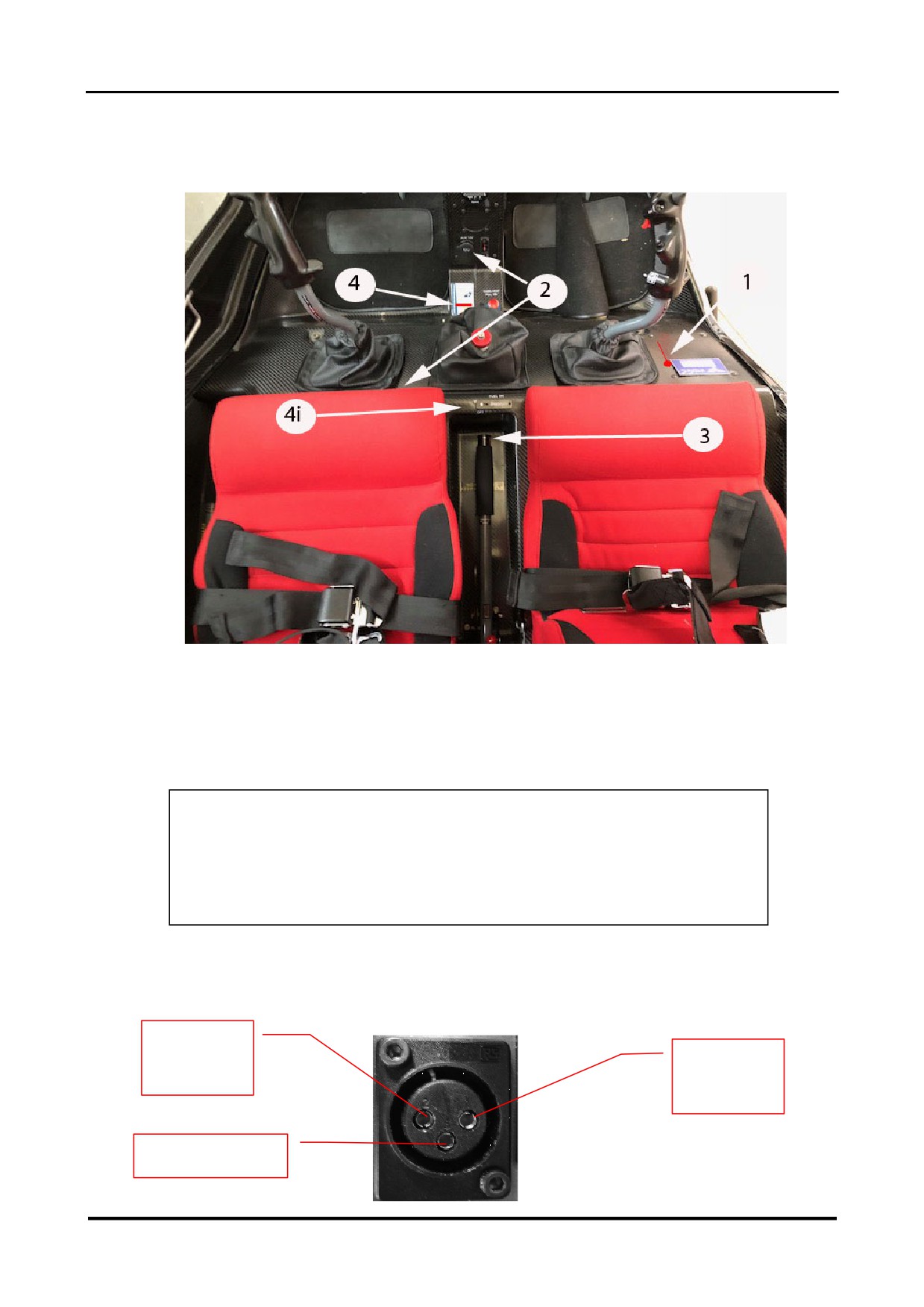
1.2.14 Cabin Interior
1
Choke
2
Accessory 12V power outlet
3*
Starter motor push button (situated on the end of the left hand seat collective control).
4-4i fuel shutoff valve (4i -917Ti Engine)
*ATTENTION: The starter motor push button activates the engine
starter motor only. It does not affect the state of the ignition circuits,
which are controlled by the Ignition Key positions “OFF”, “R”, “L” and
“BOTH” (refer to section « 1.2.13 Overhead Switch Panel» ).
1.2.15Accessory Power Outlet
Type: Kamon
Ground
+12V
Terminal
Terminal
No
28.01.2022 ENG
Page 21 of 138
CH-7 HELISPORT S.R.L
CH-77 RANABOT
SECTION 1 - DESCRIPTION
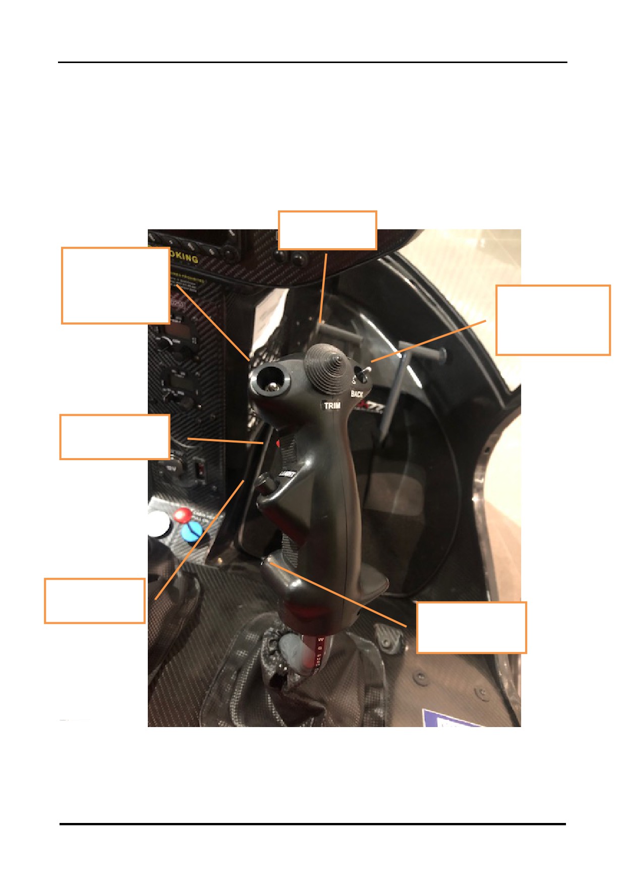
1.2.16 Cyclic Pitch Control
Trim Control
4 directions
Governor Switch
Forward: ON
Aft: OFF
Check List Switch
Forward: NEXT
Aft: BACK
Radio Transmit
Landing Light
EMS Control
Button
28.01.2022 ENG
Page 22 of 138

CH-7 HELISPORT S.R.L
CH-77 RANABOT
SECTION 1 - DESCRIPTION
1.2.17 Voice Check-list and Alarm System
The Voice Checklist and Alarm System is connected directly to the auxiliary input of the radio.
It allows the pilot to complete the start and shutdown procedures without reference to the
paper checklist, and once in flight to hear voice alarms in the event of high or low rotor speed,
low fuel level, or a range of engine parameter anomalies.
To begin the start-up procedure checklist, switch on the radio and move the Master switch to
Checklist. Use the « NEXT » and « BACK » buttons on the instrument panel or the checklist
toggle switch on the cyclic to follow the voice checklist until take-off.
Once the governor control on the cyclic control is switched on towards the end of the start-up
checklist, the voice alarm mode will activate and issue the appropriate voice warning whenever
a warning LED on the tachometer or on the instrument panel illuminates.
After landing, press the green « NEXT » button to leave the voice alarm mode and to activate
the shutdown procedure checklist.
CAUTION:
It is proven that the use of the voice check list reduces the number of
accidents in any case each Pilot must read and understand the
procedures in section 4 before assuming the Pilot in command function, the
paper checklist must always be carried on board per section 7.8
NEXT
button:
Press for the next item on the checklist
(or press
forward on the cyclic checklist toggle switch). Press for
2 secs when in flight (warning) mode to activate the
shutdown procedure checklist.
In flight
(warning) mode press the red and green
buttons simultaneously for the flight time elapsed.
BACK
button:
Press to return to the previous item on the checklist (or
press aft on the cyclic checklist toggle switch).
28.01.2022 ENG
Page 23 of 138

CH-7 HELISPORT S.R.L
CH-77 RANABOT
SECTION 1 - DESCRIPTION
INTENTIONALLY BLANK
28.01.2022 ENG
Page 24 of 138

CH-7 HELISPORT S.R.L
CH-77 RANABOT
SECTION 2 — LIMITATIONS
CONTENTSSECTION 2
2.1
GENERAL
26
2.2
COLOUR CODES FOR INSTRUMENT MARKINGS
26
2.3
AIRSPEED LIMITATIONS
27
2.4
ROTOR
27
2.4.1 Rotor Speed Limitations
27
2.4.2 Rotor Tachometer Indications
27
2.5
ENGINE
28
2.5.1 Manifold Air Pressure
28
2.5.2 Engine Speed Limitations
28
2.5.3 Engine Temperature and Pressure Limitations
29
2.6
TRANSMISSION LIMITATIONS
30
2.7
WEIGHT LIMITATIONS
30
2.8
CENTRE OF GRAVITY LIMITATIONS
31
2.9
OPERATIONS LIMITATIONS
32
2.10
FUEL LIMITATIONS
33
2.11
PLACARDS
34
28.01.2022 ENG
Page 25 of 138

CH-7 HELISPORT S.R.L
CH-77 RANABOT
SECTION 2 — LIMITATIONS
2.1 GENERAL
The information contained in this section concern the operating limitations, instrument
markings and placards required for the safe operation of the helicopter, its engine and other
systems.
CAUTION: Should any of the limitations specified in this section be
exceeded, guidance from an approved agent of CH-7 HELISPORT S.r.l.
MUST be obtained and acted upon before further flight is attempted.
2.2 COLOUR CODES FOR INSTRUMENT MARKINGS
RED:
Indicates operating limits. The needle should not enter into or above the red
zone or line during normal operation.
YELLOW:
Precautionary or special operating procedure range.
GREEN:
Normal operating range.
2.3 AIRSPEED LIMITATIONS
NEVER EXCEED AIRSPEED
VNE:
130 mph
VNE(with door or doors removed):
85 mph
AIRSPEED INDICATOR MARKINGS
Green arc:
40 mph to 100 mph
Yellow arc:
100 mph to 130 mph
Red line:
130 mph
28.01.2022 ENG
Page 26 of 138

CH-7 HELISPORT S.R.L
CH-77 RANABOT
SECTION 2 — LIMITATIONS
2.4 ROTOR
2.4.1 Rotor Speed Limitations
TACHOMETER
ROTOR
Power On:
Max
104%
575rpm
Min
96%
531rpm
Max speed limited to 5 seconds
(Power on in pratic governor off):
106%
586rpm
Power Off (Autorotation):
Max
110%
608rpm
Min
90%
498rpm
2.4.2 Instrument Markings
TACHOMETER COLOUR CODES
Red line:
110%
Upper yellow arc:
104% to 110%
Green arc:
96% to 104%
Central yellow arc:
90% to
97%
Lower red line:
90%
Lower yellow arc:
60% to
70%
Ems: Strictly adhere to FLI green arc operating conditions.
28.01.2022 ENG
Page 27 of 138

CH-7 HELISPORT S.R.L
CH-77 RANABOT
SECTION 2 — LIMITATIONS
2.5 ENGINE
CAUTION: Do NOT start the engine if the helicopter has not
flown for more than 3 months without following the procedure
outlined in Service Bulletin -SB 62.
2.5.1 Manifold Air Pressure
Manifold air pressure:yellow arc
11-13 inches max 3 sec
25% 30% FLI
Manifold air pressure:grenn arc
13 - 35.4inches
30%80% FLI Continuous
Manifold air pressure:yellow arc 35.4- 38inches max 2 min
80%90% FLI per Conditions
Manifold air pressure:red arc
40inches max 1 min
100% FLI per Conditions
2.5.2 Engine/Rotor Speed Limitations
Engine/Rotor speed to5500 rpm (104 % tachometer):
Continuous
Engine/Rotor speed between 5500 rpm (104 %) and 5600 rpm (106 %):
5 sec. maximum
Maximum engine speed limitation not to be exceeded(in star up)
:
5 800 rpm
28.01.2022 ENG
Page 28 of 138

CH-7 HELISPORT S.R.L
CH-77 RANABOT
SECTION 2 — LIMITATIONS
2.5.3Engine Temperature and Pressure Limitations
Airbox temperature(MT):
Max:
79°C
70°C (*)
Airbox temperature(MT)extended(**)
Caution
60°C-70°C (*)
Exhaust gas temperature (EGT):
Max:
950°C
860°C (*)
Normal:
900°C
Cylinder head temperature (CHT):
Max:
120°C
Max normal
110°C
Min normal
75°C
Engine oil temperature:
Max:
125°C
Max normal:
110°C
Min normal:
90°C
Min:
50°C
Engine oil pressure:
Normal:
2 bar to 5 bar
(above 3500 rpm)
Max:
7.0 bar
(during cold start only)
Min:
1.5 bar
(below 3500 rpm only)
(*) Engine 917 Ti only
(**).in case of extended MT temperature over 60 until 70 is expected
progressive power reduction setting and performance loss
due to extended manifold temperature
28.01.2022 ENG
Page 29 of 138

CH-7 HELISPORT S.R.L
CH-77 RANABOT
SECTION 2 — LIMITATIONS
2.6 TRANSMISSION LIMITATIONS
The MGB, TGB, clutch bearing, swash-plate and tail rotor drive shaft bearing are all equipped
with Telatemp temperature recording stickers. Any increase in the maximum temperature
recorded could indicate component deterioration or failure.
Should the first window of any of the Telatemp stickers darken, note the corresponding
temperature and related circumstances in the maintenance record. Flight is permitted.
Should the second window of any of the Telatemp stickers darken, further flight is not
permitted. Contact a maintenance organisation authorised by CH-7 HELISPORT S.r.l.
MGB temperature:
Max:
110°C
TGB temperature:
Max:
66°C
Clutch temperature:
Max:
66°C
Swash-plate temperature:
Max:
66°C
Tail rotor drive shaft bearing temperature:
Max:
66°C
2.7 WEIGHT LIMITATIONS
Standard empty weight:
289 kg
Maximum Take Off Weight:
550 kg
Maximum weight per seat:
108 kg
Minimum pilot plus baggage weight (both doors installed and usable fuel):
69 kg
NOTE
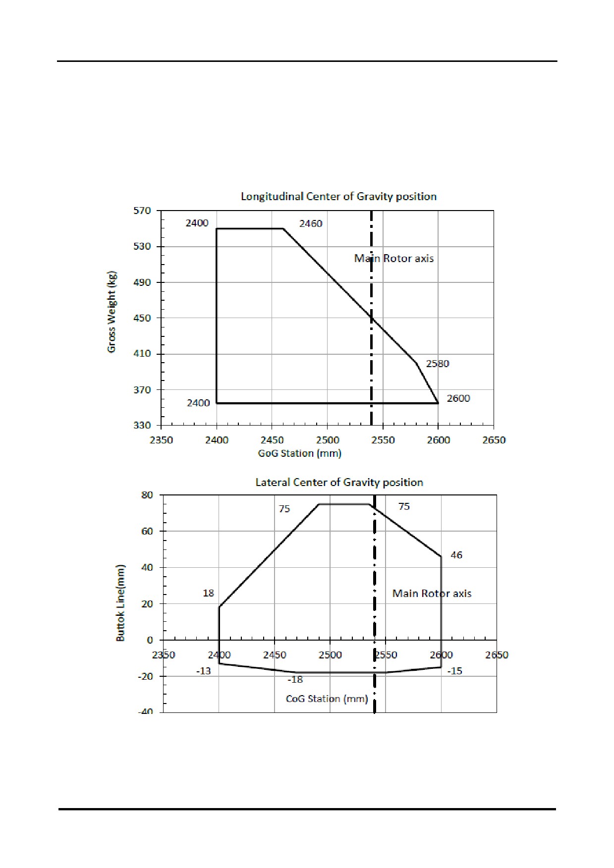
Minimum pilot plus baggage or greater will ensure CG within limitation , for low weight
,compute weight and balance in according to section 6 , removable ballast may be required to
obtain the CG in the limit.
28.01.2022 ENG
Page 30 of 138
CH-7 HELISPORT S.R.L
CH-77 RANABOT
SECTION 2 — LIMITATIONS
2.8 CENTRE OF GRAVITY LIMITATIONS
28.01.2022 ENG
Page 31 of 138

CH-7 HELISPORT S.R.L
CH-77 RANABOT
SECTION 2 — LIMITATIONS
2.9 OPERATIONS LIMITATIONS
Maximum number of occupants: 2.
The pilot and the passenger must be restrained by correctly buckled seatbelts. During solo
flight the passenger seat belt must be buckled.
Solo flight from the left hand seat is prohibited.
Before exercising the function of aircraft commander, the pilot must have satisfactorily
completed a course of instruction as specified in section
« 7.4.1HELISPORT SAFETY
COURSE » of this manual.
Flight with two occupants on board is prohibited with the dual controls fitted unless both the
occupants are qualified helicopter pilots or unless one of the occupants is a qualified instructor.
In normal flight configuration, the aircraft commander occupies the right hand seat and the
passenger occupies the left hand seat. In order to exercise the function of aircraft commander
from the left hand seat, the pilot in the left hand seat must have satisfactorily completed a
course of instruction as specified in section « 7.4.2 RANABOT LEFT SEAT INSTRUCTOR
PILOT COURSE » of this manual.
Aerobatic manoeuvres are prohibited.
Flight in Instrument Meteorological Conditions is prohibited.
Flight in known icing conditions is prohibited.
Flight during snowfall is prohibited.
Avoid flight during rainfall if adhesive protective film is not installed on the leading edges of the
main rotor blades.
In normal flight the governor must be switched on. Flight with the governor switched off is
permitted for training purposes. During flight with the governor switched off, maintain rotor
speed at the upper limit of the green arc (104 %) during take-off, initial climb, approach and
landing, and during all flight at less than 300 ft AGL or above an altitude of 5 000 ft.
Flight with the doors removed at airspeeds not exceeding 85mph is permitted.
Flight with the doors unlatched is prohibited.
28.01.2022 ENG
Page 32 of 138

CH-7 HELISPORT S.R.L
CH-77 RANABOT
SECTION 2 — LIMITATIONS
2.10 FUEL LIMITATIONS
Unleaded Mogas with an octane rating of not less than MON83 or RON 95.
AVGAS 100LL may be used subject to restrictions (see sub-section « 1.2.5 Fuel» and the
latest Rotax engine manuals and Service Bulletins as modified by EPAPOWER
documentation). (no with SA-R 917Ti)
FUEL TANKS
Main tank total capacity
33.5 l
Main tank usable fuel capacity
32 l
Auxiliary tank total capacity
32.5l
Auxiliary tank usable fuel capacity
32.5 l
Low fuel level alarm:
LAND IMMEDIATELY.
The low fuel level warning light and voice alarm
indicate when the fuel remaining will allow less than
approximately 15 mins of further flight.
This reserve level must be calibrated because
differences can exist between individual aircraft.
28.01.2022 ENG
Page 33 of 138

CH-7 HELISPORT S.R.L
CH-77 RANABOT
SECTION 2 — LIMITATIONS
2.11 PLACARDS
NO SMOKING
In clear view of both occupants.
UNLEADED MOGAS
ROZ 95 AKI 91
Next to each fuel filler cap.
100 LL AVGAS(no 917Ti)
TOTAL FUEL CAPACITY 66LITRES
(Main tank 33.5 litres Aux tank 32.5 litres)
Next to main fuel filler cap
FUEL ON - OFF
Next to fuel cock.
MAX LOAD 15KG
In baggage compartment.
MIN PILOT WEIGHT 69KG
In clear view of pilot.
FRICTION ON
- OFF
On collective pitch control.
CHOKE OUT = ON IN = OFF
Next to choke control.
VENT
Next to cabin ventilation control.
HEAT
Next to cabin heating control.
LOCKED - OPEN
Next to door latch on each door.
EMERGENCY EXIT
Next to each emergency door release handle.
LOW G PUSHOVERS PROHIBITED
Next to right hand cyclic control.
SOLO FLIGHT FROM
RIGHT HAND SEAT ONLY
Next to left hand cyclic control.
28.01.2022 ENG
Page 34 of 138

CH-7 HELISPORT S.R.L
CH-77 RANABOT
SECTION 3 — EMERGENCY PROCEDURES
CONTENTSSECTION 3
3.1
POWER FAILURE
37
3.1.1 General
37
3.1.2 Maximum Glide Distance Configuration
37
3.1.3 Power Failure Above 500 ft AGL
38
3.1.4 Power Failure Between 8 ft AGL and 500 ft AGL
39
3.1.5 Power Failure Below 8 ft AGL
39
3.2
DITCHING
40
3.2.1 Ditching Power Off
40
3.2.2 Ditching Power On
40
3.3
TAIL ROTOR FAILURE
41
3.3.1 Tail Rotor Failure in Forward Flight
41
3.3.2 Tail Rotor Failure During Hover
41
3.4
FIRE
42
3.4.1 Fire in Flight
42
3.4.2 Fire During Engine Start on the Ground
42
3.4.3 Electrical Fire in Flight
42
28.01.2022 ENG
Page 35 of 138

CH-7 HELISPORT S.R.L
CH-77 RANABOT
SECTION 3 — EMERGENCY PROCEDURES
CONTENTS SECTION 3 (CONT)
3.5 TACHOMETER FAILURE
43
3.6 CLUTCH FAILURE
44
3.6.1 Clutch Failure During the Start Up Procedure
44
3.6.2 Clutch Failure in Flight
44
3.6.3 Clutch Failure During the Shutdown Procedure
44
3.7 WARNING LIGHTS AND VOICE ALARMS
45
3.7.1 Engine / Rotor Tachometer Warning Lights
45
3.7.2 Instrument Panel Warning and Information Lights
46
28.01.2022 ENG
Page 36 of 138

CH-7 HELISPORT S.R.L
CH-77 RANABOT
SECTION3 — EMERGENCY PROCEDURES
3.1 POWER FAILURE
3.1.1 General
A power failure can be caused by an engine failure or a transmission failure.
An engine failure may be indicated by any combination of the following: a change in noise level
or tone, decreasing engine speed, left yaw and oil low pressure warning light and voice alarm.
A transmission failure may be indicated by any combination of the following: an unusual noise
or vibration, right or left yaw and decreasing rotor speed while engine speed increases.
CAUTION: Aft cyclic is required when collective is lowered at high
speeds and/or forward CG.
3.1.2 Maximum Glide Angle Configuration
1
Approximate airspeed:
70 mph
2
Approximate rotor speed:
96%
3
Maximum glide ratio:
7 : 1
28.01.2022 ENG
Page 37 of 138

CH-7 HELISPORT S.R.L
CH-77 RANABOT
SECTION3 — EMERGENCY PROCEDURES
3.1.3 Power Failure Above 500 ft AGL
1
Immediately lower the collective in order to maintain rotor speed and to enter normal
autorotation.
2
Adjust airspeed to approximately 70 mph.
3
Adjust collective to keep rotor speed in the middle of the green arc.
4
Choose a landing spot and, if the wind permits, manoeuvre so that the landing will be into
the wind.
5
If time permits, attempt to restart the engine using the push button on the collective.
6
Switch off any unnecessary systems and shut the fuel cock.
7
At about 40 ft AGL begin cyclic flare in order to progressively reduce forward speed and
rate of descent.
8
At about 8 ft AGL level the aircraft with a forward action on the cyclic and then raise the
collective as the aircraft descends to cushion the landing. Land with the aircraft horizontal
and the nose straight ahead.
CAUTION: Avoid aft cyclic during the touchdown and
ground slide.
28.01.2022 ENG
Page 38 of 138

CH-7 HELISPORT S.R.L
CH-77 RANABOT
SECTION3 — EMERGENCY PROCEDURES
3.1.4 Power Failure Between 8 ft AGL and 300 ft AGL
1
Take off operation should be conducted according to the Height/Velocity diagram (see
section « 5.6 Height / Velocity Diagram »)
2
In the event of power failure, immediately lower the collective in order to maintain rotor
speed.
3
Adjust collective to keep rotor speed in the middle of the green arc.
4
If time permits, attempt to restart the engine using the push button on the collective.
5
Maintain airspeed until the ground is approached and then begin cyclic flare in order to
progressively reduce forward speed and rate of descent.
6
At about 8 ft AGL level the aircraft with a forward action on the cyclic and then raise the
collective as the aircraft descends to cushion the landing. Land with the aircraft horizontal
and the nose straight ahead.
CAUTION: Avoid aft cyclic during the touchdown and
ground slide.
3.1.5 Power Failure Below 8 ft AGL
1
Apply right pedal as required to cancel left yaw.
2
Slightly lower collective and allow the aircraft to descend.
3
Raise collective just before ground contact to cushion the landing.
28.01.2022 ENG
Page 39 of 138

CH-7 HELISPORT S.R.L
CH-77 RANABOT
SECTION3 — EMERGENCY PROCEDURES
3.2 DITCHING
3.2.1 Ditching Power Off
1
Follow the same procedure as described in section « 3.1 Power Failure » until contacting
the water.
2
Upon water contact, apply right cyclic to stop the rotor.
3
Detach seat belts and evacuate aircraft once the rotor has stopped.
3.2.2 Ditching Power On
1
Descend to hover above water.
2
Detach seat belt.
3
Unlatch doors.
4
Passenger exit aircraft.
5
Fly to a safe distance from passenger to avoid injury from rotor blades.
6
Close throttle.
7
Apply right pedal to cancel yaw, keep aircraft level, apply full collective on water contact.
8
Apply right cyclic to stop the rotor.
9
Evacuate aircraft once the rotor has stopped.
28.01.2022 ENG
Page 40 of 138

CH-7 HELISPORT S.R.L
CH-77 RANABOT
SECTION3 — EMERGENCY PROCEDURES
3.3 TAIL ROTOR FAILURE
3.3.1 Tail Rotor Failure in Forward Flight
1
A tail rotor failure is indicated by right yaw that cannot be corrected by application of the
left pedal.
2
Maintain an airspeed of 70 mph.
3
A small amount of collective with power, coupled with left cyclic, may be applied to
extend range provided the resulting sideslip is not excessive and there is no tendency to
spiral.
4
Adjust the applied collective and left cyclic to vary sideslip angle as required.
5
Choose a landing site, fully roll off throttle, and perform an autorotation landing, keeping
the throttle rolled off while raising the collective by the minimum amount possible
consistent with a safe landing.
3.3.2 Tail Rotor Failure During Hover
1
A tail rotor failure is indicated by right yaw that cannot be corrected by application of the
left pedal.
2
Roll off the throttle and land as described in section « 3.1.5 Power Failure Below 8 ft
AGL »
3
Keep throttle fully rolled off when raising collective at ground contact.
28.01.2022 ENG
Page 41 of 138

CH-7 HELISPORT S.R.L
CH-77 RANABOT
SECTION3 — EMERGENCY PROCEDURES
3.4 FIRE
3.4.1 Fire in Flight
1
Enter autorotation.
2
Open cabin vents.
3
If the engine is running, immediately land normally into the wind and close the fuel cock.
4
If the engine stops running, close fuel cock and perform an autorotation landing.
3.4.2 Fire During Engine Start on the Ground
1
Continue cranking the engine until start in order to suck flames and excess fuel through
the carburettors into the engine.
2
If the engine starts, run at 60 % for a short time then shut down and check for damage.
3
If the engine does not start, close the fuel cock, switch off the Master switch, extinguish
the fire and check for damage.
3.4.3 Electrical Fire in Flight
1
Master Switch off.
2
Generator Switch off.
3
Land immediately.
4
Close fuel cock, switch off engine, extinguish fire and inspect for damage.
28.01.2022 ENG
Page 42 of 138

CH-7 HELISPORT S.R.L
CH-77 RANABOT
SECTION3 — EMERGENCY PROCEDURES
3.5TACHOMETER FAILURE
1
Should either the rotor or the engine tachometer read zero, or otherwise clearly
malfunctions during flight, land immediately using the tachometer that still functions
correctly.
2
Should both the rotor and the engine tachometers read zero, or otherwise clearly
malfunction during flight, but if the engine speed display on the Engine Monitoring
System (EMS)is stable and coherent reading 5 500 rpm, land normally using the EMS
engine speed reading.
3
Should the rotor and the engine tachometers show discordant values in flight, in order to
determine which of them is working correctly, establish an airspeed of 70 mph and then
slowly reduce engine speed with the throttle until the « Low RPM » warning light and
voice alarm activates. The tachometer that indicates approximately 96 % at this point is
correct and should be used to make a normal landing.
4
Should both the rotor and the engine tachometers and the EMS engine speed display not
be working, land immediately using the « Low RPM » warning light and voice alarm to
maintain rotor speed.
5
Unstable rotor and engine speeds, either with or without the simultaneous failure of both
the tachometer readings, could indicate governor failure. Grip the throttle firmly to
override the governor, and switch the governor off. Land using the EMS engine speed
display to manually regulate rotor and engine speed.
28.01.2022 ENG
Page 43 of 138

CH-7 HELISPORT S.R.L
CH-77 RANABOT
SECTION3 — EMERGENCY PROCEDURES
3.6 CLUTCH FAILURE
3.6.1 Clutch Failure During the Start Up Procedure
Clutch failure can cause incorrect transmission belt tension. During every start up procedure,
verify that the clutch activation LED remains lit for 90 seconds (+/- 10%). Should the clutch
operate for longer than 110 seconds, pull the clutch breaker to prevent damage and shut down
the engine. Should the clutch operate for less than 60 seconds, shut down the engine.
Do not take off. Rectify the fault before further flight.
3.6.2Clutch Failure in Flight
In flight, the clutch activation LED will illuminate automatically for a 3 second period if the
circuitry detects that adjustment of the transmission belt tension is required. Should the clutch
activation LED illuminate continuously for more than
6 seconds and the voice alarm
« CLUTCHFAILURE » activate, pull the clutch circuit breaker.
Land normally as soon as possible.
Rectify the fault before further flight.
3.6.3 Clutch Failure During the Shutdown Procedure
During shutdown, if the clutch activation LED does not illuminate, the clutch is inoperative and
the transmission belt will remain under tension. Continue with the shutdown procedure.
Rectify the fault before further flight.
28.01.2022 ENG
Page 44 of 138

CH-7 HELISPORT S.R.L
CH-77 RANABOT
SECTION3 — EMERGENCY PROCEDURES
3.7WARNING LIGHTS AND VOICE ALARMS
3.7.1Rotor / Engine Tachometer Warning Lights
HIGH ROTOR SPEED WARNING LIGHT
• The upper red LED on the tachometer illuminates if the rotor speed is
greater than 104%.
• Reduce rotor speed.
• Associated voice alarm: « OVERSPEED ».
LOW ROTOR SPEED WARNING LIGHT
• The lower red LED on the tachometer illuminates if the rotor speed is
less than 96%.
• If in flight, increase rotor speed.
• Associated voice alarm: « LOW RPM ».
28.01.2022 ENG
Page 45 of 138

CH-7 HELISPORT S.R.L
CH-77 RANABOT
SECTION3 — EMERGENCY PROCEDURES
3.7.2Instrument Panel Warning and Information Lights
1OIL
LOW OIL PRESSURE
• Illuminates if the oil pressure descends below the minimum permitted
(1.5 bar).
• Check the oil pressure gage.if pressure loss is confirmed land
immediatly
• Associated voice alarm: « OIL PRESSURE ».
2FRAME
LOW FRAME GAS PRESSURE
• Illuminates if the gas pressure within the Frame is lost.
• Land as soon as possible and investigate.
• Associated voice alarm: « FRAME PRESSURE ».
3 FUEL
LOW FUEL QUANTITY
• Illuminates if the quantity of fuel remaining in the main tank will allow
only approximately 15 mins of further flight. This duration must be
calibrated as it may vary between individual aircraft.
• Land immediately.
• Associated voice alarm: « FUEL LEVEL ».
4 GEN
INTEGRATED GENERATOR CHARGE FAILURE
• Illuminates if the integrated Main generator fails.
• Land as soon as possible and investigate.
• Associated voice alarm: « GENERATOR ».
• Blinking when the volt is less than 13.5(*)
on the ground in idle engine with low13.5volts is normal
- in fly
monitoring the volts no lower then
12.9 in case Land as soon as
possible and investigate
* With 917 Ti and Atal 8000 regulator only
•
28.01.2022 ENG
Page 46 of 138

CH-7 HELISPORT S.R.L
CH-77 RANABOT
SECTION3 — EMERGENCY PROCEDURES
3.7.2Instrument Panel Warning and Information Lights (cont)
5 ALT
AUXILIARY GENERATOR CHARGE FAILURE
• Illuminates if the auxiliary generator fails.
Land as soon as possible and investigate
• Associated voice alarm: « ALTERNATOR »
• Blinking when the volt is less than 13.5(*)
on the ground in idle engine with low13.5volts is normal
- in
fly
monitoring the volts no lower then
12.9 in case Land as soon
as
possible and investigate
* With 917 Ti and Atal 8000 regulator only
6 TCU
TURBO CONTROL UNIT ANOMALY
• Blinks in the event of a TCU or sensor anomaly.
• Engine performance may be reduced.
• Land as soon as possible and investigate.
• Associated voice alarm:« TCU CAUTION »
• Illuminates continuously if the TCU waste-gate control fails.
• Engine performance will be reduced.
• Land as soon as possible and investigate.
• Associated voice alarm:« TCU WARNING »
7 BOOST
ENGINE POWER LIMITATION
• Illuminates when engine reach or exceeds power. (MAP > 38”).
• Use power in accordance with the limitations defined in section « 2.5.1
Manifold Air Pressure »
• Associated voice alarm:« OVERBOOST »
or
• Illuminates blinking in the event of excessive airbox temperature
(>72°C) or sensor anomaly.
• Engine performance will be reduced.
• Immediately reduce power.
• Associated voice alarm:« AIRBOX TEMPERATURE»
28.01.2022 ENG
Page 47 of 138

CH-7 HELISPORT S.R.L
CH-77 RANABOT
SECTION3 — EMERGENCY PROCEDURES
3.7.2Instrument Panel Warning and Information Lights (cont)
8 FLY BOX
ENGINE MONITORING SYSTEM ANOMALY
• Illuminates if the EMS indicates engine parameters out of limits.
• Determine which parameter(s) is concerned and land as soon as
possible to investigate.
• Associated voice alarm: « INFO FLY BOX »
9 PRESS
LOW FUEL PRESSURE
• Illuminates when the fuel pressure is low.
• Check fuel pump 2 is switched on. Land immediately. Be prepared for
a sudden engine stoppage and for entry into autorotation.
• Associated voice alarm: « FUEL PRESSURE ».
10 FAN
ENGINE COOLING FAN FAILURE
• Illuminates when one or both of the fans fail.
• Manage the engine temperatures by reducing power and choosing
optimal airspeed. Land if unable to maintain operational temperatures.
• Associated voice alarm: « FAN ANOMALY ».
11 TRIM U
PITCH TRIM NEUTRAL
• Illuminates green when pitch control trim is neutral.
12 MGB CHIP
MAIN GEARBOX CHIP DETECTION
• Illuminates when metallic debris is detected in the main gearbox.
• Land as soon as possible and investigate.
• Associated voice alarm: « MAIN ROTOR CHIP ».
13 TGB CHIP
TAIL GEARBOX CHIP DETECTION
• Illuminates when metallic debris is detected in the tail gearbox.
• Land as soon as possible and investigate.
• Associated voice alarm: « TAIL ROTOR CHIP ».
28.01.2022 ENG
Page 48 of 138

CH-7 HELISPORT S.R.L
CH-77 RANABOT
SECTION3 — EMERGENCY PROCEDURES
3.7.2Instrument Panel Warning and Information Lights (cont)
14
Light not currently used.
15 LAND
LANDING LIGHTS ON
• Illuminates when the landing lights are illuminated.
16 NAV
NAVIGATION LIGHTS ON
• Illuminates when the navigation lights are illuminated.
17 FAN 1
ENGINE COOLING FAN 1 ON
• Illuminates when engine cooling fan 1 is in operation.
18 FAN 2
ENGINE COOLING FAN 2 ON
• Illuminates when engine cooling fan 2 is in operation.
19 DEFROST DEFROST system (optional)
• Illuminates when the defrost is switched on.
20 GOV OFF GOVERNOR OFF
• Illuminates when the governor is switched off.
21 CLUTCH
CLUTCH MOTOR OPERATION
• Illuminates when electrical power is applied to the clutch motor. The
lamp will automatically illuminate in flight for a three second period if the
circuitry detects that adjustment of the transmission belt tension is
required.
• If the lamp illuminates continuously in flight for a period of more than 6
seconds, immediately apply the procedure described in section « 3.6.2
Clutch failure in flight ».
• Associated voice alarm: « CLUTCH FAILURE »
28.01.2022 ENG
Page 49 of 138

CH-7 HELISPORT S.R.L
CH-77 RANABOT
SECTION3 — EMERGENCY PROCEDURES
3.7.2Instrument Panel Warning and Information Lights (cont)
21 23 TRIM R ROLL TRIM (otpional)
• Illuminates green when roll control trim is neutral.
• Illuminates green and red when roll control trim is applied right
• Illuminates green when roll control trim is full right.
22 24 TRIM P PITCH TRIM
• Illuminates green when roll control trim is neutral.
• Illuminates green and red when pitch control trim is applied forward.
• Illuminates red when pitch control trim is applied full forward.
28.01.2022 ENG
Page 50 of 138

CH-7 HELISPORT S.R.L
CH-77 RANABOT
SECTION4 — NORMAL PROCEDURES
CONTENTSSECTION 4
4.1 NORMAL OPERATION AIRSPEEDS
52
4.2 DAILY INSPECTIONS
53
4.3 PROCEDURE BEFORE ENGINE START
57
4.4 START UP PROCEDURE
58
4.5 PROCEDURE BEFORE TAKE OFF
59
4.6 TAKE OFF
60
4.7 APPROACH
60
4.8 LANDING
61
4.9 SHUT DOWN PROCEDURE
62
4.10 PRACTICE AUTOROTATION
63
4.10.1 With Power Recovery Below 4 000 ft
63
4.10.2 With Power Recovery Above 4 000 ft
63
4.10.3 With Ground Contact
63
4.11 NOISE ABATEMENT
64
28.01.2022 ENG
Page 51 of 138

CH-7 HELISPORT S.R.L
CH-77 RANABOT
SECTION4 — NORMAL PROCEDURES
4.1 NORMAL OPERATION AIRSPEEDS
Take off and climbs:
60 mph
Maximum rate of climb (Vz max):
55 mph
Maximum range:
85mph
Approach:
60 mph
Autorotation:
70 mph
Max airspeed in turbulent air
100 mph
Never exceed airspeed (VNE):
130 mph
VNEwith doors removed:
85 mph
28.01.2022 ENG
Page 52 of 138

CH-7 HELISPORT S.R.L
CH-77 RANABOT
SECTION 4 — NORMAL PROCEDURES
4.2 DAILY INSPECTIONS
Ensure that lighting conditions are sufficiently bright to properly conduct a visual inspection. If
necessary, use additional lighting.
Before moving the aircraft, purge both fuel tanks.
Clean both main rotor blades and inspect for damage or for cracks in the paintwork. Inspect
condition of tabs and leading edge protection, if fitted.
Clean the windows inside and outside.
Clean and inspect both tail rotor blades.
Remove the engine cowlings.
Vacuum clean the radiators and air filter as required.
ZONE 1 - NOSE SECTION
Slip string: check for condition and secure fixing.
Air inlets: check free from obstruction and operation of opening mechanism.
Pilot tube: check condition, fixing and unobstructed.
Radio and transponder antennae (if fitted): check for secure fixing.
ZONE 2 - CENTRAL LEFT SIDE OF ENGINE COMPARTMENT
Fuel pumps and filters: check for condition and leaks.
Engine coolant hoses: check for condition and leaks.
Radiators and mountings: check for condition and leaks.
Engine oil hoses: check for condition and leaks.
Main gearbox oil: check pump, hoses and radiator for condition and leaks.
Left fuel tank: check for secure mounting and for leaks.
Electrical connectors and probes: check condition.
Clutch: check for condition and wear, check electrical connections.
Transmission nut: check lock-wire.
Tail rotor transmission shaft flexible coupling: check for cracks and secure fixings.
Governor: check for wear and play in connecting rods, check motor for secure fixings.
Exhaust: check for condition and secure fixings.
Left carburettor and inlet manifold rubber flange: check for condition and secure fixing.
Engine coolant: check level and top up if necessary.
Turbo servomotor: check servomotor, electrical connection and cable for condition and fixing.
Left skid: raise the aircraft on its wheels and check condition of the under surface of the skid.
28.01.2022 ENG
Page 53 of 138

CH-7 HELISPORT S.R.L
CH-77 RANABOT
SECTION4 — NORMAL PROCEDURES
4.2 DAILY INSPECTIONS (CONT)
ZONE 3 - TAIL BOOM AND SUPPORT STRUTS
Tail boom and support struts: check fixings are secure and free from play.
Tail rotor drive shaft: check shaft slides longitudinally within its bearings.
Tail rotor drive shaft: check for condition of bearing and secure fixing of bearing housing.
Tail rotor bearing Telatemp: check no change in max recorded temperature.
Support strut attachment collar around tail boom: check for condition and secure fixings.
ZONE 4 - TAIL ROTOR
Blades: check for condition and wear and for the absence of any cracks.
Tail rotor hub: check free from play.
Tail rotor pitch control linkages: check for wear and for free movement and free of play.
Vertical and horizontal empennage: check for condition and secure fixing.
Empennage attachment collar: check for condition and secure fixings.
Tail gearbox oil level: check filler cap secure and oil level through sight glass.
Tail gearbox: check chip detector electrical connections.
Tail gearbox Telatemp: check no change in max recorded temperature.
ZONE 5 - REAR AND CENTRAL LEFT SIDE OF ENGINE COMPARTMENT
Remove right hand fuel tank.
Turbocharger: check for condition and leaks.
Turbo waste-gate: check cable and control linkage for wear and secure fixing.
Engine coolant hoses: check for condition and leaks.
Radiators and mountings: check for condition and leaks.
Electrical connectors and probes: check condition.
Airbox: check for condition and leaks and secure fixings.
Airbox peripherals: check fuel pressure regulator, electrical connections, and fuel and
air
hoses for condition, secure fixing and leaks.
Intercooler (if fitted): check for condition, secure fixing and leaks.
Cabin heater (if fitted): check for condition and secure fixing.
Right carburettor and inlet manifold rubber flange: check for condition and secure fixing.
Air filter and inlet hose: check for condition and secure fixing.
Exhaust: check for condition and secure fixings.
Tail rotor pitch control linkages: check for wear and for free movement and free of play.
Swash-plate and control linkages: check for wear and for free movement and free of play.
Swash-plate Telatemp: check no change in max recorded temperature
28.01.2022 ENG
Page 54 of 138

CH-7 HELISPORT S.R.L
CH-77 RANABOT
SECTION4 — NORMAL PROCEDURES
4.2 DAILY INSPECTIONS (CONT)
Engine oil hoses: check for condition and leaks.
Engine oil: check level and top up if necessary. Battery: check for condition, secure fixing and
electrical connections.
Electrical connections on ground plate and regulator: check for condition and secure fixing.
Main gearbox oil: check for absence of leaks. If any evidence of leakage is detected, check oil
level according to the procedure in the maintenance manual.
Transmission belt: check for wear. Lubricate exterior with silicone spray if you find a lot of belt
dust in the engine compartment.
Lower transmission pulley and cooling fan: check condition and secure fixing with lockwire.
Right skid: raise the aircraft on its wheels and check condition of the skid under surface.
Replace right fuel tank: check for secure mounting and leaks and quick release fuel connector.
ZONE6 - CABIN INTERIOR
Doors: check latches, hinges and emergency releases function and are secure.
(with the door open, put the handle in closed position and check all 3 pins come out, and
with sufficient length, also check that the pins must not rotate 180°by hand, put the
handle back in the open position)
Seat belts: check condition and secure fixing.
Frame pressure: Check 2 bar.
Loose objects: securely stowed.
Flight controls and frictions: check fixings and articulations, free from play and absence of any
loose object that could cause jamming. Lubricate if necessary.
Dual controls (if fitted): check securely fitted.
Instruments and switches: check condition.
Zone 7 -MAIN GEARBOX, MAST AND ROTOR HEAD
Rotor head hub and flanges: check for condition.
Rotor head centring bolts: check tight and lockwired.
Rubber mast protection: Check for signs of mast bumping.
Main rotor pitch control rods: check for condition, absence of play and lockwire.
Rotor blade root: check for secure fixing and condition (absence of cracks in glass upper
surface).
Main gearbox: check chip detector electrical connections.
Main gearbox Telatemp: Check no change in max recorded temperature.
CHECK MAINTENANCE STATUS (BY CALENDAR PERIOD AND BY FLIGHT HOURS)
Note in the appropriate log all programmed maintenance operations, all incidents encountered
and all resulting maintenance operations, accompanied by the corresponding date and number
of flight hours.
28.01.2022 ENG
Page 55 of 138
CH-7 HELISPORT S.R.L
CH-77 RANABOT
SECTION 4 — NORMAL PROCEDURES
4.2 DAILY INSPECTIONS (CONT)
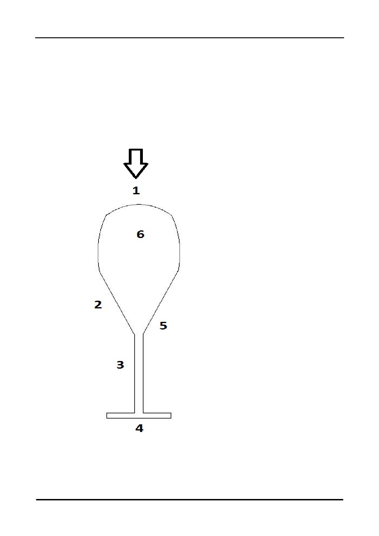
PLAN OF ZONES FOR DAILY INSPECTION
28.01.2022 ENG
Page 56 of 138

CH-7 HELISPORT S.R.L
CH-77 RANABOT
SECTION4 — NORMAL PROCEDURES
4.3 PROCEDURE BEFORE ENGINE START
•
Visually check the quantity of fuel in the tanks. Walk around the helicopter performing a
final check of the aircraft exterior (cowlings properly closed, rotor ties removed, wheels
removed, no loose items in the vicinity of the helicopter, no overhead obstructions, etc).
•
Board the aircraft.
•
If necessary, place a cushion of appropriate thickness behind the pilot’s seat (and behind
the left hand seat if dual controls are fitted) in order to allow the pilots to obtain full travel
of the controls. Ensure that aft cyclic travel is not restricted by the use of the cushion.
•
Put headset on, plug in and switch on if necessary.
•
Check the radio is switched to the on position.
•
Switch « MASTER » to Check list, while verifying that the « TCU » warning light
illuminates briefly and then turns off.(SA-R 914 only) Verify the previous flight time
announced by the Voice Check List is consistent with the last entry in the aircraft log and
then continue as follows as prompted by the Voice Check List.
•
Check the voltage battery not below 13.0 volt. if it is lowered then 13.0 volt or less and it
is lithium tipe , abort the start ,perform a re charge of battery , use a specific lithium
charger. Caution never use the starter boost direct to battery pole, if is necessary use it
and apply only to pole of electric starter.
•
Ensure both seat belts are buckled, , whether or not the left hand seat is occupied.
Check both doors are closed and properly latched by both the main latch handle and the
upper forward latch. Check the emergency door release handles are in place and
physically touch them in order to better recall their positions should an emergency arise.
Brief the passenger on the emergency exit procedure.
•
Check the fuel cock is open, verify there is sufficient fuel and reserve for the planned
flight, and enter the fuel quantity as previously visually verified into the EMS.
•
Release the cyclic and collective frictions and check that full and free movement of all
combinations of the cyclic and collective controls and the pedals is present. Fully lower
the collective, set the cyclic and pedals in their neutral positions, and tighten the frictions.
•
Ensure all switches (except for « MASTER ») are off and that all circuit breakers are in.
•
Set the altimeter according to the QNH or QFE pressure, as appropriate.
•
Check the frame pressure is present (approximately 2 bar).
28.01.2022 ENG
Page 57 of 138

CH-7 HELISPORT S.R.L
CH-77 RANABOT
SECTION 4 — NORMAL PROCEDURES
4.4 START UP PROCEDURE
•
If the engine is cold, move choke lever to « CHOKE ON (SA-R914 only)».
•
Switch « MASTER » to Run and check the Oil Pressure, Generator,Alt. and Governor
(TCU* )warning lights are illuminated
•
Check the voltage battery not below 13.0 volt. if it is lowered then 13.0 volt or less and it
is lithium tipe , abort the start ,perform a re charge of battery , use a specific lithium
charger. Caution never use the starter boost direct to battery pole, only to pole of electric
starter.
•
Check the fuel pressure warning light is extinguished and verify the fuel pressure reading
on the EMS Pump 1. Switch « Clutch»on and check the fuel pressure (reading increases
with pump 2). Switch « Clutch » off.
(reading increases with SA-R914 Engine Pump1 0.37bar increases Pump2 0.52 bar )
(reading increases with SA-R917 Engine Pump1 3.0bar increases Pump2 3.3 bar )
•
Check the throttle is fully closed.
•
Check the vicinity of the helicopter is free from obstructions and hazards.
•
Start the engine using the collective starter motor push button (max 5 second each)until
the oil pressure light extinguishes (minimum 1. bar). Without releasing the starter motor
push button, turn the ignition key to « R - L and then BOTH ».(TCU* light off) Once the
engine starts, release the push button. Check the engine speed is not less than 1 800
rpm.
•
Without delay, switch the clutch on, check the clutch light illuminates and note the time
.Do not allow the engine to run for more than 10 seconds with the transmission belt
loose. The clutch must be engaged as soon as the engine is started and oil pressure is
established, otherwise pulley and transmission belt damage may occur.
•
check the voltage to increase
•
Carefully turn the throttle from fully closed in order to take up the slack in the throttle
cables up to the point at which the engine just begins to respond. Move the choke lever
to « CHOKE OFF if installed ».
•
Note the time at which the clutch light extinguishes. Carefully check the clutch motor
does not run for more than 90 secs ± 10%. A longer or shorter running time will result in
incorrect transmission belt tension.
•
If the transponder is fitted, switch it to « STANDBY ».
•
When the engine oil temperature reaches 35°C, increase the engine speed without
pause to between 70% and 80%. Do not allow the rotor speed to rest in the range of55%
to 70% in order to avoid the resonance that occurs within this zone.
•
Turn the ignition key from « BOTH » to « R » and check the engine speed drops by no
more than 150 rpm after 3 seconds. Turn the key back to « BOTH » and allow the engine
speed to re-establish. Turn the ignition key from « BOTH » to « L » and check the
engine speed drops by no more than 150 rpm after 3 seconds. Turn the key back to «
BOTH ».
28.01.2022 ENG
Page 58 of 138

CH-7 HELISPORT S.R.L
CH-77 RANABOT
SECTION 4 — NORMAL PROCEDURES
•
When the engine oil temperature reaches 50°C, increase the engine speed to 90% and
then cut the throttle. Verify the transmission free wheel operates by checking the
tachometer needle split (the tachometer engine speed needle should drop rapidly to
40/50% while the rotor speed needle declines more slowly). Check the engine speed with
the throttle fully reduced is not less than 1 800 rpm and not more than 2 650 rpm
(40/50%).
(*only with SA-R 917 Ti)
4.5 PROCEDURE BEFORE TAKE OFF
•
Check the doors are closed and latched.( Pay particular attention to the correct closing of
the doors use both hands on the two handles and apply force inwards, with the front
hand lock the door by pushing the handle first forward and then downwards, turn your
head back and check that the door is in its seat there must be no light between the door
and the door frame. apply a force with your arm outwards so make sure that the three
pins are properly inserted .repeat the procedure for the passenger door .It is
recommended that the pilot close the passenger door from outside before taking a seat
on the aircraft.)check panel light DOOR is off
•
Check the fuel cock is open and the choke is off .
•
Check all circuit breakers are all in
•
Press « TEST » buttons and check all warning lights illuminate.
•
Release the cyclic friction.
•
Release the collective friction, verify the oil temperature is over 50°C, increase the
engine speed to 90% and switch the governor on. Check the engine and rotor speeds
stabilise at 104%.
•
Check the outside temperature and verify the expected aircraft performance is
compatible with the planned flight.
•
Check all engine parameters are within normal limitations.
•
Set the radio volume and frequency.
•
If the transponder is fitted, switch it to « AC »
•
Check the wind strength and direction and that the vicinity of the aircraft is still clear of
any hazards.
•
Slowly reduce the engine speed and verify that the low rotor speed warning light and
voice alarm activate at 96%. Release the throttle and allow the governor to re-establish
engine and rotor speed of 104%.
•
Ready for take-off.
28.01.2022 ENG
Page 59 of 138

CH-7 HELISPORT S.R.L
CH-77 RANABOT
SECTION4 — NORMAL PROCEDURES
4.6 TAKE OFF
1
Slowly raise the collective pitch control while turning the throttle to accompany the
governor as it maintains 104% engine and rotor speed.
2
Stabilise the helicopter in hover IGE.
CAUTION: Check the presence of the ground effect by observing the decrease
in MAP as the helicopter descends and ground effect is entered. Ground effect
with the CH-77 is generally effective below a skid height of 50cm.
3
Check engine parameters are within normal limitations.
4
Move the cyclic pitch control forwards and accelerate to climb airspeed while remaining
within the profile shown in the height / velocity diagram section « 5.6
HEIGHT /
VELOCITY DIAGRAM ».
5
Maintain rotor speed at the upper limit of the green arc during take-off and climb.
4.7APPROACH
1
Maintain engine
/ rotor speed at
104% and engine instruments within green arc.
Establish final into the wind at an airspeed of 60 mph.
2
Progressively reduce airspeed and altitude to hover IGE while remaining within the
profile shown in the height / velocity diagram section « 5.6 HEIGHT / VELOCITY
DIAGRAM ».
3
Ensure the vertical speed of descent is less than 500 ft/min before allowing the airspeed
to descend below 30 mph.
28.01.2022 ENG
Page 60 of 138

CH-7 HELISPORT S.R.L
CH-77 RANABOT
SECTION4 — NORMAL PROCEDURES
4.8 LANDING
1
From a stabilised hover in ground effect, progressively lower the collective until ground
contact while maintaining a constant heading with the pedals.
2
After initial ground contact, fully lower collective.
CAUTION: When landing on a slope, move the cyclic to
its neutral position before fully lowering the collective.
28.01.2022 ENG
Page 61 of 138

CH-7 HELISPORT S.R.L
CH-77 RANABOT
SECTION4 — NORMAL PROCEDURES
4.9SHUT DOWN PROCEDURE
•
Lower the collective to its full down position and apply the friction.
•
Press « NEXT » and continue as follows as prompted by the Voice Check List.
•
Switch the governor off and slowly reduce the engine speed to between 70% and 80%
and note the time.
•
Adjust the pitch and roll trims to neutral.
•
Switch the « FAN » on
•
60 seconds after the engine speed reduction, further reduce the engine speed to 50%
and apply the cyclic friction.
•
Allow the CHT and Engine Oil temperature to fall below 90°C. Do not switch off the fan in
order to allow it to continue to cool the turbo.
•
Switch the « CLUTCH » off, check the clutch light illuminates and note the time.
•
40 seconds after the clutch motor start, Switch off the ignition key,
•
Switch off the ignition key and Switch MASTER in check list position.
•
Note the time at which the clutch light extinguishes. Carefully check the clutch motor
does not run for more than 100 secs ± 10%. A longer or shorter running time is indicative
of incorrect clutch adjustment. Contact an approved agent of CH-7 HELISPORT S.r.l. for
guidance.
•
Switch « MASTER » to off and all Switch off
•
Enter the flight details into the aircraft log book. See section
« 0.2GENERAL
INFORMATION »
CAUTION:
Never attempt to slow the rotor during shutdown by raising the
collective. The blades could flap and strike the tail boom.
CAUTION:
Hold the throttle closed if the occupant of the left hand seat is
entering or leaving the helicopter with the dual controls installed.
CAUTION:
Never leave the flight controls unattended while the engine is
running.
CAUTION:
In order to avoid evaporation and corrosion in the fuel circuit,
only close the fuel cock in case of necessity for maintenance or
for safety reasons.
28.01.2022 ENG
Page 62 of 138

CH-7 HELISPORT S.R.L
CH-77 RANABOT
SECTION4 — NORMAL PROCEDURES
4.10 PRACTICE AUTOROTATION
4.10.1 With Power Recovery Below 4 000 ft AMSL
1
Fully lower the collective without reducing the throttle.
2
Reduce the throttle to split the tachometer needles.
3
Maintain the rotor speed in the middle of the green arc and maintain an airspeed of
70 mph.
4
At about 40 ft AGL, begin cyclic flare in order to progressively reduce forward speed and
rate of descent. At about 8 ft AGL level the aircraft with a forward action on the cyclic
and then as the aircraft settles stop the descent by raising the collective while rotating the
throttle back to its original position.
4.10.2 With Power Recovery Above 4 000 ft AMSL
1
Proceed as described above in section 4.8.1, except slightly reduce the throttle before
lowering the collective, and reopen the throttle slightly before raising the collective.
2
After commencing the final approach, maintain a minimum engine speed of 70%.
4.10.3With Ground Contact
1
Should it be necessary to demonstrate autorotation to ground contact, proceed as
described above in section 4.8.1, except that as the aircraft settles, accompany it to
touchdown by raising the collective to a lesser degree.
2
Ensure the skids are level and the nose is straight ahead at touchdown and throughout
the ground slide.
28.01.2022 ENG
Page 63 of 138

CH-7 HELISPORT S.R.L
CH-77 RANABOT
SECTION 4 — NORMAL PROCEDURES
4.11NOISE ABATEMENT
To improve the quality of the environment, and so as not to provoke the introduction of
restrictive public regulation, it is important that each pilot causes the least possible noise
irritation to the general population.
Whenever possible:
1
Avoid over-flight of any assembly of people.
2
Avoid blade slap. Blade slap occurs during shallow high-speed descents, and especially
while turning. Prefer a slower steeper descent profile. Better piloting technique can easily
eliminate blade slap.
3
Avoid low level flight under 1000 ft AGL. Increased height greatly reduces noise levels.
4
Repetitive noise is much more irritating than a single occurrence. If flight over the same
area must be made more than once, vary the flight path to avoid over-flight of the same
buildings each time
CAUTION: The recommended noise abatement procedures above
should not be applied should they be incompatible with air traffic control
procedures or would result in an unsafe flight path.
28.01.2022 ENG
Page 64 of 138

CH-7 HELISPORT S.R.L
CH-77 RANABOT
SECTION5 — PERFORMANCE
CONTENT'S SECTION 5
5.1 GENERAL
66
5.2 ALTITUDE DENSITY DIAGRAM
67
5.3 IGE HOVER CEILING / GROSS WEIGHT
68
7
5.4 OGE HOVER CEILING / GROSS WEIGHT
69
5.5 NEVER EXCEED AIRSPEED / ALTITUDE
70
5.6 HEIGHT / VELOCITY DIAGRAM
71
5.7 ENGINE PERFORMANCE DIAGRAMS
72
28.01.2022 ENG
Page 65 of 138

CH-7 HELISPORT S.R.L
CH-77 RANABOT
SECTION5 — PERFORMANCE
5.1 GENERAL
Hover controllability has been demonstrated in winds of 15 knots from any direction up to a
density altitude of 11 500 ft.
Refer to the IGE hover ceiling diagram for the maximum allowed gross weight.
CAUTION:
The performance data presented in this section was obtained
under ISA conditions with engine SA-R 917Ti with
intercooler.
28.01.2022 ENG
Page 66 of 138
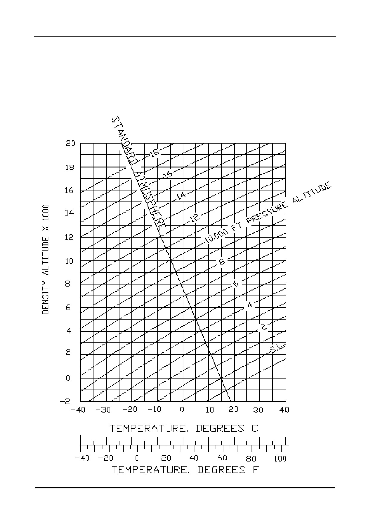
CH-7 HELISPORT S.R.L
CH-77 RANABOT
SECTION 5 — PERFORMANCE
5.2 ALTITUDE DENSITY DIAGRAM
28.01.2022 ENG
Page 67 of 138
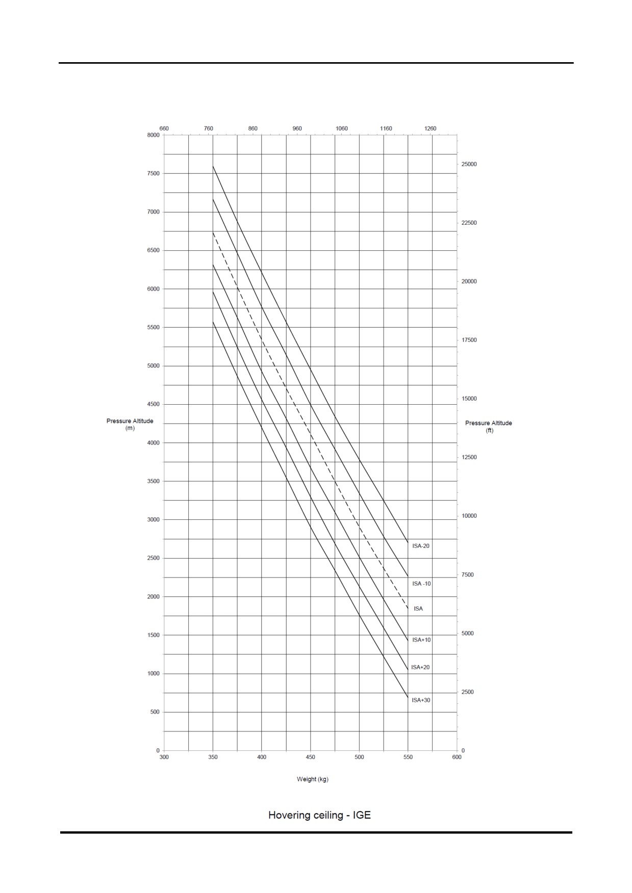
CH-7 HELISPORT S.R.L
CH-77 RANABOT
SECTION 5 — PERFORMANCE
5.3 IGE HOVER CEILING / GROSS WEIGHT
28.01.2022 ENG
Page 68 of 138
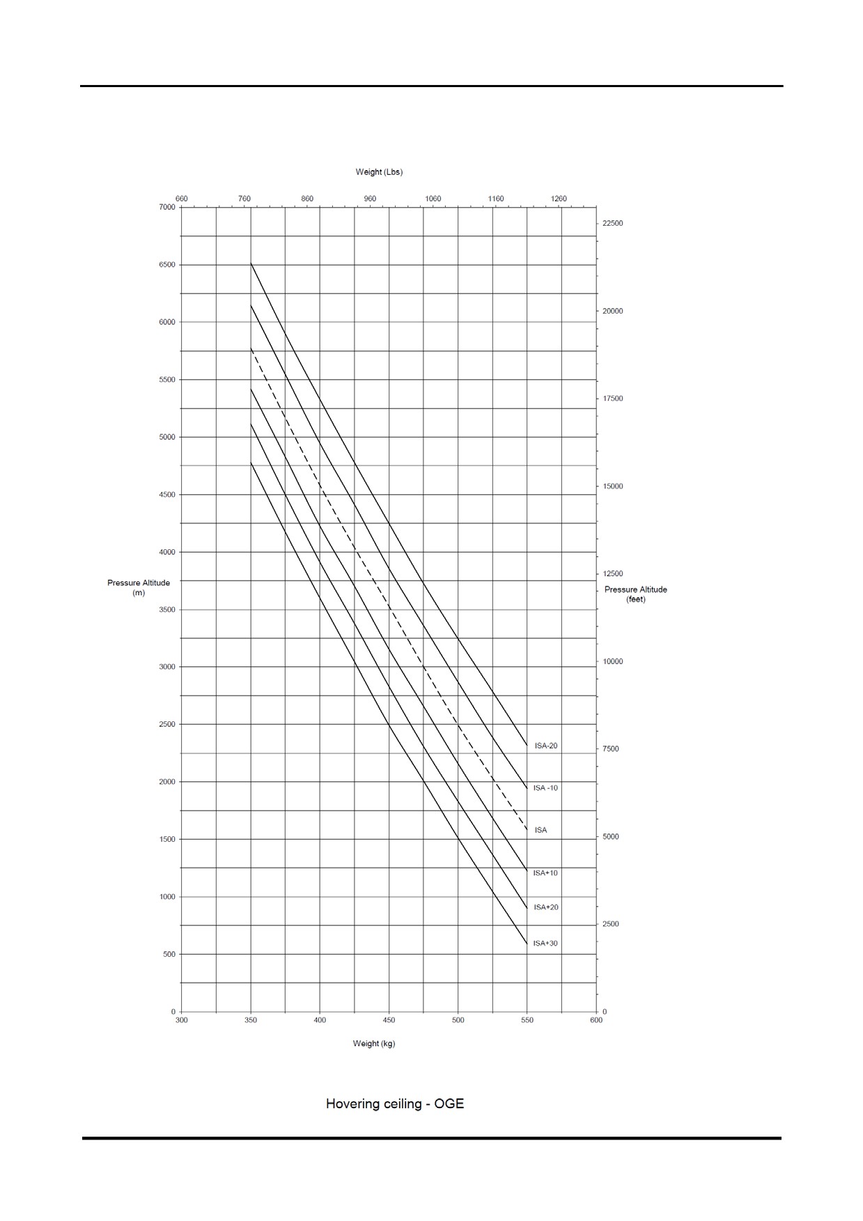
CH-7 HELISPORT S.R.L
CH-77 RANABOT
SECTION5 — PERFORMANCE
5.4 OGE HOVER CEILING / GROSS WEIGHT
28.01.2022 ENG
Page 69 of 138
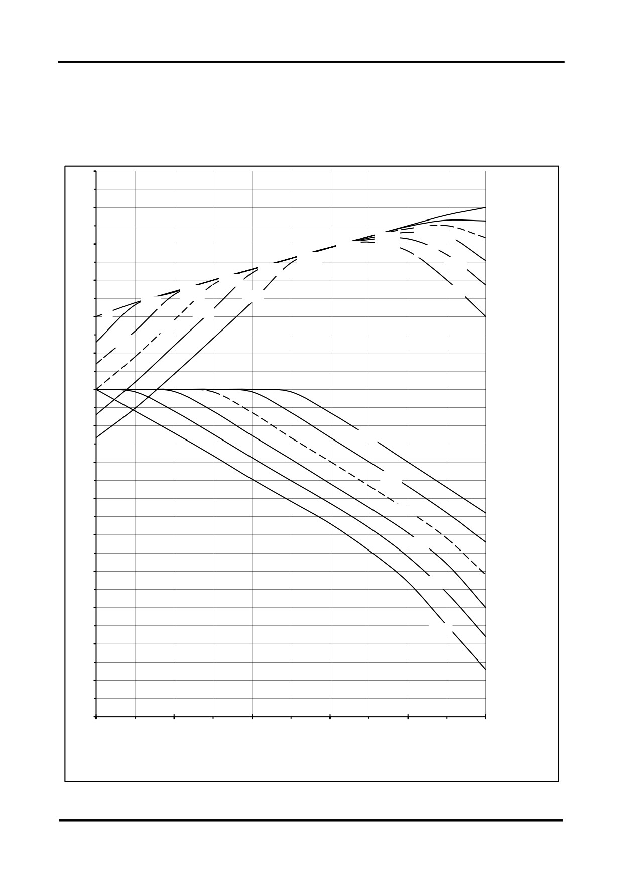
CH-7 HELISPORT S.R.L
CH-77 RANABOT
SECTION5 — PERFORMANCE
5.5 NEVER EXCEED AIRSPEED / ALTITUDE
250
240
400
+10°
230
3500
3000
4000
2500
5000
+20°
2000
220
1500
1000
+30°
-20°
500
-10°
210
0
5000
ISA
TAS
+10°
(km/h)
0
190
180
-20°
170
-10°
160
IAS
ISA
(km/h)
150
+10°
140
+20°
130
+30°
120
110
100
0
1000
2000
3000
4000
5000
Pressure Altitude (m)
28.01.2022 ENG
Page 70 of 138
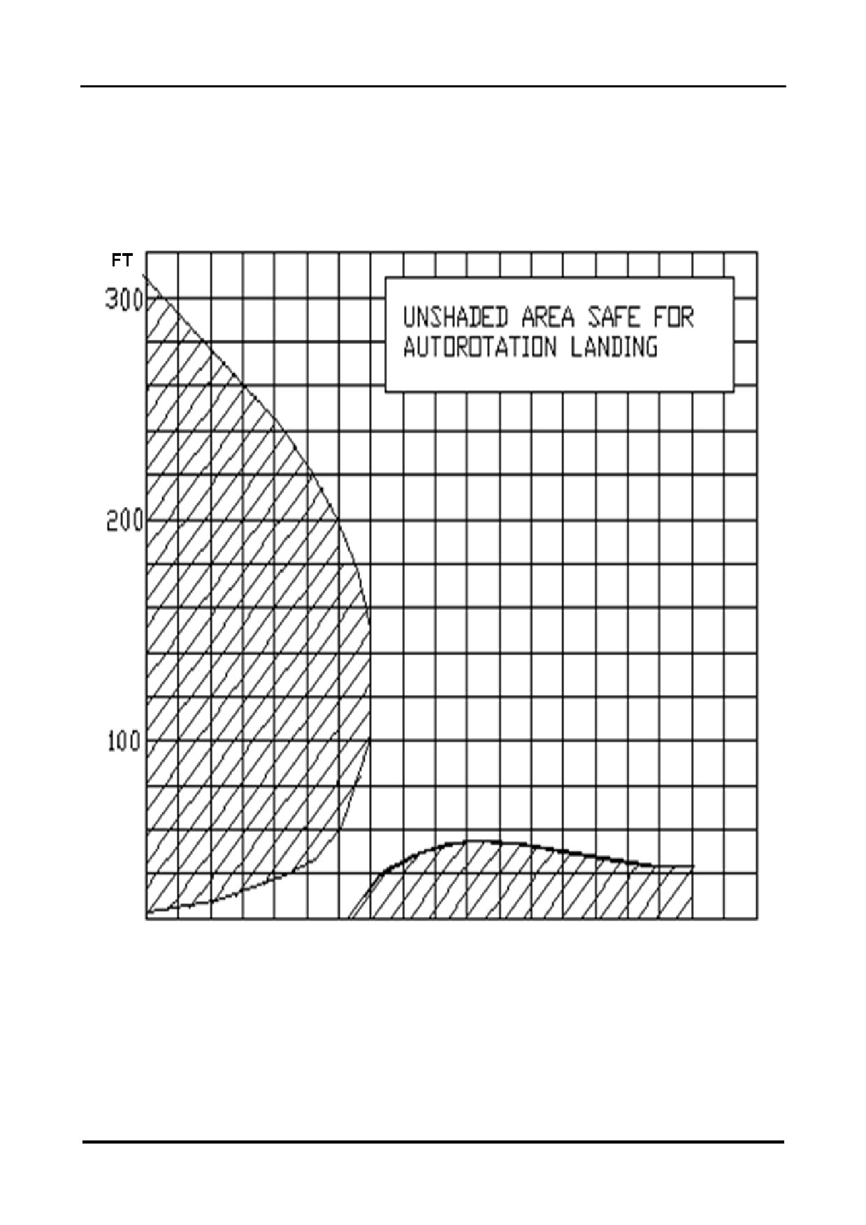
CH-7 HELISPORT S.R.L
CH-77 RANABOT
SECTION5 — PERFORMANCE
5.6 HEIGHT / VELOCITY DIAGRAM
0
17
29
40
52
63
75
86
98
109
mph
28.01.2022 ENG
Page 71 of 138

CH-7 HELISPORT S.R.L
CH-77 RANABOT
SECTION5 — PERFORMANCE
5.7 ENGINE PERFORMANCE DIAGRAMS
EPAPOWER SA-R917Ti - ENGINE PERFORMANCE @5500 RPM
MAP
POWER
POWER
TORQUE
FUEL FLOW
(inHg)
(kW)
(hp)
(Nm)
(l/h)
10
8
11
14
6,0
15
22
30
38
11,0
20
43
58
75
16,0
25
55
75
95
21,0
26
58
79
101
21,0
27
62
84
108
22,0
28
64
87
111
24,0
29
67
91
116
25,0
30
70
95
122
26,0
31
73
99
127
27,0
32
75
102
130
28,0
33
77
105
134
30,0
34
80
109
139
31,5
35
84
114
146
32,0
36
86
117
149
34,0
37
89
121
155
35,0
38
91
124
158
36,0
39
95
129
165
37,0
40
98
133
170
38,0
41
100
136
174
39,0
28.01.2022 ENG
Page 72 of 138
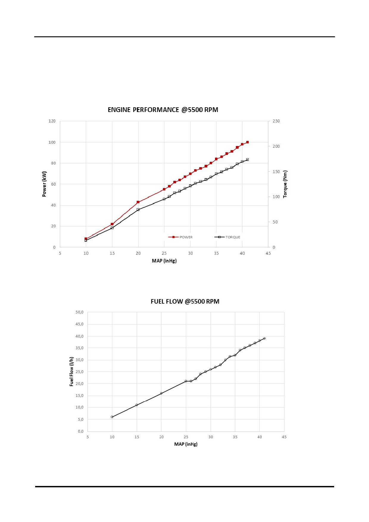
CH-7 HELISPORT S.R.L
CH-77 RANABOT
SECTION 5 — PERFORMANCE
5.7 ENGINE PERFORMANCE DIAGRAMS(CONT)
28.01.2022 ENG
Page 73 of 138

CH-7 HELISPORT S.R.L
CH-77 RANABOT
SECTION 5 — PERFORMANCE
INTENTIONALLY BLANK
28.01.2022 ENG
Page 74 of 138

CH-7 HELISPORT S.R.L
CH-77 RANABOT
SECTION6 — WEIGHT AND BALANCE
CONTENTS SECTION 6
6.1 GENERAL
76
6.2 HELICOPTER WEIGHING PROCEDURES
77
6.3 WEIGHT AND BALANCE EXAMPLES
79
6.3.1 Example 1
79
6.3.2 Example 2
80
6.3.3 Example 3
80
6.3.4 Example 4
81
6.3.5 Example 5
81
28.01.2022 ENG
Page 75 of 138

CH-7 HELISPORT S.R.L
CH-77 RANABOT
SECTION 6 — WEIGHT AND BALANCE
6.1 GENERAL
Flight is only permitted within the weight and balance limits specified in section« 2.8 CENTRE
OF GRAVITY LIMITATIONS ». Loading outside these limits can result in insufficient control
travel to safely control flight.
The longitudinal weight and balance limits specified in section « 2.8 CENTRE OF GRAVITY
LIMITATIONS » are expressed in this section as total moments. These total moments may be
determined using the method described in section
« 6.3 WEIGHT AND BALANCE
EXAMPLES ».
CAUTION: The fuel tanks are not located at the centre of gravity of the helicopter.
As a consequence, the CoG will move during flight as fuel is consumed.
Always determine the safe loading with empty fuel as well as with take-off fuel
quantity. The amount of fuel that may be offloaded to compensate for a greater
payload is limited by the forward CoG location with empty fuel.
28.01.2022 ENG
Page 76 of 138

CH-7 HELISPORT S.R.L
CH-77 RANABOT
SECTION6 — WEIGHT AND BALANCE
6.2 HELICOPTER WEIGHING PROCEDURES
PREPARATION OF THE AIRCRAFT
1
Drain all usable fuel.
2
Fill engine oil and transmission oil to maximum levels.
3
Ensure that all equipment corresponding to the basic empty weight configuration is
correctly installed.
4
Remove any foreign items not included in the basic empty weight configuration (such as
maps, tools or rags).
WEIGHING AND BALANCING THE AIRCRAFT
1
Raise the aircraft and place a 250 kg capacity scale under each skid.
2
Lower the aircraft to rest on the scales. Move the scales so that the aircraft is perfectly
balanced before releasing the tail boom. Ensure the aircraft is laterally horizontal by
placing a level between the manoeuvring wheel supports.
3
The aircraft empty weight corresponds to the sum of the weights indicated by the two
scales.
4
Lower the tail boom, remove the two scales and place a 5 cm diameter steel tube under
the two skids.
5
Balance the aircraft is on the tube while the aircraft remains laterally horizontal and the
tube remains perpendicular to the mid-line between the skids. Mark the point of balance
on a skid.
6
Mark also on this skid the point of intersection of the vertical plane that is both
perpendicular to the mid-line between the two skids and passes through the centre of the
main rotor disc.
7
Given that the reference plane is parallel to and 254 cm forward of the plane defined in
paragraph 6, Measure the distance from the reference plane to the point of balance
marked on the skid. This distance corresponds to the arm of the centre of gravity of the
empty aircraft.
28.01.2022 ENG
Page 77 of 138

CH-7 HELISPORT S.R.L
CH-77 RANABOT
SECTION6 — WEIGHT AND BALANCE
6.2 HELICOPTER WEIGHING PROCEDURES (CONT)
8
Use the table below to calculate the longitudinal and lateral positions of the CoG of the
aircraft in its flight configuration both with take-off fuel weight and with tanks empty.
a)
In each of the lighter blue cells, enter the weight of the corresponding item. If either
door is removed, enter the corresponding weight as a negative value.
b)
In each of the darker blue cells, enter the sum of all of the lighter blue cells in the
table found above it. Ensure the higher of these values is less than the MTOW.
c)
In each of the grey cells enter the CoG arm determined in paragraph 7 above.
d)
In each of the lighter pink cells, enter the product of the weight and the longitudinal
arm of the corresponding item.
e)
In each of the darker pink cells, enter the sum of all of the lighter pink cells in the
table found above it.
f)
In each of the lighter orange cells, enter the product of the weight and the lateral arm
of the corresponding item.
g)
In each of the darker orange cells, enter the sum of all of the lighter orange cells in
the table found above it.
h)
In each of the lighter green cells, enter the longitudinal arm, which is calculated by
dividing the value in the darker pink cell to its right by the value in the darker blue cell
to its left. Ensure both these values lie within the envelope defined in section « 2.8
CENTRE OF GRAVITY LIMITATIONS »
i)
In each of the darker green cells, enter the lateral arm, which is calculated by dividing
the value in the darker orange cell to its right by the value in the darker blue cell to its
left. Ensure both these values lie within the envelope defined in section
« 2.8
CENTRE OF GRAVITY LIMITATIONS »
Longitudinal
Longitudinal
Lateral
Weight
Lateral arm
Item
arm STA
moment
moment
(kg)
BL (mm)
(mm)
(kgmm)
(kgmm)
Right skid scale indication
802.5
Left skid scale indication
-802.5
Right door (-3,5 kg if removed)
2,020
560
Left door (-3,5 kg if removed)
2,020
-560
Pilot (Right hand seat)
1,985
260
Passenger (Left hand seat)
1,985
-260
Non usable fuel
2,452
-350
Weight & arms (no fuel)
Fuel in main tank
2,452
-350
Fuel in auxiliary tank
2,452
350
Weight & arms (with fuel)
28.01.2022 ENG
Page 78 of 138
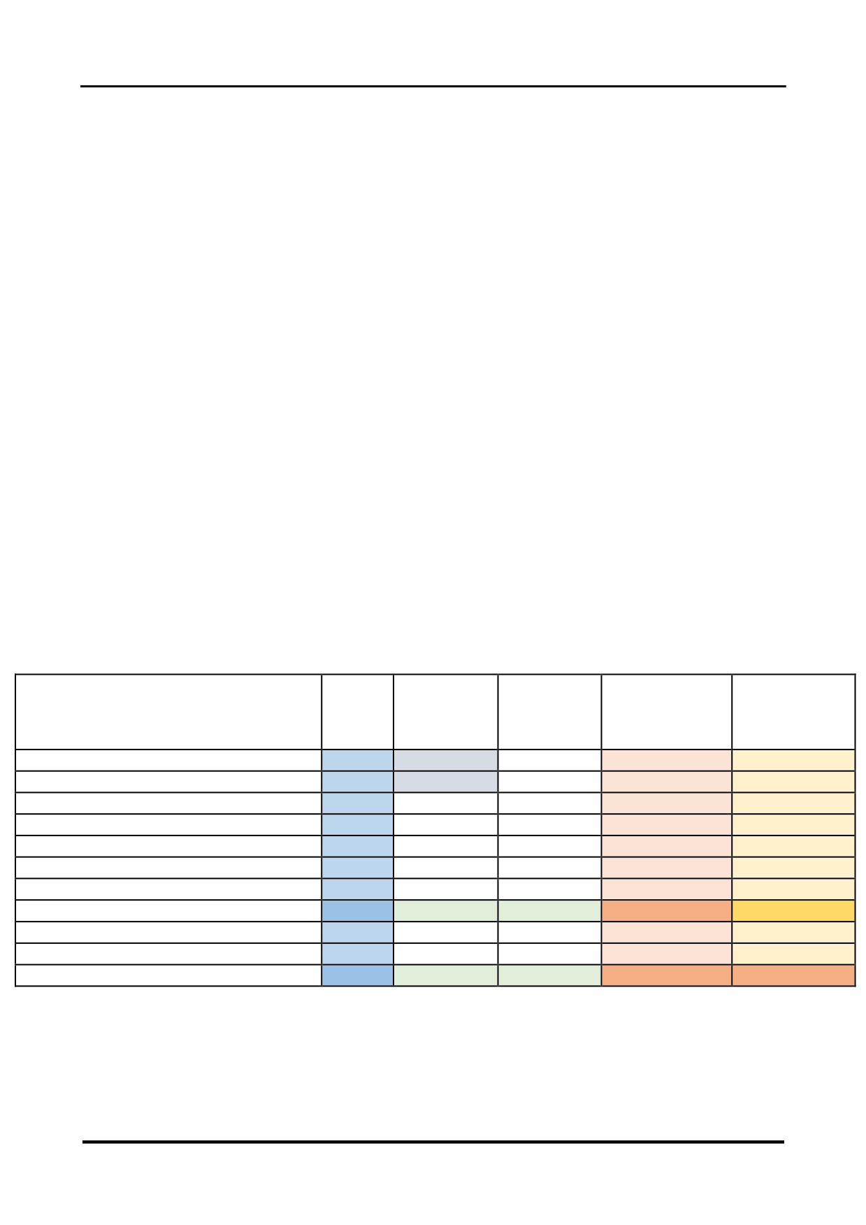
CH-7 HELISPORT S.R.L
CH-77 RANABOT
SECTION 6 — WEIGHT AND BALANCE
6.3 WEIGHT AND BALANCE EXAMPLES
Moment:
Product of the weight and the arm.
Longitudinal arm:
Horizontal distance to the centre of gravity of the item
measured from the reference datum (2.54 m forward of
the main rotor centre.)
Lateral arm:
Horizontal distance to the centre of gravity of the item
measured from the vertical longitudinal plane passing
through the mid-line between the two skids. A lateral
arm towards the right of the aircraft is expressed as a
positive value and a lateral arm towards the left of the
aircraft is expressed as a negative value.
Fuel density:
0.70 kg/litre.
6.3.1 Example1 Pilot minimum solo admissible weight: 69 kg - Both doors on
Longitudinal
Lateral arm
Longitudinal
Lateral moment
Item
Weight
arm STA
BL (mm)
moment
(kgmm)
(kg)
(mm)
(kgmm)
Right skid scale indication
144,7
2.707
802,5
391.784
116.146
Left skid scale indication
144,3
2.707
-802,5
390.539
-115.777
Right door (-3,5 kg if removed)
0
2.020
560
0
0
Left door (-3,5 kg if removed)
0
2.020
-560
0
0
Pilot (Right hand seat)
69
1.985
260
136.965
17.940
Passenger (Left hand seat)
0
1.985
-260
0
0
Non usable fuel
1
2.452
-350
2.452
-350
Weight & arms (no fuel)
359
2.568
50,0
921.740
17.959
Fuel in main tank
25,0
2.452
-350
61.300
-8.750
Fuel in auxiliary tank
24,0
2.452
350
58.848
8.400
Weight & arms (with fuel)
408
2.554
43,2
1.041.888
17.609
In this example, the take-off weight is no more that the MTOW and the total longitudinal and
lateral arms both with take-off fuel and with fuel empty are within the envelope defined in
section « 2.8 CENTRE OF GRAVITY LIMITATIONS ». Flight is permitted.
28.01.2022 ENG
Page 79 of 138
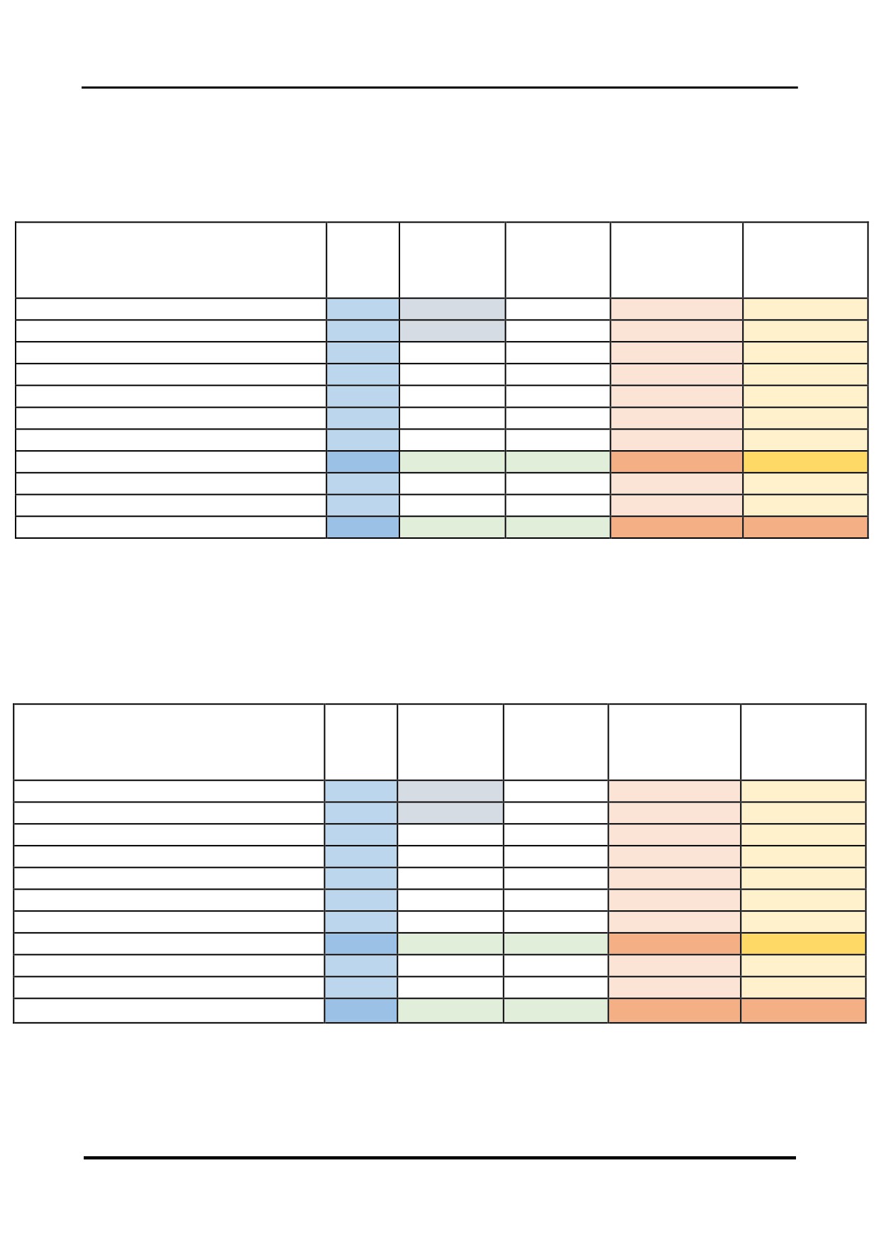
CH-7 HELISPORT S.R.L
CH-77 RANABOT
SECTION6 — WEIGHT AND BALANCE
6.3.2 Example2 Pilot maximum admissible weight: 108 kg - Both doors on
Longitudinal
Lateral arm
Longitudinal
Lateral moment
Item
Weight
arm STA
BL (mm)
moment
(kgmm)
(kg)
(mm)
(kgmm)
Right skid scale indication
144,7
2.707
802,5
391.784
116.146
Left skid scale indication
144,3
2.707
-802,5
390.539
-115.777
Right door (-3,5 kg if removed)
0
2.020
560
0
0
Left door (-3,5 kg if removed)
0
2.020
-560
0
0
Pilot (Right hand seat)
108
1.985
260
214.380
28.080
Passenger (Left hand seat)
0
1.985
-260
0
0
Non usable fuel
1
2.452
-350
2.452
-350
Weight & arms (no fuel)
398
2.510
70,6
999.155
28.099
Fuel in main tank
25,0
2.452
-350
61.300
-8.750
Fuel in auxiliary tank
24,0
2.452
350
58.848
8.400
Weight & arms (with fuel)
447
2.504
62,1
1.119.303
27.749
In this example, the take-off weight is no more that the MTOW and the total longitudinal and
lateral arms both with take-off fuel and with fuel empty are within the envelope defined in
section « 2.8 CENTRE OF GRAVITY LIMITATIONS ». Flight is permitted.
6.3.3 Example3 Limit forward CoG position - Pilot and Passenger equal weight - Both doors on -
Fuel limited by MTOW
Longitudinal
Lateral arm
Longitudinal
Lateral moment
Item
Weight
arm STA
BL (mm)
moment
(kgmm)
(kg)
(mm)
(kgmm)
Right skid scale indication
144,7
2.707
802,5
391.784
116.146
Left skid scale indication
144,3
2.707
-802,5
390.539
-115.777
Right door (-3,5 kg if removed)
0
2.020
560
0
0
Left door (-3,5 kg if removed)
0
2.020
-560
0
0
Pilot (Right hand seat)
107
1.985
260
212.395
27.820
Passenger (Left hand seat)
107
1.985
-260
212.395
-27.820
Non usable fuel
1
2.452
-350
2.452
-350
Weight & arms (no fuel)
504
2.400
0,0
1.209.565
19
Fuel in main tank
25,0
2.452
-350
61.300
-8.750
Fuel in auxiliary tank
21,0
2.452
350
51.492
7.350
Weight & arms (with fuel)
550
2.404
-2,5
1.322.357
-1.381
In this example, the take-off weight is no more that the MTOW and the total longitudinal and
lateral arms both with take-off fuel and with fuel empty are within the envelope defined in
section « 2.8 CENTRE OF GRAVITY LIMITATIONS ». Flight is permitted.
28.01.2022 ENG
Page 80 of 138
CH-7 HELISPORT S.R.L
CH-77 RANABOT
SECTION6 — WEIGHT AND BALANCE
6.3.4 Example4 Left limit CoG position - Pilot minimum admissible weight: 69 kg - Passenger
weight: 105 kg - Both doors on
Longitudinal
Lateral arm
Longitudinal
Lateral moment
Item
Weight
arm STA
BL (mm)
moment
(kgmm)
(kg)
(mm)
(kgmm)
Right skid scale indication
144,7
2.707
802,5
391.784
116.146
Left skid scale indication
144,3
2.707
-802,5
390.539
-115.777
Right door (-3,5 kg if removed)
0
2.020
560
0
0
Left door (-3,5 kg if removed)
0
2.020
-560
0
0
Pilot (Right hand seat)
69
1.985
260
136.965
17.940
Passenger (Left hand seat)
105
1.985
-260
208.425
-27.300
Non usable fuel
1
2.452
-350
2.452
-350
Weight & arms (no fuel)
464
2.436
-20,1
1.130.165
-9.341
Fuel in main tank
25,0
2.452
-350
61.300
-8.750
Fuel in auxiliary tank
24,0
2.452
350
58.848
8.400
Weight & arms (with fuel)
513
2.437
-18,9
1.250.313
-9.691
In this example, the take-off weight is no more that the MTOW and the total longitudinal arms
are within the envelope defined in section « 2.8 CENTRE OF GRAVITY LIMITATIONS
».However, the total lateral arm will fall outside the envelope as fuel is consumed. Flight is not
permitted. Removable weight may be required in the compartment on the right side of the pilot
or remove the left door
6.3.5 Example5 Pilot minimum solo admissible weight: 69 kg - Both doors removed
Longitudinal
Lateral arm
Longitudinal
Lateral moment
Item
Weight
arm STA
BL (mm)
moment
(kgmm)
(kg)
(mm)
(kgmm)
Right skid scale indication
144,7
2.707
802,5
391.784
116.146
Left skid scale indication
144,3
2.707
-802,5
390.539
-115.777
Right door (-3,5 kg if removed)
-3,5
2.020
560
-7.070
-1.960
Left door (-3,5 kg if removed)
-3,5
2.020
-560
-7.070
1.960
Pilot (Right hand seat)
69
1.985
260
136.965
17.940
Passenger (Left hand seat)
0
1.985
-260
0
0
Non usable fuel
1
2.452
-350
2.452
-350
Weight & arms (no fuel)
352
2.578
51,0
907.600
17.959
Fuel in main tank
25,0
2.452
-350
61.300
-8.750
Fuel in auxiliary tank
24,0
2.452
350
58.848
8.400
Weight & arms (with fuel)
401
2.563
43,9
1.027.748
17.609
In this example, the take-off weight is no more that the MTOW and the total longitudinal arms
are within the envelope defined in section « 2.8 CENTRE OF GRAVITY LIMITATIONS
».However, the total lateral arm will fall outside the envelope as fuel is consumed. Flight is not
permitted. Re Install one door ,left or right door or you may need a removable weight under the
passenger feet mat.
28.01.2022 ENG
Page 81 of 138

CH-7 HELISPORT S.R.L
CH-77 RANABOT
SECTION6 — WEIGHT AND BALANCE
INTENTIONALLY BLANK
28.01.2022 ENG
Page 82 of 138

CH-7 HELISPORT S.R.L
CH-77 RANABOT
SECTION7 — OPERATIONS ANDMAINTENANCE
CONTENTS SECTION 7
7.1 GENERAL
84
7.2 REQUIRED DOCUMENTS
85
7.3 REQUIRED INSPECTIONS AND MAINTENANCE
86
7.4 PILOT SAFETY TRAINING
87
7.4.1 Helisport Safety Course
87
7.4.2 Ranabot Left Seat instructor Pilot Course
87
7.5 GROUND HANDLING
88
7.5.1 Introduction
88
7.5.2 Installing the Standard Wheels
88
7.5.3 Installing the Optional Long Arm Wheels
88
7.5.4 Moving the Helicopter
89
7.5.5 Transport on a Trailer
89
7.6 PARKING
90
7.7 CLEANING
90
7.8 CHECK-LISTS
91
28.01.2022 ENG
Page 83 of 138

CH-7 HELISPORT S.R.L
CH-77 RANABOT
SECTION7 — OPERATIONS ANDMAINTENANCE
7.1 GENERAL
This section contains recommended procedures for operation, handling and maintenance of
the helicopter.
The owner and the operator must remain in close contact with an approved distributor in order
to remain permanently informed of the latest experience and advice specific to the aircraft.
CH7 HELISPORT S.r.l. holds the owner and the operator of the helicopter responsible for its
maintenance. The owner and the operator must ensure that the maintenance is performed by
suitably qualified and experienced individuals and in accordance with all publications issued by
CH7 HELISPORT S.r.l.
All limitations, procedures, safety practices, hour limits and time limits, servicing and
maintenance requirements specified in this manual are to be considered obligatory.
28.01.2022 ENG
Page 84 of 138

CH-7 HELISPORT S.R.L
CH-77 RANABOT
SECTION7 — OPERATIONS ANDMAINTENANCE
7.2 REQUIRED DOCUMENTS
The following documents must be carried on board the aircraft at all times.
1
Any documents (such as registration, airworthiness, identification and insurance
documents)that are legally required by the country of registration.
2
Aircraft Log Book
3
Pilot’s Operating Handbook
4
Weight and Balance Schedule
5
Check-list
The following documents must be kept available for consultation by the pilot before flight.
1
Maintenance Manual Hand book
2
Maintenance Log
28.01.2022 ENG
Page 85 of 138

CH-7 HELISPORT S.R.L
CH-77 RANABOT
SECTION7 — OPERATIONS ANDMAINTENANCE
7.3 REQUIRED INSPECTIONS AND MAINTENANCE
CH-7 HELISPORT S.r.l. requires the following inspections and maintenance:
1
Complete inspection, rectification work as required and initial main and tail rotor tracking
and balancing and other adjustments before the first flight of every newly assembled CH-
77 Ranabot, as specified in the latest version of the maintenance manual, followed by
test flights by a pilot approved by CH-7 HELISPORT S.r.l. This procedure must be
performed by an approved agent of CH-7 HELISPORT S.r.l.
2
Daily Inspection as described in section « 4.2 DAILY INSPECTIONS».This inspection
must be performed by the pilot after having received training organised by an approved
agent of CH-7 HELISPORT S.r.l.
3
Maintenance after only the first 25 hours of flight as specified in the latest version of the
maintenance manual. This maintenance may be performed by the owner and/or operator
after having received training organised by an approved agent of CH-7 HELISPORT S.r.l.
4
Maintenance after each 50 hours of flight as specified in the latest version of the
maintenance manual. This maintenance may be performed by the owner and/or operator
after having received training organised by an approved agent of CH-7 HELISPORT S.r.l.
5
Maintenance after each 100 hours of flight as specified in the latest version of the
maintenance manual. This maintenance must be performed by an approved agent of
CH-7 HELISPORT S.r.l.
6
Maintenance every 12 months as specified in the latest version of the maintenance
manual. This maintenance must be performed by an approved agent of CH-7
HELISPORT S.r.l.
7 Maintenance 12 Years as specified in the latest version of the maintenance manual. This
maintenance must be performed by an approved agent of CH-7 HELISPORT S.r.l.
28.01.2022 ENG
Page 86 of 138

CH-7 HELISPORT S.R.L
CH-77 RANABOT
SECTION 7 — OPERATIONS AND MAINTENANCE
7.4 PILOT SAFETY TRAINING
7.4.1 Helisport Safety Course
In order to reduce the number of accidents that are mainly caused by pilot error, the FAA
published a document SFAR73 that addresses specific characteristics inherent to the
operation of certain light two bladed helicopters. These characteristics include potential, kinetic
and rotor energy management, mast bumping, rotor stall, dangers due to low rotor speeds,
and dangers due to low or negative g-forces.
The CH-77Ranabot is an example of this type of helicopter, and CH-7 HELISPORT S.r.l.
considers that the terms of SFAR73 applies to all versions of the CH-77Ranabot.
Before assuming the functions of aircraft commander, each pilot must have completed training
that covers all of the themes specified in SFAR73, addressing the particular characteristics of
the CH-77 Ranabot.
Accordingly, CH-7 HELISPORT S.r.l. requires that all pilots acting as aircraft commander hold
a certificate of successful completion of the “Helisport Safety Course” given by a training
organisation approved byCH-7 HELISPORT S.r.l. This certificate has a validity of 2 years. (See
per section 2.9 Operation Limitation )
7.4.2 Ranabot Left Seat Instructor Pilot Course
Normal flight configuration is that the pilot and flight commander occupies the right hand seat
and the passenger occupies the left hand seat.(solo fly only right seat)
In order to exercise the functions of flight commander from the left hand seat, the occupant
must hold a certificate of successful completion of the “Ranabot Left Seat Pilot Instructor
Course” given by a training organisation approved by CH-7 HELISPORT S.r.l. This certificate
has a validity of 2 years. (See per section 2.9 Operation Limitation)
28.01.2022 ENG
Page 87 of 138

CH-7 HELISPORT S.R.L
CH-77 RANABOT
SECTION7 — OPERATIONS ANDMAINTENANCE
7.5GROUND HANDLING
7.5.1 Introduction
The operator must be familiar with the correct procedures for ground handling before moving
the helicopter or transporting it on a trailer, otherwise the aircraft could suffer serious damage.
7.5.2 Using the Standard Wheels
The standard wheels are designed for moving the aircraft on a hard smooth surface, but are
not appropriate for use on grass. Before mounting these wheels on the skids check the tail is
clear of any obstacle and that the canopy is latched. While mounting the standard wheels the
aircraft can pivot suddenly onto the tail and the tail rotor guard can strike the ground.
7.5.3 Using the Optional Long Arm Wheels
The optional long arm wheels are designed for moving the aircraft on all surfaces. Before
mounting these wheels on the skids check the tail is clear of any obstacle and that the canopy
is latched. While mounting the standard wheels the aircraft can pivot suddenly onto the tail and
the tail rotor guard can strike the ground.
28.01.2022 ENG
Page 88 of 138

CH-7 HELISPORT S.R.L
CH-77 RANABOT
SECTION 7 — OPERATIONS ANDMAINTENANCE
7.5.4 Moving the Helicopter
The operator may follow one of the two following procedures to move the helicopter:
1
Stand next to the tail boom and move the helicopter by holding the tail boom support
attachment collar.
2
Stand behind the tail rotor and move the helicopter by holding the tail gearbox with one
hand and the tail rotor guard with the other.
CAUTION:
Do not push on either of the two tail boom supports.
7.5.5 Transport on a Trailer
The trailer must be designed for loads in the order of 300 kg. Trailers designed for cars have
stiffer suspension matched for much higher loads, which can inflict unacceptable stresses on
the helicopter structure. The helicopter must be transported with the nose in the direction of
travel. The trailer must be equipped with a support for the forward blade. The optional support
available from CH-7 HELISPORT S.r.l. must be used to support the aft blade. Secure the
blades with an angle of 2° above the horizontal and with the tail rotor vertical. The supports
must be attached at no more that 50 cm from the blade tips and must not contact the trim tabs
(if fitted). Secure the helicopter to the trailer by the skids near each undercarriage leg. set the
tail rotor in vertical position ,no latched the tail rotor with any type of lock, leave the articulation
hinge free.
CAUTION:
1 Never transport the helicopter by vehicle without blade
supports correctly installed. If necessary, remove the blades.
(Refer to the construction manual).
2 Never transport the helicopter by vehicle with the helicopter
covers in place. The relative wind can cause the covers to
damage the windscreen, the paintwork and the blades.
28.01.2022 ENG
Page 89 of 138

CH-7 HELISPORT S.R.L
CH-77 RANABOT
SECTION7 — OPERATIONS ANDMAINTENANCE
7.6 PARKING
The helicopter should be parked away from the general public and preferably in a dry and
sheltered environment. If the helicopter must be parked outside in windy conditions attach the
rear blade to the tail boom with a strap. Should the helicopter be parked outside for an
extended period, use the optional protective covers. Should the helicopter be parked outside
under sun cover the instruments panel with sun shade.
7.7 CLEANING
To clean the exterior of the helicopter, use a mild well-diluted detergent in water.
Never use high-pressure water on the helicopter. To clean the engine and electrical
components, carefully use compressed air.
28.01.2022 ENG
Page 90 of 138

CH-7 HELISPORT S.R.L
CH-77 RANABOT
SECTION7 — OPERATIONS AND MAINTENANCE
7.8 CHECK-LISTS
PROCEDURE BEFORE ENGINE START
Fuel level:
Visual check
Aircraft exterior:
remove :ground wheels,rotor
ties,cowlings closed
Radio and headset:
On
Master switch:
Checklist(follow voice check list, buttons Next Back)
TCU light
On 2 secs then Off (#SA-R 914 engine only)
Previous flight time:
Check log
Warning lights: Oil, (Fuel Press #),
Gov, Gen,Alt,(Tcu*):
On (*SA-R 917 engine only) (#SA-R 914 engine only)
Seatbelts:
Fasten
Doors:
Closed and latched, emergency
release
Fuel cock:
On (SA-R 914 only)
Fuel level:
Sufficient - EMS set
Cyclic & collective frictions:
Off
Cyclic, collective and pedals:
Full and free travel
Collective:
Full down, friction on
Cyclic:
Neutral, friction on
Pedals:
Neutral
All switches:
Off
Breakers:
In
Altimeter:
Set
Frame pressure:
2 bar
28.01.2022 ENG
Page 91 of 138

CH-7 HELISPORT S.R.L
CH-77 RANABOT
SECTION7 — OPERATIONS ANDMAINTENANCE
7.8 CHECKLISTS
START UP PROCEDURE
Choke:
On if engine cold( SA-R914only)
Master:
Run
Oil, Gov, Gen,Alt,(Tcu*) warning lights:
On (*SA-R917 Ti only)
Fuel pump 1:
Check pressure
Clutch:
On, check fuel pressure increase, then off.
Throttle:
Closed
Area:
Clear
Start collective Button:
Press 5 "max, oil pressure increase
light off(1bar approximately )
Ignition Key:
« BOTH », then press Start collective Button.
Engine speed:
Idle Between 1 800 rpm and 2 650
Clutch:
On, check clutch light on, note time.
Check volts:
Check volts no below 13.0
Choke:
Off(SA-R 914 only)
Clutch light:
Off. Check running time 90 secs.
Radio:
Volume and frequency Set&Check
Transponder:
Switch to Standby (if fitted).
GPS-Traffic
Set(if fitted)
Engine oil temperature:
35°C
Engine / rotor speed:
Increase to 70% - 80%
Check circuits:
Turn key from BOTH to R
Check speed drop less than 150 rpm
Turn key from BOTH to L
Check speed drop less than 150 rpm
Ignition Key:
BOTH Set
Engine oil temperature:
50°C
Engine / rotor speed:
90%
Throttle:
Cut
Tachometer:
Needles split
Engine :
idle check no below 1800 rpm
28.01.2022 ENG
Page 92 of 138

CH-7 HELISPORT S.R.L
CH-77 RANABOT
SECTION7 — OPERATIONS ANDMAINTENANCE
7.8 CHECK-LISTS
TAKE OFF PROCEDURE
Doors:
Closed latched- 4 Red Lock
latched- doors light off
Fuel cock:
Open
Choke:
Off(SA-R 914 only)
Breakers:
Set
Warning lights:
Check on then off
Cyclic and collective frictions:
Off
Engine oil temperature:
50°C
Engine / rotor speed:
90%
Governor:
On, check 104%
Outside temperature:
Check« SECTION 5 -
PERFORMANCES »
Engine parameters:
Check
Wind:
Check
Area:
Clear
Radio:
Volume and frequency Set&Check
Transponder:
Switch to A/C/S (if fitted).
Reduce rotor speed
Check voice alarm and warning red
light on at 96 %.
Release throttle
Check 104%
READY FOR TAKE OFF
28.01.2022 ENG
Page 93 of 138

CH-7 HELISPORT S.R.L
CH-77 RANABOT
SECTION7 — OPERATIONS ANDMAINTENANCE
7.8 CHECK-LISTS
SHUT DOWN PROCEDURE
Collective:
Full down
Collective friction:
On
Governor:
Off
Engine / rotor speed:
Reduce to 70 - 80%, 1 minute.
Trims:
Neutral
Fans:
On
Engine / rotor speed:
Reduce to idle(40- 50 %)
Cyclic friction:
On
CHT and engine oil temperature: Below 90°C
Clutch:
Off, check clutch light on, note time
Ignition Key:
Turn Off after 40 secs clutch motor started
Master switch:
Check List position
Clutch light:
Off. Running time Check 100 secs.
Master switch:
Off and all Switch off
Flight time
Note in log.
28.01.2022 ENG
Page 94 of 138

CH-7 HELISPORT S.R.L
CH-77 RANABOT
SECTION8 — SAFETY NOTICES
CONTENTS SECTION 8
8.1
GENERAL
97
8.2
DYNAMIC ROLLOVER
98
8.3
FATAL ACCIDENTS DUE TO ROTOR STALL (LOW ROTOR SPEED)
99
8.4
LOW G PUSHOVERS ARE EXTREMELY DANGEROUS
100
8.5
DO NOT ATTACH OBJECTS TO THE SKIDS
101
8.6
FUEL EXHAUSTION CAN BE FATAL
102
8.7
POWER LINES ARE DEADLY
103
8.8
NEVER EXIT THE HELICOPTER WITH THE ENGINE RUNNING
104
8.9
HOLD CONTROLS WHEN BOARDING PASSENGERS
105
8.10
NEVER LAND IN TALL DRY GRASS
106
8.11
LOSS OF VISIBILITY CAN BE FATAL
107
8.12
OVERCONFIDENCE PREVAILS IN ACCIDENTS
108
8.13
FLYING LOW OVER WATER IS DANGEROUS
109
8.14
DEMONSTRATION OR INITIAL TRAINING FLIGHTS
110
8.15
REDUCE VERTICAL SPEED BEFORE REDUCING AIRSPEED
111
8.16
THE ROTORS CAN KILL
112
8.17
ROTOR STALL CAN BE FATAL
113
8.18
NIGHT FLGHT IN POOR WEATHER CONDITIONS
115
28.01.2022 ENG
Page 95 of 138

CH-7 HELISPORT S.R.L
CH-77 RANABOT
SECTION8 — SAFETY NOTICES
CONTENTS SECTION 8 (cont)
8.19 SURPRISE THROTTLE CHOPS CAN BE DEADLY
116
8.20 LISTEN FOR IMPENDNG BEARING FAILURE
117
8.21 AEROPLANE PILOTS FLYING HELICOPTERS
118
8.22 LOOSE OBJECTS CAN BE FATAL
119
8.23 HIGH WINDS AND TURBULENCE
120
8.24 RISKS IN SURVEY AND PHOTO FLIGHTS
121
8.25 FLYING NEAR RADIO TRANSMISSION TOWERS
122
8.26 EXCEEDING LIMITATIONS CAN BE FATAL
123
8.27 PRACTISE AUTOROTATIONS CAUSE MANY ACCIDENTS
124
8.28 UNUSUAL VIBRATION - POSSIBLE BLADE CRACKS
125
8.29 FIRE AFTER AN ACCIDENT
126
8.30 PILOT DISTRACTION
127
8.31 UNANTICIPATED YAW
128
28.01.2022 ENG
Page 96 of 138

CH-7 HELISPORT S.R.L
CH-77 RANABOT
SECTION8 — SAFETY NOTICES
8.1 GENERAL
The Safety Notices contained within this section have been issued as a result of various
incidents and accidents related to light helicopters.
28.01.2022 ENG
Page 97 of 138

CH-7 HELISPORT S.R.L
CH-77 RANABOT
SECTION8 — SAFETY NOTICES
8.2 DYNAMIC ROLLOVER
A dynamic rollover can occur whenever the landing gear contacts a fixed object, forcing the
aircraft to pivot about the object instead of about its own centre of gravity. The fixed object can
be any obstacle or surface which prevents the skid from moving sideways.
Once started, dynamic rollover cannot be stopped by application of opposite cyclic alone. For
example, assume the right skid contacts an object and becomes the pivot point while the
helicopter starts rolling to the right.Even with full left cyclic applied, the main rotor thrust vector
will still pass on the left side of the pivot point and produce a rolling moment to the right instead
of to the left. The thrust vector and its moment will follow the aircraft as it continues rolling to
the right. Quickly applying down collective is the most effective way to stop a dynamic rollover.
To avoid a dynamic rollover:
1
Always practice hovering autorotations into the wind and never when the wind is gusty
or over 10 knots.
2
Never hover close to fences, sprinklers, bushes, runway lights or other obstacles a skid
could catch on.
3
Always use a two-step liftoff. Raise the collective just enough to be light on the skids
and feel for equilibrium, then gently lift the helicopter into the air.
4
Do not practice hovering manoeuvres close to the ground.
5
Keep the skids at least five feet above the ground when practising sideward or rearward
flight.
28.01.2022 ENG
Page 98 of 138

CH-7 HELISPORT S.R.L
CH-77 RANABOT
SECTION8 — SAFETY NOTICES
8.3 FATAL ACCIDENTS DUE TO ROTOR STALL (LOW RPM)
A primary cause of fatal accidents in light helicopters is failure to maintain rotor speed. To
avoid this, every pilot must have his reflexes conditioned so he will instantly add throttle and
lower collective to maintain rotor speed in any emergency.
Even when going down into rough terrain, trees, wires or water, he must force himself to lower
the collective to maintain rotor speed until just before impact. The aircraft may roll over and be
severely damaged, but the occupants have an excellent chance of walking away from it
without injury.
Power available from the engine is directly proportional to rotor speed. If the rotor speed drops
by 10%, there will be 10% less power. With less power, the helicopter will start to settle, and if
the collective is raised to stop it from settling, the rotor speed will be pulled down even lower,
causing the aircraft to settle even faster. If the pilot not only fails to lower collective, but instead
pulls up on the collective to keep the aircraftfrom going down, the rotor will stall almost
immediately. When it stalls, the blades will either “blow back” and cut off the tailcone or it will
just stop flying, allowing the helicopter to fall at an extreme rate. In either case, the resulting
crash is likely to be fatal.
No matter what causes the low rotor speed, the pilot must first roll on throttle and lower the
collective simultaneously to recover rotor speed before investigating the problem. It must be a
conditioned reflex. In forward flight, applying aft cyclic to bleed off airspeed will also help
recover lost rotor speed.
28.01.2022 ENG
Page 99 of 138

CH-7 HELISPORT S.R.L
CH-77 RANABOT
SECTION8 — SAFETY NOTICES
8.4 LOW G PUSHOVERS ARE EXTREMELY DANGEROUS
Pushing the cyclic forward following a pull-up or rapid climb, or even from level flight, produces
a low-G (or weightless) flight condition.
If the helicopter is still pitching forward when the pilot applies aft cyclic to reload the rotor, the
rotor disc may tilt aft relative to the fuselage before it is reloaded. The main rotor torque
reaction will then combine with tail rotor thrust to produce a powerful right rolling moment on
the fuselage. With no lift from the rotor, there is no lateral control to stop the rapid right roll and
mast bumping can occur. Severe in-flight mast bumping usually results in main rotor shaft
separation and/or rotor blade contact with the fuselage.
The rotor must be reloaded before lateral cyclic can stop the right roll. To reload the rotor,
apply an immediate gentle aft cyclic, but avoid any large aft cyclic inputs. (The low-G which
occurs during a rapid autorotation entry is not a problem because lowering collective reduces
both rotor lift and rotor torque at the same time.)
Never attempt to demonstrate or experiment with low-G manoeuvres, regardless of your skill
or experience level. Even highly experienced test pilots have been killed investigating the low-
G flight condition. Always use great care to avoid any manoeuvre which could result in a low-G
condition. Low-G mast bumping accidents are almost always fatal.
NEVER PERFORM A LOW-G PUSHOVER
28.01.2022 ENG
Page 100 of 138

CH-7 HELISPORT S.R.L
CH-77 RANABOT
SECTION8 — SAFETY NOTICES
8.5 DO NOT ATTACH OBJECTS TO THE SKIDS
The landing gear has cracked on several helicopters when the pilot attempted to carry an
external load strapped to the landing gear skids. The landing gear is optimized to take high
“up” loads. Consequently, it has very low strength in the opposite or “down”direction. Also,
even a small weight attached to the landing gear may change the natural frequency enough to
cause high loads due to inflight vibration. Do not attempt to carry any external load or object
attached to the landing gear.
28.01.2022 ENG
Page 101 of 138

CH-7 HELISPORT S.R.L
CH-77 RANABOT
SECTION8 — SAFETY NOTICES
8.6 FUEL EXHAUTION CAN BE FATAL
Many pilots underestimate the seriousness of fuel exhaustion. Running out of fuel is the same
as a sudden total engine or drive system failure.
When that occurs, the pilot must immediately enter autorotation and prepare for a forced
landing(see section « 3.1 POWER FAILURE »). If autorotation is not entered immediately,
the rotor speed will rapidly decay, the rotor will stall, and the results will probably be fatal.
Serious or fatal accidents have occurred as a result of fuel exhaustion.
To ensure this does not happen to you, observe the following precautions:
1
Never rely solely on the EMS or the low fuel warning light. These electromechanical
devices have questionable reliability in any airplane or helicopter. Always record the
hourmeter reading each time the fuel tanks are filled.
2
During your preflight:
a Check the fuel level in the tanks visually.
b Ensure the fuel caps are tight.
c Drain a small quantity of fuel from each tank and the gascolator to check for water or
other contamination.
3
Before takeoff:
a Ensure that the fuel valve is full on.
b Plan your next fuel stop so you will have at least 20 minutes of fuel remaining.
4
In flight:
a Continually check both hourmeter and the EMS fuel gauge.
Lf either indicates low fuel, land immediately.
b NEVER allow the fuel quantity to become so low in flight that the low fuel warning
light comes on.
28.01.2022 ENG
Page 102 of 138

CH-7 HELISPORT S.R.L
CH-77 RANABOT
SECTION8 — SAFETY NOTICES
8.7 POWER LINES ARE DEADLY
Flying into wires, cables, and other objects is by far the number one cause of fatal accidents in
helicopters. Pilots must constantly be on the alert for this very real hazard.
1
Watch for the pylons; you will not see the wires in time.
2
Fly directly over the pylons when crossing power lines.
3
Allow for the smaller, usually invisible, grounding wire(s) which are well above the larger
more visible wires.
4
Constantly scan the higher terrain on either side of your flight path for pylons.
5
Always maintain at least 500 ft AGL except during take-off and landing. By always flying
above 500 ft AGL, you can virtually eliminate the primary cause of fatal accidents.
28.01.2022 ENG
Page 103 of 138

CH-7 HELISPORT S.R.L
CH-77 RANABOT
SECTION8 — SAFETY NOTICES
8.8 NEVER EXIT THE HELICOPTER WITH THE ENGINE
RUNNING
Several accidents have occurred when pilots momentarily left their helicopters unattended with
the engine running and rotors turning. The collective can creep up, increasing both pitch and
throttle, allowing the helicopter to lift off or roll out of control.
28.01.2022 ENG
Page 104 of 138

CH-7 HELISPORT S.R.L
CH-77 RANABOT
SECTION8 — SAFETY NOTICES
8.9 HOLD CONTROLS WHEN BOARDING PASSENGERS
It is important to firmly grip both cyclic and throttle while loading or unloading passengers with
the engine running in case they inadvertently bump the controls or slide across the throttle,
rolling it open.
28.01.2022 ENG
Page 105 of 138

CH-7 HELISPORT S.R.L
CH-77 RANABOT
SECTION8 — SAFETY NOTICES
8.10 NEVER LAND IN TALL DRY GRASS
The engine exhaust is very hot and can easily ignite tall grass or brush.
Helicopters have been completely destroyed by fire after a normal landing in tall grass.
28.01.2022 ENG
Page 106 of 138

CH-7 HELISPORT S.R.L
CH-77 RANABOT
SECTION8 — SAFETY NOTICES
8.11 LOSS OF VISIBILITY CAN BE FATAL
Flying a helicopter in obscured visibility due to fog, snow, low ceiling, or even a dark night can
be fatal. Helicopters have less inherent stability and much faster roll and pitch rates than
aeroplanes. Loss of the pilot’s outside visual references, even for a moment, can result in
disorientation, wrong control inputs, and an uncontrolled crash. This type of situation is likely to
occur when a pilot attempts to fly through a partially obscured area and realizes too late that
he is losing visibility.
He loses control of the helicopter when he attempts a turn to regain visibility but is unable to
complete the turn without visual references.
You must take corrective action before visibility is lost! Remember, unlike the aeroplane, the
unique capability of the helicopter allows you to land and use alternative transport during bad
weather, provided you have the good judgement and necessary willpower to make the correct
decision.
28.01.2022 ENG
Page 107 of 138

CH-7 HELISPORT S.R.L
CH-77 RANABOT
SECTION8 — SAFETY NOTICES
8.12 OVERCONFIDENCE PREVAILS IN ACCIDENTS
A personal trait most often found in pilots having serious accidents is overconfidence.
High-time fixed-wing pilots transitioning into helicopters and private owners are particularly
susceptible. Aeroplane pilots feel confident and relaxed in the air, but have not yet developed
the control feel, coordination, and sensitivity demanded by a helicopter.
Private owners have no boss and can fly without discipline, enforced rules, or periodic flight
checks and critique by a chief pilot. A private owner must depend on self-discipline, which is
sometimes forgotten.
When flown properly and conservatively, helicopters are potentially the safest aircraft built. But
helicopters are also probably the least forgiving. They must always be flown defensively. The
pilot should allow himself a greater safety margin than he thinks will be necessary, just in case.
28.01.2022 ENG
Page 108 of 138

CH-7 HELISPORT S.R.L
CH-77 RANABOT
SECTION8 — SAFETY NOTICES
8.13 FLYING LOW OVER WATER IS DANGEROUS
Many helicopter accidents have occurred while manoeuvring low over water.
Many pilots do not realize their loss of depth perception when flying over water. Flying over
calm glassy water is particularly dangerous, but even choppy water, with its constantly varying
surface, interferes with normal depth perception and may cause a pilot to misjudge his height
above the water.
MAINTAIN 500 FT AGL WHENEVER POSSIBLE AND AVOID MANOEUVRES OVER
WATER BELOW 200 FT AGL.
28.01.2022 ENG
Page 109 of 138

CH-7 HELISPORT S.R.L
CH-77 RANABOT
SECTION8 — SAFETY NOTICES
8.14 DEMONSTRATION OR INITIAL TRAINING FLIGHTS
A disproportionate number of fatal and non-fatal accidents occur during demonstration or initial
training flights. The accidents occur because individuals other than the pilot are allowed to
manipulate the controls without being properly prepared or indoctrinated.
lf a student begins to lose control of the aircraft, an experienced flight instructor can easily
regain control provided the student does not make any large or abrupt control movements. lf,
however, the student becomes momentarily confused and makes a sudden large control input
in the wrong direction, even the most experienced instructor may not be able to recover
control. Instructors are usually prepared to handle the situation where the student loses control
and does nothing, but they are seldom prepared for the student who loses control and does
the wrong thing.
Before allowing someone to touch the controls of the aircraft, they must be thoroughly
indoctrinated concerning the extreme sensitivity of the controls in a light helicopter. They must
be firmly instructed to never make a large or sudden movement with the controls. And, the
pilot-in-command must be prepared to instantly grip the controls should the student start to
make a wrong move.
28.01.2022 ENG
Page 110 of 138

CH-7 HELISPORT S.R.L
CH-77 RANABOT
SECTION8 — SAFETY NOTICES
8.15
REDUCE VERTICAL SPEED BEFORE REDUCING
AIRSPEED
Many helicopter accidents have been caused by the pilot reducing his airspeed to near zero
during an approach before reducing his rate-of-descent.
As the pilot then raises the collective and flares to stop his rate-of-descent, he flares into his
own downwash, greatly increasing the power and collective pitch required. The aircraft begins
to enter the vortex ring state (settling-with-power) and a hard landing occurs, often followed by
a rollover. This can occur during a steep approach either power-on or power-off.
This can be avoided by always reducing your rate-of-descent before reducing your airspeed. A
good rule to follow is never allow your airspeed to be less than 30 mph until the rate-
of~descent is less than 300ft/min.
28.01.2022 ENG
Page 111 of 138

CH-7 HELISPORT S.R.L
CH-77 RANABOT
SECTION8 — SAFETY NOTICES
8.16 THE ROTORS CAN KILL
Non-pilot passengers have been killed by inadvertently walking into a rotating main rotor or tail
rotor. Every possible precaution must be taken by the pilot to prevent this tragic type of
accident. The main rotor blades can easily descend below head height especially in windy
conditions, if the helicopter is parked on even a slight slope, or if the cyclic is not properly
centred. The tail rotor is just as dangerous for anyone passing near the rear of the helicopter.
The following rules should always be observed:
• Never allow anyone to approach the helicopter unless they are escorted or have been
properly instructed. If necessary, shut down and stop rotors before boarding passengers.
• Always have strobe light flashing when rotors are turning.
• Passengers must only approach the helicopter while maintaining a low crouch position.
• Instruct passengers to establish and maintain eye contact with pilot when approaching
the helicopter. (This will force them to approach only from the nose or side, never the
tail).
• Instruct passengers to leave the helicopter in full view of the pilot and move only around
the nose, never the tail.
• Be especially careful when landing away from airfields as unseen children or adults might
approach the helicopter from the rear.
28.01.2022 ENG
Page 112 of 138

CH-7 HELISPORT S.R.L
CH-77 RANABOT
SECTION8 — SAFETY NOTICES
8.17 LOW RPM ROTOR STALL CAN BE FATAL
Rotor stall due to low rotor speed causes a very high percentage of helicopter accidents, both
fatal and non-fatal. Frequently misunderstood, rotor stall is not to be confused with retreating
blade stall which occurs only at high forward speeds when stall occurs over a small portion of
the retreating blade. Retreating blade stall causes vibration and control problems, but the rotor
is still very capable of providing sufficient lift to support the weight of the helicopter.
Rotor stall, on the other hand, can occur at any airspeed and when it does, the rotor stops
producing the lift required to support the helicopter and the aircraft literally falls out of the sky.
Fortunately, rotor stall accidents usually occur close to the ground during takeoff or landing
and the helicopter falls only four or five feet. The helicopter is wrecked but the occupants
survive. However, rotor stall can also occur at higher altitudes and when it happens at heights
above 40 or 50 ft AGL it is most likely to be fatal.
Rotor stall is very similar to the stall of an aeroplane wing at low airspeeds. As the airspeed of
an aeroplane gets lower, the nose-up angle, or angle-of-attack, of the wing must be higher for
the wing to produce the lift required to support the weight of the aeroplane. At a critical angle
(about 15 degrees), the airflow over the wing will separate and stall, causing a sudden loss of
lift and a very large increase in drag.
The aeroplane pilot recovers by lowering the nose of the aeroplane to reduce the wing angle-
of-attack below stall and adds power to recover the lost airspeed.
The same thing happens during rotor stall with a helicopter except it occurs due to low rotor
speed instead of low airspeed. As the speed of the rotor reduces, the angle-of-attack of the
rotor blades must be higher to generate the lift required to support the weight of the helicopter.
Even if the collective is not raised by the pilot to provide the higher blade angle, the helicopter
will start to descend until the upward movement of air to the rotor provides the necessary
increase in blade angle-of-attack. As with the aeroplane wing, the blade airfoil will stall at a
critical angle, resulting in a sudden loss of lift and a large increase in drag. The increased drag
on the blades acts like a huge rotor brake causing the rotor speed to rapidly decrease, further
increasing the rotor stall. As the helicopter begins to fall, the upward rushing air continues to
increase the angle-of-attack on the slowly rotating blades, making recovery virtually
impossible, even with full down collective.
28.01.2022 ENG
Page 113 of 138

CH-7 HELISPORT S.R.L
CH-77 RANABOT
SECTION8 — SAFETY NOTICES
8.17 LOW RPM ROTOR STALL CAN BE FATAL (cont)
When the rotor stalls, it does not do so symmetrically because any forward airspeed of the
helicopter will produce a higher airflow on the advancing blade than on the retreating blade.
This causes the retreating blade to stall first, allowing it to dive as it goes aft while the
advancing blade is still climbing as it goes forward. The resulting low aft blade and high
forward blade become a rapid aft tilting of the rotor disc sometimes referred to as "rotor blow-
back". Also, as the helicopter begins to fall, the upward flow of air under the tail surfaces tends
to pitch the aircraft nose-down. These two effects, combined with aft cyclic by the pilot
attempting to keep the nose from dropping, will frequently allow the rotor blades to blow back
and chop off the tailboom as the stalled helicopter falls. Due to the magnitude of the forces
involved and the flexibility of rotor blades, rotor teeter stops will not prevent the boom chop.
The resulting boom chop, however, is academic, as the aircraft and its occupants are already
doomed by the stalled rotor before the chop occurs.
To prevent rotor stall and its catastrophic consequences thepilot must always do whatever is
required to maintain a safe rotor speed. It must take precedence over all other considerations,
even if it means landing in a swamp instead of trying to stretch the glide to the dry road
beyond.
Remember the power output of the engine is proportional to rotor speed and when the rotor
speed is low there is less power available from the engine with which to regain the lost rotor
speed. The power on low RPM recevery procedure of simultaneously rolling on throttle while
lowering collective must be practised until it becomes an automatic reaction to any indication
of low rotor speed. Low airspeeds combined with high sink rates must always be avoided and
full collective must never be pulled until the helicopter is within 1 ft of the ground.
28.01.2022 ENG
Page 114 of 138

CH-7 HELISPORT S.R.L
CH-77 RANABOT
SECTION8 — SAFETY NOTICES
8.18 NIGHT FLIGHT IN POOR WEATHER CONDITIONS
Many fatal accidents have occurred at night when the pilot attempted to fly in marginal weather
after dark. The fatal accident rate during night flight is many times higher than during daylight
hours.
When it is dark, the pilot cannot see wires or the bottom of clouds, nor low hanging scud or
fog. Even when he does see it, he is unable to judge its altitude because there is no horizon
for reference. He doesn’t realize it is there until he has actually flown into it and suddenly loses
his outside visual references and his ability to control the attitude of the helicopter. As
helicopters are not inherently stable and have very high roll rates, the aircraft will quickly go
out of control, resulting in a high velocity crash which is usually fatal.
Be sure you NEVER fly at night unless you have clear weather with unlimited or very high
ceilings and plenty of celestial or ground lights for reference.
28.01.2022 ENG
Page 115 of 138

CH-7 HELISPORT S.R.L
CH-77 RANABOT
SECTION8 — SAFETY NOTICES
8.19 SURPRISE THROTTLE CHOPS CAN BE DEADLY
Many flight instructors do not know how to give a student a simulated power failure safely.
They may have learned how to respond to a throttle chop themselves, but they haven't learned
how to prepare a student for a simulated power failure or how to handle a situation where the
student’s reactions are unexpected. The student may freeze on the controls, push the wrong
pedal, raise instead of lower the collective, or just do nothing. The instructor must be prepared
to handle any unexpected student reaction.
Before giving a simulated power failure, carefully prepare the student and be sure you have
flown together enough to establish that critical understanding and communication between
instructor and student. Go through the exercise together a number of times until the student’s
reactions are both correct and predictable. Never truly surprise the student. Tell him you are
going to give him a simulated power failure a few minutes before, and when you roll off the
throttle, loudly announce “power failure". The manifold pressure should be less than 26 inches
and the throttle should be rolled off smoothly, never "chopped". Follow through on all controls
and tighten the muscles in your right leg to prevent the student from pushing the wrong pedal if
he becomes confused. And always assume that you will be required to complete the
autorotation entry yourself. Never wait to see what the student does. Plan to initiate the
recovery within one second, regardless of the student’s reaction.
There have been instances when the engine has quit during simulated engine failures. As a
precaution, always perform the simulated engine failure within glide distance of a smooth open
area where you are certain you could complete a safe touch-down autorotation should it
become necessary. Also, never practice simulated powerfailures until the engine is thoroughly
warmed up. Wait until you have been flying for at least 15 to 20 minutes.
28.01.2022 ENG
Page 116 of 138

CH-7 HELISPORT S.R.L
CH-77 RANABOT
SECTION8 — SAFETY NOTICES
8.20 LISTEN FOR IMPENDING BEARING FAILURE
An impending ball or roller bearing failure is usually preceded by a noticeable increase in
noise. The noise will typically start several hours before the bearing actually fails or before
there is any increase in bearing temperature. To detect impending failure of a drive system
bearing, the pilot should uncover one ear and listen to the sound of the drive system during
start-up and shutdown. After the pilot becomes familiar with the normal sound of the drive
system, he should be able to detect the noise made by a failing bearing. The failing bearing
will produce a loud whine, rumble, growl, or siren sound. Upon hearing an unusual noise, the
pilot must immediately ground the aircraft and have the bearings thoroughly inspected by a
qualified mechanic.
Failure of a bearing in flight could result in a serious accident.
Do not rely on Telatemps to indicate impending bearing failure. A failing bearing may not run
hot enough to black out the Telatemps until it actually starts to disintegrate. This may occur
only seconds before complete failure.
28.01.2022 ENG
Page 117 of 138

CH-7 HELISPORT S.R.L
CH-77 RANABOT
SECTION8 — SAFETY NOTICES
8.21 AEROPLANE PILOTS FLYING HELICOPTERS
There have been a number of fatal accidents involving experienced pilots who have many
hours in aeroplanes but with only limited experience flying helicopters.
The ingrained reactions of an experienced aeroplanepilot can be deadly when flying a
helicopter. The aeroplanepilot may fly the helicopter well when doing normal manoeuvres
under ordinary conditions when there is time to think about the proper control response. But
when required to react suddenly under unexpected circumstances, he may revert to his
aeroplanereactions and commit a fatal error. Under those conditions, his hands and feet move
purely by reaction without conscious thought.
Those reactions may well be based on his greater experience, ie., the reactions developed
flying aeroplanes.
For example, in an aeroplanehis reaction to a warning horn (stall) would be to immediately go
forward with the stick and add power. In a helicopter, application of forward stick when the pilot
hears a horn (low RPM) would drive the rotor speed even lower and could result in rotor stall,
especially if he also "adds power" (up collective). ln less than one second the pilot could stall
his rotor, causing the helicopter to fall out of the sky.
Another example is the reaction necessary to make the aircraft go down. If the helicopter pilot
must suddenly descend to avoid a bird or another aircraft, he rapidly lowers the collective with
very little movement of the cyclic. In the same situation, the aeroplanepilot would push the
stick forward to dive. A rapid forward movement of the helicopter cyclic under these conditions
would result in a low "G" condition which could cause mast bumping, resulting in separation of
the rotor shaft or one blade striking the fuselage. A similar situation exists when terminating a
climb after a pull-up. The aeroplanepilot does it with forward stick. The helicopter pilot must
use his collective or a very gradual, gentle application of forward cyclic.
To stay alive in the helicopter, the experienced aeroplanepilot must devote considerable time
and effort to developing safe helicopter reactions. The helicopter reactions must be stronger
and take precedence over the pilot’s aeroplanereactions because everything happens faster in
a helicopter. The pilot does not have time to realize he made the wrong move, think about it,
and then correct it. lt’s too late; the rotor has already stalled or a blade has already struck the
airframe and there is no chance of recovery. To develop safe helicopter reactions, the
aeroplanepilot must practice each procedure over and over again with a competent instructor
until his hands and feet will always make the right move without requiring conscious thought.
ABOVE ALL, HE MUST NEVER ABRUPTLY PUSH THE CYCLIC STICK FORWARD.
28.01.2022 ENG
Page 118 of 138

CH-7 HELISPORT S.R.L
CH-77 RANABOT
SECTION8 — SAFETY NOTICES
8.22 LOOSE OBJECTS CAN BE FATAL
Fatal accidents have occurred due to loose objects flying out of the cabin and striking the tail
rotor.
Any object striking the tail rotor can cause failure of a tail rotor blade. Loss of or damage to a
tail rotor blade may cause a severe out-of-balance condition which can separate the tail rotor
gearbox or entire tail assembly from the tailcone, resulting in a catastrophic accident.
Accidents have also been caused by fuel caps, birds, and other objects striking the tail rotor.
Before each flight perform the following:
• Walk completely around the aircraft checking fuel cap security and tail rotor condition.
Ensure no loose objects or debris are in the vicinty of the helicopter.
• Stow or secure all loose objects in the cabin. Even with doors on, items such as charts
can be sucked out of a window.
• Instruct passengers regarding the dangers of objects striking the tail rotor. Warn them
never to throw anything from the helicopter or place items near vent doors where they
could get sucked out.
• Firmly latch all doors.
• Never fly with the left hand door removed.
(Remove only the right hand door for
ventilation.)
28.01.2022 ENG
Page 119 of 138

CH-7 HELISPORT S.R.L
CH-77 RANABOT
SECTION8 — SAFETY NOTICES
8.23 HIGH WINDS AND TURBULENCE
Flying in high winds or turbulence should be avoided but if unexpected turbulence is
encountered, the following procedures are recommended:
• Reduce airspeed to between 60 and 70 mph.
• Tighten seat belt and firmly rest right forearm on right leg to prevent unintentional control
inputs.
• Do not overcontrol. Avoid large or abrupt control movements. Allow aircraft to go with the
turbulence, then restore level flight with smooth gentle control inputs.
• Leave governor on and do not chase rotor speed or airspeed.Momentary RPM or
airspeed excursions are to be expected.
• Avoid flying on the downwind side of hills, ridges, or tall buildings where the turbulence
will probably be the most severe.
• Never fly into a blind or steep sidedvalley during high winds.
28.01.2022 ENG
Page 120 of 138

CH-7 HELISPORT S.R.L
CH-77 RANABOT
SECTION8 — SAFETY NOTICES
8.24 RISKS IN SURVEY OR PHOTO FLIGHTS
There is a misconception that aerial survey and photo flights can be flown safely by low time
pilots. This is not true. There have been numerous fatal accidents during aerial survey and
photographic flights.
Often, to please the observer or photographer, an inexperienced pilot will slow the helicopter to
less than
30 mph and then attempt to maneuver for the best viewing angle. While
manoeuvring, the pilot may lose track of airspeed and wind conditions. The helicopter can
rapidly lose translational lift and begin to settle. An inexperienced pilot may raise the collective
to stop the descent. This can reduce rotor speed thereby reducing power available and
causing an even greater descent rate and further loss of rotor speed. Rolling on throttle will
increase rotor torque but not power available due to the low rotor speed. Because tail rotor
thrust is proportional to the square of the rotor speed, if the rotor speed drops below 80%
nearly one-half of the tail rotor thrust is lost and the helicopter will rotate nose right. Suddenly
the decreasing rotor speed also causes the main rotor to stall and the helicopter falls rapidly
while continuing to rotate. The resulting impact is usually fatal.
Aerial survey and photo flights should only be conducted by well trained, experienced pilots
who:
• Have at least 500 hours pilot-in-command in helicopters and over 100 hours in the model
flown;
• Have extensive training in both low rotor speed conditions and settling-with-power
recovery techniques;
• Are willing to refuse unsafe directions from the observer or photographer and only fly the
aircraft at speeds, altitudes, and wind angles that are safe and allow good escape routes.
28.01.2022 ENG
Page 121 of 138

CH-7 HELISPORT S.R.L
CH-77 RANABOT
SECTION8 — SAFETY NOTICES
8.25 FLYING NEAR RADIO TRANSMISSION TOWERS
Electrical system malfunctions have occurred in aircraft when flying near high intensity radio
transmission towers.
While transmission tower location and height are marked on aeronautical charts, transmitter
power is not.
Early indications of a high power radio field include strong interference in the intercom system
and aircraft radio receivers. Increasing field strength may cause random illumination of
warning lights and erratic governor and tachometer operation. If the pilot has removed his
hand from the collective to adjust the radio due to the interference, initial erratic operation of
the governor may go unnoticed. Under these conditions, the governor may roll the throttle to
idle or open it rapidly, overspeeding the engine and rotor.
The following precautions should be taken to reduce the risk from high power radio
transmitters:
• Do not fly near radio transmission towers.
• Do not become distracted trying to adjust the radio or intercom to reduce interference.
Keep one hand on the collective and throttle, and be prepared to switch off the governor
and assume manual throttle control.
• Although permanent damage is unlikely, check electrical system thoroughly following a
flight through a high power radio field.
28.01.2022 ENG
Page 122 of 138

CH-7 HELISPORT S.R.L
CH-77 RANABOT
SECTION8 — SAFETY NOTICES
8.26 EXCEEDING THE LIMITATIONS CAN BE FATAL
Many pilots do not understand metal fatigue.
Each time a metal component is loaded to a stress level above its fatigue limit, hidden damage
occurs within the metal. There is no inspection method which can detect this invisible fatigue
damage. The first indication will be a tiny microscopic crack in the metal, often hidden from
view. The crack will grow with each repetition of the critical stress until the part suddenly
breaks. Crack growth will occur quite rapidly in drive system parts from the high frequency
torsional loads. It will also occur rapidly in rotor system components due to the high centrifugal
force on the blades and hub. Damaging fatigue cycles occur with every revolution of an
overloaded drive shaft or rotor blade.
If a pilot exceeds the power or airspeed limits on a few occasions without failure, he may be
misled into believing he can safely operate at those high loads. This is not true. For every
second the limitations are exceeded, more stress cycles occur and additional fatigue damage
can accumulate within the metal. Eventually, a fatigue crack will begin and grow until a sudden
failure occurs. If the pilot is lucky, the part will have reached its approved service life and be
replaced before failure. lf not, there will likely be a serious or fatal accident.
WARNING
• Always operate the aircraft well below its approved Vne (never exceed speed), especially
in turbulent wind conditions.
• Do not operate the engine above its placarded manifold pressure limits.
• Do not load the aircraft above its approved gross weight limit.
• The most damaging conditions occur when flying or manoeuvring at high airspeeds
combined with high power settings.
28.01.2022 ENG
Page 123 of 138

CH-7 HELISPORT S.R.L
CH-77 RANABOT
SECTION8 — SAFETY NOTICES
8.27 PRACTISE AUTOROTATIONS CAUSE MANY ACCIDENTS
Each year many helicopters are destroyed practicing for an engine failure that very rarely
occurs.
Many practice autorotation accidents occur when the helicopter descends below 100 ft AGL
without all the proper conditions having been met. As the aircraft descends through 100 ft
AGL, make an immediate power recovery unless all of the following conditions exist:
• Rotor speed in middle of the green arc.
• Airspeed stabilized between 65 and 75 mph.
• A normal rate of descent, usually less than 1500 ft/min.
• Turns (if any) completed.
Instructors may find it helpful to call out "RPM, airspeed, rate of descent" prior to passing
through 100 ft. At density altitudes above 4000 ft, increase the decision point to 200 ft AGL or
higher.
A high percentage of training accidents occur after many consecutive autorotations. To
maintain instructor focus and minimize student fatigue, limit practice to no more than 3 or 4
consecutive autorotations.
There have been instances when the engine has quit during practice autorotation. To avoid
inadvertent engine stoppage, do not roll throttle to full idle. Reduce throttle smoothly for a small
visible needle split, then hold throttle firmly to override governor. Recover immediately if
engine is rough or engine speed continues to drop.
28.01.2022 ENG
Page 124 of 138

CH-7 HELISPORT S.R.L
CH-77 RANABOT
SECTION8 — SAFETY NOTICES
8.28 UNUSUAL VIBRATION - POSSIBLE BLADE CRACKS
A catastrophic rotor blade fatigue failure can be averted if pilots and mechanics are alert to
early indications of a fatigue crack.
Although a crack may be internal to blade structure and not visible, it will likely cause a
significant increase in rotor vibration prior to final failure. If a rotor is smooth after balancing but
then goes out of balance again within a few flights, it should be considered suspect. Have the
rotor system thoroughly examined by a qualified mechanic before further flight.
If main rotor vibration rapidly increases or becomes severe during flight, make an immediate
safe landing. Do not attempt to continue flight to a convenient destination.
28.01.2022 ENG
Page 125 of 138

CH-7 HELISPORT S.R.L
CH-77 RANABOT
SECTION8 — SAFETY NOTICES
8.29 FIRE AFTER AN ACCIDENT
There have been a number of cases where helicopter or light aeroplaneoccupants have
survived an accident only to be severely burned by fire following the accident.
To reduce the risk of injury in a postcrash fire, it is strongly recommended that fire-retardant
Nomex clothing or flight suit, gloves, and a hood or helmet be worn by all occupants.
28.01.2022 ENG
Page 126 of 138

CH-7 HELISPORT S.R.L
CH-77 RANABOT
SECTION8 — SAFETY NOTICES
8.30 PILOT DISTRACTION
Distractions in the cabin have caused pilots to lose control of the helicopter. Reading charts,
programming avionics, or attending to passengers are some common distractions.
During flight, it is important to keep eyes focused outside and minimize distractions to avoid an
accident. Any avionics programming that takes more than a few seconds should be done while
on the ground.
When hovering, keep both hands on the controls. If tuning a radio or other task is required, first
land and reduce collective pitch.
When dealing with distractions in forward flight, reduce power, slow down, and frequently look
outside to verify straight and level flight.
Occasionally, pilots neglect to latch a door before taking off. Never attempt to latch a door
while hovering or in flight. It is safer to land before closing a door.
28.01.2022 ENG
Page 127 of 138

CH-7 HELISPORT S.R.L
CH-77 RANABOT
SECTION8 — SAFETY NOTICES
8.31 UNANTICIPATED YAW
A pilot’s failure to apply proper pedal inputs in response to strong or gusty winds during hover
or low-speed flight may result in an unanticipated yaw.
Some pilots mistakenly attribute this yaw to loss of tail rotor effectiveness (LTE), implying that
the tail rotor stalled or was unable to provide adequate thrust. The tail rotor on the CH-77
helicopter is unlikely to experience LTE.
To avoid unanticipated yaw, pilots should be aware of conditions
(a left crosswind, for
example) that may require large or rapid pedal inputs. Practicing slow, steady-rate hovering
pedal turns will help maintain proficiency in controlling yaw. Hover training with a qualified
instructor in varying wind conditions may also be helpful.
28.01.2022 ENG
Page 128 of 138

CH-7 HELISPORT S.R.L
CH-77 RANABOT
SECTION8 — SAFETY NOTICES
INTENTIONALLY BLANK
28.01.2022 ENG
Page 129 of 138

CH-7 HELISPORT S.R.L
CH-77 RANABOT
CONTENTS
COVER PAGE
1
SECTION HEADINGS
2
SECTION 0 — GENERAL
3
0.1
CORRESPONDENCE RELATING TO THIS HANDBOOK
4
0.2
GENERAL INFORMATION
5
0.3
DESCRIPTIVE DATA
6
SECTION 1 — DESCRIPTION
7
1.1
DRAWING AND DIMENSIONS
8
1.2
CHARACTERISTICS
9
1.2.1
Main Rotor
9
1.2.2
Tail Rotor
9
1.2.3
Transmission
9
1.2.4
Engine
10
1.2.5
Fuel
10
1.2.6
Lubricants and Coolant
11
1.2.7
Structure
11
1.2.8
Abbreviations and Definitions
12
1.2.9
Conversion Tables
14
1.2.10
Major Component Identification
15
1.2.11
Instruments
15
1.2.12
Instrument Panel
16
1.2.13
Overhead Switch Panel
19
1.2.14
Cabin Interior
21
1.2.15
Accessory Power Outlet
21
1.2.16
Cyclic Pitch Control
22
1.2.17
Voice Check-list and Alarm System
23
SECTION 2 — LIMITATIONS
25
2.1
GENERAL
26
2.2
COLOUR CODES FOR INSTRUMENT MARKINGS
26
2.3
AIRSPEED LIMITATIONS
26
2.4
ROTOR
27
2.4.1
Rotor Speed Limitations
27
2.4.2
Rotor Tachometer Indications
27
2.5
ENGINE
28
2.5.1
Manifold Air Pressure
28
2.5.2
Engine Speed Limitations
28
2.5.3
Engine Temperature and Pressure Limitations
29
2.6
TRANSMISSION LIMITATIONS
30
2.7
WEIGHT LIMITATIONS
30
2.8
CENTRE OF GRAVITY LIMITATIONS
31
2.9
OPERATIONS LIMITATIONS
32
2.10
FUEL LIMITATIONS
33
2.11
PLACARDS
34
28.01.2022 ENG
Page 130 of 138

CH-7 HELISPORT S.R.L
CH-77 RANABOT
CONTENTS
SECTION3 — EMERGENCY PROCEDURES
35
3.1
POWER FAILURE
37
3.1.1
General
37
3.1.2
Maximum Glide Distance Configuration
37
3.1.3
Power Failure Above 500 ft AGL
38
3.1.4
Power Failure Between 8 ft AGL and 500 ft AGL
39
3.1.5
Power Failure Below 8 ft AGL
39
3.2
DITCHING
40
3.2.1
Ditching Power Off
40
3.2.2
Ditching Power On
40
3.3
TAIL ROTOR FAILURE
41
3.3.1
Tail Rotor Failure in Forward Flight
41
3.3.2
Tail Rotor Failure During Hover
41
3.4
FIRE
42
3.4.1
Fire in Flight
42
3.4.2
Fire During Engine Start on the Ground
42
3.4.3
Electrical Fire in Flight
42
3.5
TACHOMETER FAILURE
43
3.6
CLUTCH FAILURE
44
3.6.1
Clutch Failure During the Start Up Procedure
44
3.6.2
Clutch Failure in Flight
44
3.6.3
Clutch Failure During the Shutdown Procedure
44
3.7
WARNING LIGHTS AND VOICE ALARMS
45
3.7.1
Engine / Rotor Tachometer Warning Lights
45
3.7.2
Instrument Panel Warning and Information Lights
45
SECTION4 — NORMAL PROCEDURES
51
4.1
NORMAL OPERATION AIRSPEEDS
52
4.2
DAILY INSPECTIONS
53
4.3
PROCEDURE BEFORE ENGINE START
57
4.4
START UP PROCEDURE
58
4.5
PROCEDURE BEFORE TAKE OFF
59
4.6
TAKE OFF
60
4.7
APPROACH
60
4.8
LANDING
61
4.9
SHUTDOWN PROCEDURE
62
4.10
PRACTISE AUTOROTATION
63
4.10.1
With Power Recovery Below 4 000 ft
63
4.10.2
With Power Recovery Above 4 000 ft
63
4.10.3
With Ground Contact
63
4.11
NOISE ABATEMENT
64
SECTION5 — PERFORMANCE
65
5.1
GENERAL
66
5.2
ALTITUDE DENSITY DIAGRAM
67
5.3
IGE HOVER CEILING / GROSS WEIGHT
68
5.4
OGE HOVER CEILING / GROSS WEIGHT
69
5.5
NEVER EXCEED AIRSPEED / ALTITUDE
70
5.6
HEIGHT / VELOCITY DIAGRAM
70
5.7
ENGINE PERFORMANCE DIAGRAMS
72
28.01.2022 ENG
Page 131 of 138

CH-7 HELISPORT S.R.L
CH-77 RANABOT
CONTENTS
SECTION6 — WEIGHT AND BALANCE
75
6.1
GENERAL
76
6.2
HELICOPTER WEIGHING PROCEDURES
77
6.3
WEIGHT AND BALANCE EXAMPLES
79
6.3.1
Example1
79
6.3.2
Example2
80
6.3.3
Example3
80
6.3.4
Example4
81
6.3.5
Example5
81
SECTION7 — OPERATIONS AND MAINTENANCE
83
7.1
GENERAL
84
7.2
REQUIRED DOCUMENTS
85
7.3
REQUIRED INSPECTIONS AND MAINTENANCE
85
7.4
SPECIFIC PILOT TRAINING
86
7.5
GROUND HANDLING
87
7.5.1
Introduction
87
7.5.2
Installing the Standard Wheels
87
7.5.3
Installing the Optional Long Arm Wheels
87
7.5.4
Moving the Helicopter
88
7.5.5
Transport on a Trailer
88
7.6
PARKING
89
7.7
CLEANING
89
7.8
CHECK-LISTS
90
28.01.2022 ENG
Page 132 of 138

CH-7 HELISPORT S.R.L
CH-77 RANABOT
CONTENTS
SECTION8 — SAFETY NOTICES
96
8.1
GENERAL
97
8.2
DYNAMIC ROLLOVER
98
8.3
FATAL ACCIDENTS DUE TO ROTOR STALL (LOW ROTOR SPEED)
99
8.4
LOW G PUSHOVERS ARE EXTREMELY DANGEROUS
100
8.5
DO NOT ATTACH OBJECTS TO THE SKIDS
101
8.6
FUEL EXHAUSTION CAN BE FATAL
102
8.7
POWER LINES ARE DEADLY
103
8.8
NEVER EXIT THE HELICOPTER WITH THE ENGINE RUNNING
104
8.9
HOLD CONTROLS WHEN BOARDING PASSENGERS
105
8.10
NEVER LAND IN TALL DRY GRASS
106
8.11
LOSS OF VISIBILITY CAN BE FATAL
107
8.12
OVERCONFIDENCE PREVAILS IN ACCIDENTS
108
8.13
FLYING LOW OVER WATER IS DANGEROUS
109
8.14
DEMONSTRATION OR INITIAL TRAINING FLIGHTS
110
8.15
REDUCE VERTICAL SPEED BEFORE REDUCING AIRSPEED
111
8.16
THE ROTORS CAN KILL
112
8.17
ROTOR STALL CAN BE FATAL
113
8.18
NIGHT FLGHT IN POOR WEATHER CONDITIONS
115
8.19
SURPRISE THROTTLE CHOPS CAN BE DEADLY
116
8.20
LISTEN FOR IMPENDNG BEARING FAILURE
117
8.21
AEROPLANE PILOTS FLYING HELICOPTERS
118
8.22
LOOSE OBJECTS CAN BE FATAL
119
8.23
HIGH WINDS AND TURBULENCE
120
8.24
RISKS IN SURVEY AND PHOTO FLIGHTS
121
8.25
FLYING NEAR RADIO TRANSMISSION TOWERS
122
8.26
EXCEEDING LIMITATIONS CAN BE FATAL
123
8.27
PRACTISE AUTOROTATIONS CAUSE MANY ACCIDENTS
124
8.28
UNUSUAL VIBRATION - POSSIBLE BLADE CRACKS
125
8.29
FIRE AFTER AN ACCIDENT
126
8.30
PILOT DISTRACTION
127
8.31
UNANTICIPATED YAW
128
CONTENTS
130
28.01.2022 ENG
Page 133 of 138

CH-7 HELISPORT S.R.L
CH-77 RANABOT
28.01.2022 ENG
Page 134 of 138

CH-7 HELISPORT S.R.L
CH-77 RANABOT
INTENTIONALLY BLANK
28.01.2022 ENG
Page 135 of 138

CH-7 HELISPORT S.R.L
CH-77 RANABOT
INTENTIONALLY BLANK
28.01.2022 ENG
Page 136 of 138

CH-7 HELISPORT S.R.L
CH-77 RANABOT
INTENTIONALLY BLANK
28.01.2022 ENG
Page 137 of 138

CH-7 HELISPORT S.R.L
CH-77 RANABOT
INTENTIONALLY BLANK
28.01.2022 ENG
Page 138 of 138