Repair Manual for Diesel engines series RY cod. 00497R0990
Repair Manual
for Diesel engines series
RY
cod. 00497R0990
FOREWORD
This instruction manual includes all the technical information needed to
make any of the repairs required for the engines in question.
It is very important to strictly comply with all the instructions given to
ensure that the repair work is carried out as quickly and safely as
possible.
WORKSHOP REGULATIONS
- Always use the right tools for the repairs. Use of makeshift equipment
could damage the engine components
- Lightly tap solidly joined parts with a plastic or wooden mallet in order
to split the assemblies
- To facilitate the re-assembly operations, mark any parts without
reference points
- Separate the various components into distinct groups; retighten the
nuts and bolts of each assembly
- Wash each component with Diesel fuel or petroleum before
proceeding with the dimensional inspections
- During the assembly operations, thoroughly clean all parts, spread
lubricating oil on the mobile engine components and replace pins,
retention rings, seals, washers and self-locking nuts.
WARNING
Only use GENUINE RUGGERINI SPARES to ensure a good result.
service
D IESEL
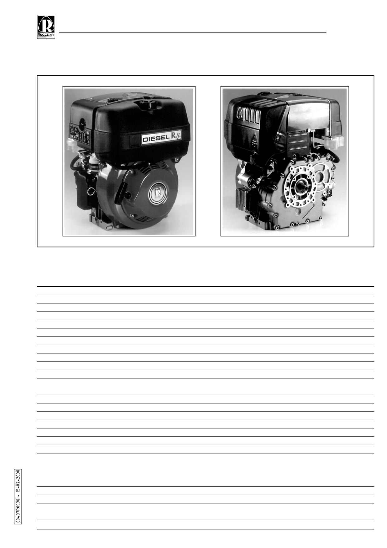
SERIES RY DIESEL ENGINES
1.
TECHNICAL SPECIFICATIONS
MODEL
Ry85.0
Ry85.1
Ry100
Ry101
Ry120
Ry121
Cycle
4-stroke Diesel
Injection
direct
Cooling
forced air with fan flywheel
Lubrication
forced with vane pump
Governor
centrifugal with weights
Number of cylinders
1
Swept volume
cc.
382
382
431
431
505
505
Bore
mm
80
80
85
85
87
87
Stroke
mm
76
76
76
76
85
85
Rpm
3000
3600
3000
3600
3000
3600
Compression ratio
19.5:1
19.5:1
18.5:1
18.5:1
18.5:1
18.5:1
PTO spinning
anti-clockwise
direction
Maximum torque
Nm(rpm)
19(2200)
19(2200)
22(2200)
22(2200)
27(2200)
27(2200)
Governor rpm error margin
5%
5%
5%
5%
5%
5%
Recommended battery
Ah(Amp)
60(300)
60(300)
60(300)
60(300)
60(300)
60(300)
Max. intake vacuum
KPa
4.5
5
5
5.5
5.5
6
Max. exhaust back pressure
KPa
6.5
7.3
7
7.8
7.5
8.4
Quantity of air for combustion
m³/h
31
37
35
42
41
49
Dry weight
Kg
45
45
46.5
46.5
48
48
PTO side
45°(35°)
45°(35°)
45°(35°)
45°(35°)
45°(35°)
45°(35°)
Maximum non-continua-
Pulley side
35°(30°)
35°(30°)
35°(30°)
35°(30°)
35°(30°)
35°(30°)
tive slant
Right side
40°(30°)
40°(30°)
40°(30°)
40°(30°)
40°(30°)
40°(30°)
(continuative)
Lato sinistro
45°(30°)
45°(30°)
45°(30°)
45°(30°)
45°(30°)
45°(30°)
Casing oil capacity
l.
1.3
Diesel fuel tank capacity
l.
5
Max axial load on drive
Kg
300
shaft (non continuative)
5.0
D IESEL
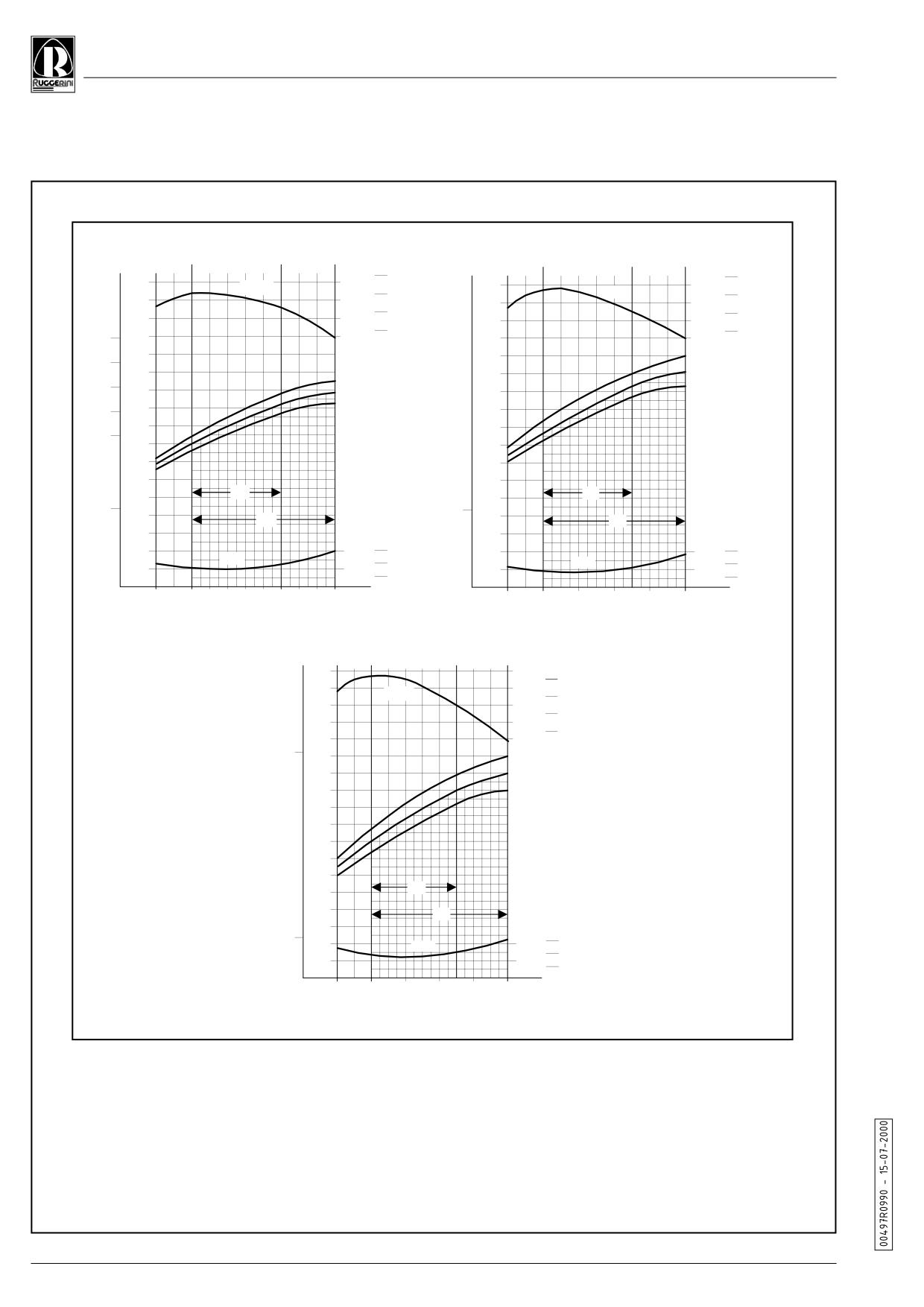
2. POWER GRAPHS
kW
CV
Kg m
N m
Kg m
N m
kW
CV-HP
20
23
2
2.3
Mt-N
Mt-N
19
22
1.9
2.2
18
21
1.8
2.1
17
20
8
1.7
8
2
10
10
7
7
N
9
9
NB
6
N
6
8
8
NA
NB
7
NA
7
5
5
6
6
4
4
5
5
3
4
3
4
3
3
2
2
2
U1
2
U
1
1
1
1
1
U2
U
2
g/CV-h
g/kW-h
g/CV-h
g/kW-h
205
280
205
280
C-N
260
C-N
260
185
185
240
240
g/min
1600
2000
2400
2800
3200
3600
rpm
g/min
rpm
1600
2000
2400
2800
3200
3600
RY85.0 - RY85.1
RY100 - RY101
Kg m
N m
kW
CV-HP
2.8
27
2.7
Mt-N
26
2.6
25
2.5
24
2.4
9
12
N
8
11
NB
10
7
NA
9
6
8
5
7
6
4
5
3
4
U
1
3
2
U
2
2
g/CV-h
g/kW-h
1
1
270
195
C-N
250
175
230
g/min
1600
2000
2400
2800
3200
3600
rpm
RY120 - RY121
N:
Power for automotive service (DIN 70020)
NB:
Non-overloadable power (DIN 6271)
NA:
Continuative overloadable power (DIN 6271)
U1:
Normal field of use, 3,000 rpm engine rate
U2:
Normal field of use, 3,600 rpm engine rate
Mt-N:
Torque rate corresponding to curve N
C-N:
Specific consumption with reference to curve N
With ambient temperatures exceeding 20°C (+68°F) or altitudes above sea level, the engine sustains a 2% power loss for every
5°C temperature increase and 1% for every 100 meters of increased altitude.
6.0
service
3.
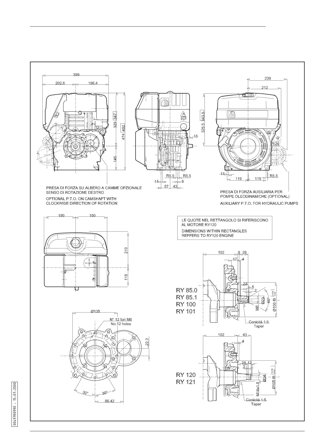
OVERALL DIMENSIONS
7.0
D IESEL
4.
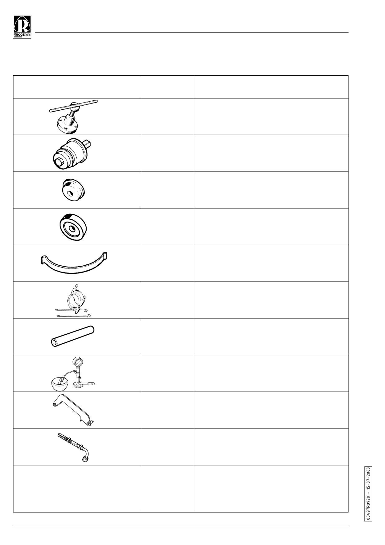
SPECIAL TOOLS
TOOL
CODE
DESCRIPTION
Flywheel puller
365.02
(also used for RD series engines)
Tool to mount and demount main bearings
365.90
(also used for MD series engines)
Plug to mount and demount main bearings
366.22
366.23
Sleeve to insert main bearings
365.77
Piston mounting tool
Crankshaft gear puller
365.10
(also used for series RD engines)
366.21
Punch to insert By-pass valve
365.43
Injector test bench
366.24
Tool to stagger injection lead
365.94
Capillary tube for injection lead
8.0
service
5.
MAINTENANCE SCHEDULE
OPERATION
8
50
100
200
500
2500
Air filter oil level (for engines with wet air filters)
Engine block oil level
Battery fluid level
Rocker arm valve play
Injector calibration
Air filter
Cylinder and head fins
Fuel tank
Internal oil filter
Injectors
Air filter oil (for engines with wet oil filters) [*]
Engine block oil [*]
Air filter cartridge
Fuel filter
Dry air filter
General overhaul
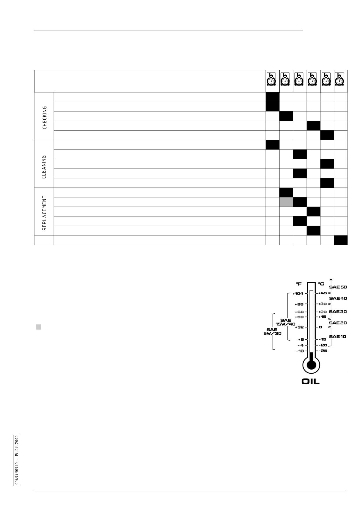
[*] Use oil for Diesel engines according to MIL-L-2104D specifications with detergent
degree S.3 (MIL-L-45199B) type AGIP SUPERDIESEL MULTIGRADE 15W/40.
use SAE 5W/30 oil if the engine operates in places where the temperature is below
( ) First oil change.
The maintenance operations refer to engines that operate in normal environmental
conditions (temperature, degree of humidity, degree of dust in the environment) and can
sensibly vary, depending on the type of use (the air filter oil must be changed every 4-5 hours
in dusty places).
Overhauls include : grinding the valve housings and guides, overhauling the injector and
injection pump, inspection of the injector protrusion, cylinder and piston replacement,
replacement of the main bearings.
9.0
D IESEL
6.
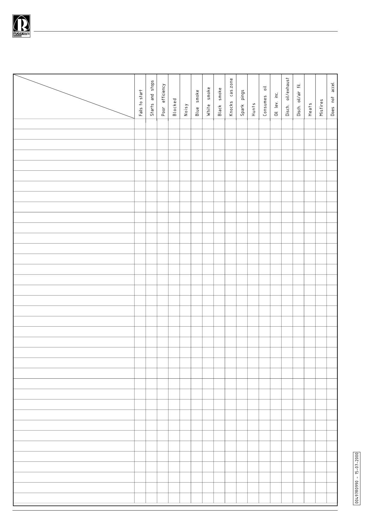
TROUBLESHOOTING TABLE
DEFECT
PROBABLE CAUSE
Air filter clogged
●
●
Con rod small end with excessive play
●
Engine running in
●
Unsuitable fuel
●
●
●
●
Air intaken by injection pump
●
●
●
●
Fuel filter clogged
●
●
Fuel tank empty
●
Worn main bearing
●
Clearance insufficient
●
●
Clearance excessive
●
●
●
●
Timing system gears defective
●
Head and cylinder fins clogged
●
Valve guides worn
●
●
Piston seized
●
●
●
●
Cylinder worn
●
●
●
Excessive rocker arm play
●
●
Regulator spring defective
●
Pipe clogged
●
●
Incorrect injection lead
●
●
●
●
●
Injection pump defective
●
●
Injection pump valve defective
●
●
Intake valve without play
●
Injector defective
●
●
●
●
●
Injector with clogged holes
●
●
Oil splash guard seals defective
●
Exhaust valve burnt out
●
●
Worn main or big-end bearing
●
Excessive load
●
●
Regulator lever with too much play
●
Tank plug hole blocked
●
Too much oil in casing
●
●
Hardened injection pump lever
●
●
Worn piston rings
●
●
●
Slack pump delivery union
●
●
●
Engine cold
●
Low idling rate
●
Change rate insufficient
●
10.0
service
7.
ENGINE IDENTIFICATION
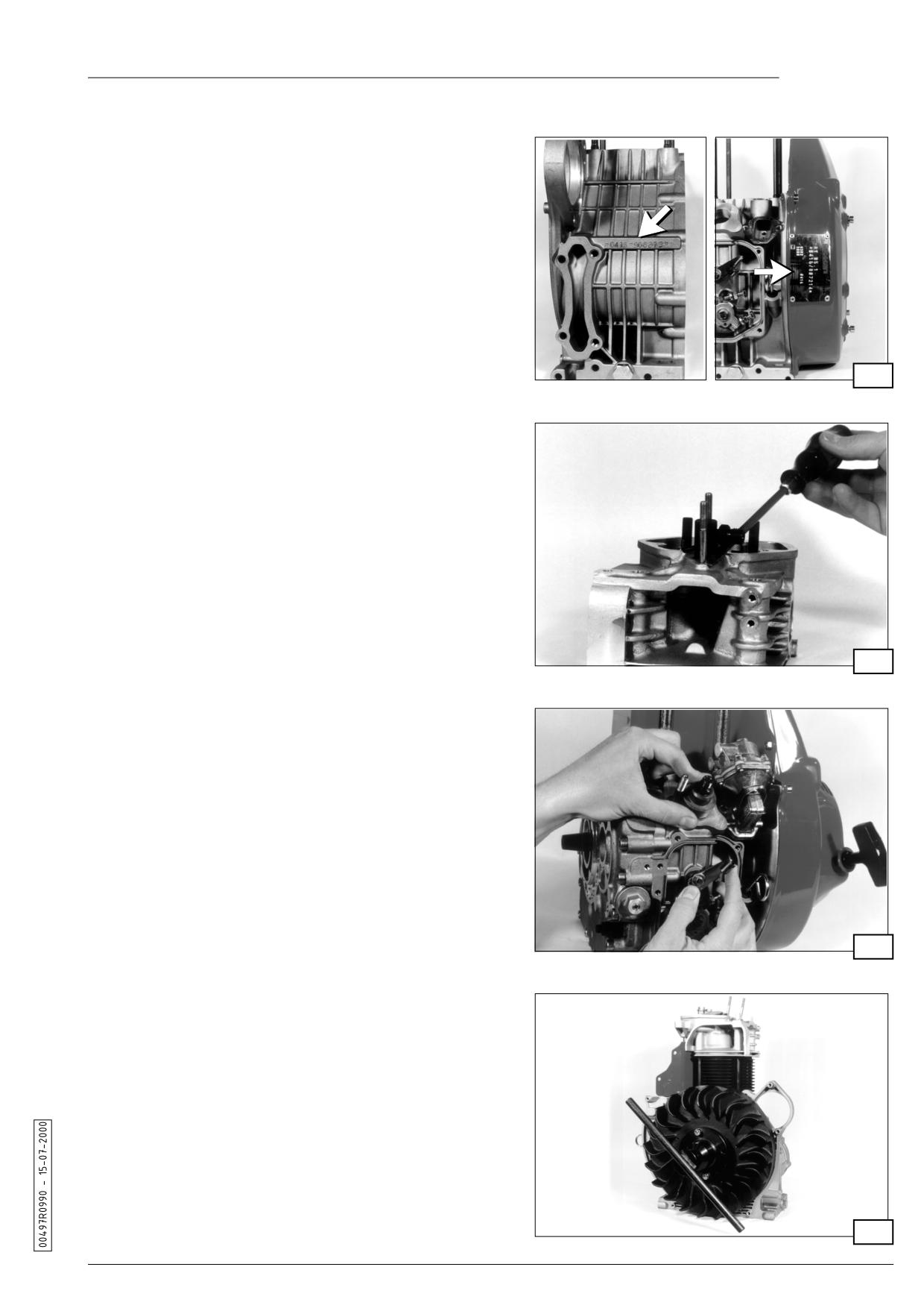
The type of engine and serial number are stamped on the
crankcase and on the data plate affixed to the conveyor (fig.
1).
Always indicate these engine identification numbers when
ordering spare parts or making requests under guarantee.
1
8.
DEMOUNTING THE ENGINE
8.1 Removing the injector
Slacken off the fuel delivery pipe, remove the fixing bracket
and take out the tube.
Remove the injector by levering it out with a screwdriver, as
indicated in fig. 2.
2
8.2 Removing the injection pump
Mark the position of the injection pump in relation to the engine
casing (if this has not already been done).
Remove the injection tube and take out the fuel pipes.
The pump can only be removed when the stop lever has been
turned to the stop position. To do this, the pump must be
pressed towards the housing as shown in fig. 3.
3
8.3 Removing the flywheel
Remove the fuel tank, the air conveyor and flywheel nut.
Remove the flywheel using puller code 365.02 as indicated in
fig. 4.
WARNING: do not strike the puller in an axial direction during
this operation.
4
11.0
D IESEL
8.4 Removing the cover on the timing system side
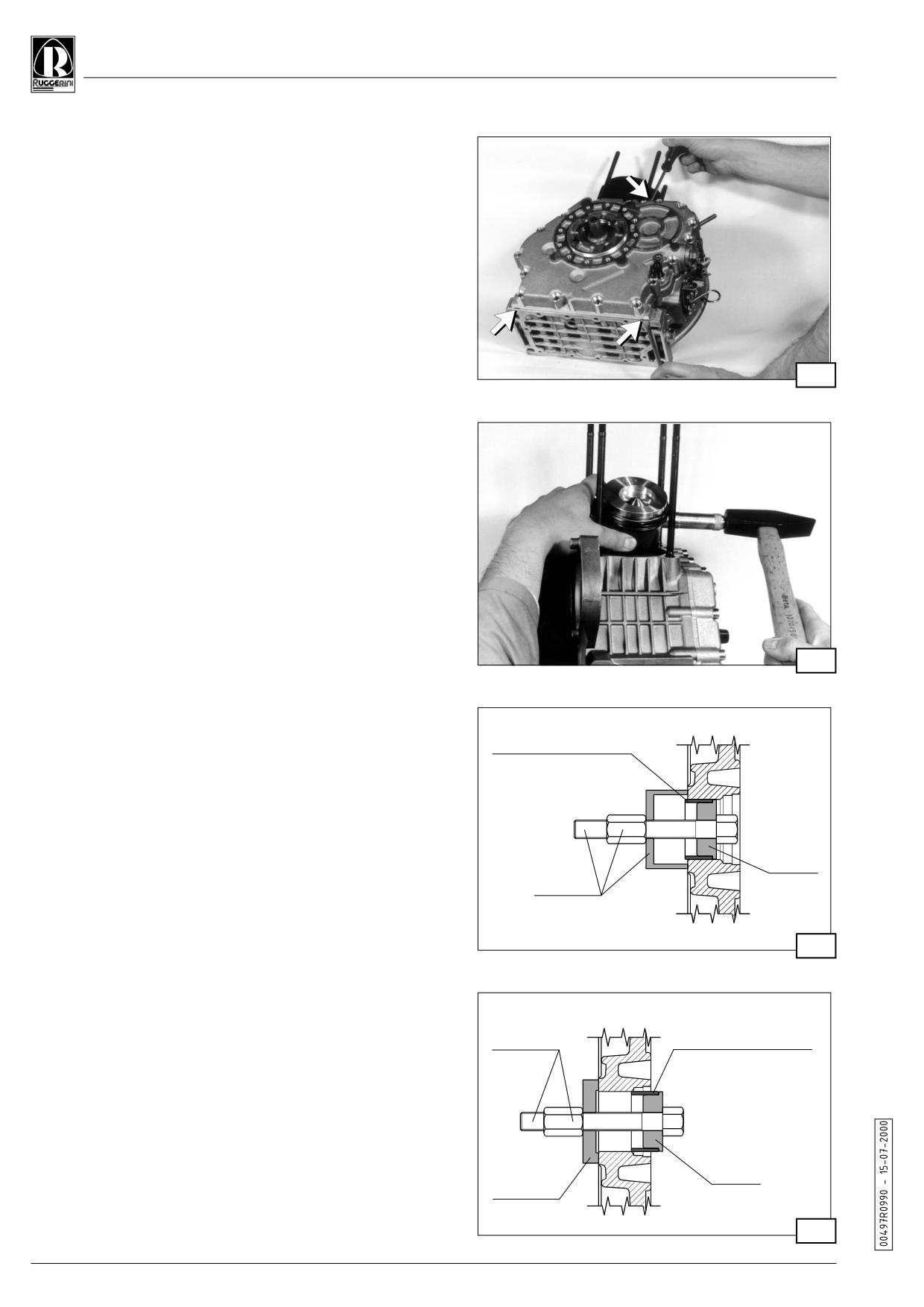
Slacken off the screws around the perimeter of the cover on
the timing system side. Split the cover from the engine casing
by levering with a screwdriver in the points indicated in fig. 5.
Warning: to prevent damage to the main bearings, it is
advisable to demount the cover from the timing system side
with the engine cold.
5
8.5 Demounting the piston
Take out the piston pin as shown in fig. 6.
Warning: do not demount the head when hot or the retention
surfaces could be damaged.
8.6 Demounting and remounting the main bearings
Use tool code 365.90 and plug code 366.22 (fig. 7) to
6
demount the main bearings from the engine casing and cover
on the timing system side.
To fit the main bearing back into the engine casing, use tool
code 365.90 with plug code 366.22 and sleeve code 366.23
side A (fig. 8).
Main bearing
To mount the main bearing on the cover on the timing system
side, use tool code 365.90 with plug code 366.22 and sleeve
code 366.23 side B (fig. 8).
During the assembly operations, make sure that the bearing
holes match the oil ducts by making reference marks with a
366.22
felt-tip pen.
365.90
Make sure that the reference mark on the bearing edge points
towards:
- the casing interior
7
- the outer part of the timing system cover.
WARNING
Proceed with the following inspections after assembly:
365.90
Main bearing
Cover on timing system side
The main bearing must project 1.7 to 2 mm in relation to the
bearing surface of the bull ring (inner side of cover).
Engine casing
The main bearing must be flush with the bearing surface of
the shimming ring (inner side of casing).
366.22
366.23
8
12.0
service
9.
INSPECTIONS AND OVERHAULS
9.1 Head
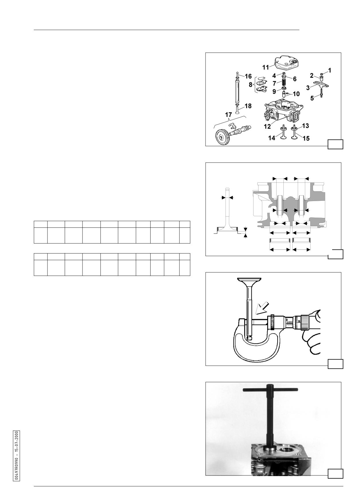
Parts indicated in fig. 9.
1. Nut - 2.Nut with ball - 3. Rocker arm - 4. Cotters - 5. Rocker arm
stud - 6. Upper cap - 7. Spring - 8. Air-relief valve - 9. Lower cap - 10.
Valve guide - 11. Rocker arm cover - 12. Head - 13. Valve housing
- 14. Exhaust valve - 15. Intake valve - 16. Rocker arm rod - 17.
Camshaft - 18. Tappets.
The head is made of aluminium with valve guides and housings
in faced cast iron.
Do not demount the head when hot to avoid deformations.
remove any carbon deposits from the head and check the
9
cylinder bearing surface. Level it off to a depth of no more than
0.3 mm if deformed.
The head must not be cracked or deformed. If such faults are
discovered, replace the part after consulting the spare parts
1 = intake
B
B
2 = exhaust
catalogue.
9.2 Valves - Guides - Housings
F 1
Clean the valves with a metal brush and replace them if the
F2
tops are deformed, cracked or worn.
A
A
RY85.0 - RY85.1
E
E
øA
øB
øC1
øC2
øD1
øD2
øE(*)
øF1
øF2
G
13
13.025
36.630
33.630
36.5
33.5
7
6.96
6.945
0.8
D 1
D2
to
to
to
to
to
to
to
to
to
to
13.01
13.037
36.645
33.645
36.525
33.525
7.01
6.97
6.955
1
G
C 1
C 2
RY100 - RY101 - RY120 - RY121
10
øA
øB
øC1
øC2
øD1
øD2
øE(*)
øF1
øF2
G
13
13.025
40.13
35.13
40
35
7
6.96
6.945
0.8
to
to
to
to
to
to
to
to
to
to
13.01
13.037
40.145
35.145
40.025
35.025
7.01
6.97
6.955
1
(*) with guide mounted.
measurements in mm
Check the dimensions of the valve stem (fig. 11) and the play
between the guide and valve. Ream the guide to the dimensions
indicated in the table. Change the guide and valve if the play
exceeds 0.1 mm.
The valve housings will always need to be ground when new
guides are mounted. Valve guides oversized on the outside by
0.10 mm are available.
After the engine has been used for a lengthy period of time,
valve knocking in their housings at high temperatures will
11
harden the housing tracks and make manual milling difficult to
carry out.
When this happens, remove the hardened surface layer with
a grinder at 45° (Fig. 12).
The valve retention track will widen when the valve housing is
machined. Final adaptation of the valve in the housing must be
carried out by smearing fine grain lapping compound in the
housing and turning the valve with a light pressure and with an
alternate movement until the surfaces bed perfectly (fig. 13).
Comply with the valve embedding values as indicated in the
table (G, fig. 10).
Warning: when the valve embedding values are lower than
those prescribed, the valves could interfere with the piston.
12
13.0
D IESEL
Grinding-in must always be carried out when new valves or
housings are mounted. Valve housings oversized on the
outside by 0.5 mm are available.
Thoroughly wash the valve and housing with petroleum or
gasoline to eliminate lapping paste residues or swarf.
Proceed in the following way to make sure that the valve and
seat are tight:
1) Mount the valve on the head with cap string and cotters
(see fig. 9)
2) Overturn the head and pour a few drops of diesel fuel or oil
on to the edge of the valve top
13
3) Blow compressed air into the head duct. Plug the edges of
the duct itself to prevent air escaping.
If there are air leaks in the form of bubbles between the
housing and valve, demount the valve and grind-in again.
14.91
±5%
24.72
9.3 Valve springs
K g
±5%
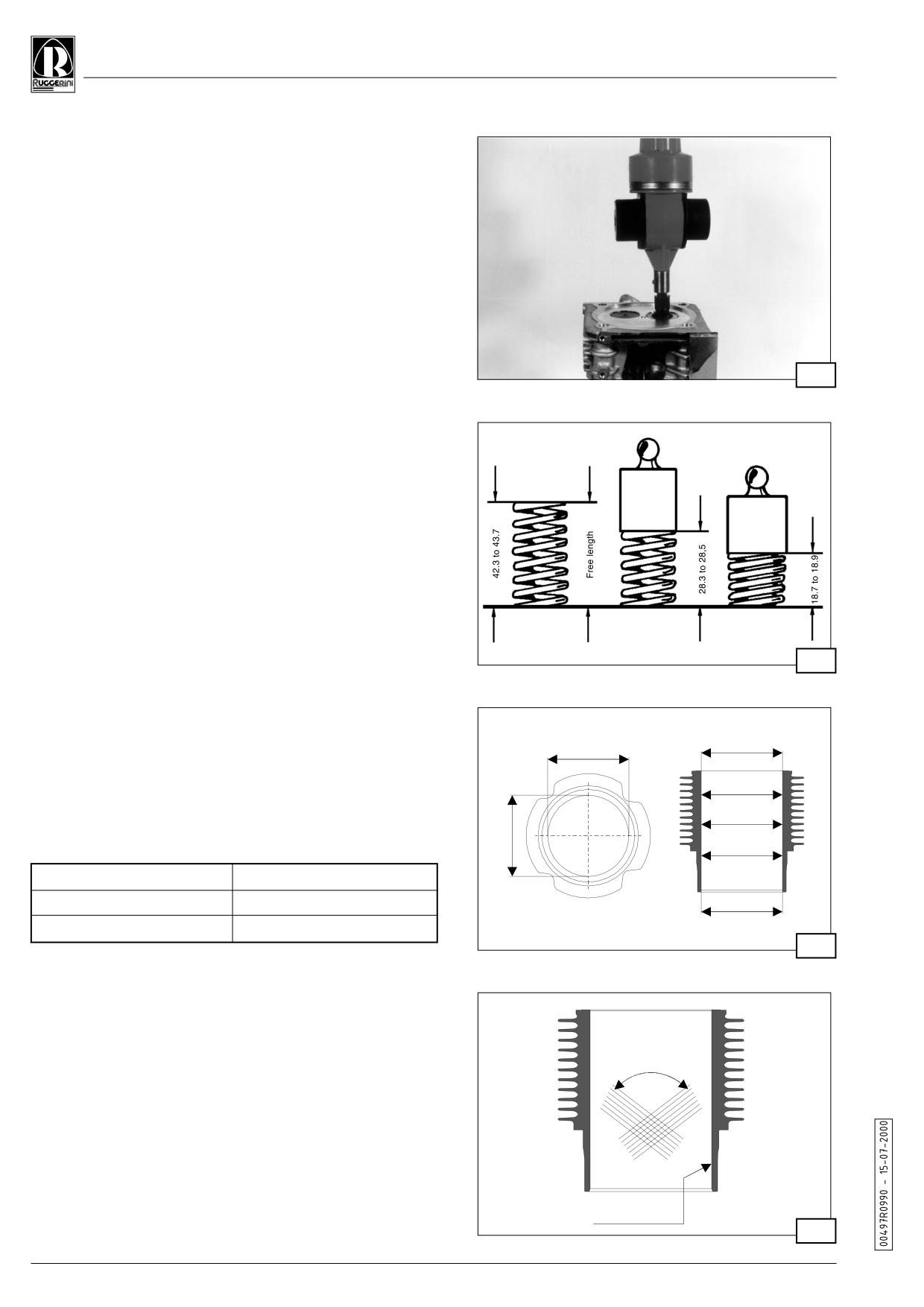
Check the length of the spring as indicated in fig. 14 to identify
K g
any yielding.
Replace the springs if the values are different.
9.4 Rocker arms
14
Make sure that there are no evident signs of wear on the
contacting surfaces. Replace the parts if necessary.
9.5 Cylinder
In special cast iron with integral liner. Use a bore gauge to
check the two internal diameters (C-D) perpendicular to each
other and at different heights (fig. 15). Maximum tolerated
taper error (A-B) and ovality error (C-D): 0.06 mm.
Cylinder diameter:
RY85.0 - RY85.1
Ø 80 to 80.020
RY100 - RY101
Ø 85 to 85.020
RY120 - RY121
Ø 87 to 87.020
15
Just replace the piston rings if the cylinder diameter does not
exceed the values above or if the cylinder is slightly scored on
the surface. In this case, to ensure that the piston rings and
cylinder adapt to each other as soon as possible, restore liner
roughness by passing 80 to 100 grain emery cloth soaked in
diesel fuel and wound around the palm of the hand over its
inner surface (fig. 16) until this appears cross-hatched. Follow
these operations by thorough washing in gasoline or petroleum.
Replace the cylinder and piston if there is a ridge in zone "X"
fig. 16 of the cylinder and if tapering and ovality exceed the
previously given values.
16
14.0
service
9.6 Piston rings - Piston - Pin
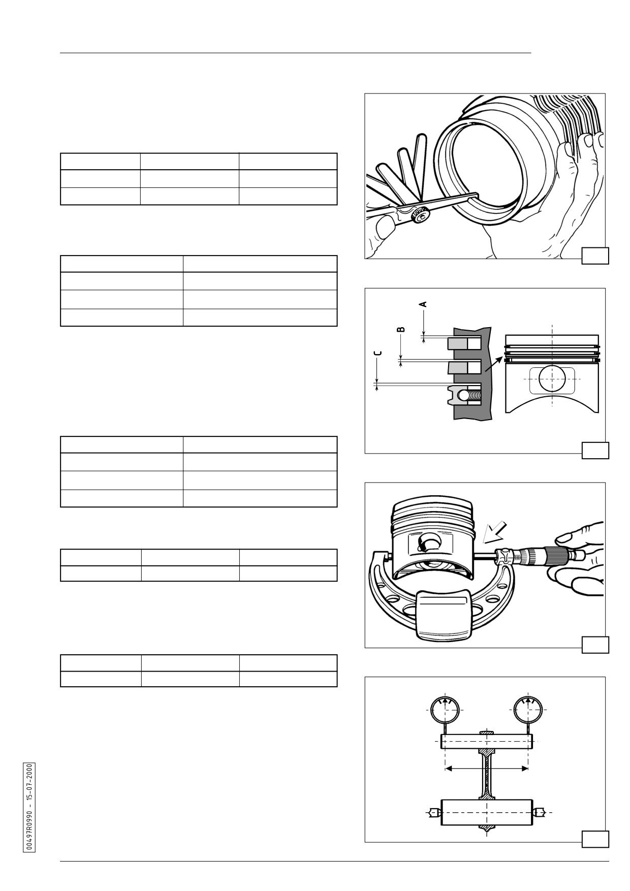
To gauge the wear on the piston rings, put them into the
cylinder from the bottom side and measure the distance
between the free ends (fig. 17), which must be:
Piston ring
Assembly mm
Wear limit mm
Compression
0.30 to 0.50
0.80
Oil scraper
0.25 to 0.50
0.80
Make sure that the piston rings slide smoothly in the slots and
use a thickness gauge to check the play between the slot and
ring (fig. 18). Replace the piston and rings if the play exceeds:
17
Piston ring
Limite di usura mm
1st Compression
A = 0.22
2nd Compression
B = 0.19
3rd Oil scraper
C = 0.16
WARNING: it is advisable to replace the piston rings whenever
the piston is demounted.
Checking the piston diameter:
the diameter of the piston must be measured at a distance
from the base (fig. 19) of approximately:
10 mm (for RY85.0 - RY85.1 - RY100 - RY101 series engines
11 mm (for RY120 - RY121) series engines
Engine
Diameter mm
18
RY85.0 - RY85.1
79.915 to 79.935
RY100 - RY101
84.915 to 84.935
RY120 - RY121
86.915 to 86.935
Check the play between cylinder and piston. Replace the
parts if play exceeds 0.150 mm.
Play between pin and piston mm:
Pin Ø mm
Play mm
Wear limit mm
21.997 to 22.002
0.003 to 0.013
0.040
9.7 Connecting rod
Coupling between the small end hole of the connecting rod
and pin is made without a bearing.
Play between connecting rod small end and pin mm:
19
Pin Ø mm
Play mm
Wear limit mm
21.997 to 22.002
0.023 to 0.038
0.070
0
0
+
- 0.02
+
- 0.02
Check connecting rod axes parallelism in the following
0.02+
0.02
+
-
+
-
way:
1) Insert the pin into the small end hole of the connecting rod
and a calibrated plug into the big end (with the bearing
mounted).
100
m m
2) Rest the plug on two prisms arranged on a surface plate or
between two centers (fig. 20).
3) Use a centesimal comparator to check that the difference
between the readings made at the ends of the pin does not
exceed 0.02 mm. square up the connecting rod if the
20
deformation is greater (max. 0.05 mm).
15.0
D IESEL
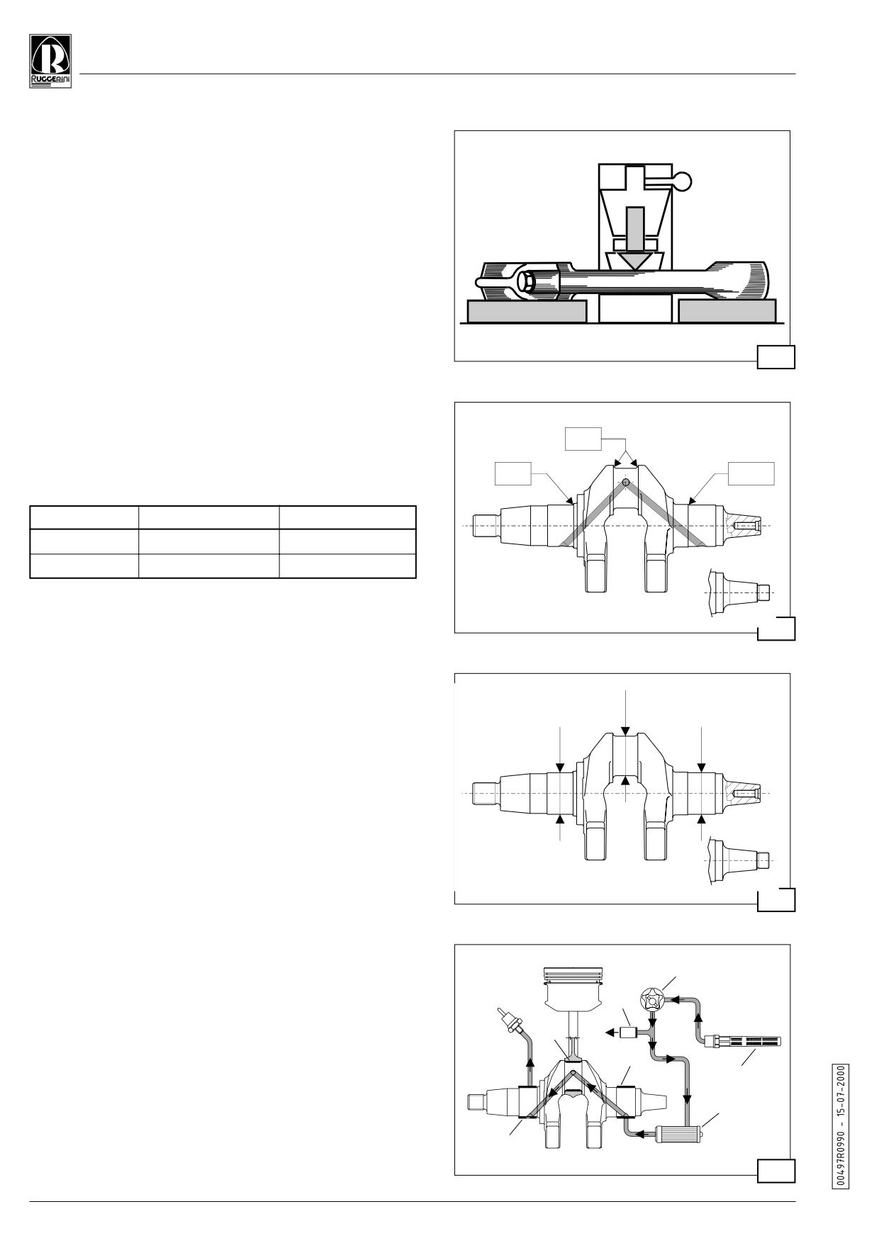
The operation is carried out by applying a calibrated pressure
to the convex side in the middle of the connecting rod stem set
on surface plates (fig. 21).
9.8 Crankshaft
It is advisable to check the condition of the crankshaft whenever
the engine is demounted and particularly when cylinders and
pistons must be replaced following wear due to dust having
been intaken.
Thoroughly clean inside the oil ducts using a shaped metal
point.
If there are heavily caked incrustations, immerse the crankshaft
into a bath of petroleum or gasoline before proceeding with the
21
scraping operation (fig. 22).
When the crankshaft is perfectly clean, check with a micrometer
to ascertain wear and main journal ovality in the two
perpendicular positions (fig. 23).
R 3
Grind the shaft if the wear exceeds the values in the table by
R
1
R
0.5
0.08 mm or more.
Dimension
STD mm
-0,25 mm
A C
41.97 to 41.99
41.72 to 41.74
B
39.98 to 40
39.73 to 39.75
NOTE: crankshaft grinding operations of more than 0.25
mm should not be carried out.
2
Undersized bearings can be mounted without any reaming
work required.
WARNING: do not remove material from the main journal
shims during the grinding operation as this would alter
crankshaft float. Also make sure that the grinder radii
correspond to those indicated in fig. 22 to prevent fracture
sections from initiating on the shaft.
9.9 Oil retention rings
Make sure that the rings have not hardened in the retention lip
and that there is no sign of breakage or wear.
9.10 Lubrication circuit
23
Lubrication of the main bearings and connecting rod big end
is the forced type with a rotor oil pump.
Excessive pressure in the oil circuit is prevented by the by-
pass valve (3, fig. 24).
2
All the other parts are splash lubricated.
Oil vapours are eliminated from inside the casing by a
3
diaphragm mounted in the rocker arm cover.
7
6
Illustration in fig. 24:
1
1. Internal intake oil filter in casing - 2. Oil pump - 3. By-pass valve
- 4. Engine oil filter - 5. Pressure switch - 6. Main bearing - 7. Big end
4
bearing.
6
24
16.0
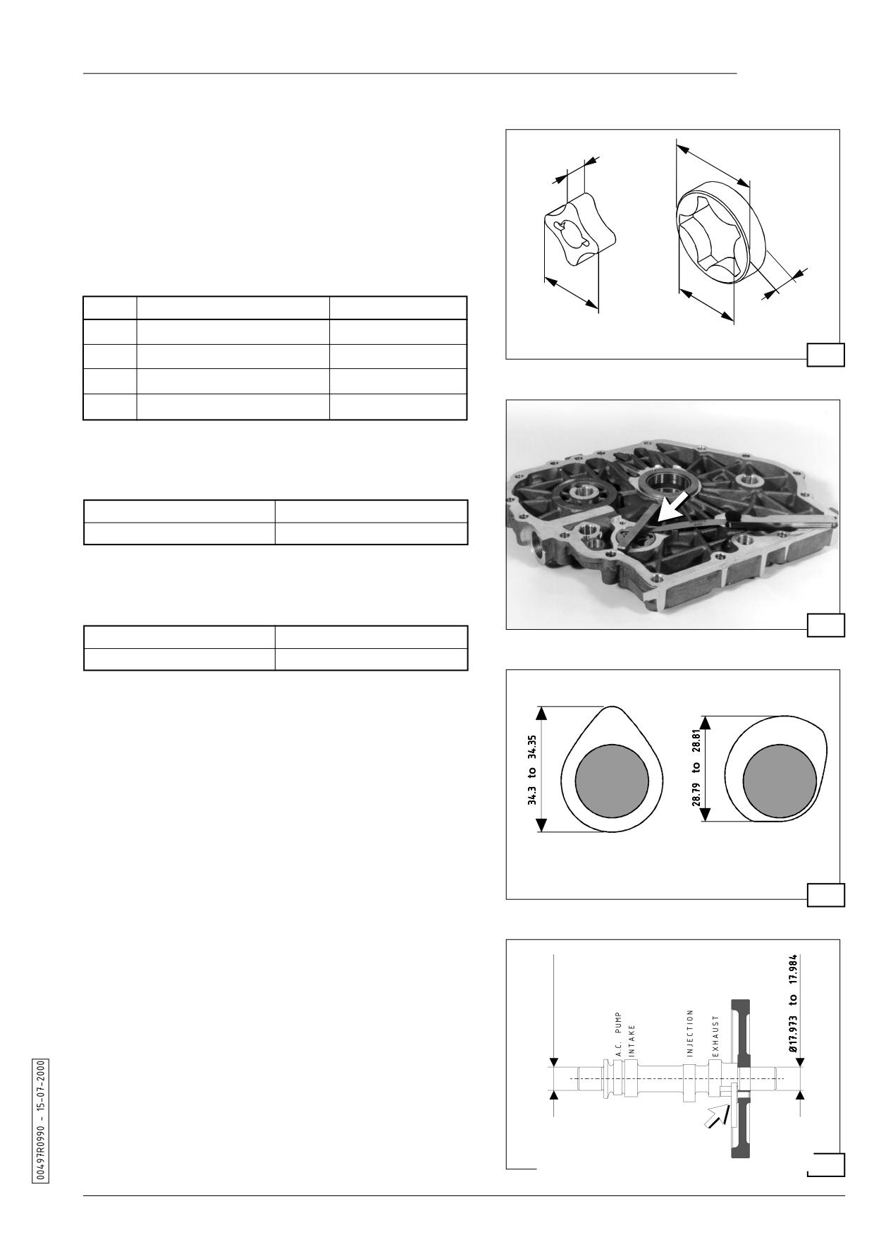
service
9.11 Checking the oil pump
Make sure that the oil pump cover is in a good condition.
D
F
After demounting, examine the rotors and replace them if their
lobes or centerings are damaged. To check the degree of
pump wear, measure the dimensions of rotor A and rotor B
(fig. 25) and compare them with the values in the following
table:
OIL PUMP ROTOR DIMENSIONS AND PLAY
C
E
F
Assembly mm
Limite usura mm
C
Ø25.97 to 25.99
Ø25,92
Rotor A
Rotor B
D
Ø34.96 to 34.99
Ø34,87
25
E
26.205 to 26.27
26,31
F
7.97 to 7.99
7.93
The entire pump must be replaced if the wear is greater.
The coupling play between the external oil pump rotor and the
housing on the cover of the timing system is:
Assembly mm
Limite di usura mm
0.16 to 0.215
0.345
Make sure that the oil pump recess in relation to the surface
of the timing system cover (fig. 26) is between :
26
Assembly mm
Wear limit mm
0.03 to 0.07
0.11
Make sure that there are no impurities in the by-pass valve on
the cover on the timing system side by unscrewing the
inspection plug near the fuel flow limiter.
9.12 Camshaft
Make sure that the cams and bearing pins are not scored or
worn. Check the dimensions as indicated in fig. 27.
Intake
I njection
Check the dimensions of the camshaft pins (D, fig. 28) and the
Exhaust
corresponding housings in the casing and cover on the timing
27
system side. The max. xonstructional play is 0.032 to 0.061
mm.
WARNING: replace the shaft if the wear on the cams or pins
exceeds:
0.1 mm (injection cams and pins)
0.3 mm (intake and exhaust cams)
NOTE: make sure that the valve lifting mechanism (fig. 28, A)
is not damaged and that there is nothing to hinder its movement.
28
17.0
D IESEL
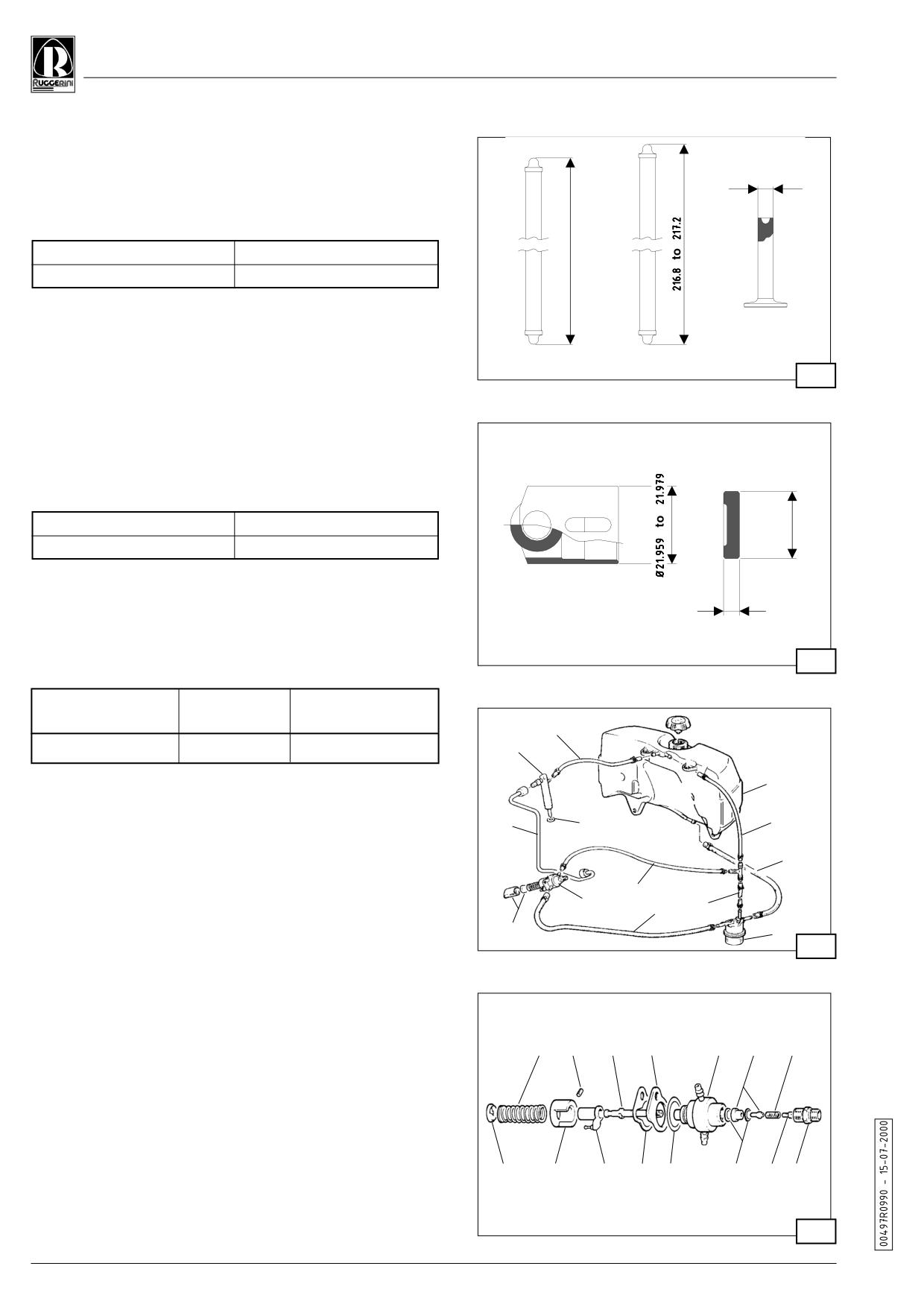
9.13 Tapets and rocker arms
Make sure that there is no wear, scoring or signs of seizure on
95
the surfaces of the tappets (fig. 29). Replace the parts if
necessary.
Tapet and housing coupling play:
Assembly mm
Limite di usura mm
0.005 to 0.029
0.10
The rods must be straight with ball shaped surfaces at the
ends and in good conditions (fig. 29).
RY85.0 -RY85.1
RY120
- RY121
RY100
- RY101
29
9.14 Injection pump tappets and pads
Replace the parts if the wear on their surfaces exceeds 0.1
mm (fig. 30).
Coupling play between the tappet and relative housing in the
crankcase:
Assembly mm
Wear limit mm
0.021 to 0.059
0.10
9.15 Fuel pump (optional)
Check the projection of the A.C. pump rod in relation to the
engine casing surface with the canshaft eccentric in the non-
operative position.
30
Rod length
Wear limit
Rod projection
mm
mm
mm
1
1
53.0 to 53.2
0.3
1.45 to 2.05
9
1
WARNING: the rod projection cannot be adjusted.
8
10
7
2
10. INJECTION COMPONENTS
7
5
7
4
10.1 Fuel circuit
Fuel supply is the gravitational type. An AC pump can be
6
3
mounted on request. Air bleeding is automatic.
31
Illustration in fig. 31:
1. Fuel tank - 2. Fuel pipe - 3. Fuel filter - 4. Fuel pipe - 5. Injection
pump - 6. Injection pump tappet - 7. Bleed tubes - 8. Injection
pipe - 9. Injector - 10. Washer - 11. Fuel return pipe.
14
12
10
8
6
4
3
10.2 Injection pump
Illustration in fig. 32:
1. Delivery union - 2. Filler - 3. Valve spring - 4. Delivery valve - 5.
Washers - 6. Monobloc pump casing - 7. Adjuster seal - 8. Flange
15
13
1
1
9
7
5
2
1
- 9. Pump seal - 10. Plunger - 11. Adjuster sleeve - 12. Plug - 13.
Adjuster block - 14. Spring - 15. Lower cap
32
18.0
service
10.3 Checking the injection pump
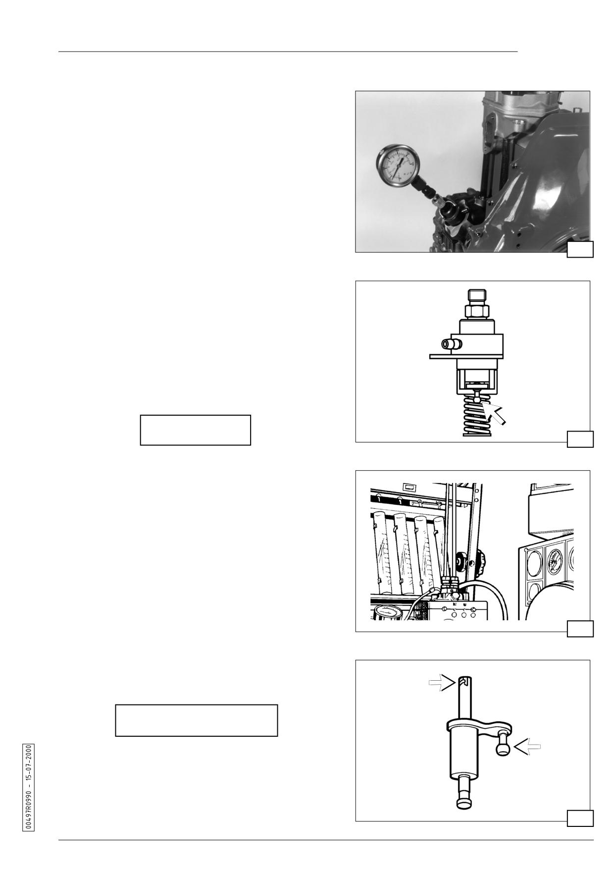
before demounting the injection pump, make sure that the
plunger unit, enbloc pump casing and valve are pressure tight
by proceeding in the following way:
1) Connect a pressure gauge with scale up to 600 Kg/cm² to
the fuel delivery pipe (fig. 33).
2) Set the regulating sleeve (fig. 34) to the average delivery
position.
3) Slowly turn the flywheel to make the plunger make one
compression stroke.
4) Read the indication on the pressure gauge. If it is lower
than 300 Kg/cm², the complete pump must be changed.
33
During the test, the pressure gauge needle will show a
progressive pressure increase until reaching a maximum
value, after which it will drop sharply back and stop at a lower
pressure value. Replace the valve if the pressure drop is more
that 50 Kg/cm² and continues to slowly drop lower.
The pressure must drop from 200 Kg/cm² to 150 Kg/cm² in
not less than 7 sec.
10.4 Injection pump calibration (fig.
35)
When the adjuster sleeve is 10.5 mm from the stop position
and the pump spins at 1,500 rpm, the amount of fuel for 1,000
deliveries must be between:
23 to 25 cc
34
Replace the pump if the values differ.
WARNING:
Check to make sure that plunger travel with the injection cams
in the non-operative position (BDC) at the start of delivery is:
1.9 to 2.0 mm
10.5 Injection pump assembly (fig. 37)
If the injection pump must be demounted, use an electric pen
to mark the adjuster block (M) with the enbloc pump casing (A)
and loosen the plug (N) after having heated it to make the
Loctite easier to release.
Comply with the following instructions when remounting the
35
parts:
1) Fit the washer (B), the delivery valve (C), the washer (D),
the valve spring (E), the filler (F) into the enbloc pump
casing (A) and torque the delivery union (G) to a value of:
A
4.3 to 5.4 Kgm (42.5 to 52.5 Nm)
2) Insert the adjuster seal (H).
B
3) Insert the flange (I).
4) Insert the plunger with helical profile (A, fig. 36) into the iner
housing of the adjuster sleeve from the side opposite the
sleeve pin (B, fig. 36).
36
19.0
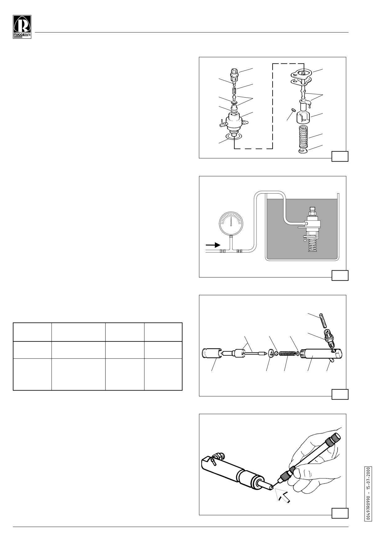
D IESEL
5) Insert the adjuster sleeve unit and plunger (L) into the
pump casing (A), making sure that the helical profile is
G
I
directed on a level with the return union with ball.
F
6) Fit in the adjuster block (M), matching the reference marks
E
applied during the demounting phase.
L
7) Tighten the plug (N) to a 0.5 to 0.6 Nm torque, locking it in
D
C
place with Loctite 290.
B
8) Insert the spring (O) and lower cap (P).
A
M
9) Compress the tappets in the various operating positions to
N
check that the adjuster sleeve (L) slides perfectly.
O
Resistance or jamming will make the engine to hunt during
operation.
H
P
37
10.6 Leak test
Plug the fuel return union and let air in through the fuelling
union at a pressure of 6 Kg/cm². Fully immerse the pump in
a receptacle containing diesel fuel for about 50 - 60 seconds
(fig. 38) and make sure that no bubbles appear when the
6 Kg/cm
tappet is compressed 53.6 mm, corresponding to the bottom
dead center point during work.
NOTE: the position of the pump adjuster sleeve is of no
importance for this test.
air
10.7 Injector
Details of fig. 39:
1. Filter - 2. Fuel inlet union - 3. Fuel return union - 4. Nozzle holder
- 5. Calibration washer - 6. Spring - 7. Pressure rod - 8. Spacer - 9.
Nozzle - 9. Ring nut.
38
10.8 Injector inspection and calibration
1) Clean the nozzle holes with a thin steel wire (fig. 40) with
the following diameters:
1
Engine
Diameter of steel
Number of
Diameter of
9
7
5
2
series
wire (mm)
holes
holes (mm)
RY85.0
0.21
4
0.22
RY85.1
RY100
RY101
0.24
5
0.25
RY120
10
8
6
4
3
RY121
39
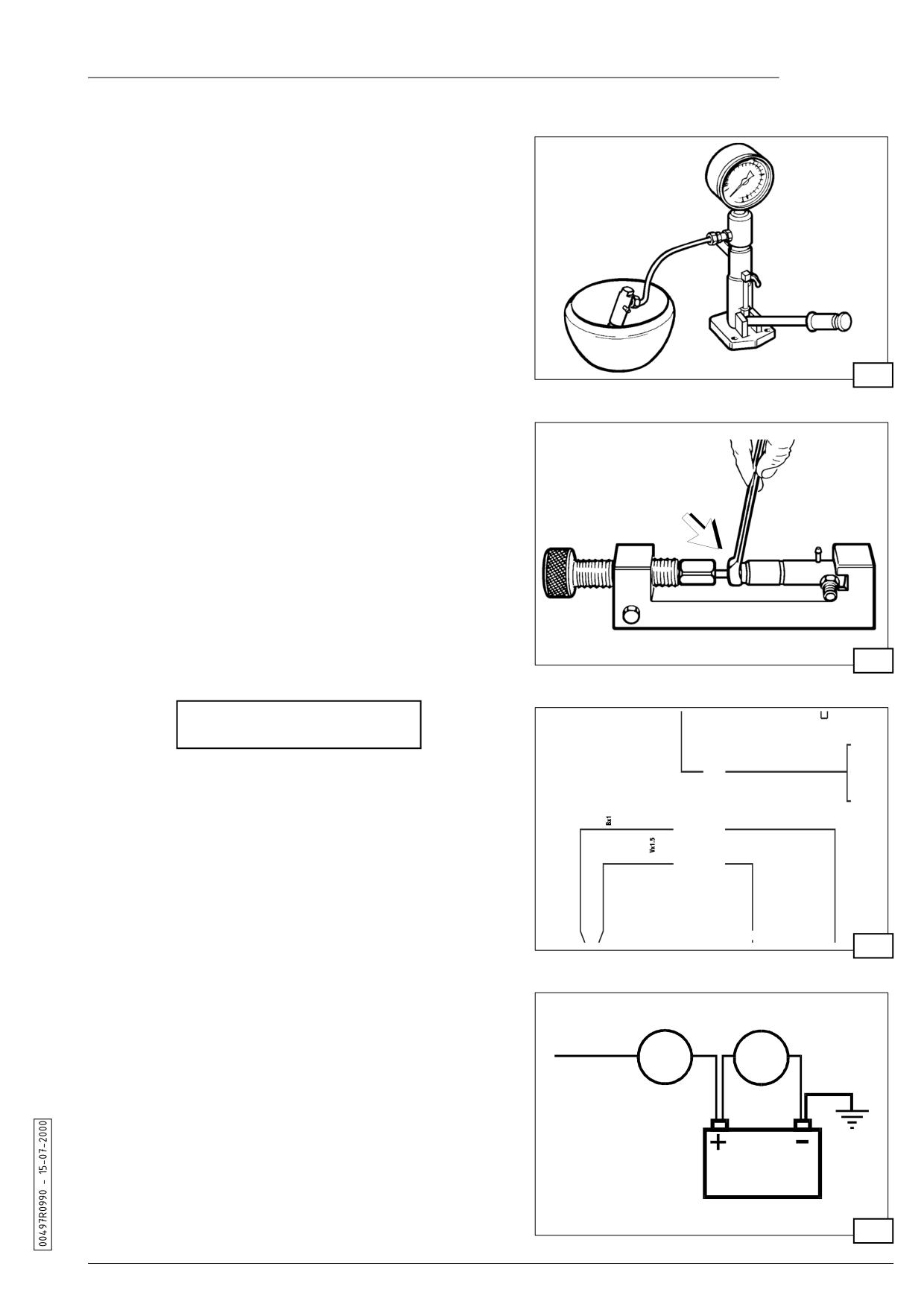
2) Mount the injector on the test bench (code 365.43, fig. 41).
Disconnect the pressure gauge and rapidly operate the
lever. The nozzle must make the characteristic "trilling"
sound and inject with a good atomizing action.
3) Connect the pressure gauge. Slowly depress the level in a
continuous way until injection occurs.
The injector needle must "open" at the pressure of 230 to
238 bar. Vary the washer shims (N° 5 fig. 39) to calibrate
in the correct way.
4) Leak test: operate the test bench lever until the gauge
pointer is 20 Kg/cm² below the injection pressure value.
Nozzle tightness is good if no fuel comes out within 10 sec.
5) Checking for leaks on the nozzle return phase: operate
the test bench lever until the gauge pointer is 20 Kg/cm²
40
20.0
service
below the injection pressure value. Release the lever and
check the time it takes to drop. The pressure must drop to 150
to 100 Kg/cm² withinn 6 to 40 seconds.
- replace the nozzle if it drops in less than 6 seconds.
- if it takes longer than 40 seconds to drop, make sure that
there are no carbon deposits in the nozzle and that the
return holes are not clogged.
10.9 Demounting and remounting
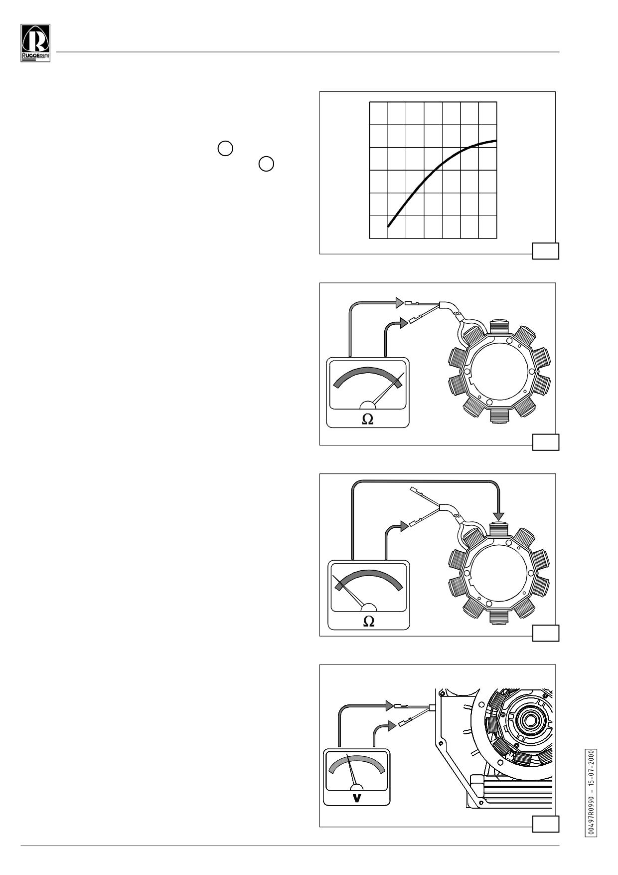
Loosen the ring nut that fixes the nozzle using a torque wrench
and as device like the one shown in fig. 42 which relieves the
41
pressure exercised by the spring on the ring nut.
1) Visual inspection: make sure that the needle housing is
not deformed or excessively rough.
The nozzle body must not show signs of wear or damage.
The holes must be free from carbon residues.
2) Smoothness test: the nozzle needle, which will have
been previously immersed in impurity-free fuel, should be
inserted into the body of the nozzle. Noz extract it by up to
a third of the guide length, holding the nozzle in a vertical
position. The needle must drop back into its housing
thanks to its actual weight alone.
Remount the injection in compliance with the order indicated
in fig. 39. Make sure that the plugs and centering pins on the
spacer (N° 8 fig. 39) match the relative holes in the housings.
Tighten the ring nut that fixes the nozzle to a value of:
42
Nx
33
Nx33
4.6 to 5.6 Kgm (45 to 55 Nm)
4
30
Mx1
Mx1
50
Rx2.5
3
11. ELECTRICAL EQUIPMENT
Rx1
8
15/54
11.1 Characteristics of the system
7
30
30/1
15
50
Starter motor: lh rotation direction (pinion side), 12V voltage
Nx2.5
rating, power 1.1 kW.
6
Internal alternator: 12V - 280W
Mx11
Gx1
Mx1.5
Gx1
Voltage regulator: electronic, with controlled diodes and
L.E.
2
5
indicator connection for battery recharger
Recommended battery: 12V 60Ah (300A).
Rx2.5
Optional accessories: control strip with remote control switch
43
and OIL ALARM plant.
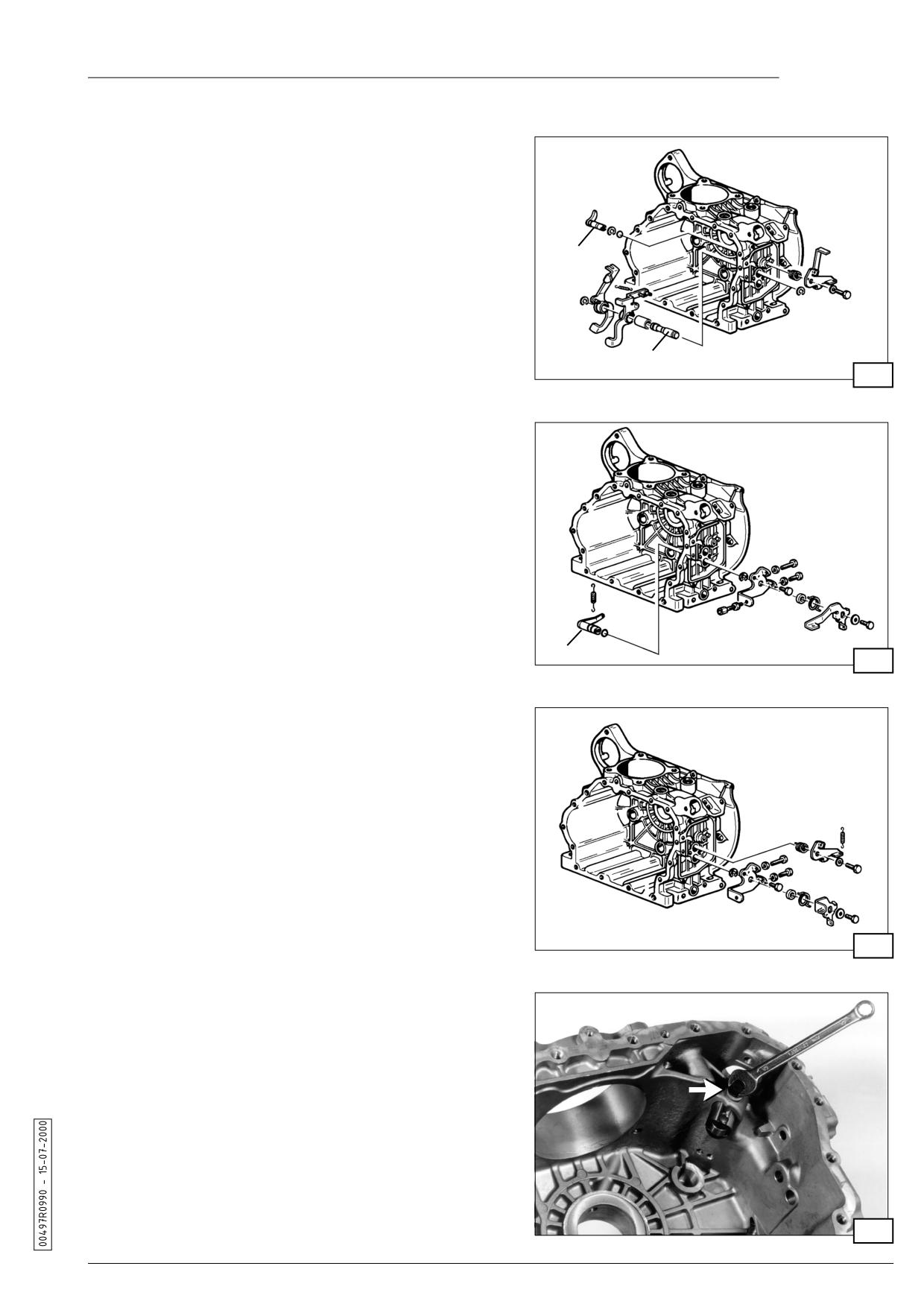
Illustration in fig. 43:
1. Ignition key - 2. Voltage regulator - 3. Starter motor - 4.
Battery - 5. Alternator - 6. Pressure switch - 7. Low battery
charge indicator - 8. Low oil pressure indicator.
A
V
CABLES: Colour x Section mm2
CABLE COLOURS: B= white
M= brown
N= black
R= red
V= green
44
21.0
D IESEL
11.2 Checking the system
A
1) make sure that the connections between the regulator and
alternator are correct and in good conditions
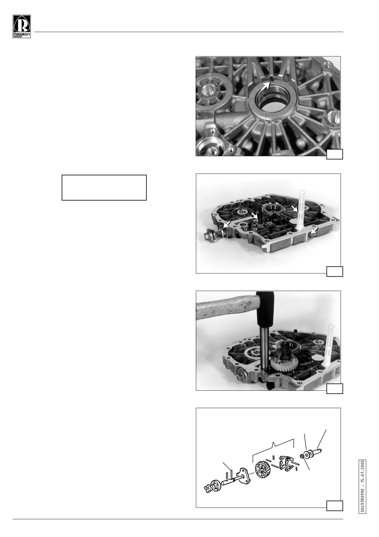
25
2) detach the wire from the remote control switch from the
terminal and fit on a d.c. amperometer (
A
,fig. 44)
20
3) coconnect a d.c. voltmeter to the battery terminals (
, fig.
V
15
44)
4) make a few no-load starts or introduce a 80−100W lamp
10
load at the battery lugs to keep the battery voltage below
13V.
5
5) accelerate the engine to a 3000 rpm rate. The current
indicated on the amperometer must correspond to the
1000
2000
3000
RPM
values in fig. 45.
45
6) disconnect the load (if any) and keep the engine at the
above mentioned rate for a few minutes. The battery
voltage must progressively increase until reaching about
14.2 V. Meanwhile, the charge voltage must drop to a
minimum value of about 2A, with a speed determined by
the battery charge condition.
7) if charge current is missing or is less than the given values,
check the alternator and replace the voltage regulator if
necessary.
11.3 Checking the alternator
With the engine at a standstill, disconnect the alternator wires
from the regulator and check:
1) using an ohmmeter, that the windings (fig. 46), null
46
resistance) and the insulation between wires and ground
(fig.47, infinite resistance) are unbroken. Replace the
stator if interruptions are discovered;
2) with a voltmeter, the voltage between the two yellow wires
(fig. 48). Accelerate the engine to 3000 rpm. The voltage
must be 33V.
If the values are more than 10V less than this, it means that
the rotor is demagnetized and that the alternator must be
replaced.
Warning:
1) the alternator does not deliver current when the yellow
cables are isolated
2) the alternator burns out if the yellow wires are grounded
3) the regulator may be damaged if the ground connection or
47
electrical connections are made in a slapdash way.
4) the alternator and regulator will immediately burn out if the
battery connections are inverted.
11.4 Ring gear
Make sure that the teeth of the crown wheel are not worn or
damaged. Heat the starting ring gear to a temperature of 200-
250 °C before fitting it on to the flywheel .
48
22.0
service
12. ENGINE ASSEMBLY
Important:
The instructions refer to engines updated at the time of
publication. Check the technical circulars for any
B
modifications.
Thoroughly clean the parts before remounting them.
Lubricate the moving parts to prevent seizures when the
engine is first started.
Replace the seals whenever the parts are remounted.
Use torque wrenches to tighten to the correct values.
A
49
12.1 Preparing the engine block
remove all traces of sealant or impurities from the bearing
surfaces with a copper plate or lapping stone, then proceed in
the following way:
1) Fit on the oil drain plugs without tightening them too much
(max. 2 Kgm) to prevent damage to the threads.
2) Mount the main bearing as indicated in section 8.6 on page
12.
3) Fit the benzing ring on to the pin of the regulator levers (fig.
49-A); apply Loctite 648 to the zone where the pin touches
the engine casing.
Insert the stop lever (fig. 49-B), the accelerator lever (fig.
50-C) and complete the assembly operations in compliance
C
50
with the sequencies indicated in figures 49 and 50.
4) Comply with the sequence indicated in fig. 51 for the
"motorstop" version.
51
12.2 Injection pump tappets
Insert the tappet into the injection pump housing in the engine
casing.
Fit the screw into the guide as shown in fig. 52
52
23.0
D IESEL
12.3 Timing system cover pre-assembly
Prepare the cover of the timing system in the following way:
1) Mount the main bearing as indicated in section 8.6 on page
12.
2) Fit in the pin and drive shaft bearing ring (fig 53).
3) Mount the oil pump rotors as described in section 9.11 on
page 17. Insert the plug and driving pin as shown in fig. 54-
A. Fix the oil pump cover in place by tightening the screws
to the following torque value:
53
0.8 to 1.0 Kgm
(7.8 to 9.8 Nm)
C
A
4) Insert the by-pass valve using tool code 366.21 (fig. 55);
D
mount the by-pass check screw with Loctite 648; mount
B
the by-pass valve inspection plug on the outside of the
cover on the timing system side.
5) Fit the retainer cap on the oil intake duct at the base of the
cover on the timing system side, using Loctite 648 (fig. 54-
B).
54
6) Tighten the internal oil filter (fig. 54-C).
7) Fit on the engine oil filter and relative plug including the O-
Ring (fig 54-D).
8) Mount the rpm governor, in compliance with the alphabetical
sequence given in fig. 56.
9) Fit in the fuel flow limiter
10) Mount the oil retention ring as indicated on page 27 fig.67.
55
D
C
B
A
E
56
24.0
service
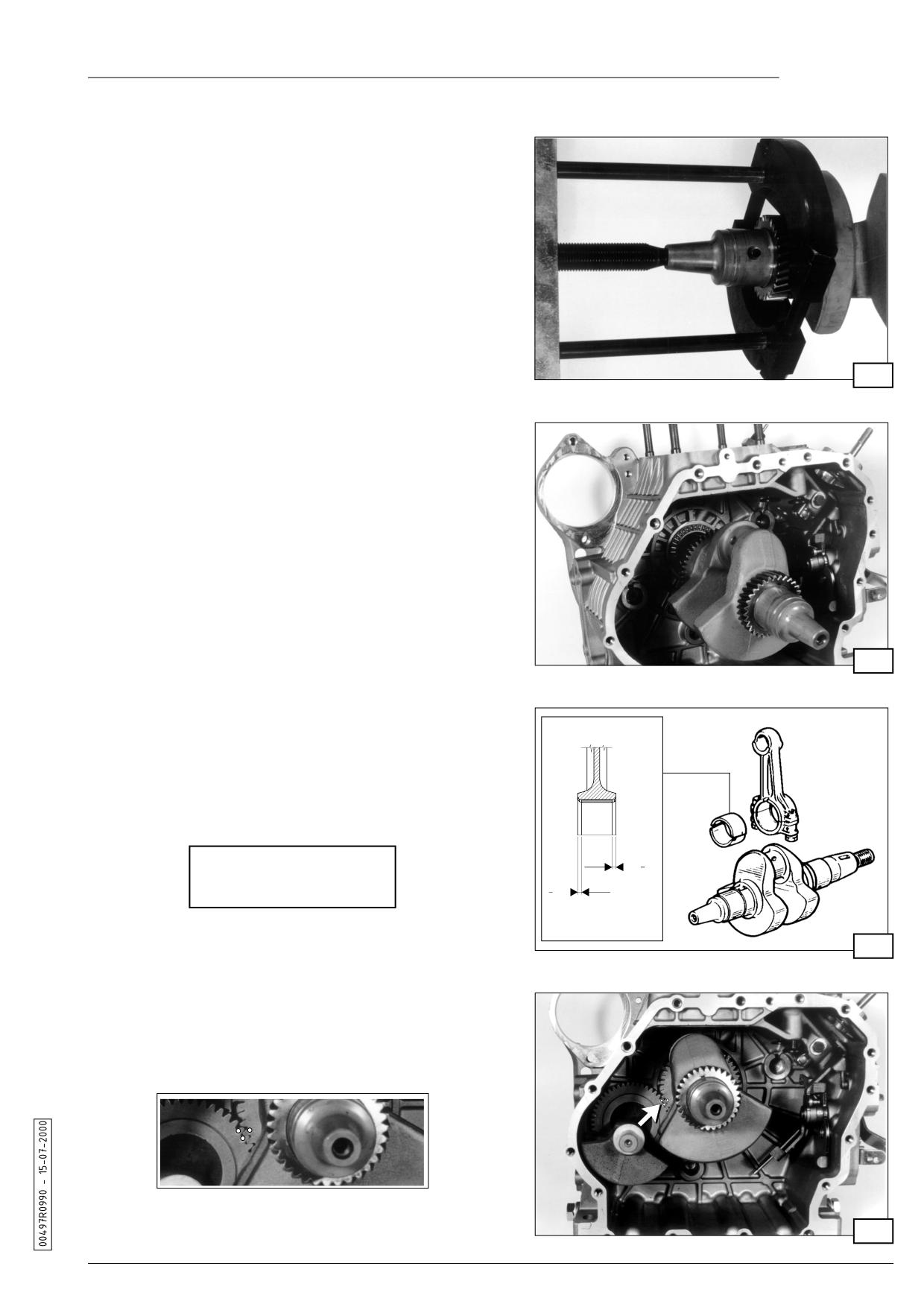
12.4 Removal and assembly of the drive shaft gear
The gear on the timing system side can only be replaced.
To demount it, use puller code 365.10 (fig. 57) or a puller
available on the market.
To assemble, preheat the gear to a temperature of about 180
to 200 °C, fit it on the shaft, taking care to ensure that the
chamfer points towards the internal part, and use the tang as
a reference.
57
12.5 Drive shaft assembly (fig. 58)
Mount the drive shaft after having fixed the first shimming
washer to the casing with Loctite 648 and after having inserted
the needle bearing and the second shimming washer.
12.6 Connecting rod - drive shaft connection
After having fitted the bearings into the small end, connect the
connecting rod to the crank pin as shown in fig. 59.
Mount the connecting rod cap with the reference numbers
matching those on the rod.
58
WARNING: for series RY120 and RY121 engines, mount the
connecting rod half bearing with the positioning mark on the
cap and that without positioning mark in the center of the rod,
RY120
- RY121
in compliance with the dimensions indicated in fig. 59.
Evenly tighten the connecting rod bolts to the following value:
A
3.8 to 3.9 Kgm
(37.3 to 38.2 Nm)
A
A = 1.7 to
2.0 mm
59
12.7 Counter-shaft
Insert the counter-shaft, matching the reference marks on the
gears (fig. 60).
60
25.0
D IESEL
12.8 Camshaft
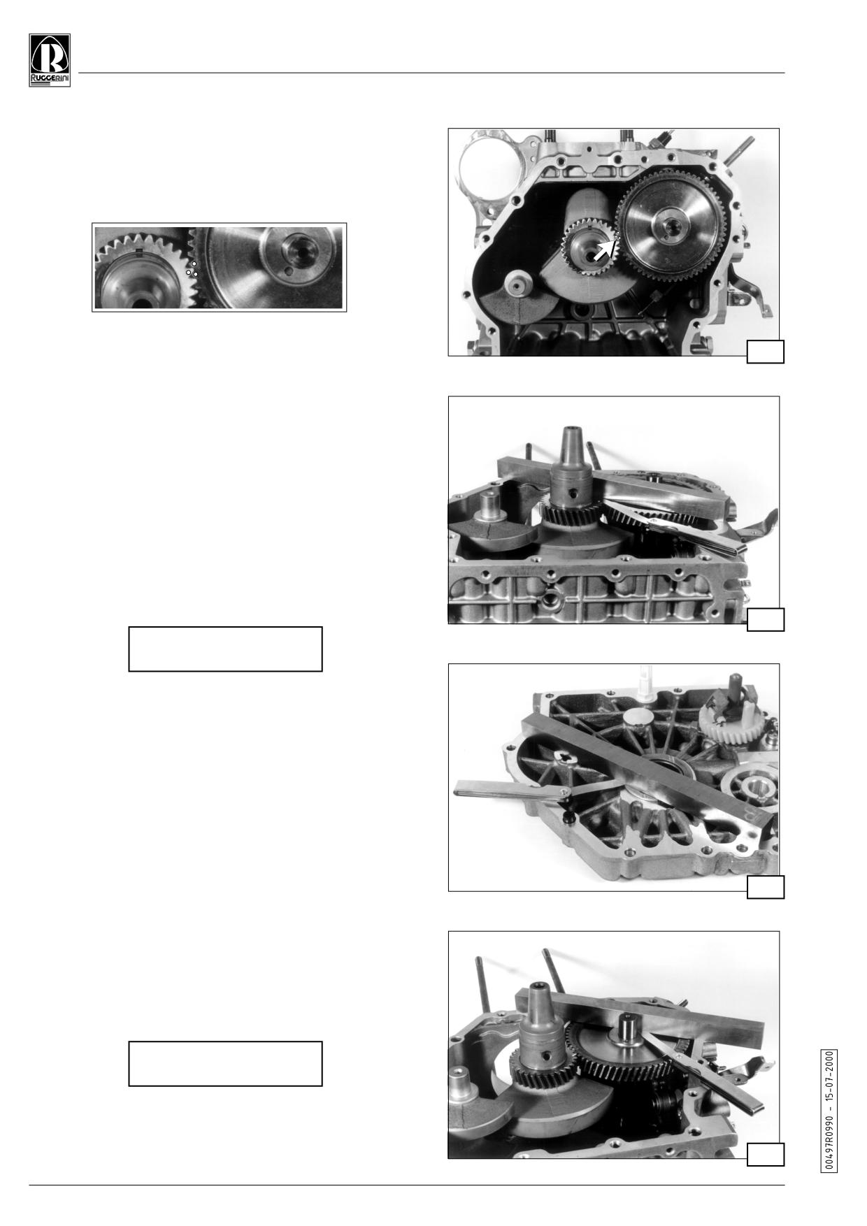
Insert the tappets into their housings on the casing. Mount the
camshaft, matching the reference marks on the gears (fig.61).
61
12.9 Play adjustment
Crankshaft float:
Place a calibrated bar on the casing, on a level with the timing
system cover retention surface and use a thickness gauge to
check the distance between the gear and bar (fig. 62). Note
down the value measured.
Place a calibrated bar on the cover of the timing system, on a
level with the engine casing retention surface and use a
thickness gauge to check the distance between the bearing
ring and bar (fig. 63). Note down the value measured.
The sum of the two measured values must be within:
62
0.10 to 0.30 mm
63
Camshaft float:
Place a calibrated bar on the casing, on a level with the timing
system retention cover and use a thickness gauge to check
the distance between the gear and bar (fig. 64). The value
must be between:
0.10 to 0.25 mm
64
26.0
service
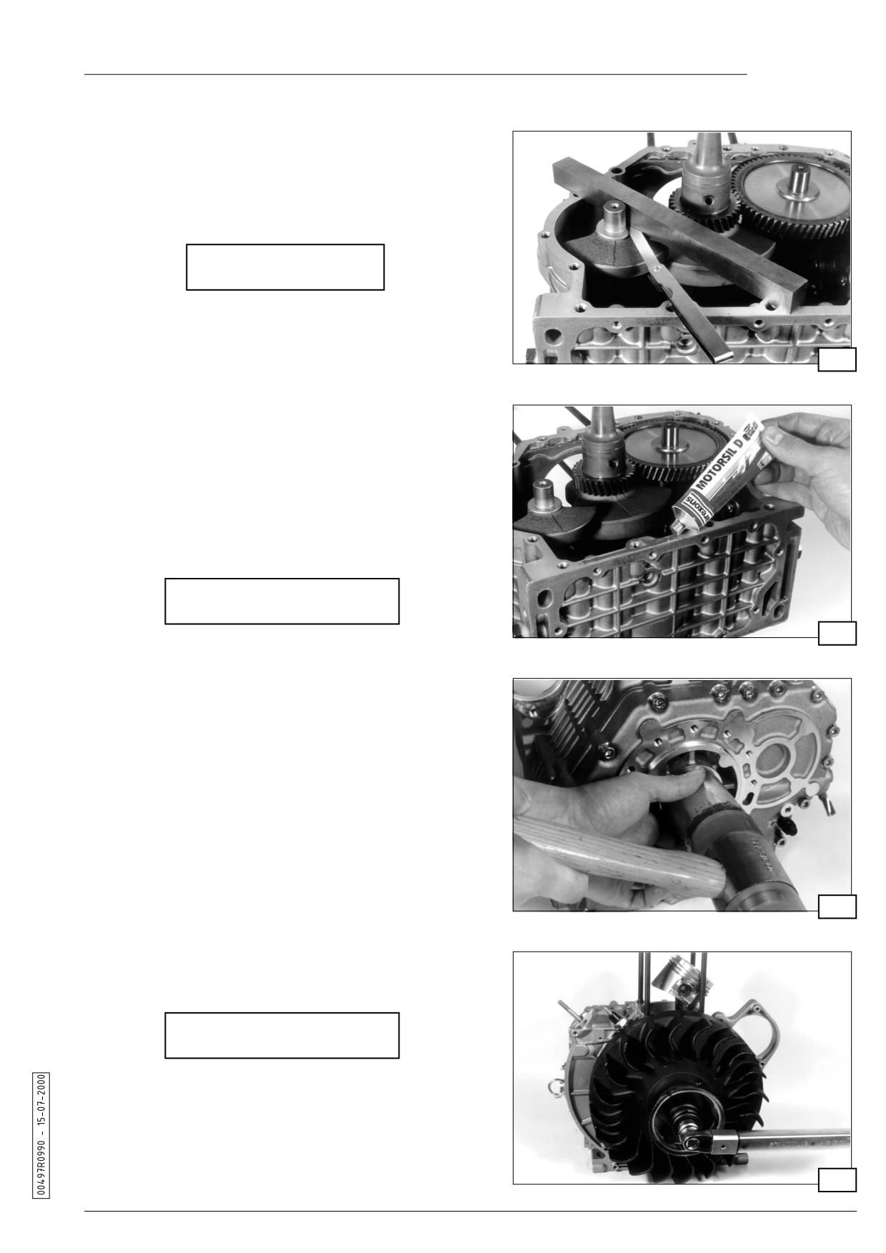
Counter-shaft float (optional):
Place a calibrated bar on a level with the timing system cover
retention surface and use a thickness gauge to check the
distance between the stop surface and bar (fig. 65). The
measured value must be between:
0.10 to 0.25 mm
65
12.10 Cover on timing system side
Spread liquid seal of the AREXON D 0036 MOTORSIL type on
the retention surface of the timing system cover (fig.66).
Place the cover on the casing.
Insert the cover fixing screws, making sure that the five shorter
ones (40 mm) are mounted in the top part of the cover. Tighten
to the following torque value:
2.7 to 2.8 Kgm (26.5 to 27.5 Nm)
66
12.11 Oil retention rings
1) Immerse the retention ring in oil for about 10 minutes.
2) Clean the housing and insert the ring with a plug, exercising
an even pressure all over the surface (fig.67).
67
12.12 Flywheel
Block the flywheel (fig. 68) and torque the nut to value:
18 to 20 Kgm (176.5 to 1961 Nm)
68
27.0
D IESEL
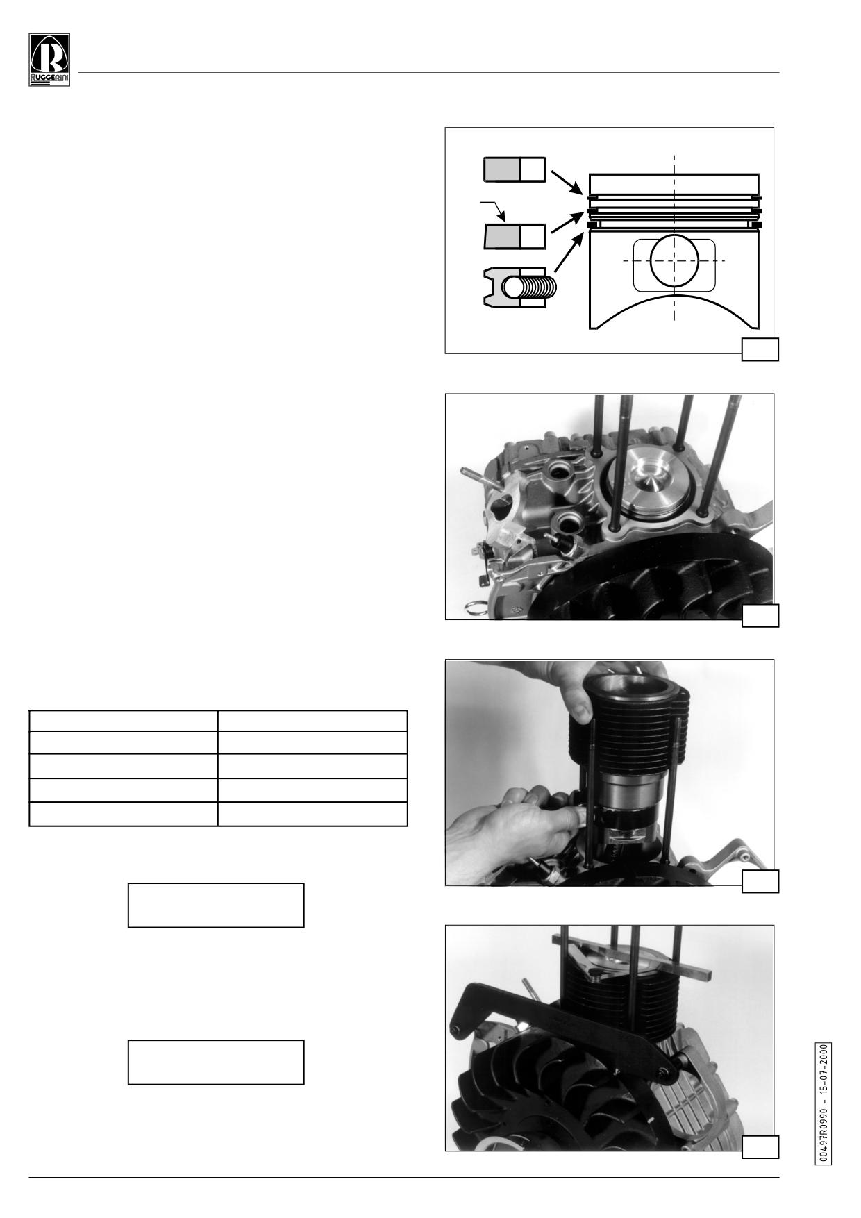
12.13 Piston
Mount the rings on the piston (fig. 69) in the following order:
1) chromium plated compression retention ring (stamped
trademark pointing upwards)
2) tapering retention ring (stamped word TOP pointing
TOP
upwards)
3) oil scraper ring (stamped trademark pointing upwards)
Position the piston so that the central axis of the combustion
chamber is aligned with the injector (fig.70). Connect the
piston to the connecting rod, slightly pressing with the hand on
the pin.
69
12.14 Cylinder
Insert the cylinder into the engine casing after having inserted
the 0.3 mm thick seal.
before mounting, turn the rings through 120°, one in relation to
the other, with the first compression ring pointing with its ends
on a level with the pin axis.
There is a chamfer to allow ring insertion on the lower side of
the cylinder. The operation is simplified by using a normal ring
mounting tool code 365.77 as indicated in fig. 71.
Move the piston to TDC (top dead center) and check that the
mark stamped on the flywheel corresponds to the reference
pointer of the tool code 366.24 (see section 12.17).
To obtain the correct clearance, use a head seal of adequate
70
thickness:
1) check the piston projection as shown in fig. 72
2) Choose the seal as indicated in the following table
Piston projection (mm)
Seal thickness (mm)
0.00 to 0.10
0.8
0.10 to 0.20
0.9
0.20 to 0.30
1.0
0.30 to 0.40
1.1
NOTE: The distance between piston crown and the
corresponding head surface must be:
71
0.7 to 0.8 mm
12.15 Head
Before fixing the head to the cylinder, fit the injector into its
housing and, after having temporarily fixed it, check that the
distance the nozzle projects from the surface of the head by
(fig. 73):
2.2 to 2.7 mm
regulate by placing copper washers between the injector and
the bearing surface on the head.
Consult sections 9.1 and 9.2 for the relative inspections and
72
overhauls.
28.0
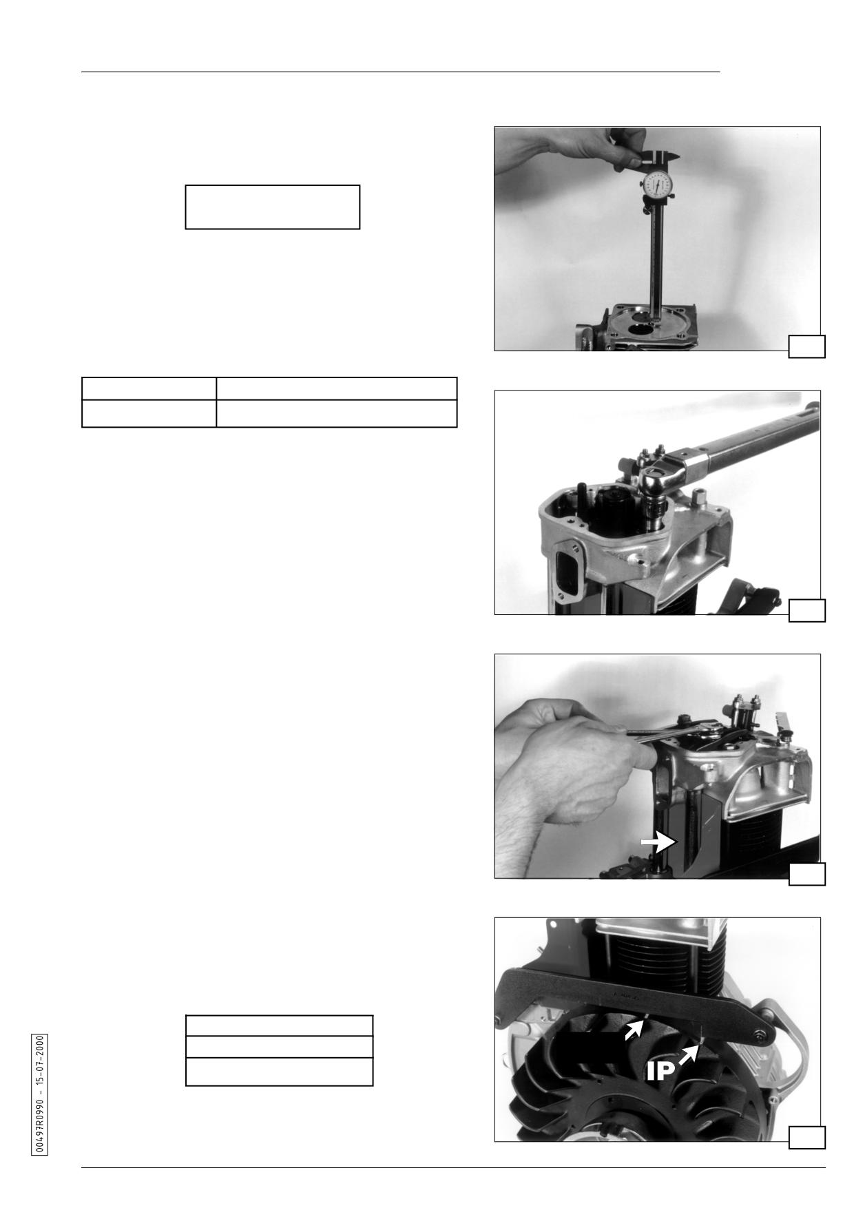
service
Insert the rocker arm casings, the partition (A, fig. 75), the
head seal and the head. Tighten the head fixing nuts evenly
and alternately (fig. 74) to the following value:
4 Kgm (39.2 Nm)
NOTE: To prevent oil leaks, apread sealant (Motorsil) on the
threads of the stud bolts and washer bearing surfaces in the
rocker arm chamber before tightening the nuts.
12.16 Valve play
Adjust the play between valves and rocker arms in either a hot
73
or cold condition, to the following values (fig. 75):
hot
0.15 mm (intake/exhaust)
cold
0.20 mm (intake/exhaust)
Since the automatic decompression device opens the exhaust
valve near TDC, play must be adjusted during the expansion
phase, a few degrees after TDC.
12.17 Injection lead
To ensure the injection lead is accurately adjusted, it is
advisable to define the shims to insert under the pump by
measuring the dimension between the pump bearing surface
and the tappet. Proceed in the following way:
74
1) turn the flywheel to the compression phase
2) insert the tappet pad into the housing in the engine block,
pointing the exhaust side towards the tappet roller (see fig.
30 page 18)
3) align the dynamic lead punch mark (IP) on the flywheel with
the reference mark of the tool code 366.24 (fig. 76)
4) using a depth gauge (fig. 77), measure the dimension
between the injection pump bearing surface and the tappet
pad.
5) subtract 51.6 mm from the dimension measured on the
gauge; the result represents the theoretic thickness of the
A
seals to insert under the injection pump.
75
NOTE: if the flywheel or a crank component is replaced, make
sure that the punch mark on the flywheel (TDC, fig. 76) and
the reference mark of the tool code 366.24, match when
the piston is at top dead center
Lead values in degrees and millimeters on the flywheel:
LEAD
IP
TDC
24°±1° (56.6 mm)
The punch marks on the flywheel indicate (fig. 76):
TDC
= top dead center
76
IP
= start of delivery
29.0
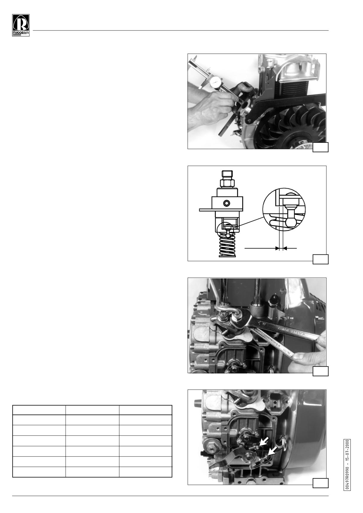
D IESEL
12.18 Mounting the injection pump on the engine
Lower the tappet in the innermost point of the engine by slightly
turning the flywheel.
Insert a seal of adequate thickness (see section 12.17 point 6).
Turn the motor stop lever to the STOP position.
Set the adjuster sleeve of the injection pump about one
millimeter from the stop position on the adjuster block (fig.
78).
Fit the injection pump into the engine block and, keeping it
pressed down, fix it in place by tightening the nut that holds
the relative bracket.
(Match the marks made during the demounting phase, see
section 8.2)
77
Warning: consult chapter 13.2 if the position of the injection
pump in relation to the casing was not marked during the
demounting operations or if a new one must be installed.
12.19 Injector and injector tube
Mount the injector on the head, inserting the copper retention
seals (see section 12.15).
Connect the injector to the pump with the injection pipe.
Warning: always use two wrenches to slacken off or tighten
injection pipes (fig. 79).
˜ 1 mm
78
13. ENGINE TEST
13.1 Rpm regulation
Fill the engine with oil and diesel fuel and allow it to warm up
for 10 minutes.
With the engine hot, adjust the idling rate (A, fig. 80) to 1,300
rpm and the peak no-load rate (B, fig. 80) to:
- 3,150 rpm for engines set at 3,000 rpm on load
- 3,750 rpm for engines set at 3,600 rpm on load
13.2 Braked engine test
Carry out the following operations after having positioned the
engine on the brake:
1) Start the engine and allow it to idle
79
2) Allow the engine to run in before checking the maximum
power
Running in table:
Time (min)
Rpm
Load
5
2000
0
15
3000/3600
0
30
3000/3600
30%
BA
30
3000/3600
50%
30
3000/3600
70%
5
3000/3600
100%
Consult the power curves in chapter 2.
80
30.0
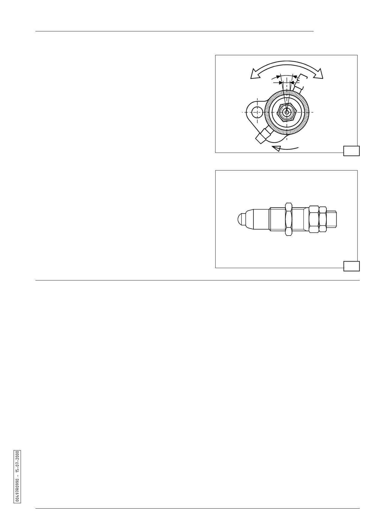
service
There may be hunting problems, slowness or misfiring if the
HUNTING RATE
RATE
injection pump is changed. Correct these faults by turning
DIMINISHES
DIMINISHES
8° MAX
MORE SLOWLY
the pump casing a few degrees in relation to the engine
casing, following the directions indicated in fig. 81.
2.5 mm
Fuel limiter.
The fuel limiter has a torque corrector device (fig. 82) that
consists of the following parts:
A) Torque corrector cap
B) Maximum power flow rate adjuster
C) Spring load adjuster
STOP
D) Locking nuts
81
The adjustments can only be made to the exhaust brake. It is
therefore inadvisable to tamper with the corrector adjuster (C
fig. 82). The setting of adjuster B (fig. 82) can only be modified
if work has been done on the injection pump or regulator, if the
D
D
engine produces a lot of smoke or has insufficient power.
82
14. STORAGE
Engines that are to remain unused for a long period of time must be prepared in the following way:
14.1 Storage for up to 6 months
· allow the engine to idle at a low rate for about 15 min.
· change the fuel filter, pour a mixture of diesel fuel and 10% AGIP RUSTIA 81 protective oil into the tank
· turn the engine over for about 10 minutes at a speed of between 1/2 and 3/4 of its normal rate so that the pipes, injectors,
pumps and filters and filled with the protective mixture
· spray AGIP RUSTIA C SAE 30 into the exhaust and intake ducts and turn the starter pulley by hand
· thoroughly clean the fins, the radiator and the external parts of the engine. protect the unpainted external surfaces with
AGIP RUSTIA C SAE 30 oil
· seal the exhaust pipe and air filter with adhesive tape
· wrap the engine in a plastic sheet
14.2 Storage periods of more than 6 months
Besides the above operations, also:
· allow the engine to operate with AGIP RUSTIA C SAE 30 protective oil
· periodically inspect the engine and make sure that there are no traces of rust or corrosion
14.3 Setting at work
· remove the protective covers
· remove the external protective coating with solvent or degreaser
· check the injector settings, the valve play. Make sure that the heads and filters are well tightened
· proceed with the normal preliminary inspections prior to starting
· if the engine has been filled with AGIP RUSTIA C SAE 30 protective oil, replace this after at least 100 hours
service.
31.0
D IESEL
15. SUMMARIZING TABLES
15.1 Couplings
Play (mm)
Limit (mm)
Camshaft and plugs
0.032 - 0.061
0.1
Compression ring opening
0.30 - 0.50
0.8
Oil scraper ring opening
0.25 - 0.50
0.8
Connecting rod and piston pin
0.023 - 0.038
0.04
Injection pump tappets and housing
0.021 - 0.059
0.1
Tappets and housing
0.005 - 0.029
0.1
Pin and piston
0.003 - 0.013
0.04
Intake guide and valve
0.030 - 0.050
0.1
15.2 Adjustments
MIN (mm)
MAX (mm)
Camshaft float
0.1
0.25
Countershaft float
0.1
0.25
Crankshaft float
0.1
0.3
Connecting rod float
0.3
0.5
Connecting rod radial play
0.019
0.046
Regulator pin float
0.2
0.3
Valve play when hot [cold]
0.15 [0.20]
0.15 [0.20]
Valve recessing
0.8
1
Injector projection
2.2
2.7
Piston projection
0.1
0.4
32.0
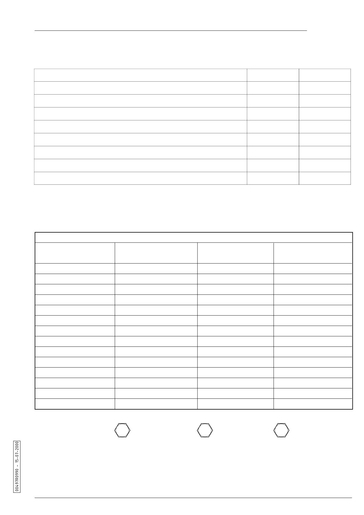
service
15.3 Driving torques
Kgm
(Nm)
Timing system cover
2.7 - 2.8
26.5 - 27.5
Injector ring nut
4.6 - 5.6
45 - 55
Injection tube unions
2 - 2.5
19.6 - 24.5
Injector bracket
0.8 - 0.9
7.8 - 8.8
Injection pump bracket
2
19.6
Head
4
39.2
Flywheel
18 - 20
176.5 - 196.1
Connecting rod
3.8 - 3.9
37.3 - 38.2
15.4 Standard driving torques
Diameter x pitch
8.8 Steel with a high % of C
R10 Steel alloys
R12 Special alloys
mm
Kgm
(Nm)
Kgm
(Nm)
Kgm
(Nm)
4 x 0.70
0.37
(3.6)
0.52
(5.1)
0.62
(6.1)
5 x 0.80
0.72
(7.1)
1.01
(9.9)
1.22
(12.0)
6 x 1.00
1.23
(12.1)
1.73
(17.0)
2.08
(20.4)
7 x 1.00
2.02
(19.8)
2.84
(27.8)
3.40
(33.3)
8 x 1.25
3.02
(29.6)
4.25
(41.7)
5.10
(50.0)
9 x 1.25
3.88
(38.0)
5.45
(53.4)
6.55
(64.2)
10 x 1.50
5.36
(52.6)
7.54
(73.9)
9.05
(88.7)
13 x 1.75
9.09
(89.1)
12.80
(125.5)
15.30
(150.0)
14 x 2.00
13.80
(135.3)
19.40
(190.2)
23.30
(228.5)
16 x 2.00
21.00
(205.9)
29.50
(289.3)
35.40
(347.1)
18 x 2.50
26.30
(257.9)
37.00
(362.8)
44.40
(435.4)
20 x 2.50
36.60
(358.9)
51.50
(505.0)
61.80
(606.0)
22 x 2.50
44.40
(435.4)
62.40
(611.9)
74.90
(734.5)
24 x 3.00
56.90
(558.0)
80.00
(784.5)
96.00
(941.4)
= 8.8
= R10 = 10.9
= R12 = 12.9
8.8
R10
R12
33.0
service
D IESEL
TABLE OF CONTENTS
1. TECHNICAL SPECIFICATIONS
5.0
11. ELECTRICAL EQUIPMENT
21.0
11.1
Characteristics of the system
21.0
2. POWER GRAPHS
6.0
11.2
Checking the system
22.0
11.3
Checking the alternator
22.0
3. OVERALL DIMENSIONS
7.0
11.4
Ring gear
22.0
4. SPECIAL TOOLS
8.0
12. ENGINE ASSEMBLY
23.0
12.1
Preparing the engine block
23.0
5. MAINTENANCE SCHEDULE
9.0
12.2
Injection pump tappets
23.0
12.3
Timing system cover pre-assembly
24.0
6. TROUBLESHOOTING TABLE
10.0
12.4
Removal and assembly of the drive
shaft gear
24.0
7. ENGINE IDENTIFICATION
11.0
12.5
Drive shaft assembly
25.0
12.6
Connecting rod - drive shaft connection 25.0
8. DEMOUNTING THE ENGINE
11.0
12.7
Countershaft
25.0
8.1
Removing the injector
11.0
12.8
Camshaft
25.0
8.2
Removing the injsction pump
11.0
12.9
Play adjustment
26.0
8.3
Removing the flywheel
11.0
12.10
Cover on timing system side
27.0
8.4
Removing cover on timing system side 12.0
12.11
Oil retention rings
27.0
8.5
Demounting the piston
12.0
12.12
Flywheel
27.0
8.6
Demounting and remounting the main
12.13
Piston
28.0
bearings
12.0
12.14
Cylinder
28.0
12.15
Head
28.0
9. INSPECTIONS AND OVERHAULS
13.0
12.16
Valve play
29.0
9.1
Head
13.0
12.17
Injection lead
29.0
9.2
Valves - Guides - Housings
13.0
12.18
Injection pump assembly
30.0
9.3
Valve springs
14.0
12.19
Injector and injector tube
30.0
9.4
Rocker arms
14.0
9.5
Cylinder
14.0
13. ENGINE TEST
30.0
9.6
Piston rings - Piston - Pin
15.0
13.1
Rpm regulation
30.0
9.7
Connecting rod
15.0
13.2
Braked engine test
30.0
9.8
Crankshaft
16.0
9.9
Oil retention rings
16.0
14. STORAGE
31.0
9.10
Lubrication circuit
16.0
14.1
Storage for up to 6 months
31.0
9.11
Checking the oil pump
17.0
14.2
Storage for more than 6 months
31.0
9.12
Camshaft
17.0
14.3
Setting at work
31.0
9.13
Tappets and rocker arms
18.0
9.14
Injection pump tappets and pads
18.0
15. SUMMARIZING TABLES
32.0
9.15
Fuel pump (optional)
18.0
15.1
Couplings
32.0
15.2
Adjustments
32.0
10. INJECTION COMPONENTS
18.0
15.3
Driving torques
33.0
10.1
Fuel circuit
18.0
15.4
Standard screw driving
33.0
10.2
Injection pump
18.0
10.3
Checking the injection pump
19.0
10.4
Injection pump calibration
19.0
10.5
Injection pump assembly
19.0
10.6
Leak test
20.0
10.7
Injector
20.0
10.8
Injector inspection and calibration
20.0
10.9
Injector demounting and remounting
21.0
Descrizioni e illustrazioni non impegnative.
34.0
service
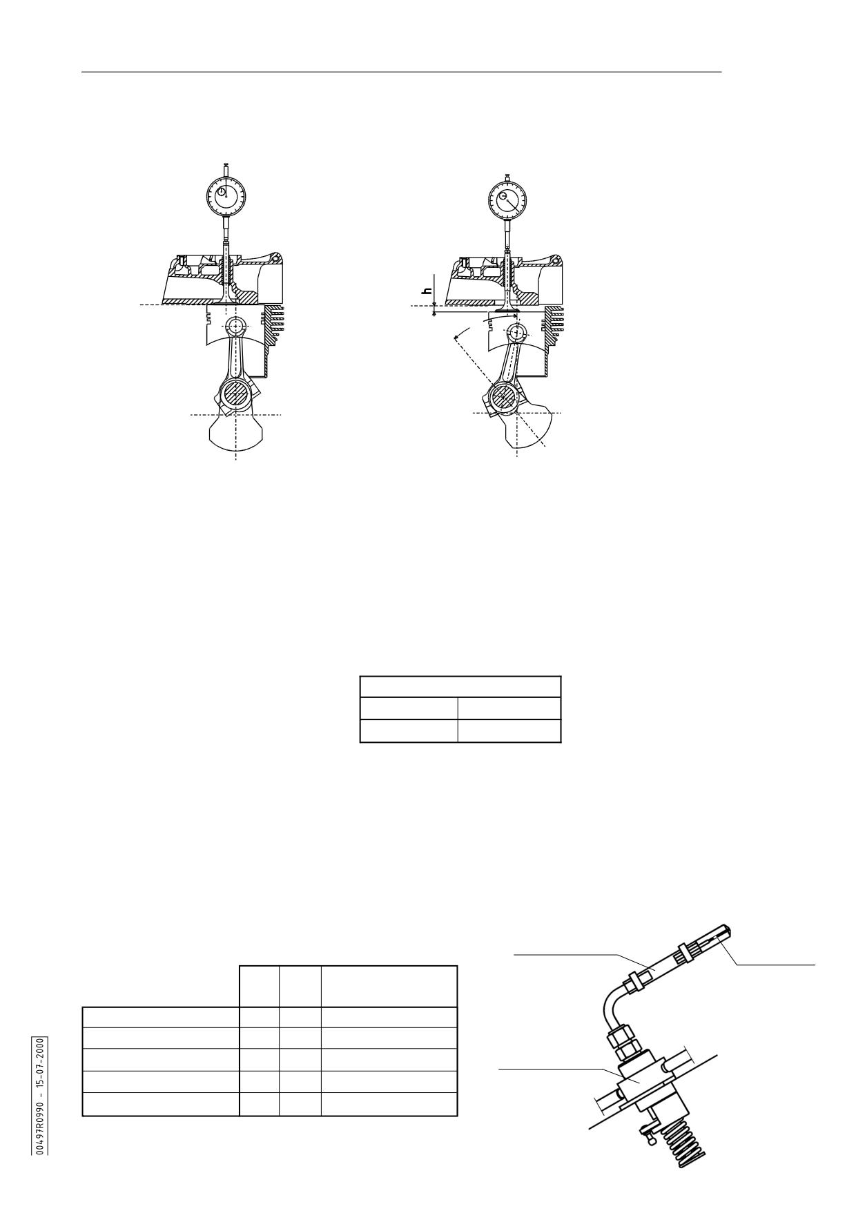
SUGGESTIONS ON HOW TO TIME THE INJECTION PUMP WHEN THE LEAD PUNCH MARKS ON
THE FLYWHEEL ARE DIFFICULT TO REACH.
(Consult chapter 12.17 on page 29 for a description of the conventional adjustment)
T.D.C. = top dead center
P.M.S.
T.D.C.
h = extent of piston lowering in
a
relation to T.D.C.
I . P.
a = angle corresponding to piston
lowering in relation to T.D.C.
FIG.
1
FIG.
2
I.P. = start of delivery
Proceed in the following way:
1) Remove the cover from the rocker arms.
2) Demount the recoil and turn the drive shaft to the valve regulation position.
(This operation is carried out by means of the fylwheel nut, using a N° 32 socket wrench).
3) Demount the intake or exhaust rocker arm, the valve spring and caps.
4) Rest the valve top on the crown of the T.D.C. balanced piston (fig.1).
WARNING: The valve slips from its guide if the piston is lowered by turning the drive shaft more than 1/4 of a pipe wrench
turn.
5) Position a comparator mounted on a magnetic pedestal or dummy injector and reset it on the valve stem (fig.1).
6) Slowly turn the drive shaft in an anti-clockwise direction and check the comparator to make sure that the piston drops about 5 mm
in relation to T.D.C. (dimension "h" - fig. 2).
7) Slowly turn the drive shaft in a clockwise direction and check the comparator to make sure that the piston rises by the values
indicated in the following table, in relation to T.D.C. (dimension "h" - fig. 2):
LEAD
h
a
4.12 mm
24°
8) Remove the injection tube and mount the capillary tube code 365.94 on the injection pump delivery fitting (fig. 3).
9) Turn the accelerator lever to the MAX position and the stop lever to about half travel.
10) Turn the drive shaft anti-clockwise by no more than 1/4 of the pipe wrench turn.
11) Pressurize the circuit by turning the drive shaft several times in an alternate clockwise/anti-clockwise way until fuel splashes out
of the calibrated hole of the capillary tube.
12) Turn the drive shaft and check the comparator to make sure that the piston drops about 10 mm in relation to T.D.C. (dimension
(quota "h" - fig. 2).
13) Shake the capillary tube until an air bubble forms inside it (fig. 3).
14) Turn the drive shaft in a clockwise direction very slowly and check the position of the air bubble in the capillary tube. A small
movement of this bubble will indicate the exact lead position. This value must correspond to the one previously read on the
comparator (see point 7). If this is not the case, add or remove seals to or from the injection pump according to the corrections
indicated in the following table:
Capillary tube
Comparative lead adjustment table
Bolla d'aria
365.94
Seal thickness for lead
h
a
correction
Value off tolerance
3.50
22°
- 0.2 mm
Value in MIN. tolerance
3.80
23°
- 0.1 mm
STD. LEAD
4.12
24°
0
Injection pump
Value in MAX. tolerance
4.50
25°
+ 0.1 mm
Value off tolerance
4.85
26°
+ 0.2 mm
FIG.
3