Teksan OPERATION AND MAINTENANCE MANUAL FOR DIESEL GENERATOR SETS
Dear User
First of all, thank you for preferring our product and company.
TEKSAN, sustains all its activities at its modern facilities, according to its principle of providing reliable products
and services at high quality with CE norms and “ISO 9001:2000; Quality Management System” certification. Your
generator set is subjected to several test and quality controls at every stage of production. There are several test
and control procedures carried out on the time interval between the very first “assembling” step and the very last
“delivery” step. TEKSAN products are also manufactured environment friendly at norms with “ISO 14001; 2004
Environment Management System” certification.
Our documents are being prepared carefully with the help of the academic education we have received and also the
knowledge and experience we have obtained from being in this business for the last 25 years. As a standard TEKSAN
documentation, the “Operation and Maintenance Manuals” for your “Diesel Engine”, “Alternator” and “Generator
Set” must have been delivered to you together with your generator set. Your duty as our customer, is to read,
understand and remember all information shared in these documents before using your generator set. This will help
you avoid any possible accidents that may be harmful for you, people around you or the generator set itself.
You may also sign for a “Periodical Maintenance Agreement” and get regular, complete and economical maintenance
and reparation services from TEKSAN Dealers, and receive good quality service for your product.
Please let us know about your wishes and suggestions in order to contribute to our product and service quality.
TS ISO 8528-5 CERTIICATE
ISO 9001 QUALITY MANAGEMENT SYSTEMS CERTIFICATE
ISO 14001 ENVIRONMENTAL MANAGEMENT SYSTEMS CERTIFICATE
OHSAS 18001 OCCUPATIONAL HEALTH AND SAFETY MANAGEMENT SYSTEMS CERTIFICATE
EAC EURASIA CUSTOMS UNION CERTIFICATE
CONFORMITY OF EUROPE
ISO 27001 Information security management system Certificate
ISO 10002 Customer atisfaction
3
TABLE OF CONTENTS
1.SAFETY PRECAUTIONS
6
1.1.General Instructions
6
1.2.Lifting and Handling
7
1.2.1.Using Slings
7
1.2.2.Using Forklift
8
1.2.3.Towing Trailer Mounted Generator Sets
9
1.3.Moving Parts
10
1.4.Hot Surfaces, Sharp Edges and Corners
10
1.5.Fire and Explosion
11
1.6.Hazardous and Corrosive Substances
12
1.7. Environmental Protection
12
1.8.Electrical Equipment and Connections
13
1.8.1. First Aid In Case Of Possible Electrical Shock Accidents
14
2. GENERAL DEFINITIONS
15
2.1.Identifying Sets
15
2.2.Generator Set
15
2.2.1 Canopy Type Generator Sets
16
2.2.2 Container Type Generator Sets
17
2.2.3 Drop Over Canopy Type Generator Sets
18
2.2.4 Mobile Generator Sets
19
2.3 Diesel Engine
20
2.4 Alternator
20
2.5 Fuel Tank
21
2.6 Base Frame
22
2.7 Vibration Isolators
22
2.8 Exhaust System and Silencer
23
2.9 Control Systems
23
3-INSTALLATION
24
3.1.Selecting Room Location
24
3.2.Ground and Platform
25
3.3.Vibration
25
3.4.Cooling and Ventilation
25
3.5.Exhaust System
27
3.6.Fuel System
28
3.6.1.Storage of Diesel Fuel
29
3.7.Electrical Connections
30
3.7.1.Starter Batteries
31
3.8.Noise Control
32
3.9.Fire Precautions
33
3.10.Earthing
33
4-CONTROL SYSTEM
34
4.1.Introduction
34
4.2.Manual and Automatic Control Panel
34
4.3.Synchronization Panels
37
4.4.Basic Procedures To Be Followed Before Operation
37
4.5. Battery Charger
38
4.6.Engine Jacket Water Heaters
39
4.7.Transfer Panels
40
4
5-MAINTENANCE
40
5.1.General
40
5.2.Maintenance of the Diesel Engine
41
5.3.Maintenance of the Alternator
41
5.4.Lubrication Oil
42
5.5.Coolant
42
5.6.Fuel
43
5.7.Maintenance of Batteries
43
5.8.Maintenance of Radiator
44
5.9.Low Load Operation
45
5.10.Long Term Storage
46
5.11. General Maintenance Schedule
48
6-TROUBLESHOOTING
49
6.1.General
49
7-WARRANTY
52
5
1.SAFETY PRECAUTIONS
1.1.General Instructions
Before installing or running the generator set, it is a responsibility for the user or operator to read the whole
documentation that is included within the generator set. (“Generator Set Operation and Maintenance Manual”,
“Diesel Engine Operation and Maintenance Manual” and “Alternator Operation and Maintenance Manual”). All the
safety instructions stated in these manuals must be provided in order for a safe operation.
The person who is in charge for installing, maintaining or using the generator set, is the only responsible for
anything that risks the safety of operation. For this reason, these people must follow and obey all the instructions
stated in all provided documentation, so that the risk of accident shall be minimized.
Because of this responsibility to take, the people who will install, maintain or use the generator set, must be
trained and authorized about the procedures for installation, usage and maintenance. Any disorder or disobeying
about these procedures, rules, instructions, methods or measures in manuals, will increase the probability of failure
and accidents that may end up with injuries or maybe death.
Pay attention to all labels and warnings on the generator set. Install and operate the generator set fully in
conformity with the related standards, rules and regulations. Furthermore, the local rules and regulations should be
followed too.
Make sure that the generator set is at OFF position before performing any maintenance, repair or setting activity. In
this way, you will be isolating the generator set from any unauthorized access.
Do not start the generator set until you are definitely sure that it is absolutely safe to run it. Under any unsafe
condition, disconnect all the battery cables.
Use required safety equipment during periodical inspections and maintenances
This manual and the appendices are integral in total. All safety instructions are clearly stated in the relevant
sections of this manual. Also remember that you can always get in contact with TEKSAN and ask for advice about
any issue that is not understood clearly.
6

1.2.Lifting and Handling
1.2.1.Using Slings
Use the lifting lugs located on the generator set, while you are trying to lift or move the generator set.
Before lifting the generator set, be sure that you have checked all the lifting lugs or any connection points for any
welding cracks, breakages, twists or rust that may cause any problem during the lifting process.
Make sure that all lifting equipment and supporting components are in a good condition, so that they can resist a
load 10% more than the gross weight of the generator set as a minimum (extra margin for any snow, ice, mud or
attached spare parts/equipment on set).
Make sure that all the lifting hooks or locks have functional safety clips and all of them are connected correctly.
Be sure to use guide ropes or equivalents in order to prevent any rotation or swing action, when the machine is
lifted and there is no contact left between the machine and the ground.
Do not try to lift the generator set if there is a strong blowing wind around.
Once the generator set is lifted, be careful about the people around and keep them at a safe distance.
Once the generator set is lifted, also be sure that the operator of the lifting machine is always ready to handle any
case of emergency.
Always be sure that the generator set is placed on a flat surface. This surface to be selected, has to be able to
resist a weight 10% more than the gross weight of the generator set. Also be sure that there is not any risk of
sliding, after you put down the generator set.
Before closing and locking the doors of the generator set, be sure that there is nobody left inside the canopy or
container.
7

1.2.2.Using Forklift
Unauthorized personnel shall not ride on forklifts.
Only trained and qualified personnel shall operate forklifts. All forklifts shall be strictly maintained in accordance
with the manufacturer’s recommendations.
Ensure that forklift has enough capacity to handle the generator set safely and properly.
Then firstly lower the forklift forks to minimum/ground level and drive the forklift forks into the forklift pockets under
the baseframe of the generator set slowly and carefully. Once the forklift forks are completely inside the pockets,
then raise the level of forklift forks slowly around 15-20 cm and so the generator set shall be lifted from the
ground. After being completely sure that the lifted generator set has no contact with the floor, then drive the forklift
carefully to the place that the generator set will be dropped off.
For unloading the forklift and putting the generator set to its place safely, lower the forks once again slowly and
safely and then remove the forks carefully out from the pockets so the generator set shall sit on its place safely.
** Forklift pockets are offered as a sales option.
8
1.2.3.Towing Trailer Mounted Generator Sets
Be sure that there is nothing wrong about the towing system including the towing bar, connection points, hooks,
pins, etc... Check the chain, brake or electrical interconnections if there is available. Also check the moving parts,
connection or interlock points of the generator set. Be sure that they will not cause any problem during this
transportation process.
Make sure that all tires on the trailer are in conformity with norms and standards and in good condition. Also be
sure that the air pressure inside these tires, is at a specified level depending on the gross weight of the trailer and
generator set. Do not change the size or type of tire without the confirmation of manufacturer. Furthermore, make
sure that all the bolts, nuts and parts are tightened with an appropriate torque.
If there are any available, make sure that all the headlights, signal lights, brake lights or the fog lights are running
properly and their covering lenses or glasses are clean and in good condition.
Do not let people to stand on the towing bar or travel on the generator set. Keep your hands and fingers away from
the tightening points. Do not attempt to pull the trailer by manpower.
If possible, choose a dry place for parking or placing the trailer. Also it is important to use wheel chocks for fixing
all the wheels.
Act in accordance with all laws and regulations that define the traffic rules. Especially be sure not to not exceed
the allowed speed limit while travelling with the trailer.
Do not drive in traffic with uncertified trailer.
** Trailer is not a standard product but a sales option.
9
1.3.Moving Parts
Keep your body (especially hands, arms and hair) and clothes away from gearwheels, pulleys, belts or other
moving and rotating parts.
Do not attempt to run the generator set, if any protection cover of fans or other moving parts is removed.
Be sure that your clothes completely fit on you, if you are working around a generator set that is running. Also tie
your hair if it is long.
Keep all the access doors closed, excluding the cases of starting up, control, maintenance, repair or service.
Before starting the generator set, be sure that everyone around is at a definite safety distance.
In order to minimize the risk of accidents due to sliding or falling, keep your hands, feet or the ground clean of fluids
like fuel, diesel, grease, anti-freeze or water.
1.4.Hot Surfaces, Sharp Edges and Corners
Avoid anyone from touching the hot grease, hot coolant, any hot surface, sharp edge and corners.
Keep your hands or any part of your body, at a safe distance to the hot exhaust pipes and gases
While working inside, outside or around a generator set, wear protective clothes and accessories like gloves, boots
and helmets.
Keep a first aid kit close to you and seek for medical help urgently in case of any personal injury. Do not neglect
any small cuts or injuries.
10
1.5.Fire and Explosion
Be sure that the fuel that will be used is a well-designed combination of appropriate ingredients, according to its
purpose of use and all related norms and standards.
Keep the floor clean around the generator set in order not to face any accidents due to slippery floor covered with
grease, battery electrolyte or coolant.
Shut down the generator set long before any maintenance activity like refuelling it, checking the battery electrolyte
level, checking or changing the lubrication oil. So that the engine can get cooled before doing any maintenance on
it.
Keep any spark, flame or other combustibles away from the generator set. Do not smoke and allow smoking
around the generator set.
Do not let any formation of waste oil or fuel layer on the generator set. Clean any dirt on the engine, alternator,
base frame or canopy with an industrial cleaner. Be sure not to use combustive chemicals for cleaning purposes.
Before connecting or disconnecting the batteries, be sure to remove the charger connections on batteries.
Remove the connections from negative (-) poles of the batteries before any maintenance. Also place a warning on
the battery for preventing any short-circuit accidents.
In order for preventing any possible incorrect connections that may be done by anyone unauthorized, be sure to
attach a warning notice on the battery connections.
Keep any cables, battery terminals or other electrical equipment in a good condition. Replace any cracked, broken
or defective cables, terminals, isolators or any electrical equipment.
Provide a proper grounding for all the conductors and electrical equipment that is directly exposed to electricity.
This will prevent the accidents due to any arc or spark occurrences caused by the electrical current flowing
through or around them.
If any leakage has been inspected on or around the fuel tank or pipes, never start the generator set before resolving
the leakage problem. Do not attempt to repair the damaged fuel tanks or pipes but change them directly with the
new ones.
Always keep in mind that the temperature of the exhaust gas, exhaust manifold and the exhaust outlet pipes is
up around 550oC. Due to this fact; provide the necessary insulation to all hot surfaces and keep yourself and any
flammable material away from these hot points.
Be sure to keep any flammable material away from the generator set before doing any welding work on the
generator set. Also take any dirty (oil, fuel, etc...) cloth pieces, chemical waste, leaf, garbage or any other
flammable material away from the generator set.
Before any maintenance or service activity, be sure that there is at least one full and well-maintained fire
extinguisher around the generator set.
If there are any trees or wood around the generator set, avoid contacts of leaves and branches with the generator
set’s hot exhaust system.
Do not install or run the generator sets in places that are not approved or prescribed as dangerous.
11
1.6.Hazardous and Corrosive Substances
The generator set must be installed and operated in outdoor or well-ventilated areas.
Do not install or operate the generator set, unless there is a proper ventilation. Also be sure that the ventilation windows
stated in the previous sections of this manual are provided.
If the generator set will be operating at an indoor place, be sure to provide a proper exhaust outlet system so that the exhaust
gases can be released outdoor. Also provide a proper ventilation window for any natural gas leakage emergency case.
Be careful that the exhaust gas outlet is not redirected to indoor places, living areas, ventilation or fresh air suction points of
any machine.
Any material used for the engine (lubrication oil, grease, coolant, battery electrolyte, etc…) are industrial chemicals, so
any of them must be kept away from any part of your body. If there is any of these chemicals on any part of your body by
accident or somehow, you have to wash this exposed part/area using plenty of soap and water.
Wear a uniform that is resistant to acid and a glass for covering you face while maintaining the batteries. If any part of your
clothes or skin is exposed to the acidic electrolyte solution inside the batteries, then wash this exposed part using plenty of
soap and water.
1.7. Environmental Protection
Generator sets have some potential risks for the environment such as lubrication oil, fuel, exhaust gas, battery.
There may be local set of rules, regulations or limitations about the usage of diesel generator sets and also about the disposal
of the environment-risky materials listed above.
It is the customer’s / user’s responsibility to be aware of these rules or regulations and also to obey and conform with these
rules while using and maintaining diesel generator sets.
Disposal Of Waste / Risky Material For Environment
• Be sure that there is no lubrication oil spilled around while changing the engine oil or keeping the used oil in your
stocks.
• Keep the engine lubrication oil that has been drained, at a safe place and be sure to deliver it to authorized
organizations for properly disposal.
• Keep also the oil and fuel filters that have been replaced from the engine, at a safe place and again be sure to deliver
it to authorized organizations for properly disposal.
• Do not throw the damaged or dead batteries to trash and again be sure to deliver them also to the authorized
organizations for properly disposal.
• Be sure to collect and keep all these wastes and damaged parts inside an isolated and fireproof waste tank.
• Be sure to prevent any fuel or oil from leaking and spilling around to environment.
• Be sure to check and conform with your “Local Environmental Regulations” before getting your generator set started
and operated.
12
1.8.Electrical Equipment and Connections
Cable classification and connections of a generator set should be made and checked by only trained and qualified
electricians.
Do not touch the electrical hardware of the generator set directly with you bare hands or with the help of any
conducting material.
Before connecting or disconnecting power cables, or before starting the generator set, make sure that the
generator set is properly grounded in accordance with all related rules and regulations.
Do not run, connect or disconnect the generator set underwater or on a wet ground. Remind the conductivity of
water.
Before establishing any electrical connection to the generator set; first stop the engine, then remove the supply
connection from the charger input, then remove all battery connections and finally remove all non-grounded
conductor connections at the load side.
Avoid touching the electrical and moving parts of the generator set with bare hands or any tool. Also be sure that
you are standing on a dry and insulated ground if you have to touch them (electrical installation or equipment) for
any repair or maintenance purposes.
Be sure to keep the insulators at the alternator output on their places. Put them back to their places right after
any connection or disconnection activity. Do not run the generator set if these insulators are not mounted on their
places.
Close and lock all the doors if the generator set is out of service, so nobody unauthorized can get in the generator
set.
Keep the towing truck and equipment at least 3 meters away from the generator set and the power cables.
Perform any repair, maintenance or service activity in clean, dry, well illuminated and ventilated areas.
Be sure that the load connected is proper, according to the loading characteristic and capacity of the generator set.
Do not load the generator set more than its loading capacity. Also ensure that the power cables used between the
load side and generator set are at proper rating and specifications in accordance with related rules and regulations.
Never connect or disconnect electrical cables or equipment in case of gas leakage on supply line or the generator
set.
13

1.8.1. First Aid In Case Of Possible Electrical Shock Accidents
If you witness an electrical accident it is important to respond quickly but with caution at the same time. So do not
touch the victim until being sure that the electricity is switched off, otherwise you may receive an electric shock
too. If you are not able to switch off the electricity, you can try to rescue the victim by using some dry and dielectric
equipment as an alternative.
After taking the patient to a safe place far from the electrical installation;
1.
Call for emergency service or any medical support.
2.
Keep patient lying down at a prone position. (A) Put the head on arms and turn it to one side for allowing any
possible fluid drainage.
3.
Remove all objects like denture, tobacco or chewing gum out from the patient’s mouth in order to provide an
ease on breathing or any possible fluid drainage. Using your palms, firmly press between the shoulders of patient. Be
sure that the patient’s tongue is released.
4.
Kneel down in such a position that your knee is near the patients head and your other foot is close to his/her
shoulder. (B)
5.
Put your hands on the patient’s shoulders and place your palms on his/her scapula.
6.
Push your arms forward in a vertical position. Slightly apply pressure (10-15 kg.) on the patient’s scapula for
2,5 seconds.
7.
Release the pressure by sliding your hands over the patient’s shoulder to his/her elbows in around 1 second.
Then lift up the patient’s arms and shoulders slightly by holding from his/her elbows. Just after holding the arms
and shoulders for a short time, push them backwards for around 2,5 seconds for stretching (C). After all, release the
patient’s arms back (D) and put your hands back onto the patient’s scapula.
8.
Repeat all these steps in order to help the patient for breathing.
9.
At the meantime someone is doing these movements for helping the patient to breathe, anyone else must;
a.
Loose the clothes on the patient for making the patient breathe easier,
b.
Keep the patient warm until the patient feels better.
10.
If the patient stops breathing, apply artificial respiration and go on doing it until the patient breathes again. It
may take up to 4 hours.
DO NOT GIVE ANY LIQUID IF THE PATIENT IS STILL UNCONSCIOUS
14

2. GENERAL DEFINITIONS
2.1.Identifying Sets
Generator sets and its main pieces (engine, alternator) do have nameplates
on them for easing the identification process for the user.
A brief information about the generator set (model codes, serial numbers,
etc...) can be found on these identification nameplates.
An example of “generator set nameplate” can be seen in the picture on the
right.
The customer / user has to provide the supplier the “serial number” of the
subjected generator set while requesting any spare parts or while applying
for a warranty case about that generator set.
2.2.Generator Set
TEKSAN produces reliable generator sets at high quality in accordance with
ISO8528 standards. Generator set specifications, options, electrical and
mechanical drawings are all recorded and followed under the unique serial
number of the generator set.
Main components of the generator set are shown in the figure below.
1
Lifting Lug
6
Earthing point
12
Turbocharger
2
Jacket Water Heater
7
Lifting Lug
13
Engine
3
Fuel Tank
8
Connection Box
14
Exhaust Outlet
4
Starter Motor
9
Control Panel
15
Radiator Cap
5
Batteries
10
Alternator
16
Radiator
6
Vibration Isolators
11
Air Filter
17
Baseframe
Figure: Main components of a diesel generator set.
15
2.2.1 Canopy Type Generator Sets
Teksan manufactures canopies for outdoor installation with the following features and specifications;
• Weather and sound proof capability,
• High level of noise reduction,
• Sheet metal structure painted with electrostatic powder paint ,
• High durability against corrosion and rust,
• Assembly of the parts is carried out with screws with no-welding, so the replacement of the damaged parts
are easier.
• Ease of transportation with lifting lugs.
• Exhaust silencer fitted inside the canopy,
• Emergency stop button fitted outside the canopy,
• Fresh air inlets for adequate ventilation of the generator set,
• Hot air outlet from the top for discharging the hot air and exhaust gas from the same direction,
• Rain cap in exhaust silencer outlet,
• Radiator filling cap,
• Cable entry area for easy installation.

2.2.2 Container Type Generator Sets
Teksan manufactures containers for outdoor installation with the following specifications;
• Interior surface of canopy is covered with non-flammable noise isolation foams.
• Improved sound insulation performance with the sound insulation cells and sections at the air inlet and outlet
of the container.
• Various container dimensions depending on the rating of the generator set.
• Exhaust silencers are fitted inside canopies. For some models exhaust silencers may be fitted on the canopy
due to limited space inside canopy. The internal structure of exhaust design is proper for a silent ambient.
• One emergency exit door that is close to the side of the radiator for providing a more easy access to the
generator. Also a cabinet door is located when transfer switch will be inside container in some systems.
• The fuel tank is put inside a separate section in the container in some models if sub-base fuel tank is not
available on the baseframe.
• Anti-vibration rubber pads mounted in between baseframe and canopy.
• There are four lifting lugs available on a standard container for lifting it from its top.
• In order to increase the strength of the container, the exterior surface is formed with trapezoidal sheets.
17

2.2.3 Drop Over Canopy Type Generator Sets
Teksan manufactures drop over canopies for outdoor installation with the following specifications;
• Interior surface of canopy is covered with non-flammable noise isolation foams.
• Sound insulation for air inlet and outlet.
• Cabinet doors on both sides, for reaching around the generator set easier.
• Transfer panel can be included inside the canopy, or it can be put somewhere outside the canopy.
• Generator should not be lifted up using the lifting lugs on the canopy. Firstly generator set must be located on the
platform and then drop over canopy must be put on it. Drop over canopy can be mounted and unmounted easily on
a generator set, so this provides the user an easier installation process.
• Drop over canopy must be fixed to the ground on the generator set platform.
18

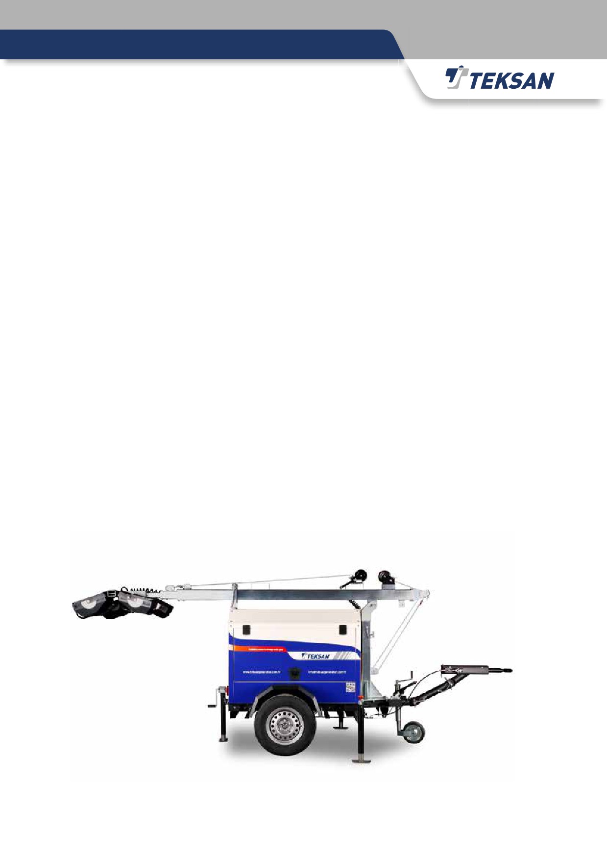
2.2.4 Mobile Generator Sets
Trailer Mounted Generator Sets & Lighting Tower
Generator sets can be supplied with trailers for mobile usage. Equipped with tires to provide full mobility services
for easy movement to the site where power is required, these generator sets can be utilized as lighting towers,
rental power, military, construction etc. applications. These sets can also be designed as ‘ultra silent’ upon
customer request.
19

2.3 Diesel Engine
Teksan uses the diesel engines those are manufactured with latest technology, in accordance with ISO3046
standards and designed for generator sets. The diesel engines used; are designed for low fuel consumption, with
4-stroke type, direct injection, with all needed limiting and level sensors, with diesel electronic or mechanical
type governor mounted on fuel pump for sensitive speed adjustment or regulation. The engines used, may have oil,
air or water type cooling systems, depending on customer request and the diesel engine. There are also oil, fuel,
air filters which are designed for heavy operation conditions, which provide the engine a long lifetime with a high
performance. All the equipment that is needed for the diesel engine for operating safely and reliably, is provided
along with the generator set.
2.4 Alternator
Alternators used on TEKSAN generator set are designed in compliance with the standards IEC600341, CEI23,
BS4999, BS5000, VDE0530, NF51100, NF51111, OVEM10 and NEMA MG 1.22.
Their insulation systems are in compliance with CE regulations and have UL certification.
They have brushless type self-excitation systems which do not require any maintenance action.
They provide a precise voltage regulation under steady-state and linear loading conditions.
Further information can be found inside the engine and alternator manuals which are
supplied together with the generator set.
20
2.5 Fuel Tank
Teksan can provide base frame fuel tank or free standing fuel tank dependent on model preferences of the
customer. Larger sets require free standing fuel tank due to needs of high fuel capacity.
Fuel tanks are manufactured of plate steel or other suitable materials.
Teksan ensures that the fuel tanks are all manufactured in accordance with relevant standards.
Teksan fuel tanks are equipped with:
• Filling cap
• Tank ventilation
• Fuel outlet valve
• Fuel return connections
• Tank drainage plug
• Sediment trapping section
• Level gauge pipe
• Float switches (Optional)
• Automatic filling (Optional)
It is highly recommended to install a fuel filter and/or a water separator on the outlet line of these fuel tanks.

2.6 Base Frame
The base frame on which generator set is placed, has been manufactured using proper steel plate or special
profiles based on the necessary dynamic, static and vibration calculations in order for providing high resistance.
Teksan produces the base frames for all ranges in accordance with international standards.
2.7 Vibration Isolators
Vibration insulators are used in order to decrease the negative effects of vibrations caused by the rotational
movement of the engine and alternator. These insulators which also prevent the vibration to be transferred from
base frame to the ground, are placed between engine/alternator and base frame. Specially chosen vibration
isolators are mounted between the engine, alternator and base frame. Alternatively in bigger generator sets,
vibration isolators are mounted between the base frame and floor.
22

2.8 Exhaust System and Silencer
An exhaust system should be designed to decrease the noise coming from exhaust manifold and dispel the
exhaust gases to the atmosphere. Exhaust system consists of flexible compensator that absorbs vibration and
expansion, steel pipes, bend, silencer and mounting equipment. Further details on exhaust systems can be found in
“Installation” section of this manual.
2.9 Control Systems
Various control systems are developed for ensuring the protection of the generator set against failures, load
transfers and the reliability of the operation for the generator set.
Control system designs can vary according to the customer requirements and assembling requirements. The main
types of control systems are Manual, Automatic, Standby, and Parallel working systems. All control systems are
mounted on steel panels containing a lockable door for easy reaching and service.
Further technical information about the control systems of the generator sets can be found in “Control Systems”
section of this manual and the manual of the controller.
23

3-INSTALLATION
3.1.Selecting Room Location
The selection and preparation of the location that the generator set will be placed is the most important step of
installation. So please make sure that the generator set is installed at a place that is selected and prepared fully in
conformity with the instructions in this manual. Also remember that you can call us for any further information of
confirmation about this issue.
If the generator will be placed on an upper floor not the basement or ground, the responsibility of static load
distribution belongs to customer. The customer should get an approval from an authority about this issue before
installation.
Install generator set in such a place that it will not be directly exposed to harsh environmental conditions as rain,
snow, hail, flood, humidity, excessive sunlight, extremely low or high temperature, dust, soil, sand or wind.
The place that the generator set will be installed must be, clean, dry, well illuminated and ventilated, free of
corrosive or conductive pollutant substances like dust, lint, smoke, oil vapour, exhaust smoke, etc...
Be sure to leave enough blank space around the generator set, in order to ease future maintenance or repair
activities Remember that it can be necessary to disassemble the main parts like engine, alternator or the base
frame in some cases.
The base ground that the generator will be settled, must be clean dry and must have a well drainage system.
Put the generator set at such place that nobody unauthorized can access it, or at least take necessary precautions
about it.
Place generator sets at such places that they will not be effected by the operation of any other machines.
Do not install or run the generator set at any place that has any possibility of risk in terms of safety of operation.
Also provide the necessary precautions (canopy option) or protections against bad weather conditions if it will be
placed outside.
The doors of the room that the generator set will be placed in, must be at an enough size for the main parts
(engine, alternator, radiator, etc…) to pass through. Also ventilation windows can be built portable or mobile for
this purpose.
24
3.2.Ground and Platform
A generator set can be placed on foundations like platform, soil, building or steel construction. The weight of the
generator set must not be more than the load carrying capacity of the ground.
It is recommended to build a concrete (strengthened with iron) platform for the generator set. Generally, the
platform is built at same horizontal sizes with the generator set and around 150-200 mm. thickness. A platform
built at a proper size depending on generator set size, will prevent the set from moving and reduce the negative
effects of vibration on engine.
If necessary, the platform can be constructed with such technical specifications that the floor is completely
insulated from the generator set against the negative effects of vibration.
If the generator set will be placed in such places that have the risk of flooding, then the thickness of the platform to
be built must be 300 mm. at least. This will ensure a dry and safe operation area for generator set and the people
working on it.
It is recommended to build standalone platforms for every single generator set. It also should be built separately
from any other building structures as other platforms, walls, etc..
3.3.Vibration
TEKSAN generator sets are designed for the minimum vibration transmission to the ground. For this purpose, rubber
vibration insulators are placed between the engine/alternator and the base frame. In applications with higher power
ratings, the insulators may be placed under the base frame for more efficiency in terms of vibration insulation.
If the generator set is placed on an upper floor, this vibration analysis of the generator and the base ground must be
done more carefully. In these types of applications, special insulation system designs may be needed with special
insulators. The base ground has to withstand the total weight of the generator set, and its accessories and the
negative effects of the uninsulated vibration.
Get the generator set fixed tightly to the ground or platform with steel connection bolts in order to prevent it from
moving around and giving damage to the electrical installation, fuel line, exhaust system, or any equipment around it.
3.4.Cooling and Ventilation
The heat radiated by engine can cause high temperature changes which can affect the performance of the generator
set.
The fresh air incoming, must be clean and cool as possible. Thus the performance and the lifetime of the engine
will be increased. This fresh air can be supplied directly from the installation area, but sometimes it may be
necessary to build ventilation channels and bring fresh air from outside.
Also ensure that the fan between the radiator and the engine can easily push out the hot air caused by the engine,
alternator or the radiator. This way the room can be ventilated and the generator set can be cooled efficiently.
At least two ventilation windows must be built for air intake and outlet. The fresh air intake window should be just
before the alternator and the hot air outlet window should be just after the radiator.
25

Ensure that hot air is being removed from the generator room with a flexible duct connection.
The cooling air flow required can be provided by calculating the dimensions of the air inlet and outlet louvers.
Windows area of the room should not be less than the area of radiator matrix. If possible, the air inlet and outlet
area should be %150 of the radiator matrix.
In order for the protection of air channels, stationary or moving shutter systems can be built within these windows.
For an automatic generator set; an automatically moving shutter system which is designed to open automatically
when the engine starts, is the best solution for this purpose. However, manually opened moving shutters can be
acceptable in some manual mode generator set applications.
The layout drawing below, is just showing a typical generator set installation.
It is for guidance purpose only. Every generator set installation case or design
must be studied carefully and individually.
26
3.5.Exhaust System
While designing an exhaust system, avoiding back pressure is very important. Excessive exhaust back pressure can
contribute to poor engine performance and increasing working temperature.
If any twist or curve is needed on the exhaust line, be sure that the radius of the elbow used on the turning point is more than
the 150% of the inner radius of exhaust pipes.
The design of an exhaust system is mainly dependent on site, room or building in which the generator set is settled. But be
sure to use the shortest and minimum curved path for piping, in order for minimizing the back-pressure.
Make sure that all piping is tightly fixed, supported and kept at a safe distance from places with too much vibration. Since the
exhaust pipes will heat up to very high temperatures, put them at least 250 mm. away from any flammable material. It is also
recommended to cover or coat the exhaust pipes with high-thermal isolation materials.
At the end of vertical exhaust lines, there must be used a rain protection cap, which can be easily opened with the gas
pressure at the exhaust outlet.
At the very lowest point of any vertical or horizontal exhaust lines, there should be an outlet for draining water out from the
line. Thus no water can reach into the silencer or engine.
Placing the muffler at a closest possible location to the engine, will help you decrease the sound level in exhaust pipes. There
may be placed another muffler at the end of the line, if the exhaust line is too long. Every engine must have its own, separate
exhaust system. No multiple engines shall be connected to a single exhaust line system. Because the exhaust gas, soot or
the condensation inside exhaust lines can be harmful for any engine when it is not running.
The exhaust line system should be integrated with the exhaust outlet of the engine with a flexible connection.
Breathing exhaust gases is harmful for human health, it may even be deathful. Also exposure to the high level noise caused
by the engine, may cause permanent hearing problems. So the exhaust system of a generator set must be designed and
installed well. Any staff around the generator set, should wear ear plugs. The generator set should never be operated with an
incomplete exhaust system.
The exhaust outlet points must be selected carefully in order for ensuring that the exhaust gas coming out from the engine,
does not go back in through the fresh air inlets. These outlets must not be put into any closed areas, passages, corridors, air
channels, ventilation or illumination spaces of buildings, open or closed balconies, elevator hoist ways, any place in that the
flow of the exhaust gas may be blocked by the wind or anything else, any place that supplies fresh air for any other machine,
the yards between the buildings and especially the habitats of any living creatures.
27

3.6.Fuel System
Main purpose of the fuel system is to supply clean fuel into the diesel engine continuously.
Ensure that the fuel system has been designed correctly and with suitable materials.
It is recommended to use a fuel filter and/or a water separator at the fuel tank outlet line.
Here are some important points to be considered while designing a fuel system properly;
• Using of suitable materials manufactured for fuel
• The distance between the fuel supply and return points/lines of a fuel tank, should be at a proper level around
300 mm. at least.
• Fuel pipes or lines should be designed and built with seamless black steel, proper plastic or copper pipes.
Galvanized or any improper type of pipes should not be used on fuel lines.
• The inner walls of the tank must not be painted or coated.
• The hoses to be used on fuel lines, must be selected properly and carefully.
The fuel to be used should be clean for a reliable operation and longer life time of the engine.
Auxiliary fuel tanks can be used if fuel pressure value caused by the main fuel tank’s location is out of producer’s
pressure limits.
Fuel level in the tank should not be at a height 4 meter higher or 3 meter lower than the fuel lift pump. Valves,
check valves or any other equipment must not be installed on the fuel return line between engine and fuel tank.
Allowed maximum fuel inlet temperature given by manufacturer should be taken into account while designing a
fuel tank or a fuel line. The rise of fuel temperature causes some changes on fuel viscosity, density and combustion
quality, so engine performance and exhaust emission will be affected negatively.
Since the fuel supplied to the engine should not consist any air inside it, the fuel lines must be designed so as not
to keep air inside.
Warning!
Do not allow smoking or any existence of sparks/flames around the fuel tank, fuel line or the engine.
1.
Fuel Tank
2.
Strainer
3.
Fuel Filter
4.
Fuel Filter Ass’y
4.a. Fuel Water Drain Plug
4.b. Air Bleeding Plug (For fuel filter)
5.
Fuel Pipe Connector
6.
Injection Pump
7.
Injection
8.
Fuel Pressure Relief Valve
9.
Fuel Return Pipe
10.
Fuel Feed Pump
28
3.6.1.Storage of Diesel Fuel
The most preferred method for providing a continuous fuel supply for the engine is fuel storage in tanks. The fuel
tanks can be installed under or above the ground.
There must be an air outlet point on the main fuel tank. The air pressure occurring while filling the tank and the
vacuum occurring during the fuel usage will be emptied by this air outlet point. Also a valve or a drainage point
must be used at a bottom point of the fuel tank, in order to be able to drain the water that may occur because of
condensation.
The fuel tank should be buried at a proper depth, so that the fuel should be protected against the frosty climate
conditions.
Another important point to be taken into account while using a main fuel tank is this; the difference of height
between the main and daily tanks. Noting that the standard electrical fuel lift pumps have a maximum pumping
capacity up to 5 meters, the difference of height between 2 tanks should not be exceeding this pumping height
capacity of the pump. Also note that too much use of horizontal pipes or elbow pipes will be decreasing the
fuel pressure on the suction line. For all these reasons; the locations of the fuel tanks and the piping to be done
between them, should be calculated and established well and carefully. The size of the fuel supply and return lines
should never be less than the sizes of the fuel connecting points on the engine and even they may need to be
increased to larger sizes in case for long-duration operations or in case of low ambient temperatures.
Fuel line pipes should be made from steel or a material suitable for petroleum. Do not use galvanized pipes. Tank
over flow pipe must be made from the same material and must be one size larger.
The fuel return lines should always enter the tank from a point above than the highest fuel level expected and there
should be no interruptions or valves on the fuel return line. In order to avoid any possible airlock problems, the fuel
return line should be designed and piped with minimum length and with minimum elbow/bending points. Also in
order to be sure that the fuel supplied for the engine is clean enough, the fuel to be supplied to engine should not
be taken from a height lower than 50 mm the base of the tank.
In order to avoid any possible risks to be caused by the vibrations on the generator set, the fuel lines should be
built with flexible pipes at the inlet points of the generator set.
29
3.7.Electrical Connections
Electrical connections must be designed, made and repaired by qualified and trained technicians.
All electrical connections and wiring must be done in compliance with the diagrams or the drawings provided by
TEKSAN.
All the connection, wiring and grounding processes must be made fully in compliance with the related international,
national and local specifications, standards, rules and regulations.
All the cables that will be used for wiring, must be selected at proper ratings and specifications according to the
current, voltage, temperature values and the wiring method.
All the electrical connections on the generator set must be made by using flexible cables. This will protect the
electrical equipment like conductors, alternator or circuit breakers from the negative effects of the vibration caused
by the engine.
If it is not possible to use flexible cables directly, then use a terminal box close to the generator set and make
flexible connections to this terminal box.
All connections must be checked very carefully before commissioning the generator set. Checking the connections,
conditions and phase orders of all cables, is very important for automatic and synchronous generator set
applications.
Control panels are specially manufactured to be mounted on the wall.
The connections between the generator set and the load distribution panel, must be protected against any possible
overcurrent and overloading problems by use of fuses or circuit breakers.
It is important to load the generator set under balanced loading conditions. If the load connected to one phase is
much more or less than the other two phases and the difference between them is more than 30%, then this will
cause overheating issues on the alternator windings or any other failures on 3-phase systems.
Be sure that the current drawn from all phases do not exceed the rated and calculated amount.
There are different types of loads which require special consideration and because of this, before connecting the
generator set to an existing electrical system, the system may be required to be revised.
Power factor (cos Ø) of the load connected, must be well determined. If it is inductive and lower than %80
(0,8) then it will cause overloading problems on the generator set. Capacitive power factor values, may cause
overvoltage problems on alternator windings.
The power factor must be inductive and at least %80 (0,8) for providing the optimum operating conditions for
generator set.
In order for having the power factor at a desired level, it may be necessary to use additional power factor correction
systems.
However, the power factor correction system must be well-designed so that the power factor can stay in the
desired limits. If the power factor becomes too capacitive, it may cause voltage instabilities and over voltage
problems.
30

3.7.1.Starter Batteries
The electrical resistance on the starting circuit, is a very important parameter for the operation of the diesel engine.
Therefore, the batteries must be placed at a closest possible location to the generator set. This way the battery
connections will be shorter and the resistance of them will be lower. Also any loose connections must be checked
and fixed for this same purpose. (The batteries must be placed at a serviceable and accessible location.)
Batteries must always be maintained well and kept in a good condition, so that the generator set can be ready to
run at any time. Maintenance activities to be done on batteries are briefly explained in the relevant sections below.
Connecting and disconnecting
While connecting battery cables, first connect the positive (+)
terminal, then connect the negative (-) terminal.
While disconnecting battery cables, first remove the negative (-)
connection, then remove the positive (+) connection.
Cleaning
Keep the batteries clean and dry. Any dirt or oxidation left on
the battery, terminals or connections will cause discharge and
voltage drop on batteries.
Remove and clean the pole heads while maintenance, use a
wire brush for cleaning the oxidation. Reconnect the cables
tightly back to the poles and use grease on these connections to
postpone the oxidation.
ATTENTION
The batteries must always be kept under a buffer charge.
The batteries on the generator sets that will be stored for a long
time, must be removed and kept charged. Otherwise, the battery
plates will be corrupted and the batteries will be out of service.
31
3.8.Noise Control
Reducing the sound level is a key factor in today’s generator set technologies. TEKSAN generator sets are
designed and manufactured for providing an optimum sound level by regarding this fact.
Extra additional equipment may be installed to the generator set systems for minimizing the sound level. Some
of the precautions taken against high sound levels are, sound insulated canopies or rooms, exhaust silencers,
acoustic shutter windows or hoods.
The solutions and precautions against high sound levels are really dependent on varying environmental conditions.
So it is strictly recommended to get professional help when designing special sound reduction systems.
The sound level of a non-insulated diesel generator set is around 100-110 dB from 1 meters. The lowest possible
sound level (also by regarding the economic facts) in generator set applications, is around 65-75 dB. Sound level
reduction is a really important parameter for generator set applications used in hospitals, schools, residential areas,
offices etc…
Exposure to a sound level higher than 85 dB for a long time, may cause hearing problems. So it is recommended to
wear ear plugs around a running generator set.
Teksan generator sets are met the noise level norms given in EU 2000-14-EC standards which is valid for the
generator sets under 500kVA.
3.9.Fire Precautions
Take all the precautions stated in section “1.5” (Fire and Explosion) against any fire and explosion possibility.
There must be an emergency escape route and scenario in case of any fire and explosion possibility.
A fire alarm system and an extinguisher in accordance with the legal regulations and standards about fire and
explosion, must be provided around the generator set.
The room in which the generator set installed, must be free of any flammable material or any accumulated garbage
by considering any fire possibility.
The fuel line must be adequately secured with free fall type shut of valves.
Do not allow smoking in the room that the generator set is installed in. Also keep any arc, spark or flame away
from here.
3.10.Earthing
In many electrical systems, the non-active parts and the parts connected to these non-active ones, must be
attached to the ground with the help of a conductor or an electrode. This principle is called is called earth
grounding.
The parts and the equipment that are directly exposed to electrical voltage, must be well-insulated in order to
ensure the durability and safety of the electrical system and staff around it. However there can be some electrical
failures due to defection, corrosion, leaking points on these insulation systems.
Non-grounded conductors in an electrical system, may be a risk for both the system and the people around it. If
all the equipment is connected to each other and to the ground properly, then any leakage on system can flow to
ground through this connection and will not cause any problem.
The grounding must be done in accordance with the related international and local regulations.
The grounding resistance must not be more than 20 Ohms.
The electricity may be harmful for human beings if it is rated more than 15 mA and 50 V.
The electrodes buried to the ground for grounding purposes must be at least 20 meter
away from another electrode.
33
4-CONTROL SYSTEM
4.1.Introduction
Programmable microprocessor based controller units are used in TEKSAN generator sets as a standard. These
controllers are capable of monitoring any electrical or mechanical changes or parameters on the generator set.
They also provide all necessary mechanical and electrical protections for the generator set.
The control systems in general, allow the user to run or stop the generator set. They also monitor and control the
measurement and protection circuits installed on the generator set. Since the controller unit is programmable, it
also provides flexibility in terms of usage under different conditions.
The control panels used on TEKSAN generator sets, are manufactured using A1 quality steel sheets and
coated with electrostatic powder paint in order for preventing corrosion. Manual (TJM), automatic (TJA) and
synchronization (TJPS) control panels are manufactured as a standard in TEKSAN. But it is also possible to design
customized control panels for different purposes or scenarios of usage.
Further details about the controller unit can be found in the additional manuals provided with the generator set.
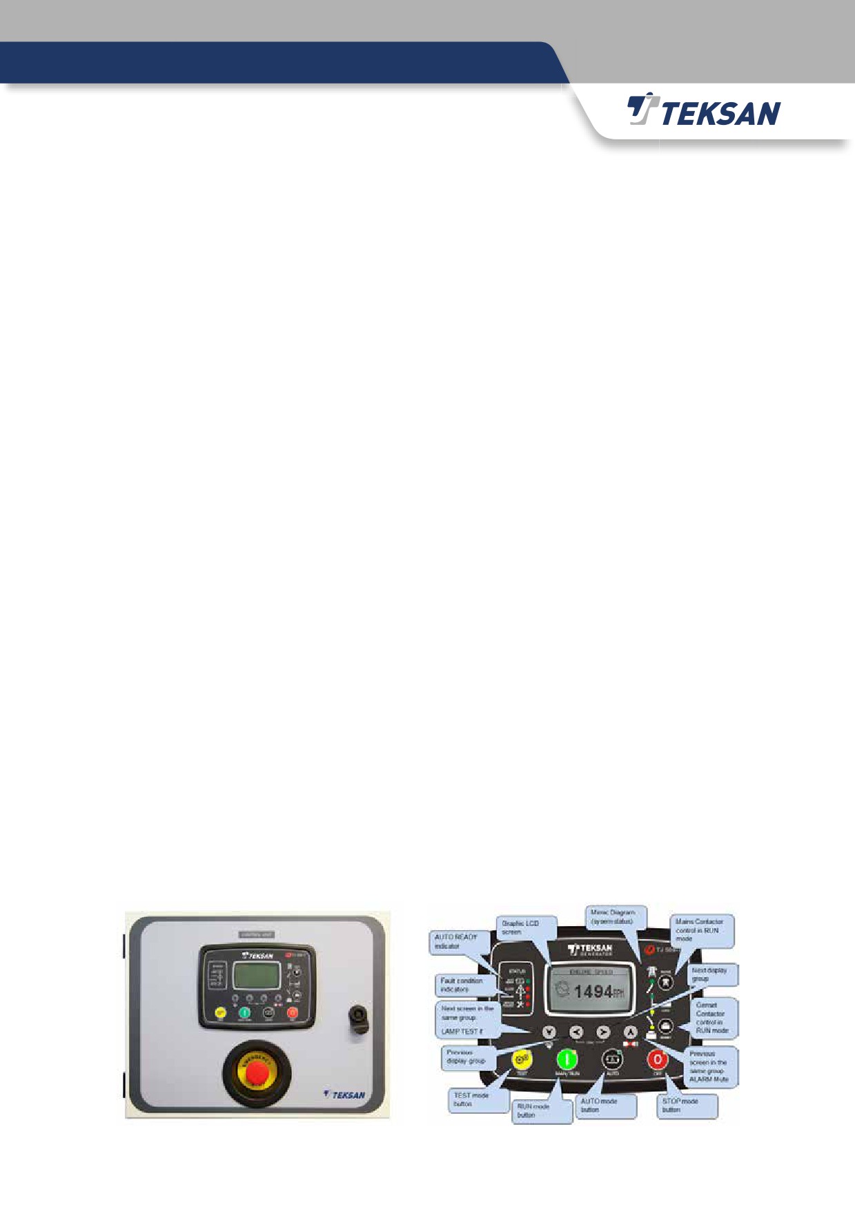
4.2.Manual and Automatic Control Panel
Automatic control panels are used in applications in which the generator set is a secondary/back-up power source
for the mains power in order to ensure that the generator set starts and supplies power when the mains power
gets off.
Manual control panels are used in applications in which the generator set is a primary/main power source and they
start and supply power when it is necessary and when the generator set gets started manually.
In both scenarios and panels, the microprocessor based TJ509-T controller manages all needs to be done like;
“monitoring the mains power”, “starting or stopping the generator set depending on the status of mains power”,
“protection of engine/alternator or any other equipment on generator set system”, “transferring the load between
mains and generator set”.
The modes of operation can be changed by pressing the relevant button on front panel and changing the operation
mode while a generator set is running, results in a behaviour change on the generator set depending on the
operation mode selected. For example; if “MANUAL/RUN” mode is selected, the controller gets into manual mode
and any process like running the generator set, opening/closing the mains/generator contactors requires manual
interference.
STOP: This mode is used for stopping the generator set or keeping it stopped at rest. Once this mode is selected
on controller; the generator set does not run and stops if it is already running. Then the generator set contactor
gets opened and the mains contactor gets closed for transferring the load to mains and supplying the load from
mains.
When the STOP button is pressed once, the controller starts the usual “stopping sequence” and stops the engine
after an “engine cooldown” process. For stopping the generator set immediately, the STOP button should be
pressed twice.
34
AUTO: This mode is used for running the generator automatically and transferring the load between mains &
generator set automatically.
Once this mode is selected on controller; if at least one of the phase voltages at the mains side gets out of
configured limits, then the mains contactor gets opened and the engine starts cranking for pre-configured times
and with pre-configured intervals. The controller stops cranking right after the diesel engine gets running. Then
when all the generator phase voltages rise and get up to a pre-configured level, the generator set contactor gets
closed after “engine heat up” and “contactor” timers and finally the load gets transferred to generator set from
mains and it begins to be supplied from generator set.
After all phase voltages on the mains side, get back into pre-configured tolerance limits again, the controller begins
to count down a “mains waiting timer” just to be sure that the mains voltages are back and proper again. Then
the generator set contactor gets opened, mains contactor gets closed and the load begins to be supplied back
from mains again. After the load is transferred back to mains successfully, the controller stops the engine after a
“cooldown timer”. Once the engine is stopped finally, the generator set gets back to its “standby” rest position for
waiting next mains failure.
If the operation of the generator set is being blocked by a weekly schedule, then the AUTO led will flash, and the
operation of the generator set will be as in the STOP mode.
TEST: This mode is used for testing the generator with or without load while the mains is still available. Once this
mode is selected on controller; the operation of the generator is similar to the AUTO mode, but the mains contactor
will not get opened if the mains is available. And if the mains is not available, the mains contactor gets opened and
the generator set contactor gets closed.
When the mains is back on again, the load gets transferred back to mains again, but the engine keeps running
unless another mode is selected. For stopping the engine in such a case, another mode of operation (AUTO or
STOP) should be selected on controller.
RUN: This mode is used for running the generator with or without load while the mains is still available or if there
is no mains at all. Once this mode is selected on controller; the engine will get running. For transferring the load
between mains and generator set in this mode, the contactor buttons on front panel should be used for manual
operation.
35
TJ509-T Controller
•
Improved firmware and software specifications and skills,
•
Exact same dimensions with TJ507 or TJ509, (This way it can easily be replaced with them directly.)
•
AMF (Auto Mains Failure), ATS (Auto Transfer Switch), RS (Remote Start) and EC (Engine Controller) modes of
operation,
•
8 digital outputs (2x16A contact, 6x10A BAT+ control output,
•
8 digital inputs, (All programmable)
•
7 analogue inputs, (All programmable)
•
J1939 CANBUS port,
•
MPU (Magnetic Pickup Unit) input,
•
USB port, (for establishing a PC connection.)
•
RS232 and RS485 ports (for modem connection, 2400-115200 changeable baud rate)
•
Digital input/output extension ports, (up to 4 modules x 8 terminals = 32 input/output)
•
History log,
•
Several language options,
•
Operating Temperature: -20°C to 70°C (-4 to +158 °F),
•
Storage Temperature: -40°C to 80°C (-40 to +176°F),
•
IP54 protection at front side, IP30 protection at back side,
•
Hi-temperature resistant ABS/PC (UL94-V0) case,
•
Remote monitoring capability with use of a GPRS modem. (DKG090)
•
Ethernet port, (10/100 Mb)
•
USB host port (for USB storage devices or GPS)
•
Remote monitoring capability by itself, (via its RS485 or ethernet ports)
•
Embedded Web Server, Modbus-TCP/IP, SNMP, Rainbow Plus and Rainbow Scada features via its ethernet port.
•
Long term data (history log) storage via its USB host port. (with use of a USB drive)
Accessories / Additional Equipment
External GSM-GPRS Modem (DKG-090)
• DIN rail mounted, (same size with 2 pcs. of fuses)
• Quad-band GSM/GPRS (850/900/1800/1900MHz)
•
12/24 V DC supply options,
•
Resistance to possible high voltage shocks around the generator set,
•
Supports E-Mail and SMS sending
•
Connects all types of TJ5xx controllers to “Rainbow Scada” through GPRS, and allows the user to monitor,
control and set any parameter remotely through GPRS.
External GPS Device:
• USB connection,
•
3 mt. cable length
Internal Battery:
• Optional equipment
• Up to 4-6 hours lifetime.
Rainbow Plus Software (Freeware)
• Connection to controllers via USB, RS485 or internet/web,
• Remote monitoring, controlling and programming capability,
36
• Capability of loading or changing the language and logo options of the controller.
4.3.Synchronization Panels
Teksan offers alternative solutions to energy projects by using synchronization systems with its unique designs.
This system formed for your high kVA demands using multiple generators; provides important advantages
when compared to a single generator at same kVA. Some of these advantages are; lower first investment cost,
lower cost of operation, more flexibility of usage, easier service and maintenance, easier to find spare parts and
shorter delivery times and more reliable operation.
In order to provide solutions for such synchronization system requests of customers, Teksan has different panel
designs as TJPS10, TJPS20 and TJPS60 and the purpose of use of these panels are as follows;
Synchronization of multiple generators; TJPS10 x Generator quantity
Synchronization of one generator and mains; TJPS20
Synchronization of multiple generators and mains; TJPS10 x Generator quantity + TJPS60
Synchronization of multiple generators and multiple mains supply;
TJPS10 x Generator quantity + TJPS60 x Mains supply quantity
4.4.Basic Procedures To Be Followed Before Operation
Safety precautions explained in the Operation and Maintenance Manual must be taken into account before running
the generator set.
Ensure that the installation is done completely and properly.
All electrical connections must be complying with the technical rules and diagrams.
The following procedures should be followed at every time before running a generator set. The staff that is
responsible for the operation of the generator set should be fully trained on these procedures.
1. Check the generator set manually and visually for a last time before starting it up. Do NOT start the generator set
if you see any leakage of liquids, cracked or broken parts, disconnected cables or parts, etc…
2. The generator set must be placed on a smooth and proper surface. It should also be protected against any
external effects like rain, dust etc...
3. Check the fresh air inlet and hot air discharge windows or ducts. Be sure that they are not closed or blocked.
4. Check the exhaust outlet and be sure that it is not closed or blocked.
5. Check the quality and level of the engine lubrication oil. Change or fill it if necessary.
6. Check the coolant level and antifreeze ratio. Change or refill it if necessary. Remember that the antifreeze ratio
changes depending on the lowest ambient temperature. Be sure that the amount of added antifreeze and water
is at a proper ratio.
7. Check the fuel tank and fuel level and refill if necessary.
8. There are two types of batteries used on generator set systems; lead-acid and dry (maintenance free) types. If
it is a lead acid type battery, check the electrolyte level and charge if necessary. If it is a dry type battery, then
just clean and charge it.
9. Check the air filter and be sure that it is not too dirty or blocked. Change it if necessary.
10. Any unprotected object around the generator set may prevent the operation of the generator set or cause injuries
during operation. Check if there is any unprotected object around the generator set and put it away to a safer
distance.
37
11.
Switch the generator set circuit breaker to OFF position.
12.
Switch all the fuses inside the control panel to OFF position.
13.
Make the battery pole connections.
14.
Switch all the fuses inside the control panel back to ON position.
15.
Check all the emergency stop buttons and be sure that they are all at ON position.
16.
Bleed the air out from fuel system and filters by using priming pump. Look at the Diesel
Engine Maintenance Book for the details.
17. Run the generator set manually from the control unit.
18. Check if there is any abnormal noise or vibrations on the generator set.
19. Check if there is any leakage of liquids like water, oil, fuel, etc…
20. Observe the temperature and pressure values from the controller screen or the gauges. Be sure that they are in
allowed limits.
21. Observe the voltage, current or frequency values from the controller screen. Be sure that they are in allowed
limits.
22. Check the phase sequence of the generator set. If they are not same with the mains sequence, then change cable
connections.
23. If all the results of all these checks are normal, you can finally run your generator set on load. Also be sure that
you are not exceeding the capacity of your generator set in terms of loading capacity.
• Safety precautions explained in the Operation and Maintenance Manual must be taken into account before
running the generator set after all the necessary installation is done completely and properly.
• Always ensure that both mobile and stationary generator earthings are correctly done to avoid the possibility of
death or injury.
• When removing the battery disconnect the negative (-) lead first and when putting a battery onto service on a
generating set, connect the negative lead last due to fact that battery system is earthed from the negative (-).
• The generator set will not start if any emergency stop button is pushed, switch all ON by pulling clockwise.
• The fuel, lubrication oil and the coolant quality level has to be comply with the standards prescribed by the
manufacturer.
• Ensure a proper grounding for the generator set. It may be important in terms of any possible electrical
problems.
• Do NOT start or stop the generator set when it is still under load (when the load breaker is at ON position).
• The daily, weekly, monthly, yearly or running-hour-related maintenance periods of the generator set must be
followed and obeyed carefully in order for the efficiency and safety of operation.
4.5. Battery Charger
Battery charging devices are used for keeping the batteries charged at all times, even when the generator set has
not been running for a long time. A charger is a standard equipment in control panels and supplied by a mains
connection.
The speed of charge depends on the capacity of the batteries (Ampere x Hours) and the remaining charge in batteries.
Initial charge current will be high but it will decrease with time during the charge process.
Protect the battery charger device against any heavy weather conditions like rain or snow. Be sure that the electrical
wiring and connections and the grounding of the equipment are done properly.
38
Turn off the battery charger device before removing any battery connection, for avoiding any arc or spark possibility.
Battery charger devices should be used according to related instructions. They must not overcharge the batteries.
If the temperature of batteries rise above 52°C, then it may cause damage on the batteries. This fact must be taken
into consideration especially in tropical countries, the charger and the batteries must be located at a cool and shaded
place.
Other than this charger devices, there can be used a charger alternator on the engine for charging the batteries.
Check the pulley and belts installed on the charger alternator. Change them with new ones if they are defected
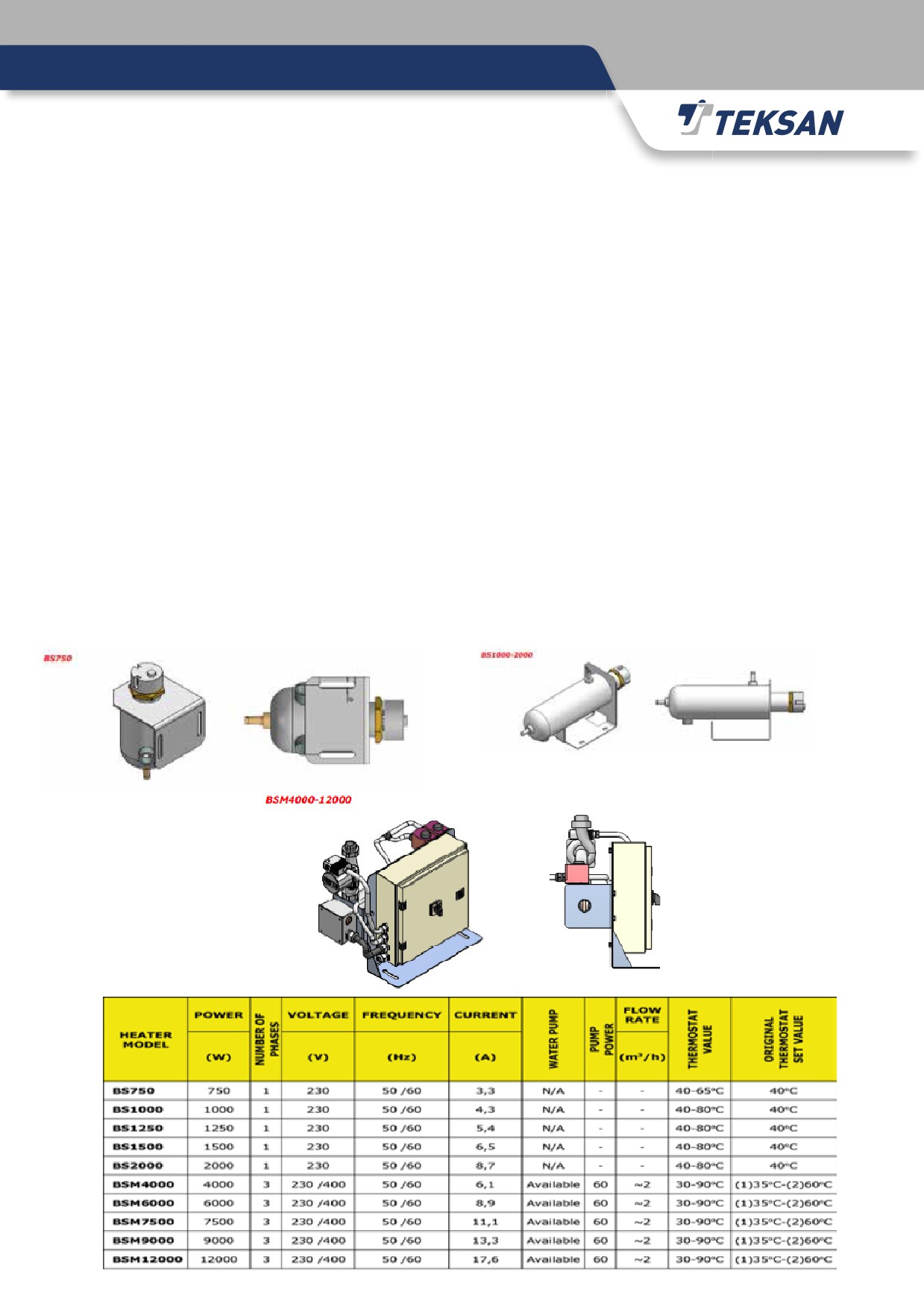
4.6.Engine Jacket Water Heaters
There can be used heaters on the engine’s cooling water circuit, in order to ease starting up and taking load
actions for the engine. These heaters are used as standard in automatic generator set applications, but it can also
be installed on manual systems optionally.
There are thermostats available installed on these heaters and they are set approximately up to 40°C.
Nominal power ratings of heaters may differ depending on the size of engine.
4.7.Transfer Panels
Transfer panels are used for controlling and transferring the output power safely. So the equipment in these panels
(circuit breaker, contactor, fuses, etc…) must be at proper ratings depending on the output power and current
rating of generator set. The switching equipment must be controlled by the generator set controller in automatic
mode applications.
The transfer panel must be designed so that the generator set cannot be started or stopped under load, otherwise
there may be seen various problems on both the generator set or the alternator.
Under voltage release coils must be used for motorized circuit breakers applications. Also changeover relays can
be used in manual mode applications with thermal magnetic circuit breakers.
Wiring diagrams of the transfer panels supplied, can be found inside the documentation supplied along with the
generator set.
5-MAINTENANCE
5.1.General
Maintaining the generator set properly and periodically is a key factor in terms of efficiency, durability and safety of
operation. It also necessary for being sure that the generator set is always ready for operation and minimizing any
risk of failure on the generator set.
The parts to be controlled or to be replaced during a maintenance activity, have been declared in the “Generator
Set Maintenance Schedule”. Any further details about this issue can also be looked up from the manuals supplied
with both the engine and alternator. Be sure to perform all maintenance activities according to the recommended
schedule.
All the documentation including service registration forms, model and serial number nameplates, drawings or
diagrams, spare part lists, maintenance schedules and the manuals supplied with the generator set, must be kept
in a good condition. Remind that all these documentation may be needed during any service or repairing activity.
The staff who will perform any maintenance or repair activity on the generator set, must be trained and authorized.
• Be sure that there is nobody left around or inside the generator set before running it or performing any
maintenance or repair activity on it. Keep all the doors locked after finishing any repair or maintenance activity.
• Be sure that the engine is stopped before performing any maintenance activities like lubrication oil fill-up,
coolant fill-up or changing battery electrolytes.
• Also remove the AC supply connection of the charger device and the battery (-) connection from the battery
pole before starting to work on the engine. This will prevent the engine from starting
without your control. Also place a warning around the connections you have removed, so
nobody around touches or re-connects them.
•
Always be sure to make the necessary changes on the generator set when it is
stopped. Stop it for making changes, make the necessary changes and run it again. Do not
forget that only some qualified technicians which have a deep expertise on related issues,
can make changes on a running generator set.
ATTENTION!
40
5.2.Maintenance of the Diesel Engine
Please see the detailed instructions in “Diesel Engine Operation and Maintenance Manual” supplied with the
diesel engine.
5.3.Maintenance of the Alternator
Any maintenance or repair activity to be performed on alternator, must be carried on by trained and qualified
technicians. Also be sure that the alternator is not running and all necessary precautions are taken before taking
action.
The maintenance intervals are specified depending on the alternator, operation mode and environmental conditions.
In general the alternator must be checked for any vibration, detonation, abnormal sound before commissioning and
one (1) year (or after 500 running hours) after it. Also the tightness of all electrical or mechanical connections and
any defections on the alternator body or the cooler fan must be checked during these maintenance activities.
Alternator bearings can be used up to 20.000 running hours under normal conditions, but some factors like improper
lubrication, very high ambient temperature or high levels of vibration will be decreasing this lifetime period.
The recommended check and change period for the lubricant (grease) is 4.000 hours. Some recommended lubricant
(grease) types are as follows; Mobilux 3 (MOBIL OIL), Alvania 3 (SHELL), GR MW 3 (AGIP), Beacon 3 (ESSO).
The temperature at the alternator bearings level must not exceed 60°C. In case of any doubt about corrosion on
bearings, the operating temperature must be measured and checked. Check the coupling, if the temperature is rising
up to 80°C during operation. If it is normal but the bearings change colour to blue, then the bearings must be replaced
with a new one. Any dismantled bearing must be replaced with a new and equivalent one, it is not recommended to
re-install and use any dismantled bearing. Heating the bearing up to 80°C will ease the assembling process.
Check the mechanical connection and the centring between the coupling of alternator and the flywheel of engine.
Make sure that all bolts on this connection are properly tightened. Sealants like “Loctite - Type 242” can be used on
this connection for providing extra strength.
Generally, alternators are manufactured with a single bearing. For this manner, the user must be very careful while
lifting or carrying it. Because the rotor can drop down if the alternator is lifted, so the rotor must be fixed before lifting.
It is strongly recommended to perform an insulation test on stator windings, if the alternator has not running for a long
time. Be sure to remove all the terminal connections on AVR before this insulation test. If the measured resistance
between the stator winding and the ground is lower than 5 Megaohms, then the alternator must be cleaned, dried
and maintained properly. Related industrial cleaners can be used for this cleaning purpose.
Wait for some time after applying cleaner on windings, then blow compressed air to remove
this volatile substance on it.
Please see the detailed instructions in “Alternator Operation and Maintenance Manual”
supplied with the alternator.
41

5.4.Lubrication Oil
The lubrication oil must be changed periodically in specified intervals for obtaining the best performance and
lifetime for engine. The lubricant and this changing period is specified by the engine manufacturer, so be sure
to comply with these standards, specifications and instructions about lubrication, otherwise the engine may be
damaged.
Use a reputable brand of lubricant in accordance with API standards.
The quality and specifications of the oil to be used may vary depending on environmental conditions, so be sure to
use a proper lubricant. In some cases, if the temperature is lower than a minimum level, the engine may lose its
cold start capability so it is not advised to run the engine for a long time in such conditions.
Any further details about the lubrication system, lubricant specifications and intervals for changing the lubricant,
can be found on the “User and Maintenance Manual” supplied with engine.
5.5.Co
Coolants are mixtures of water, antifreeze and any other chemicals for several purposes. The main purpose of using
this mixture is cooling the engine. But with addition of antifreeze and other chemicals, this mixture prevents the
cooling water from freezing and protects the cooling system against corrosion.
Use 50% antifreeze (glycol) and 50% pure water as coolant mixture if there is any risk of freezing. By using this
mixture throughout the whole year, the engine will be protected at temperatures down to -40°C.
For ensuring an effective protection against corrosion, it is recommended to use at least 40% antifreeze inside the
coolant mixture.
Even it can be possible to decrease the freezing point of the coolant inside the engine down to -56°C, it is not
recommended to decrease it further since it may cause a decrease on the cooling performance of the engine.
In order for more precise ratios, the mixture should be mixed in a separate tank before filling
into cooling system.
Any further details about the cooling system, coolant specifications and intervals for changing
the coolant, can be found on the “User and Maintenance Manual” supplied with engine.
Drinking this coolant mixture of water, antifreeze and some other chemicals, is dangerous.
42
5.6.Fuel
The fuel to be used on your generator set, should be complying with the standards and specifications below in
order for a reliable and environment friendly operation.
* EN590 * ASTM D975 NO 1-D, 2-D
* JIS K2204 TYPE 1,2,3 * ISO 8217 DMX-CLASS
* DIN 51601 DIESEL FUEL * BS 2869 CLASS-A1, A2
The temperature of the fuel to be used, should not be exceeding 40˚C.
NOTE: More details about the required fuel specification can be found in the Engine Operation and Maintenance
Manual.
Sulphur content of fuel must meet the legal norms in each country. If the Sulphur content exceeds 0.5%, then the
engine oil must be changed more frequently.
Fuel Sulphur Content
Oil Change Interval
(%)
<0,5
NORMAL
0,5 - 1,0
0,75
<1,0
0,5
5.7.Maintenance of Batteries
Different types of batteries can be used in generator sets. Maintenance free batteries are used in TEKSAN
products. They are completely enclosed and does not require any pure water addition.
Discharge duration is long for batteries on TEKSAN products, because their internal resistance is very low (5
milliohm).
Since the batteries are completely based on oxygen recombination principle, no waste gas is formed and there is
no gas release on these batteries. They are also equipped with special low-pressure safety valves for this same
reason.
Operating temperature range for these batteries is very wide (approximately between -20°C and 60°C).
Chemical energy is converted to electric energy in batteries, so there are several chemical reactions in battery
cells. Since these chemical reactions are reversible, the batteries can be charged and discharged many times.
These batteries can be used (charged/discharged) up to approximately 4 years, they must be replaced after then.
Another widely used battery type is lead acid type, which is formed of positive and negative electrodes immersed
into the electrolyte (sulphuric acid) inside cells between sheet plates.
43
Check the density of battery liquid with a hydrometer. The proper readings should be around 1,27 under nominal
conditions and temperature (15°C).
Pure or distilled water is used in electrolyte solution, so the water to be added into the battery must also be pure
water.
Keep the batteries clean for a better performance.
Clean the top cover of the battery before lifting it for any purpose. Add pure or distilled water up to a height 5-10
mm above plates, close and tighten the top cover. Dry the top cover and keep it clean and dry.
Check the operation range of batteries before installation, especially in terms of temperature (between -5°C and
50°C). Inappropriate selections will affect the operation, performance and lifetime of battery due to freezing or
boiling issues.
• Do not smoke or have any spark/flame around the batteries, they may be releasing
flammable gases.
• Handle batteries with care and wash your hands after touching them for protection
against acid burns.
• Wear protective clothes before changing or maintaining the batteries.
• Keep anyone unauthorized, away from the batteries and its charging system.
• Do not forget to check the charging system together with the batteries.
• Batteries should always be kept under a buffer charge. Batteries that are not
charged for a long time, may break.
ATTENTION
5.8.Maintenance of Radiator
The radiator installed on your generator set is designed and manufactured for functioning properly for long years, if
the necessary and recommended maintenance activities are performed properly and periodically.
Here are some recommendations about the operation and maintenance of your radiator;
• The coolant liquid inside the radiator is at high pressure and temperature, so be careful when opening the cap
or any draining points.
• Do not perform any repair or maintenance activity on the radiator until it is cooled down to a safe temperature.
• Do not perform any repair or maintenance activity on the radiator while the cooler fan is running or the any
protective covers on it are removed.
• Corrosion is the very first reason for many problems seen on radiators, be sure to check it in case of any
failure.
• Be sure that there is no leakage on the radiator, any inlet/return line or any hose connections.
• Radiators should be filled and kept completely full. This will prevent any failures due to corrosion. Partially filling
radiators may cause corrosion inside the radiator. For this same reason, all the liquid must be drained if the
radiator will not be running or will be stored for a long time.
• The water to be used in a radiator, must be pure, distilled or soft for preventing corrosion. Also additive
chemicals can be used in the coolant mixture for preventing corrosion.
• If the radiator is running at a dirty and dusty ambient, then its cells may be blocked with dust, dirt, steam
or different particles. This will affect the operation, performance and the lifetime of the radiator and cause
overheating issues.
44
• The radiator must be cleaned properly and periodically for the reason above. Low pressure steam should be
used for this cleaning purpose. The radiator can be immersed into an alkaline solution in case of any stronger
sediments. The radiator must be washed with hot water after waiting at least 20 minutes inside this solution.
5.9.Low Load Operation
Besides overloading, running a generator set under too light loading conditions can also be harmful for the
generator set. Running the generator set below a specified loading rate may cause damage on engine and reduce
its reliability. This fact must be taken into consideration, especially in higher capacity generator set applications.
Any generator set to be used in a standby application must be loaded not less than 30% of its full capacity.
Any generator set must not be running under no-load or low-load conditions for a long time. If you really have to run
it in such conditions, then the duration shall be minimized. For example; if the weekly test will be performed without
load, then it should not take more than 10 minutes.
Any engine which has operated under a 30% or less loading condition for 1 hour, must be operated with a 60% load
for 30 minutes in order for the engine to re-gain its performance.
For burning and cleaning any remaining carbon compounds inside the engine and exhaust system, any generator set
must be operated with a 75% load and for a 4 hours duration every year. The load level must be increased gradually.
If the sufficient loading rate cannot be provided for the generator set, then a dummy load can be connected to it.
Maintenance intervals must be more frequent for the generator sets running under low loading conditions. For
example the air filter must be replaced every year, the oil filters must be changed every 6 months if a generator set
is running in standby mode and under low loading conditions.
Here are some problems that may occur in case of running the generator set under low loading conditions;
Oil Leakage at Exhaust or Air Inlet Systems
• Since the temperature inside cylinders will be less than normal level, the fuel delivered to cylinders cannot be
combusted properly. Unburned fuel and oil steam become condensed in the exhaust system.
• Also the turbocharger oil seals cannot function properly due to this lower temperature, so the oil will be leaking
with air to the air inlet and exhaust systems.
• Due to these two reasons above, oil leakage problems can be seen on air inlet and exhaust manifolds and so
the oil consumption of the engine will be higher than normal.
This situation is faced especially on Standby(ESP) generator sets which are operated with no load during weekly
test running.
Carbon Accumulation on Cylinder Covers and Exhausts Manifolds
In case of operating the diesel engine under low load for a long time, the combustion process is performed under
low temperature. As a result of this low quality combustion, there may be oil steam and soot contaminated at
cylinder covers, valves, piston rings, exhaust manifold and injector nozzles. This all will lead up to a lower engine
performance and possibly a serious damage on the engine later.
45
Corrosive Damage
If the temperature of the engine body is not at a proper value, then the lubrication inside the engine will not be
done properly so this will cause more corrosion on moving components.
Deterioration Of Lubrication Oil
Due to loss of combustion performance, unburned fuel mixing with oil in the cylinder makes the oil deteriorated.
Spoiled oil causes early abrasion of the moving parts and bearings.
Abrasion will firstly affect the bearings of turbocharger operating at very high speed and this situation results in oil
leakage and damage.
By this operation, oil consumption in the engine dramatically raises.
White Smoke
If the fuel cannot be combusted in cylinders properly, then it can be thrown out from the exhaust line as a white smoke.
5.10.Long Term Storage
If the generator set will not be used or will be stored for a long time, some protective precautions must be taken
since this non-operating or storage duration will have negative effects on engine, alternator and other equipment.
Running the generator set directly without any controls after this long duration, may cause damage on all these
main parts.
There must be taken some additional precautions if the generator set will be stored for a duration more than 3
months. However if the storage duration is 3 months or less, then it will be enough to cover the generator set with
a protective packing material and store it in a dry and clean place. It also should be operated at least once in every
15 days.
In order not to face any problems on re-commissioning after this storage duration, the generator set must be
operated for a while (until it reaches to its nominal operating temperature; 75°C) and checked for any failures
before storage.
The procedures to be followed (by an authorized technician) before any long storage duration are as follows;
Storage Between 3 And 6 Months
• Change the engine oil and oil filters,
• Check the coolant level and rating in cooling system, re-fill or re-rate if necessary,
• Change the fuel filter. Drain the water or any residue from the fuel tank and fill with fuel up to maximum level.
• Test the generator set for a final time and stop it after the test is finished,
• Remove all battery connections, clean and remove the batteries. Be sure to keep the batteries under charge,
• Clean generator set completely with a damp cloth. Do not use pressurized water for cleaning purposes,
• Check all the electrical connections and apply moisture repellent spray on all electrical system and equipment,
• Apply protective (moisture repellent) spray/oil to electrical system and its components.
• Apply protective (moisture repellent) spray/oil to air intake canals.
• Loosen the V-belts,
• Close/block the air intake and exhaust outlet channels,
• Pack the generator set properly and place a warning label on it.
• Keep the packed generator set at a dry, clean place and ensure that it will not be directly exposed to harmful environmental
conditions like dust, wind, sun, rain, snow and sudden temperature changes.
46
Storage More Than 6 Months (Up To 2 Years)
• Drain the engine oil.
• Fill with diesel engine protective oil up to maximum level of the oil dipstick.
• Immerse the fuel intake and return canals to a pot which contains 1/3 protective oil (JIS K2246 NP9) and to a pot that contains 2/3
diesel oil mixture.
• Run the engine until it consumes 2 litres of this mixture and then stop.
• Drain the fuel system and connect the fuel intake and return canals to their normal location.
• Drain the fuel tank and clean.
• Drain the protective oil from the engine and filter.
• Spray protective oil to air intake manifold.
• Spray protective oil to compressor side of the turbocharger.
• Disassemble the cylinder head covers. Spray protective oil to valve, valve spring, valve guide, cylinder head and rocker arm, then
close the cylinder head cover again.
• Seal air inlet and exhaust outlet.
• Loosen the V-belts.
• Disconnect the battery cables. Clean the battery and leave it under charge continuously.
• Clean the generator completely with a wet cloth. Do not use pressurized water.
• Check the electrical connections and terminals.
• Spray the moisture repellent to electrical system and its components.
• Cover the entire generator and post a warning sign on it.
• Store the generator in a dry place where there is no temperature changes. Generator should be protected from sun light and rain.
Re-Commissioning After Storage
•
Remove the cover from the generator and remove sealing from air inlet and exhaust outlet.
•
Inspect all sections of the engine.
•
Pay attention that the installation made basis on the rules and the commissioning procedures are completed before running the
generator.
•
Refresh the engine oil and filter.
•
Clean the fuel tank and fill with new fuel.
•
Replace fuel filter.
•
Clean the air filter, if necessary replace it.
•
Control and tighten the V-belt and pulleys.
•
Disassemble the turbo lubricating pipe and lubricate the bearings. Then, rotate the turbo manually.
•
Control valve tip clearances, if necessary adjust them. (For storage more than 6 months)
•
Disassemble the cylinder head covers. Lubricate the valve, valve spring, valve guide, cylinder head and rocker arm, then close the
cylinder head covers again.
•
Check all the hoses and pipes, tighten clamps and screws.
•
If there is any disjointed screw or plug, assemble them.
•
Check the coolant level and ratio of anti-freeze. If it is drained before the storage, then fill it with a mixture of new 50% anti-freeze and
50% water.
•
If it is realized that there is moisture in the storage ambient, stator winding isolation test should be done before operating the
alternator. Before this process, AVR cable connections should be disconnected. If the measured value is less than 5 megaohm, then
alternator should be cleaned, dried and tested again.
•
Before the cranking, rotate the engine 2-3 cycles manually.
•
Check that batteries are fully charged.
•
Disconnect the fuel solenoid connection and rotate the engine for a short term via starter.
•
Run the generator under no load until it warms.
•
Check for excessive vibration, noise, oil-fuel-water leakage.
•
Run the generator set under load and test it again.
47

5.11. General Maintenance Schedule
Periodically (Engine Running Hours)
At Least
DIESEL GENERATOR SET
GENERAL MAINTENANCE SCHEDULE
ENGINE LUBRICATION SYSTEM
Check the Oil Level
Change Oil
Change Oil Filters
ENGINE COOLING SYSTEM
Check the water heater blocks
Check whole Cooling System for any Coolant Leakage
Check the Coolant Level
Check the Cleanliness of Radiator
Change the Coolant
AIR INLET AND EXHAUST SYSTEM
Check whole Air System for any Leakage (hoses, clamps, etc..)
Check the Turbocharger
Clean or Change Air Filters
Check whole Exhaust System for any Leakage (pipes, spiral, etc.)
Check the Colour of Exhaust Smoke
FUEL SYSTEM
Check the Fuel Level
Change the Fuel Filter
Check whole Fuel System for any Fuel Leakage
Drain the Water inside "Water Seperator Filter"
Clean the Fuel Tank
Check the Injector Nozzles
ELECTRICAL SYSTEM
Check all the Pressure, Temperature Sensors and Gauges
Check the Control Panel and Generator Set Controller Unit
MISCELLANOUS
Check the Tensions of V-belts
Check the Radiator Fan and its Blades
Check any Screws or Bolts used for Assembling Purposes
Check the Compression Pressure (if necessary)
Perform a General Cleaning on whole Generator Set
Check for any Strange Noise when the Engine is Running
Check and Clean the Oil Pan Breather Hose
48

6-TROUBLESHOOTING
6.1.General
• The following inspections and corrective actions should be performed by a well-trained and authorized staff, by
using appropriate equipment.
• Do not change any settings or replace any part without a full-knowledge on related issues.
• You can find any further details in the troubleshooting sections of “Operation and Maintenance Manuals”
supplied with the engine, alternator and any other equipment used on generator set.
• If you cannot get a solution by using the table below, feel free to contact TEKSAN or its authorized dealers any
time.
49
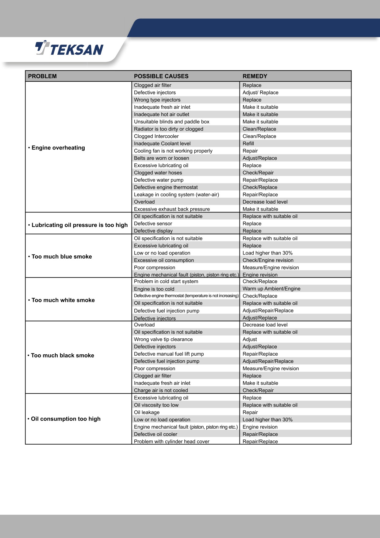
50

51
7-WARRANTY
Duration
This warranty applies to new Teksan Diesel Generator Sets to be free from defects in material and workmanship in
production for 24 months or 1.000 hours from the date of delivery to first user (which occurs first). Warranty period
is limited by 30 months from the date of shipment ex-works Teksan
Teksan Responsibilities
If a defect in material or workmanship is found during the warranty period (provided that Buyer/Owner has fulfilled
its due contractual obligations), Teksan Generator will, during normal working hours and through a place of
business of a Teksan Dealer or other source approved by Teksan:
• Replace or repair the defective parts, at Teksan’s discretion
• Provide for reasonable repair costs to correct the defect as agreed with Teksan
• Provide for the cost of oil and filters which are made unusable by the defect
Teksan either will dispatch parts to the Buyer/Owner free or to repair at the factory or on site. If the repair is
decided to perform at the factory by Teksan, the Buyer/Owner is responsible to disconnect the product from and
reconnect the product to its attached equipment, mounting and supporting systems as well as transporting the
product from the site to the factory and from factory to the site.
If the repair is decided to perform at site, travel expenses are not covered by Teksan.
Parts of complete products replaced will become the property of Teksan and they shall be forwarded to Teksan (if
requested), carriage-paid by Buyer/Owner.
Any parts repaired or replaced shall be under warranty, until the original warranty period for the diesel generator
set expires.
Buyer/Owner Responsibilities
• Buyer/Owner should install, operate and maintain the generator set in accordance with the maintenance and
operation, diesel engine and alternator handbooks supplied with the genset. If these books are lost, Buyer/
Owner is responsible to provide those books. In case of failures occurred due to not respecting to these books,
the warranty will be invalid.
• Commissioning approval and start-up process should be made by Teksan dealers or its authorized
representatives.
• Giving timely notice of a warrantable failure and making the equipment available for repair as the defect has
become apparent.
• Accepting the Teksan’s sole judgment as to whether the faulty is under warranty coverage or not.
• Any costs of investigations, unless a defect is accepted by Teksan as a warranty claim.
• Any costs in excess of the purchase price of the genset.
• Other miscellaneous costs such as courier, travel, mileage, lodging, taxes, telephone calls, overtime, etc.
• Buyer/Owner has the right of searching and asking for the ID card from the staff appointed for technical
service.
• Disconnecting/Reconnecting the product from/to its attached equipment, mounting and support systems as
well as to transport the product from the site to the factory and from factory to the site.
• Sufficient amount of lubricating oil, coolant or additives with specifications specified in the Maintenance and
Operation Handbook should be used. In case of using lubricating oil and coolant that lost property or dirty or
with different specifications and standards, warranty will be invalid.
52
• After Teksan’s transportation responsibility (as stated in contract) is finished, transportation, loading and
unloading is under Buyer/Owner’s responsibility. The possible damages during these processes are not under
the warranty coverage.
• The storage of the generator set during the time between the delivery or commissioning date and the first
start-up date of the generator set. If this duration is longer than 3 months, then storage must be done with
respect to storage principals as indicated in the Maintenance and Operation Handbook.
• Generator set control unit should be programmed, set or changed under Teksan approval.
• Run and stop the generator set stated as in the maintenance and operation handbook. Do not run or stop the
generator set under load. This may damage engine valves and its components, alternator exciter windings,
rotating diodes, suppressor and voltage regulator card.
• Commissioning approval is only valid for installation location. If the position of the generator set is desired to
be changed, Teksan dealer or authorized representatives should be informed.
• Original spare parts and consumable items (oil, fuel, filter, belt etc.) approved by Teksan should be used.
• Completing any outstanding payments for the purchase of equipment, parts or services relating to the
equipment under warranty.
Limitations
The warranty does not cover;
•
Periodical maintenance, controls and settings should be made strictly according to maintenance and operation
handbooks.
•
Any interference to generator set by people not confirmed by Teksan.
•
Any failures resulting from abuse, neglect and/or improper repair.
•
Any failures resulting from Buyer/Owner’s delay making the product available after being notified of a potential
product problem.
•
Normal wear, the spare parts that should be changed and consumable items such as lubricating oil, filters,
coolant, V-belt, injector nozzles etc.
•
Any failures in batteries or failures resulted from batteries.
•
Any failures resulted from using biodiesel, jet fuels (JP), sub-kerosene fuel, fuel-oil, benzene, etc. and
additionally dirty, water mixed, with chemical additives. Diesel fuel, specified in the handbooks should be used
for the diesel generator sets.
•
Any failures resulted from modifications and additions on Control panel systems - manual, automatic,
synchronization panels, transfer panels, equipments, etc. - These are should be made by Teksan or authorized
representatives.
•
Any failures of switching devices resulted from high current, low or high voltage due to the fact that generator
transfer panel is made suitable to generator output rating - contactor, motor circuit breaker - etc.
•
Any failures resulted from erasing, removing or changing of the labels belonging to Generator Set.
•
Any failures resulted from under no-load or low load as indicated in Maintenance and Operation handbook.
•
Any failures resulted from operating the generator set in different operation mode, loads greater than rated
power as stated on its label (Standby) and unbalanced load.
•
Any failures emerged after warranty period expiration date will not be considered under warranty coverage.
•
Any failures resulted from act of god, earthquake, snowstorm, avalanche, fire, flood or mains electricity are not
under warranty coverage.
•
In no event will Teksan be liable for loss of use, loss of profits, loss of or damage to other property,
inconvenience, commercial loss or other special, incidental or consequential damages whatsoever.
•
Any warranty of fitness for purpose shall not be effective unless explicitly confirmed by Teks an in writing. In
case of an express confirmation of fitness for purpose, the provisions above shall apply accordingly.
53

Claim Submissions
• Warranty service requests should be claimed to Teksan dealer or authorized representative who made
commissioning process.
• Buyer/Owner has to report failure without delay by “Warranty Claim Form” given in the documentation with
the delivery of generator set. This form has to be filled in right way completely. Especially, genset model,
serial numbers, engine running hours, description of the faulty, comments about the failure and defective parts
information should be supplied. Additionally, sufficient pictures of the failure should be sent.
• Any required operations in purpose of correcting the failure should be done after the approval of Teksan in
writing. Warranty claims must be done in 5 working days from date of failure.
• If requested, Buyer/Owner is responsible to present all kind of documents to prove the validity of the warranty
period.
DIESEL GENERATOR SET
GENSET MODEL
GENSET S.NO
ENGINE MODEL
ENGINE S.NO
ALTERNATOR MODEL
ALTERNATOR S.NO
DEALER’S
NAME
ADDRESS
TOWN
COUNTRY
TELEPHONE
FAX
INVOICE NUMBER
DATE AND STAMP
INVOICE DATE
OWNER’S
NAME
TEKSAN JENERATÖR ELEKTRİK SANAYİ VE TİCARET A.Ş.
ADDRESS
YENİDOĞAN MAH. EDEBALİ CAD. NO:12 34791 SANCAKTEPE
TOWN
ISTANBUL
COUNTRY
TURKEY
TELEPHONE
+90 216 312 05 50
FAX
+90 216 312 69 09
E-MAIL
info@teksan.com
DELIVERY PLACE
DATE AND STAMP
DELIVERY DATE
54