CESSNA C-172. Flight Operations Manual (2011)
NOVA AVIATION
Introduc)on
Flight
Operations
Sec)on,2
Limita&ons
Manual
Sec)on,3
C-172
Standard-Opera&ng-Procedures
Sec)on,4
Maneuvers
Sec)on,5,
Emergency-and-Abnormal-Procedures
Sec)on,6,
Performance
Sec)on,7,
Supplementary-Informa&on
Sec)on,8,
Appendix-A-&-B
October 23, 2011
NOVA AVIATION
Flight Operations Manual
Cessna 172s
NOVA
AVIATION
Procedures in this publication are derived from procedures in the FAA approved Airplane
Flight Manual (AFM) released in 2007. NOVA Aviation has attempted to ensure that the
data contained agrees with the data in the AFM. If there is any disagreement, the Air-
plane Flight Manual is the Final Authority.
October 23, 2011
-1-
How to use this Book
This book should be used as a supplement for the planning and
execution of all flights in a NOVA C-172s aircraft. Although an ex-
cellent resource, this information will not guarantee a safe flight.
Minimizing flight risk requires sound judgment and sensible operat-
ing practices. Safety of flight ultimately depends upon the deci-
sions made by you, the pilot.
Safe flights should be conducted in accordance with regulations,
ATC clearances, personal capabilities, and the aircraft operating
limitations described in the FAA Approved Airplane Flight Manual
and Pilots Operating Handbook (POH). Procedures in this publica-
tion are derived from procedures in the FAA Approved Airplane
Flight Manual (AFM). NOVA has attempted to ensure that the data
contained here agrees with the data in the AFM. If there is any dis-
agreement, the Airplane Fight Manual is the final authority. For
operations outside the United States, refer to the appropriate regu-
lations for that country. This publication should be in the pilot’s
possession during all flight operations.
-2-
Table of Contents
Before Takeoff - 35
Procedure (Do-List)
Section 1 - Introduction…………………………………………..8
Take-Off - 38
General - 8
Sample Take-Off Briefing
Single Pilot Resource Management - 8
Procedure (Flow Pattern)
Checklist Philosophy - 9
En Route Climb - 40
Classification of Checklists - 10
Procedure (Flow Pattern)
Reference Materials - 11
Cruise - 41
Terms and Abbreviations - 11
Procedure (Flow Pattern)
Contact Information - 12
Descent - 42
Section 2 - Limitations………………………………………….14
Procedure (Flow Pattern)
General - 14
Before Landing / Traffic Pattern - 44
V Speeds - 15
Procedure (Flow Pattern)
Performance Specifications - 16
Approach - 46
Stabilized Approach Criteria - 47
Section 3 - Standard Operating Procedures…………
18
VFR Criteria
General - 18
IFR Criteria
Checklist Completion for Normal Procedures - 19
Preflight - 20
Procedures - 49
Approach Briefing
Documentation
Equipment
Precision Approach
Non-Precision
Procedure (Flow Pattern)
Before Engine Start - 28
GPS Approach
Missed Approach
Passenger Briefing
Procedure (Do-List)
Go-Around - 54
Procedure (Memory)
Engine Start - 29
Procedure (Do-List)
Landing - 55
Normal Landing
Before Taxi - 33
Avionics Configuration
Short Field Landing
Soft Field Landing
Taxi-Out - 34
Procedure (Flow Pattern)
Cross Wind Landing
-3-
-4-
After Landing - 57
Section 7 - Supplementary Information……………………..74
Procedure (Flow Pattern)
General - 74
Arrival / Shut Down - 57
Pilot Qualification and Training - 74
Procedure (Flow Pattern)
Training
Section 4 - Maneuvers…………………………………………...60
Medical Certificates
General - 60
Pilot Duty Considerations - 75
Steep Turns - 60
Duty Time and Rest
Execution
Physiological
Maneuvering During Slow Flight - 60
Aircraft Maintenance - 76
Execution
Grounding of Aircraft
Recovery
Flight Planning - 76
Power-Off Stalls - 61
Weather - 77
Execution
Overview
Recovery
Hazards to Flight
Power-On Stalls - 62
Current Observations
Execution
Forecast Weather
Recovery
NOTAMS
Autopilot Stall Recognition - 63
Thunderstorm Flying
AP Stall Recognition (Power Off)
Temperature Minimums
AP Stall Recognition (Power On)
Operations in Icing Conditions
Section 5 - Emergency and Abnormal Procedures………….66
In-Flight Considerations - 81
General - 66
Turns after Takeoff
Checklist Completion for Abnormal Procedures
Weather Status
Checklist Completion for Emergency Procedures
Aircraft System Status
Pilot Status
Section 6 - Performance………………………………………….68
Situational Awareness
General - 68
Supplemental Oxygen
Time & Distance Chart - 69
Flight Safety - 83
Example of Computed Performance Data - 70
Sterile Cabin
Time, Fuel & Distance to Climb - 71
Smoking
Range Profile - 72
Incident and Accident Procedures - 84
Endurance Profile - 73
Emergency Landing
-6-
-5-
Aircraft Incident and Accident Notification
NTSB Field Office
Appendix A -Ground Reference Maneuvers………………….86
Turns Around-A-Point - 86
S-Turns - 87
Rectangle Course - 88
Appendix B - Commercial Maneuvers………………………..90
Eights on Pylons - 90
Chandelles - 92
Lazy Eight’s - 94
Appendix C - IFR Maneuvers………………………...…….…96
BAI Circuits - 96
Circuit A
Circuit B
Circuit C
Circuit D
Circuit E
Circuit F, G & H
Circuit I
Circuit J
Circuit K
Circuit L
ILS Circuit
Unusual Attitude Recoveries - 106
-7-
!
Section 1
Introduction
1. Maintain Aircraft Control
Section 1 - Introduction
The number one priority of the pilot is to maintain aircraft
General
control. Pilots should maintain a high level of
vigilance dur-
ing periods of high and low workload to ensure aircraft con-
Procedures in this publication are derived from procedures in the FAA
trol is always maintained.
Approved Airplane Flight Manual (AFM). NOVA Aviation has at-
tempted to ensure that the data contained agrees with the data in the
2. Navigation
AFM. If there is any disagreement, the Airplane Flight Manual is
Once aircraft control is assured, pilots should set and ver-
the final authority.
ify the avionics are correctly configured for navigation.
This task includes programming GPS units and the PFD.
Single Pilot Resource Management
Use of the autopilot may assist with accomplishing these
Single pilot resource management (SRM) is the art and science of
tasks. Pilots should closely monitor flight parameters
while programming various avionics equipment.
managing all the resources available to a single-pilot to ensure that
the successful outcome of the flight is never in doubt.
3. Communication
Communication is an important task in the aircraft but fol-
The majority of Cessna aircraft operations are conducted single-pilot.
lows aircraft control and navigation as a priority. Communi-
The work load associated with flying the aircraft, configuring and
cate intentions and relay instructions clearly to ATC/CTAF
monitoring avionics, communicating with air traffic control, and deci-
while maintaining aircraft control.
sion making can be overwhelming at times. The following SRM pro-
cedures have been adapted from cockpit procedures common to
∙Note∙
dual pilot transport category aircraft.
Using Standard Operating Procedures will aid the pilot in timely com-
pletion of required tasks and allow the pilot to maintain high levels of
General aviation pilots have a great deal of latitude on how to man-
situational awareness.
age and operate aircraft. To ensure the highest levels of safety it is
strongly recommended that these single-pilot operating procedures
Checklist Philosophy
be incorporated into the operation of the aircraft.
When used properly, checklists enhance safety of flight by confirming
Priority of Tasks
the aircraft is appropriately configured for the flight condition. At the
same time, checklists expedite the completion of procedures that are
The following is a list of priorities that apply to any situation encoun-
necessary to transition to subsequent phases of flight.
tered in flight. Pilots must adhere to these priorities during every
flight.
The electronic checklist in the MFD should be used anytime the MFD
is running. Use of electronic checklists will help keep the cockpit or-
ganized and functional. Use a paper checklist whenever the MFD
electronic checklists are not available.
-8-
-9-
Classification of Checklists
All checklist procedures can be assigned one of three classifications:
Normal:
Procedures used during normal operations. Normal
checklists can be found in the Normal Procedures
section of the POH.
Abnormal:
Procedures used in response to system malfunctions
that, while not immediately threatening, may affect
safety of flight if not addressed. Abnormal checklists
can be found in the Abnormal Procedures section of
the POH.
Emergency:
Procedures used in response to system failures and
malfunctions that are an immediate threat to safety of
flight. Emergencies require immediate action by the
flight crew to ensure a safe outcome. Emergency
checklists can be found in the Emergency Proce-
dures section of the POH.
-10-
Reference Materials
The following references supplement the content of this publication:
• Federal Aviation Regulations (FARs) or governing regulations,
as applicable
• Aeronautical Information Manual (AIM)
• FAA Approved Airplane Flight Manual and Pilot’s
Operating Handbook
• Advisory Circulars
• Avionics Pilot Guides and Manuals
Terms and Abbreviations
The following terms and abbreviations will be referenced in this manual.
AP
Autopilot
ATC
Air Traffic Control
DA
Decision Altitude
ETA
Estimated Time of Arrival
ETE
Estimated Time En-route
FAA
Federal Aviation Administration
FAF
Final Approach Fix
FITS
FAA Industry Training Standards
GNS
Global Navigation System
GPS
Global Positioning System
GS
Glide Slope
IAF
Initial Approach Fix
IAP
Instrument Approach Procedures
LNAV
Lateral Navigation
LPV
Localizer Performance with Vertical Guidance
MAP
Missed Approach Point
MDA
Minimum Descent Altitude
MFD
Multi Function Display
NAS
National Airspace System
PFD
Primary Flight Display
PIC
Pilot-In-Command
SRM
Single-Pilot Resource Management
VNAV
Vertical Navigation
VTF
Vectors-To-Final
WAAS
Wide Area Augmentation System
-11-
Contact Information
NOVA Flight Desk…………………………877-FLY-NOVA (877-359-6682)
Contact Information
After Hours:
Angel Cortes…………………….…...973-769-0557
BLANK PAGE
-12-
-13-
!
Section 2
Limitations
Section 2 - Limitations
General
The Limitations Section of the Pilot’s Operating Handbook (POH) is the offi-
cial document approved by the Federal Aviation Administration. It provides
operating limitations, instrument markings, basic placards required by regu-
lation, and standard systems and equipment required for safe operation.
For amended operating limitations for airplanes equipped with optional
equipment, refer to Section 9 - Supplements of the Pilot’s Operating Hand-
book.
Compliance with the operating limitations in the Pilot’s Operating Hand-
book is required by Federal Aviation Regulations.
-14-

-15-
Performance
Specifications
BLANK PAGE
-16-
-17-
!
Section 3
Standing
Operating
Procedures
Section 3 - Standard Operating Procedures
General
The Standard Operating Procedures section describes the recommended
procedures when operating a NOVA Cessna 172s NAV III during visual an
instrument conditions. This information should serve as a framework for air-
craft and avionics management. The procedures outlined are considered
the best operating practices while flying a NOVA Cessna 172s NAV III; how-
ever, these procedures may not be inclusive to all variables encountered in
the national airspace system. NOVA pilots are encouraged to follow the
procedures outlined in the manual and use their best judgment when han-
dling non standard situations.
Utilizing these standard operating procedures will enhance the situational
awareness of the pilot in both single pilot and crew situations and allow for
timely completion of tasks in the aircraft. Adhering to these procedures will
help the pilot take full advantage of the aircraft’s capabilities while maintain-
ing a high level of safety.
∙Note∙
Procedures in this publication are derived from procedures in the FAA Ap-
proved Airplane Flight Manual (AFM). NOVA has attempted to ensure that
the data contained agrees with the data in the AFM. If there is any disagree-
ment, the Airplane Flight Manual is the final authority.
-18-
Checklist Completion for Normal Procedures
Normal procedure checklists can be completed as a flow pattern or a
do-list. The appropriate method for checklist completion for each
normal procedure is indicated in the procedures section for each
phase of flight.
Do-List:
A do-list checklist is executed by reading the check-
list item and selecting the appropriate condition of
the item. Do-lists are used when procedure se-
quence and/or item condition is critical to completion
of the procedure and when ample time exists for com-
pletion of the checklist.
Flow Pattern:
The term “flow pattern” refers to a logical path
through the cockpit that the pilot will move along dur-
ing the execution of the checklist. Flow patterns pro-
vide us with a “do and verify” approach to checklist
completion. The items and their conditions are
memorized and executed without immediate refer-
ence to the written checklist. Following completion
of the flow pattern, the checklist is referenced as
soon as time and workload permit to ensure proce-
dure completion.
When used properly, flow patterns allow timely
configuration of the aircraft for the appropriate flight
condition. Flow patterns are used when procedure
sequence and aircraft condition is not critical and
there is an operational advantage to executing the
checklist items in a timely manner.
-19-
Preflight
The preflight inspection should be completed as a flow pattern when
the pilot is familiar with the aircraft preflight inspection checklist. Al-
ways refer to the aircraft checklist after the flow to verify all items
have been completed.
Documentation
The following documents must be in the aircraft for the flight:
• Airworthiness Certificate
• Registration
• Radio station license for international operations only
• Operating Handbook
• Weight and Balance
∙Note∙
Ensure that you have all current publications for avionics and other
systems accessible in flight for reference.
Equipment
The following equipment should be carried in the aircraft when appro-
priate:
• Survival kit (appropriate to the climate and conditions)
• Approved flotation devices for flights outside glide
distance to land
• Supplemental oxygen system for high altitude operations
• Chocks, tie downs, extra oil, tow bar, engine and airplane
covers
-20-
Procedure (Flow Pattern)
1. Cabin
a.
Pitot Tube Cover - Removed (check for pitot blockage)
b.
Pilot’s Operating Handbook - Accessible to Pilot
c.
Garmin G1000 cockpit reference guide - Accessible to
pilot
d.
Airplane Weight and Balance - Checked
e.
Parking Brake - Set
f.
Control Wheel Lock - Removed
∙Warning∙
When the master switch is on, using an external power source, or
manually rotating the propeller, treat the propeller as if the magnetos
switch where on. Do not stand, nor allow anyone else to stand within
the arc of the propeller since a loose or broken wire, or a component
malfunction, could cause the engine to start.
(Figure 3-1)
g.
Magnetos Switch - Off
∙Note∙
h.
Avionics Switch (BUS 1 and BUS 2) - Off
Visually check airplane for general condition during walk-around in-
spection. Airplane should be parked in a normal ground attitude to
i.
Master Switch (ALT and BAT) - On
make sure that fuel drain valves allow for accurate sampling. Use of
j.
Primary Flight Display (PFD) - Check (Verify PFD is On)
the refueling steps and assist handles will simplify access to upper
k.
Fuel Quantity (L and R) - Check
wing surfaces for visual checks and refueling operations. In cold
weather, remove even small accumulations of frost, ice or snow from
l.
Low Fuel L and Low Fuel R Annunciators - Check (Verify
wing, tail and control surfaces. Also, make sure that control surfaces
annunciations are not shown on PFD)
contain no internal accumulations of ice or debris. Prior to flight,
m.
Oil Pressure Annunciator - Check (Verify annunciator is
check that pitot heater is warm to the touch within 30 seconds with
shown)
battery and pitot heat switches on. If a night flight is planned, check
n.
Low Vacuum Annunciator - Check (Verify annunciator is
operation of all lights, and make sure a flashlight is available.
shown)
o.
Avionics Switch (BUS 1) - On
p.
Forward Avionics Fan - Check (verify fan is heard)
-21-
-22-
q.
Avionics Switch (BUS 1) - Off
4. Right Wing
r.
Avionics Switch (BUS 2) - On
a.
Wing Tiedown - Disconnect
s.
Aft Avionics Fan - Check (verify fan is heard)
b.
Main Wheel Tire - Check (proper inflation and general
t.
Avionics Switch (BUS 2) - Off
condition (weather checks, tread depth and wear, etc.))
u.
Pitot Heat Switch - On (carefully check that pitot tube is
c.
Fuel Tank Sump Quick Drain Valves - Drain
warm to the touch within 30 seconds)
Drain at least a capful of fuel (using sampler cup) from
v.
Pitot Heat Switch - Off
each sump location to check water, sediment, and roper
w.
Low Volts Annunciator - Check (verify annunciator is
fuel grade before each flight and after each refueling. If wa-
shown)
ter is observed, take further samples until clear and then
x.
Flaps - Extend
gently rock wings and lower tail to the ground to move any
y.
Master Switch (ALT and BAT) - Off
additional contaminants to the sampling points. Take re-
z.
Elevator Trim Control - Takeoff Position
peated samples from all fuel drain points until all contami-
nation has been removed. If contaminants are still pre-
aa.
Fuel Selector Valve - Both
sent, refer to warning below and do not fly the plane.
bb.
Alternate Static Air Valve - Off (push full in)
∙Note∙
cc.
Fire Extinguisher - Check (Verify gage pointer in green arc)
Collect all sampled fuel in a safe container. Dispose of sampled fuel
2. Empennage
so that it does not cause a nuisance, hazard or damage to the
environment.
a.
Baggage Compartment Door - Check (Lock with Key)
b.
Rudder Gust Lock (if installed) - Remove
∙WARNING∙
c.
Tail Tiedown - Disconnect
If, After repeated sampling, evidence of contamination still exists, the
d.
Control Surfaces - Check (freedom of movement and
airplane should not be flown. Tanks should be drained and system
security)
purged by qualified maintenance personnel. All evidence of contami-
e.
Elevator Trim Tab - Check (security)
nation must be removed before further flight.
f.
Antennas - Check (security of attachment and general
condition)
d.
Fuel Quantity - Check Visually (for desired level)
3. Right Wing Trailing Edge
e.
Fuel Filler Cap - Secure and Vent Clear
a.
Flap - Check (security and condition)
b.
Aileron - Check (freedom of movement and security)
-24-
-23-
5. Nose
Do not operate with less than 5 quarts. Fill to 8 quarts
for extended flight.
a.
Fuel Strainer Quick Drain Valve (located on bottom of
fuselage) - Drain
c.
Engine Cooling Air Inlets - Check (clear of obstructions)
d.
Propeller and Spinner - Check (for nicks and security)
Drain at least a cupful of fuel (using sampler cup) from
valve to check for water, sediment and proper fuel grade
e.
Air Filter - Check (for restrictions by dust or other foreign
before each flight and after refueling. If water is observed,
matter)
take further samples until clear and then gently rock wings
f.
Nose Wheel Strut and Tire - Check (proper inflation of
and lower tail to the ground to move any additional con-
strut and general condition of tire (weather checks, tread
taminants to the sampling points. Take repeated samples
depth and wear, etc.))
from all fuel drain points, including the fuel reservoir and
g.
Static Source Opening (left side of fuselage) - Check
fuel selector, until all contamination has been removed. If
(verify opening is clear)
contaminates are still present, refer to warning below and
do not fly the airplane.
6. Left Wing Leading Edge
a.
Fuel Tank Vent Opening - Check (blockage)
∙Note∙
b.
Stall Warning Opening - Check (Blockage)
Collect all sampled fuel in a safe container. Dispose of sampled fuel
so that it does not cause a nuisance, hazard or damage to the envi-
∙Note∙
ronment.
To check the system, place a clean handkerchief over the vent open-
ing and apply suction; a sound from the warning horn will confirm sys-
∙WARNING∙
tem operation.
If, After repeated sampling, evidence of contamination still exists, the
c.
Landing/Taxi Lights - Check (condition and cleanliness of
airplane should not be flown. Tanks should be drained and system
cover)
purged by qualified maintenance personnel. All evidence of contami-
7. Left Wing
nation must be removed before further flight.
a.
Wing Tiedown - Disconnect
b.
Engine Oil Dipstick / Filler Cap
b.
Fuel Quantity - Check Visually (for desired level)
1.
Oil Level - Check
c.
Fuel Filler Cap - Secure and Vent Clear
2.
Dipstick / Filler Cap - Secure
d.
Fuel Tank Sump Quick Drain Valves - Drain
-25-
-26-
∙Note∙
Drain at least a capful of fuel (using sampler cup) from each sump lo-
cation to check water, sediment, and roper fuel grade before each
flight and after each refueling. If water is observed, take further sam-
ples until clear and then gently rock wings and lower tail to the
ground to move any additional contaminants to the sampling points.
Take repeated samples from all fuel drain points until all contamina-
tion has been removed. If contaminants are still present, refer to
warning below and do not fly the plane.
IMPORTANT: Collect all sampled fuel in a safe container. Dispose of
sampled fuel so that it does not cause a nuisance, hazard or damage
to the environment.
∙WARNING∙
If, After repeated sampling, evidence of contamination still exists, the
airplane should not be flown. Tanks should be drained and system
purged by qualified maintenance personnel. All evidence of contami-
nation must be removed before further flight.
e.
Main Wheel Tire - Check (proper inflation and general
condition (weather checks, tread depth and wear, etc.))
8. Left Wing Trailing Edge
a.
Aileron - Check (freedom of movement and security)
b.
Flap - Check (security and condition)
-27-
Before Starting Engine
Complete the before starting engine checklist as a Do-List to start
the aircraft engine. Before starting the engine verify all preflight items
are complete and emergency equipment s on board and stored in the
proper location. Ensure seats are locked into position by verifying
the control handle is in the full down position.
During engine start, the aircraft should be positioned so that the pro-
peller blast is not directed toward any aircraft, hangar or person.
Passenger Flight Briefing
The pilot should provide a safety briefing, referencing the passenger
briefing card, to all occupants prior to each flight. The pilot should
also discuss sterile cabin procedures and other information as neces-
sary. At a minimum, passengers should be briefed on the following
items:
• Smoking
• Seatbelts
• Doors
• Emergency Exits
• Use of Oxygen
• Emergency equipment
Before Starting Engine (Do-List)
a.
Preflight Inspection - Complete
b.
Passenger Briefing - Complete
c.
Seats and Seat Belts - Adjust and Lock (verify inertia
locking reel)
d.
Brakes - Test and Set
e.
Circuit Breakers - Check In
f.
Electrical Equipment - Off
g.
Avionics Switch (BUS 1 and BUS 2) - Off
∙Caution∙
The avionics switch (BUS 1 and BUS 2) must be off during engine
start to prevent possible damage to avionics.
h.
Fuel Selector Valve - Both
i.
Fuel Shutoff Valve - On (push full in)
-28-
Engine Start
i.
Propeller Area - Clear (verify that all people and equipment
are at a safe distance from the propeller)
The engine start checklist should be accomplished as a Do-list. Se-
lect the proper engine start procedure based on outside air tempera-
j.
Master Switch (ALT and BAT) - On
ture and internal engine temperature.
k.
Beacon Light Switch - On
If engine has been exposed to temperatures at or below 20⁰F (7⁰C)
for a period of two hours or more, the use of an external pre-heater
∙Note∙
and external power is recommended. Failure to properly pre-heat a
If engine is warm, omit priming procedure steps l thru n below.
cold soaked engine may result in congealing within the engine and oil
hoses with subsequent loss of oil flow, possibly internal damage to
l.
Fuel Pump Switch - On
the engine and subsequent engine failure.
m.
Mixture Control - Set to Full Rich (full forward) until stable
If the engine does not start during the first few attempts, or if the en-
fuel flow is indicated (approximately 3-5 seconds), then set
gine firing diminishes in strength, the spark plugs have probably
to Idle Cutoff (full aft) position.
frosted over. Pre-heat must be used before another start is at-
n.
Fuel Pump Switch - Off
tempted.
o.
Magnetos Switch - Start (release when engine starts)
Starting Engine (With Battery) (Do-List)
p.
Mixture Control - Advance Smoothly to Rich (when engine
starts)
a.
Throttle Control - Open ¼ inch
∙Note∙
b.
Mixture Control - Idle Cutoff (pull full out)
If the engine is primed too much (flooded), place the mixture control
c.
Standby Battery Switch:
to idle cutoff position, open the throttle control ½ to full, and engage
the starter motor (start). When the engine starts, advance the mixture
1.
Test - (hold for 20 seconds, verify that green test
control to full rich position and retard the throttle control promptly.
lamp does not go out)
q.
Oil Pressure - Check (verify that oil pressure increases into
2.
Arm - (verify that PFD comes on)
the green band range in 30-60 seconds)
d.
Engine Indicating System - Check Parameters (verify no
r.
AMPS (M BATT and BATT S) - Check (verify charge shown
red X’s through engine page indicator’s)
(positive))
e.
BUS E Volts - Check (verify 24 volts minimum show)
s.
Low Volts Annunciation - Check (verify annunciation is not
f.
M BUS Volts - Check (verify 1.5 volts or less shown)
shown)
g.
BATT S Amps - Check (verify annunciator is shown)
t.
NAV Light Switch - On as required
h.
Standby Battery Annunciator - Check (verify annunciator
u.
Avionics Switch (BUS 1 and BUS 2) - On
is shown)
v.
Flaps - Retract
-29-
-30-
r.
Fuel Pump Switch - Off
Starting Engine (With External Power) (Do-List)
s.
Magnetos Switch - Start (release when engine starts)
a.
Throttle Control - Open ¼ inch
t.
Mixture Control - Advance Smoothly to Rich (when engine
b.
Mixture Control - Idle Cutoff (pull full out)
starts)
c.
Standby Battery Switch:
∙Note∙
1.
Test - (hold for 20 seconds, verify that green test
If the engine is primed to much (flooded), place the mixture control to
lamp does not go out)
idle cutoff position, open the throttle control ½ to full, and engage the
starter motor (start). When the engine starts, advance the mixture
2.
Arm - (verify that PFD comes on)
control to full rich position and retard the throttle control promptly.
u.
Oil Pressure - Check (verify that oil pressure increases into
d.
Engine Indicating System - Check Parameters (verify no
the green band range in 30-60 seconds)
red X’s through engine page indicator’s)
v.
Power - Reduce to Idle
e.
BUS E Volts - Check (verify 24 volts minimum show)
w.
External Power - Disconnect from ground power (latch
f.
M BUS Volts - Check (verify 1.5 volts or less shown)
external power receptacle door)
g.
BATT S Amps - Check (verify annunciator is shown)
x.
Power - Increase (to approximately 1500 RPM for several
minutes to charge battery)
h.
Standby Battery Annunciator - Check (verify annunciator
is shown)
y.
AMPS (M BATT and BATT S) - Check (verify charge shown
(positive))
i.
Avionics Switch (BUS 1 and BUS 2) - Off
z.
Low Volts Annunciator - Check (verify annunciator is not
shown)
j.
Master Switch (ALT and BAT) - Off
aa.
Internal Power - Check
k.
Propeller Area - Clear (verify that all people and equipment
are at a safe
1.
Master Switch (ALT) - Off
distance from the propeller)
2.
Taxi and Land Light Switches - On
l.
External Power - Connect (to ground power receptacle)
3.
Throttle Control - Reduce to Idle
m.
Master Switch (ALT and BAT) - On
4.
Master Switch (ALT and BATT) - On
5.
Throttle Control - Increase (to approximately 1500
n.
Beacon Light Switch - On
RPM)
o.
M BUS Volts - Check (verify that approximately 28 volts is
6.
M BATT Ammeter - Check (verify battery charging,
shown)
amps positive)
∙Note∙
7.
Low Volts Annunciator - Check (verify annunciator is
not shown)
If engine is warm, omit priming procedure steps p. thru r. below.
∙Warning∙
p.
Fuel Pump Switch - On
If M BATT ammeter does not show positive charge (+amps), or low
q.
Mixture Control - Set to Full Rich (full forward) until stable
volts annunciator does not go off, remove the battery from the air-
fuel flow is indicated (approximately 3-5 seconds), then set
plane and service or replace the battery before flight.
to Idle Cutoff (full aft) position.
bb. NAV Light Switch - On as required
cc. Avionics Switch (BUS 1 and BUS 2) - On
dd. Flaps - Retract
-31-
-32-
Before Taxi
It is recommended to set up the required navigation equipment and
communication frequencies for
the intended flight at this time. Set
primary airborne frequencies in COM 1 (ie. Tower, approach, depar-
ture, or center) and necessary ground frequencies in COM 2 (ie.
Ground, clearance, ATIS, FSS, or the FBO). Always lean mixture as
outlined below during all ground operations. This helps to prevent
the spark plugs from fouling.
Ground Leaning Procedure
a.
Set throttle to 1200 RPM.
b.
Lean the mixture for maximum RPM
c.
Set the throttle control to an RPM appropriate for ground
operations (800 to 1000 RPM recommended)
-33-
Taxi Out
∙Warning∙
A cause of brake failure is the creation of excessive heat through improper
Maximum continuous engine speed for taxiing is 1000 RPM on flat,
braking practices. Riding
the brakes while taxiing causes a continuous
smooth, hard surfaces. Power settings slightly above 1000 RPM are
build up of energy which may lead to excessive heat. Excessive heat
permissible to start motion, for turf, soft surfaces and on inclines.
causes warped brake rotors, damaged or glazed linings, damaged o-rings,
Use minimum power to maintain taxi speed.
and vaporized brake fluid. To avoid brake failure, observe the following
operating and maintenance practices:
Taxi-Out Procedure (Flow Pattern)
•
Directional control should be maintained with nose wheel steering
and rudder deflection supplemented with brake pressure as required
a.
Taxi Clearance - Obtain (for controlled airports, uncon-
trolled announce intentions)
•
Use only as much power (throttle) as is necessary to achieve forward
movement. 1000 RPM is enough to maintain forward movement un-
b.
Parking Break - Disengage
der normal conditions
c.
Brakes - Check (upon initial movement verify both brakes
•
Avoid unnecessary high speed taxiing. High speed taxiing will result
are functioning by applying pressure)
in excessive demands on the brakes, increased brake wear and the
possibility of brake failure.
d.
HSI Orientation - Ensure alignment with magnetic com-
pass
•
Use the minimum necessary brake application to achieve directional
control
e.
Attitude Gyro - Verify no Red X’s
•
Do not ride the brakes. Pilots should consciously remove pressure
f.
Turn Coordinator - Check (verify turn indicator and
from the brakes while taxiing. Failure to do so results in excessive
inclinometer are working properly, Turn indicator moves in
eat, premature brake wear and increased possibility of brake failure.
same direction of turns, inclinometer moves opposite direc-
tion of turn)
•
Refer to the handling, service and maintenance section of the POH
or the maintenance manual for recommended maintenance and in-
spection intervals for brakes
•
Wind deflection w/controls
Maintain high levels of situational awareness during all movements on the
airport surface to avoid runway incursions or accidents. Minimize tasks
such as reading checklists or folding maps while taxiing. Utilize the Safe
Taxi airport diagram to aid in situational awareness.
-34-
Before Takeoff
∙Warning∙
Complete the before takeoff checklist as a Do-List. Complete the
Maximum continuous engine speed for taxiing is 1000 RPM on flat,
checklist prior to taking the active runway or an appropriate run up
smooth, hard surfaces. Power settings slightly above 1000 RPM are
area prior to departure. The before takeoff checklist will ensure the
permissible to start motion, for turf, soft surfaces and on inclines.
aircraft is properly configured for takeoff. Run-up items are in-
Use minimum power to maintain taxi speed.
cluded in this checklist. Verify engine oil temperature reaches a
Taxi-Out Procedure (Flow Pattern)
minimum of 100⁰ F prior to applying run up power settings. Verify
all engine and electrical indications are normal prior to departure.
a.
Taxi Clearance - Obtain (for controlled airports, uncon-
trolled announce intentions)
During cold weather operations, the engine should be properly
warmed before takeoff. In most cases this is accomplished when
b.
Parking Break - Disengage
the oil temperature has reached at least 100⁰ F. In warm or hot
c.
Brakes - Check (upon initial movement verify both brakes
weather, precautions should be taken to avoid overheating during
are functioning by applying pressure)
prolonged ground engine operations. Additionally, long periods of
idling may cause fouled spark plugs.
d.
HSI Orientation - Ensure alignment with magnetic com-
pass
e.
Attitude Gyro - Verify no Red X’s
Before Takeoff Procedure (Do-List)
f.
Turn Coordinator - Check (verify turn indicator and
1.
Parking Break - Set
inclinometer are working properly, Turn indicator moves in
same direction of turns, inclinometer moves opposite direc-
2.
Pilot and Passengers Seat Backs - Most Upright Position
tion of turn)
3.
Seat and Seat Belts - Check Secure
∙Note∙
4.
Cabin Doors - Closed and Locked
Flight is not recommended when both fuel quantity indicators are in
the yellow band range.
5.
Flight Controls - Free and Correct
12. Mixture Control - Rich
6.
Flight Instruments (PFD) - Check (no red X’s)
13. Fuel Selector Valve - Set Both
7.
Altimeters:
14. Autopilot - Engage (push AP button on either PFD or MFD
a.
PFD (BARO) - Set
bezel)
b. Standby Altimeter - Set
15. Flight Controls - Check (verify autopilot can be overpow-
ered in both pith and roll axes)
8.
ALT Select - Set
16. A/P Trim Disc Button - Press (verify autopilot disengages
9.
HDG Bug - Set
and aural alert is heard)
10.
Standby Flight Instruments - Check
17. Flight Director - Off (push FD button on either PFD or MFD
bezel)
11.
Fuel Quantity - Check (verify level is correct)
18. Elevator Trim Control - Set for Takeoff
-35-
-36-
19.
Throttle Control - 1800 RPM
∙Warning∙
a.
Magnetos Switch - Check (RPM drop should not
When the autopilot is engaged in NAV, APR or BC operating modes,
exceed 150 RPM on either magneto or 50 RPM differen-
if the HSI navigation source is changed manually, using the CDI soft-
tial between magnetos)
key, the change will interrupt the navigation signal to the autopilot
and will cause the autopilot to revert to roll mode operation. No aural
b.
VAC Indicator - Check
alert will be provided. In roll mode the autopilot will only keep the
c.
Engine Indicators - Check
wings level and will not correct the airplane heading or course. Set
the heading bug to the correct heading and select the correct naviga-
d.
Ammeters and Voltmeters - Check
tion source on the HSI, using the CDI softkey, before engaging the
20.
Annunciators - Check (verify no annunciators are shown)
autopilot in any other operating mode.
21.
Throttle - Check Idle
29.
Cabin PWR 12V Switch - Off
22.
Throttle - 1000 RPM or less
30.
Wing Flaps - Up or 10⁰
23.
Throttle Control Friction Lock - Adjust
31.
Cabin Windows - Closed
24.
COM Frequencies - Set
32.
Strobe Lights - On
25.
NAV Frequencies - Set
33.
Brakes - Release
26.
FMS/GPS Flight Plan - As Desired
∙Note∙
Check GPS availability on AUX-GPS Status page. No annunciation is
provided for loss of GPS2.
27. XPDR - Set
28. CDI Softkey - Select NAV Source
∙Caution∙
The G1000 HSI shows a course deviation indicator for the selected
GPS, NAV 1, NAV 2 navigation source. The G1000 HSI does not pro-
vide a warning flag when a valid navigation signal is not being supplied
to the indicator. When a valid navigation signal is not being supplied,
the course deviation bar (D-BAR) part of the indicator is not shown on
the HSI compass card. The missing D-BAR is considered to be the
warning flag.
-37-
Take-Off
Takeoff Procedure (Flow Pattern)
Reference the takeoff checklist prior to departure. Complete a take-
Normal Takeoff
off briefing to review the critical items prior to takeoff. A takeoff brief-
a.
Wing Flaps - Up or 10⁰
ing allows the pilot to review the takeoff procedure and determine
the actions necessary in the event of abnormal/emergency conditions
b.
Throttle Control - Full (push full in)
during the takeoff roll and initial climb. At a minimum, a takeoff brief-
c.
Mixture Control - Rich (above 3000 feet pressure altitude,
ing should include the following items:
lean for maximum RPM)
• Type of procedure used (normal, short or soft)
d.
Elevator Control - Lift Nose Wheel at 55 KIAS
• Takeoff distance required/runway distance available
e.
Climb Airspeed - 70-80 KIAS
f.
Wing Flaps - Retract (at safe altitude)
• Vr and initial climb speed
Short Field Takeoff
• Abnormality / engine failure before Vr
a.
Wing Flaps - 10⁰
• Abnormality / engine failure after Vr
b.
Brakes - Apply
Sample Takeoff Briefing
c.
Throttle Control - Full (push full in)
This will be a ___________________(normal, short, soft) takeoff from
d.
Mixture Control - Rich (above 3000 feet pressure altitude,
runway ______________ with a takeoff distance of ___________ feet
lean for maximum RPM)
and _____________ feet of runway available. Rotation speed is
______________ KIAS. Initial heading after takeoff is ____________ de-
e.
Brakes - Release
grees to an altitude of __________ feet. We’ll abort the takeoff for any
f.
Elevator Control - Slightly Tail Low
engine failures/abnormalities prior to rotation. If the engine fails after
g.
Climb Airspeed - 56 KIAS (until all obstacles are cleared)
rotation I will _____________________________.
h.
Wing Flaps - Retract (when airspeed is more than 60
KIAS)
-39-
-38-
En Route Climb
Complete the climb checklist as a flow pattern when time and work-
load permit. Once clear of obstacles and
terrain, normal climbs are
performed flaps up (0⁰) and full power at speeds 5 knots higher than
the best rate of climb speed. These higher speeds give the best com-
bination of performance, visibility, and engine cooling. When desired
and clear of obstacles, transition to cruise climb speed for increased
engine cooling, visibility and passenger comfort.
For maximum rate of climb, use the best rate of climb speeds shown
in the rate of climb chart page 5-18, figure 5-6 of section 5 of the
POH. If an obstruction dictates the use of a steep climb angle, the
best angle of climb speed should be used. Climbs at speeds lower
than the best rate of climb speed should be of short duration to avoid
engine cooling problems.
∙Caution∙
Use caution when engaging the autopilot at low altitude due to the
increased workload of programming the autopilot and potential for
human errors. Pilots should hand fly the aircraft to a safe altitude and
engage the autopilot if desired when time and workload permit. Con-
sider setting the autopilot bugs prior to departure to reduce the
amount of workload associated with setting up and engaging the
auto pilot.
En Route Climb Procedure (Flow Pattern)
a.
Airspeed - 70-80 KIAS
b.
Throttle Control - Full (push full in)
c.
Mixture Control - Rich (above 3000 feet pressure altitude,
lean for maximum RPM)
∙Note∙
For maximum performance climb speeds refer to Section 5, figure 5-
6, maximum rate of climb at 2550 lbs.
-40-
Cruise
Complete the cruise checklist as a flow pattern when time and work-
load permit. Allow the aircraft to accelerate to cruise speeds before
setting the desired cruise power setting. Ensure adequate fuel re-
serves remain for the intended destination. Normal cruise power set-
tings are between 70% and 75% power (2100 RPM to 2700 RPM)
with mixture setting for best power or best economy.
For engine break-in, cruise at a minimum of 75% power until the en-
gine has been operated for at least 25 hours or until oil consumption
stabilizes. Operation at high power will ensure proper seating of
rings, is applicable to new engines, and engines in service following
cylinder replacement or top overhaul of one or more cylinders.
Cruise (Flow Patter)
a.
Power - 2100 to 2700 RPM (no more than 75% power
recommended)
b.
Elevator Trim Control - Adjust
c.
Mixture Control - Lean (for desired performance or
economy)
d.
FMS/GPS - Review and Brief (OBS/SUSP softkey opera-
tion for holding pattern procedure (IFR))
-41-
Descent
∙Caution∙
Descents should be planned during cruise considering the amount of
The G1000 HSI shows a course deviation indicator for the selected
altitude to lose, distance and time to destination, ATC restrictions,
GPS, NAV1, NAV2 navigation source. The G1000 HSI does not pro-
obstacle/terrain clearance, desired rate of descent, and engine care.
vide a warning flag when a valid navigation signal is not being sup-
Use the vertical navigation function of the GPS to assist descent plan-
plied to the indicator. When a valid navigation signal is not being sup-
ning. To manage workload, complete the descent checklist at the
plied, the course deviation bar (D-BAR) part of the indicator is not
top of descent or at least 20 minutes from the destination. Set appro-
shown on the HSI compass card. The missing D-BAR is considered
priate frequencies and review weather to determine the active run-
to be the warning flag.
way. Verify GPS units are programmed as desired for the arrival and
approach into the airport.
Power should be used during descent to manage airspeed and main-
∙Warning∙
tain engine temperatures as desired. Maintain airspeed within the
When the autopilot is engaged in NAV, APR or BC operating modes,
green arc if turbulence is expected or encountered during the de-
if the HSI navigation source is changed manually, using the CDI soft-
scent. Complete the descent checklist as a flow pattern when time
key, the change will interrupt the navigation signal to the autopilot
and workload permit upon initial descent to land. Reference the
and will cause the autopilot to revert to roll mode operation. No aural
checklist to verify all items are complete once the flow has been com-
alert will be provided. In roll mode the autopilot will only keep the
pleted.
wings level and will not correct the airplane heading or course. Set
Descent Procedure (Flow Pattern)
the heading bug to the correct heading and select the correct naviga-
tion source on the HSI, using the CDI softkey, before engaging the
a.
Power - As Desired
autopilot in any other operating mode.
b.
Mixture - Adjust (if necessary to make engine run
smoothly)
c.
Altimeters:
g.
Fuel Selector Valve - Both
1.
PFD (BARO) - Set
h.
Wing Flaps - As Desired
(Up - 10⁰ below 110 KIAS)
2.
Standby Altimeter - Set
(10⁰ to Full below 85 KIAS)
d.
ALT Select - Set
e.
CDI Softkey - Select Nav Source
f.
FMS/GPS - Review and Brief (OBS/SUSP softkey opera-
tion for holding pattern procedure (IFR))
-42-
-43-

Before Landing
Traf%ic(
Power
≈(Airspeed
Complete the before landing checklist as a flow pattern prior to enter-
Pattern
ing the traffic pattern when time and workload permit. Slow the air-
craft early enough to allow for an easy transition into the traffic flow
Downwind
2200(RPM
95(KIAS
and enough time to ensure the aircraft is configured for landing. The
Abeam
1500(RPM
85(KIAS
following profile describes a normal traffic pattern. Pilots should use
the profile as a guide when entering the traffic pattern on the down-
Base
1500(RPM
75(KIAS
wind leg and modify as appropriate for base entry or straight in ap-
Final
As(required
65(KIAS
proaches.
1.
Entering Downwind:
Before Landing Procedure (Flow Pattern)
a.
Complete before landing checklist
a.
Pilot and Passenger Seat Backs - Most Upright Position
b.
Enter traffic pattern at a 45⁰ angle to landing runway
b.
Seats and Seat Belts - Secured and Locked
c.
Power - 2200 RPM
c.
Fuel Selector Valve - Both
d.
Airspeed - ≈ 100 KIAS
d.
Mixture Control - Rich
2.
Downwind Leg:
e.
Land and Taxi Light Switches - On
f.
Autopilot - Off
a.
Power - 2200 RPM
g.
Cabin Power 12V Switch - Off
b.
Airspeed - ≈ 95 KIAS
Abeam Touch Down Zone:
Traffic Pattern Profile
a.
Power - 1500 RPM
b.
Airspeed - ≈ 90 KIAS
c.
Extend Flaps to 10⁰
d.
Begin descending at 400-500 FPM
3&4.
Base:
a.
At 45⁰ to Landing point start your turn to base
b.
Verify ↓ 85 KIAS and Extend 20⁰ of Flaps
c.
Airspeed - ≈ 80 KIAS
d.
Maintain a descent rate of 400-500 FPM
5.
Final:
a.
Extend Full Flaps
b.
Maintain 70 KIAS
c.
Power as required to maintain glide path and airspeed
-44-
-45-
Approach
The following instrument approach procedures outline the operating
procedures for executing precision, non precision, and GPS ap-
proaches. The information describes the best way to configure the
aircraft for given instrument procedures, complete checklist items,
and configure avionics in the Cessna 172s NAV III G1000 aircraft.
The purpose of this section is to supplement the information in the
POH and provide greater guidance on the completion of various in-
strument approach procedures in the aircraft. The techniques out-
lined in this section may not be inclusive of all variables encountered
in the national airspace system. Pilots should follow these standard
procedures when applicable and exercise good judgment for non
standard procedures.
To reduce workload during the descent and instrument approach pro-
cedure follow these recommendation.
• Obtain destination weather information as soon as possible to
determine active runways and applicable approaches
• Set up applicable COM and NAV frequencies prior to descent
• Use the autopilot while briefing and preparing for the approach
• Reduce unnecessary communications and distractions during
the approach
• Use the descent and before landing flows outlined in this man-
ual to complete checklist and avionics set up procedures. Al-
ways reference the checklist after the flow is complete
• Brief the approach using the guidelines listed in this section
-46-
Stabilized Approach Criteria
IFR Stabilized Approach Definition
A stabilized approach is critical to a safe, successful landing. A stabi-
All briefings and appropriate checklists should be completed by 1000
lized approach is characterized by a constant angle, constant rate of
feet AGL for instrument conditions.
descent approach profile ending near the touchdown point. Stabi-
An IFR approach is considered stabilized when all of the following cri-
lized approach criteria apply to all approaches including practice
teria are met from 1000 feet AGL and continuous to touchdown:
power off approaches.
• Proper airspeed
• Correct flight path
VFR Stabilized Approach Definition
• Correct aircraft configuration for phase of flight
All briefings and appropriate checklists should be completed by 500
feet AGL in visual conditions.
• Appropriate power setting for aircraft configuration
A VFR approach is considered stabilized when ALL of the following
• Normal angle and rate of descent
criteria are achieved by 500 feet AGL:
• Only minor corrections with pitch and power are required to
• Proper Airspeed
correct airspeed and glide path deviations
• Correct Flight Path
• Normal bracketing (+/- 5⁰) is used to correct for lateral
• Correct Aircraft Configuration for Phase of Flight
navigation deviations
• Appropriate power setting for aircraft configuration
DO NOT change flap configuration after crossing the FAF until the
runway is in sight and landing is assured,
• Normal angle and rate of descent
A missed approach must be executed if the above conditions are not
• Only minor corrections are required to correct deviations
maintained during an instrument approach.
A go around must be executed if the above conditions are not met
and the aircraft is not stabilized by 500 feet AGL.
-47-
Procedures
Procedure - Precision Approach
Emphasis should be placed on maintaining stability during the entire
The following provides guidance for executing a precision approach
using vectors to final or full procedure as the transition. The preci-
approach.
sion approach profile may be used for ILS, LPV, and LNAV/VNAV ap-
proaches or any approach that has lateral ad vertical course guid-
Approach Briefing
ance.
The purpose of an approach briefing is to prepare the pilot to execute
an instrument approach procedure. Pilots should brief the instrument
approach procedure when time and workload permits. Preferably, the
approach should be briefed approximately 20 minutes prior to the IAF
or start of vectors. The approach briefing should include the following
items:
• Type of procedure and runway (e.g. ILS 23)
Avionics Configuration
• Transition to final (vectors or IAF)
GPS
• Applicable NAV and COM frequencies
•
Load the approach with the assigned transition (VTF or IAF)
• DA/MDA
•
Verify all Flight Plan waypoints are correct including course
reversals
• MAP and missed approach procedure
•
Activate the approach at the start of vectors or when cleared
direct to the IAF
Sample approach briefing
•
Verify all approach frequencies are tuned and identified
This will be a __________________ (ILS, GPS…) approach to runway
•
Verify the navigation mode switches from GPS to VLOC on an
_____________ via the _________ transition (VTF or IAF). The proper
ILS approach when inbound to FAF
navigation source (GPS, VLOC) for the approach is selected and the
MFD
proper course is set in the HSI. Applicable approach frequencies are
•
Reference electronic charts for approach information ad briefing
tuned and identified. Final approach speed is __________ KIAS with
•
Reference the electronic checklist at the completion of the de-
approach flaps (10⁰) set prior to FAF. Call out 1000 feet, 500 feet and
scent and before landing flows
100 feet above the minimums. The minimum altitude for the approach
PFD
is __________feet. For a _(Circle to land or Straight in) Approach. The
•
Set the decision altitude in the baro altitude once complete with
missed approach procedure is climb to ____________ altitude and turn
approach briefing
left/right to the ______________fix and hold.
•
Set the HDG bug for the wind correction heading once estab-
lished inbound on the final approach course
-49-
-50-
Non Precision Approach Procedure
The following provides guidance for executing a non precision ap-
proach sing vectors to final or full procedure as the transition. The
non precision profile may be used for VOR and GPS overlay ap-
proaches or any approach that has only lateral course guidance.
Avionics Configuration
GPS
• Load the approach with the assigned transition (VTF or IAF)
• Verify all flight plan waypoints are correct including course
reversals
• Activate the approach at the start of vectors or when cleared
direct to the IAF
• Verify all approach frequencies are tuned and identified
• Verify the navigation mode is set as required (GPS or VLOC)
MFD
• Reference electronic charts for approach information and
briefing
• Reference the electronic checklist at the completion of the
descent and before landing flows
PFD
• Set Baro altitude with MDA once complete with approach
briefing
• Set the heading bug for wind correction heading once
established inbound on the final approach course
-51-
GPS Approach Procedures
The following provides guidance for executing a classic GPS
approach using vectors to final or full procedure as the transition.
Use the profile for executing a partial panel approach in the event of
a PFD failure.
GPS
• Load the approach with the assigned transition (VTF or IAF),
always select the IAF for partial panel approaches
• Verify all waypoints are correct including course reversals
• Activate the approach at the start of vectors or when cleared
direct to the IAF
• Verify all approach frequencies are tuned and identified
• Verify the navigation mode is set as required (GPS or VLOC)
MFD
• Reference electronic charts for approach information and
briefing
• Reference the electronic checklist at the completion of the
descent and before landing flows
PFD
• Set Baro altitude for the MDA once the approach briefing is
complete
• Set the heading bug for wind correction heading once
established inbound on the final approach course
-52-
Missed Approach
A missed approach should be executed any time the approach does
not meet the stabilized approached criteria outlined in this manual.
Additionally, a missed approach should be executed in pursuant
91.175 (e)(1)(i), (e)(1)(ii), or (e)(2). In brief, when an aircraft is operating
below MDA, when at the MAP or DA/DH and its use is required, or
whenever an identifiable part of the airport is not distinctly visible to
the pilot in a circling approach.
-53-
GO-Around
A go around should be executed anytime an approach does not meet
the stabilized approach criteria outlined in this manual for instrument
or visual conditions. A go around should be completed from memory
since it is a time critical maneuver.
In addition to the stabilized approach criteria, execute a go around/
missed approach for these conditions:
• Excessive ballooning during round out or flare
• Excessive bouncing or porpoising
• Landing beyond the first 1/3 of the runway
• Any condition when a safe landing is in question
The first priority of executing a go around is to stop the aircraft’s de-
scent. Smoothly and promptly apply full power while simultaneously
leveling the wings and pitching the aircraft to stop the descent. Main-
tain coordination while adding power by applying rudder pressure.
Retract flaps slowly to 10⁰. Do not fully retract flaps at this point in
the go around because it may lead to excessive altitude loss.
Begin pitching for a climb attitude once the aircraft’s descent rate has
been stopped. Pitch for Vx if obstacle clearance is an issue. Pitch
for Vy for all other situations. Retract flaps to 0⁰ once the aircraft is
climbing, and clear of all obstacles and at or above 65 KIAS.
Go-Around Procedure (Memory)
a.
Throttle - Full
b.
Wing Flaps - Retract to 20⁰
c.
Climb Speed - 62 KIAS Vx
d.
Wing Flaps - 10⁰ (as obstacle is cleared), then Up (after
reaching a safe altitude and 65 KIAS)
-54-
Landing
Soft Field Landing
Cessna 172s is
approved for soft field or turf runways. Always en-
sure that the quality and condition of the runway surface is adequate
to support the aircraft. Avoid turf runways with long grass, wet or
soggy soil, large ruts or holes. A soft field approach is similar to a nor-
mal landing and approach. Touchdowns should be made on the main
wheels first. A soft touchdown will reduce the stress on the landing
gear and make it easier to keep the nose wheel from digging into the
Note: Speeds are for zero winds. Increase accordingly to
compensate for headwinds or x-winds.
turf and possible loss of directional control. Keep the nose wheel off
the ground as long as possible by applying sufficient back pressure
to the control yoke. A little power can be added immediately after
Normal Landing
touchdown to aid in keeping the nose wheel off the ground. Braking
Normal Landings should be made with 30⁰ flaps. Final approach
should be minimized. Excessive braking could lead to a loss of direc-
speeds should be adjusted to account for gusts exceeding 10 kts by
tional control on the runway. Higher power settings will be required
adding half the gust factor. Reduce power smoothly and begin slow-
to taxi on a soft field.
ing from final approach speed at a time that allows an easy transition
from final descent to round out and flare with minimum floating or bal-
Crosswind Landing
looning. Touch downs should be made on the main wheels first at
speeds slightly above stall. Gently lower the nose wheel after the
Crosswind landings should be made with minimum flap setting re-
mains are on the ground.
quired for the field length. It is recommended to crab the aircraft into
Short Field Landing
the wind sufficient to track the aircraft along the extended centerline
of the runway. Hold the crab until the beginning of the round out. At
Landings in short runways should be made with 30⁰ flaps. Final ap-
the start of the round out, enter a slip by applying ruder pressure to
proach speeds should be adjusted to account for wind gusts exceed-
align the longitudinal axis of the aircraft with the runway and simulta-
ing 10 kts by adding half the gust factor. Progressively reduce
neously apply aileron to keep the aircraft tracking the runway center-
power after clearing all approach obstacles. Proper airspeed and
power control should result in an approach with minimal floating in
line. Touchdowns should be made on the upwind main landing gear
ground effect and excessive sink rates during the approach. Touch-
first followed by the downwind main landing gear and nose gear.
down should be made on the main wheels first. Immediately after
Hold aileron correction into the wind during the rollout and apply rud-
touchdown, ensure power idle, lower the nose wheel and brake as re-
der as necessary to maintain directional control.
quired. To decrease stopping distances consider retracting the flaps
and holding the control yoke full aft. Emphasis should be placed on
the accuracy of the touchdown to ensure enough runway remains af-
ter touchdown to stop the aircraft.
-56-
-55-
After Landing
Engine Shutdown Procedure (Flow Pattern)
Complete the after landing checklist as a flow pattern after clearing
a.
Brakes - Hold
the active runway and after a full stop. Ensure the pitot heat is turned
b.
Throttle Control - Idle (Pull full aft)
off. The mixture can be leaned if desired. Set the mixture by leaning
for max RPM rise.
c.
Electrical Equipment - Off
After Landing Procedure (Flow Pattern)
d.
Avionics Switch (BUS 1 and BUS 2) - Off
e.
Mixture Control - Idle Cutoff (pull full aft)
a.
Wing Flaps - Up
f.
Magnetos Switch - Off
b.
Mixture - Lean as required
g.
Master Switch (ALT and BAT) - Off
c.
Landing Light - Off
h.
Standby Battery Switch - Off
d.
Taxi Light - On (if required)
i.
Control Lock - Install
Arrival/Engine Shutdown
j.
Fuel Selector Valve - Left or Right (to prevent cross
feeding between tanks)
Complete the shutdown checklist as a flow pattern. Verify with the
checklist to ensure all items have been accomplished when com-
k.
Chocks, Tie-downs, Pitot Cover - As Required
pleted with the flow pattern. The aircraft should be parked on a ramp
∙Note∙
or in a hangar If the aircraft is parked outside, it should be chocked
ad tied down if possible.
Never leave the parking brake on. FBO’s may be required to move
the aircraft in your absence. During the movement bald tires may re-
sult or damage to the brake system.
-58-
-57-
BLANK PAGE
-59-
44
!
Section 4
Maneuvers
Section 4 - Maneuvers
Maneuvering During Slow Flight
General
Practice this maneuver with a variety of flap configurations while
climbing, descending and turning. Enter the maneuver in level flight
The following maneuvers should be completed with a minimum recov-
and smoothly reduce power. Maintain altitude while the aircraft
ery altitude of 1500 feet AGL. Follow these guidelines for set up and
slows to the desired airspeed and trim the aircraft. Add flaps as de-
execution of the following maneuvers,
sired at Vfe. Add power as necessary to maintain the desired alti-
tude. Maintain coordination throughout the maneuver with rudder
Steep Turns
control. Recover from this maneuver if a stall is encountered.
Enter this maneuver at 105 KIAS by smoothly banking the aircraft to
Execution
45⁰ (Private) / 50⁰ (Commercial) and simultaneously adding back pres-
sure to maintain altitude. Maintain coordination with rudder. Addi-
a.
Execute Clearing Turns
tional power may be required to maintain airspeed. Continue the turn
b.
Reduce Power to 1500 RPM
for 360⁰. Start the roll out approximately 10⁰ before completing the
c.
Flaps as desired
full turn and simultaneously releasing back pressure. Reduce any
power that was added during the maneuver.
d.
Bank Angle as desired (20⁰ Maximum)
Execution
e.
Power as required to maintain altitude, climb or descend
a.
Execute Clearing Turns
f.
Airspeed - an airspeed at which any further increase in
angle of attack, increase of load factor, or reduction in
b.
Airspeed 105 KIAS
power would result in an immediate stall (current PTS stan-
Power 2300 RPM
dards)
c.
Bank Angle 45⁰ (Private) or 50⁰ (Commercial)
Recovery
a.
Reduce angle of attack and level wings
b.
Apply full power
c.
Retract Flaps to 20⁰
d.
Airspeed at or above Vx - Retract flaps to 10⁰
d.
Accelerate to Vy - Retract Flaps to 0⁰
-60-
Power Off Stalls
Practice this maneuver with varying flap configurations. Enter this ma-
neuver from a level attitude by reducing the
power and adding flaps
as desired at Vfe. At 65 KIAS (Full Flaps), 70 KIAS (20⁰ Flaps), or 75
KIAS (10⁰ Flaps), establish a descent of approximately 500 FPM,
straight or turning. Once a stabilized descent is established, reduce
power to idle and gradually increase pitch to a normal touchdown atti-
tude (10-12⁰ approximately). Adjust pitch to reduce airspeed approxi-
mately 1 kt/second. Recovery can be initiated at the incipient phase
or full stall.
Execution
a.
Execute Clearing turns
b.
Reduce Power to 1500 RPM
c.
Extend Flaps As desired
d.
Establish descent of 500 feet per minute
e.
Reduce throttle to idle
f.
Slowly pitch up for stall
Recovery
a.
Reduce Angle of attack
b.
Apply full power
c.
Retract Flaps 20⁰
d.
Accelerate to Vx and retract flaps to 10⁰
e.
Accelerate to Vy and retract flaps to 0⁰
f.
Maintain altitude during the recovery procedure
-61-
Power On Stalls
Practice this maneuver with 0⁰ and/or 10⁰ flaps, straight and turning.
Enter the maneuver from level flight by reducing power and adding
flaps as desired at Vfe. Slow the aircraft to Vr while maintaining alti-
tude. At Vr smoothly apply full power and pitch the aircraft at an an-
gle to induce a stall. Apply rudder to maintain coordination. Recover
from this maneuver at the incipient phase or full stall.
Execution
a.
Execute clearing turns
b.
Reduce power to 1500 RPM
c.
Flaps 0⁰ or 10⁰
d.
Airspeed - Slow to Vr
e.
Apply full power
f.
Increase pitch angle to induce stall
Recovery
a.
Reduce angle of attack
b.
Verify full power
c.
Accelerate to Vy
d.
Flaps Retract
-62-
Autopilot Stall Recognition
AP Stall Recognition (Power On)
The purpose of this maneuver is to identify the conditions when a stall
a.
Execute clearing turns
with the autopilot engaged may occur, recognize the affects of an im-
pending autopilot stall and learn the recovery procedure. Do not ex-
b.
Flaps 0⁰
ceed any autopilot limitations during this maneuver. The maneuver is
started by programming the autopilot for conditions it is not capable
c.
Reduce power 1500 FPM
of maintaining (excessive climb rate, insufficient power…). This ma-
neuver will not be executed to a full stall condition. Recovery will be
d.
Engage Heading and VS with a 2000 FPM climb
initiated at the first indication of a stall by disconnecting the autopilot
e.
Apply power 2200 RPM
and following the stall recovery procedure.
AP Stall Recognition (Power Off)
∙Note∙
a.
Execute clearing turns
Autopilot will increase the angle of attack to increase altitude sacrific-
ing airspeed. Recovery will be initiated at a speed no lower than 70
b.
Reduce power 1500 RPM
KIAS.
c.
Engage Heading and Altitude modes on autopilot
Recovery
d.
flaps 10⁰
a.
Disconnect autopilot and simultaneously
e.
Reduce power to idle
b.
Reduce angle of attack and level wings
∙Note∙
c.
Verify Full power
Autopilot will increase the angle of attack to maintain altitude sacrific-
ing airspeed. Recovery will be performed at a speed no lower than
The remaining ground reference maneuvers and commercial maneu-
the limitation of the autopilot approximately 1.2 Vs.
vers are located in appendix A of this manual. Refer to this appendix
Recovery
for procedures on the remaining maneuvers.
a.
Disconnect Autopilot
b.
Reduce angle of attack
c.
Apply full power
d.
Accelerate to Vy
e.
Retract Flaps to 0⁰
-63-
-64-
BLANK PAGE
-65-
50
!
Section 5
Emergency &
Abnormal
Procedures
Section 5 - Emergency and Abnormal Procedures
General
Section 3 of the Pilot’s Operating Handbook provide the procedures
for handling emergency and abnormal system and/or flight conditions
which, if followed, will maintain an acceptable level of airworthiness
and reduce operational risk. The guidelines described in these sec-
tions are to be used when an emergency and/or abnormal condition
exists and should be considered and applied as necessary.
Checklist Completion for Abnormal Procedures
BLANK PAGE
Completion of abnormal procedures should be done using the do-list
method. The appropriate checklist should be directly referred to and
each item should be completed in the order prescribed.
Checklist Completion for Emergency Procedures
Emergency checklists should be completed from memory. The Emer-
gency Procedures section of the POH identifies checklist items for
emergency procedures that must be memorized. Execution of these
procedures is considered time critical and is done without reference to
a checklist. The checklist should only be referenced during an emer-
gency if time permits.
-66-
-67-
!
Section 6
Performance
Section 6 - Performance
General
To determine what performance to expect from the airplane under vari-
ous ambient and field conditions, refer to Section 5 - Performance, of
the POH. Performance data is presented for takeoff, climb, and
cruise (including range & endurance).
-68-

Time, Fuel, and Distance to Climb
CONDITIONS:
Flaps Up
Full Throttle
Standard Temperature
NOTE
1. Add 1.4 gallons of fuel for engine start, taxi and takeoff allowance.
2. Mixture leaned above 3000 feet pressure altitude for maximum RPM.
3. Increase time, fuel, and distance by 10% for each 10⁰ C above
standard temperature.
4. Distances shown are based on zero winds.
-71-

Range Profile
-72-

-73-
!
Section 7
Supplementary
Information
Section 7 - Supplementary Information
General
Pilot Qualification and
Training
This section should be used as a supplement for the planning and exe-
The plot in command of any NOVA aircraft is responsible for its safe
cution of all flights in a NOVA aircraft. Although an excellent resource,
operation. It is recommended that all pilots operate in accordance
this information will not guarantee a safe flight. Minimizing flight risk
with the policies and procedures prescribed within this publication.
requires sound judgment and sensible operating practices. Safety of
In no case does this document relieve the pilot in command from the
flight ultimately depends upon the decisions made by you, the pilot.
responsibility of making safe decisions regarding the operation of the
Safe flights should be conducted in accordance with regulations, ATC
aircraft.
clearances, personal capabilities, and the aircraft operating limitations
described in the FAA Approved Airplane Flight Manual and Pilots Oper-
Training
ating Handbook (POH). Procedures in this publication are derived
All pilots must adhere to NOVA Aviation Service Agreement that they
from procedures in the FAA Approved Airplane Flight Manual (AFM).
signed prior to beginning training or renting of NOVA aircraft.
NOVA has attempted to ensure that the data contained here agrees
with the data in the AFM. If there is any disagreement, the Airplane
Medical Certificates
Fight Manual is the final authority. For operations outside the
In order to exercise the privileges of a private pilot certificate the pilot
United States, refer to the appropriate regulations for that country.
This publication should be in the pilot’s possession during all flight op-
must hold a third class medical, which is valid for 5 years from the
erations.
date of issue (2 years if the person is over 40 years of age).
-74-
Pilot Duty Considerations
Duty Time and Rest
Pilot Duty Considerations
Pilots should avoid a duty period greater than 14 hours including a
maximum of 8 hours of flight instruction. A pilot should have a 10
hour rest period prior to flying the following day. Pilots should con-
sider non-flight related working periods as duty time.
Physiological
Intoxicants
Pilots should not consume alcohol or other intoxicants within 12 hours
prior to flying and should always consider the lasting effects of alcohol
the following day.
Blood Donations
A pilot should not operate an aircraft within 72 hours after a blood do-
nation or transfusion due to temporary lowering of oxygen carrying ca-
pacity of blood following a blood donation or transfusion.
Scuba Diving
A pilot or passenger who intends to fly after scuba diving should allow
the body sufficient time to rid itself of excess nitrogen absorbed dur-
ing the dive. The recommended wait times are as follows:
• Wait 12 hours - if flight will be below 8,000 feet pressure altitude
and dive did not require a controlled ascent
• Wait 24 hours - if flight will be above 8,000 feet pressure altitude
or dive required a control ascent
-75-
Aircraft Maintenance
NOVA aircraft will be maintained in accordance with the instructions
for Continued Airworthiness found in the Airplane Flight Manual. All
maintenance will be performed by qualified A&P mechanics.
Grounding of Aircraft
A NOVA pilot or mechanic has the authority to ground an aircraft any-
time it is determined to be not airworthy.
Flight Planning
Pilots are encouraged to file VFR or IFR flight plans for all cross coun-
try flights. Pilots should always plan an alternate, whether operating
VFR or IFR. The pilot should complete the following flight planning re-
sponsibilities: Determine the best route and altitude considering;
winds aloft, freezing levels, cloud bases and tops, turbulence, terrain,
airspace and TFRs.
• Determine alternate airport
• Calculate fuel requirements
• Verify aircraft is within weight and balance limitations
• Calculate takeoff and landing distances. Verify runway lengths
for intended airports
• File flight plan
-76-
Weather
A critical factor in a successful flight is the pilot’s evaluation of
weather conditions. Many weather related accidents could have
been prevented during preflight if the pilot had thoroughly evaluated
the weather conditions. The following weather resources will be use-
ful for evaluating the weather.
Flight Service Station
800-WX-BRIEF
Aviation Weather Center
Direct Users Access Terminal Service (DUATS)
National Weather Service
The go/no-go decision and the route to the intended destination
greatly depend on the weather at the departure airport, along the
route and destination. The pilot’s ability to interpret and understand
aviation weather is critical to the safety of flight. Follow the steps be-
low when assessing the weather for every flight.
Overview
The first step to understanding the weather conditions along the in-
tended route is to assess the big picture. The pilot should become
familiar with pressure systems, frontal systems, precipitation, areas of
marginal VFR and IFR conditions, and areas of icing and turbulence.
Weather products available:
• Surface analysis Chart
• Weather radar
• Satellite imagery
-77-
Hazards to Flight
The second step is to identify any potential hazards for the intended
flight. The pilot should become familiar with areas of marginal VFR
and IFR conditions, convective activity, and areas of icing and turbu-
lence. Weather products include:
• Weather depiction chart
• AIRMETs, SIGMETs, and Convective SIGMETs
• Weather radar
• Pilot Reports
• Area Forecasts
• Current and forecasted icing potential tools
Current Observations
The third step is to become familiar with the current observations
along the intended route of flight. Current weather observations
within 50 miles of the departure, intended route and destination air-
port should be analyzed. Weather products available include:
• METARs
• Pilot Reports
∙Note∙
tool.
-78-
Forecasted Weather
The fourth step is to understand what the weather is expected to do
during our flight. Evaluate the weather +/- 2 hours from your esti-
mated time of arrival at the destination or planned alternate. Weather
products available include:
• TAFs
• Area Forecasts
• Prognostic Charts
• Winds and Temperature Aloft
• AIRMETs, SIGMETs, and Convective SIGMETs
NOTAMS
The fifth step is to become aware of any NOTAMs that may affect the
flight. Pay close attention to any TFR’s that may interfere with your
routing.
Thunderstorm Flying
Never regard a thunderstorm lightly - even when radar observers re-
port the echoes are of light intensity. Avoiding thunderstorms is the
best policy. The following are Do’s and Don’ts of thunderstorm avoid-
ance:
• Don’t land or takeoff in the face of an approaching thunder-
storm. A sudden gust front or low level turbulence could cause
loss of control.
• Don’t attempt to fly under a thunderstorm even if you can see
through the other side. Turbulence and wind shear under the
storm could be disastrous.
• Don’t trust the visual appearance to be reliable indicator of the
turbulence inside a thunderstorm.
• Avoid by at least 20 miles any thunderstorm indentified as se-
vere or giving an intense radar echo. This is especially true un-
der the anvil of a large cumulonimbus.
• Circumnavigate the entire area if the area has 6/10 thunderstorm
coverage.
• Remember that vivid and frequent lighting indicates the exis-
tences of a strong thunderstorm.
Regard as extremely hazardous any thunderstorm with tops 35,000
feet or higher, whether the top is visually sighted or determined by ra-
dar.
-79-
Temperature Minimums
Flight training operations should not be undertaken when the outside
air temperature falls below -20⁰ Fahrenheit. NOVA aircraft should be
preheated if exposed to ground temperatures below 30⁰ Fahrenheit
for more than 2 hours. Do not operate the engine at speeds above
1800 RPM unless the oil temperature is 100⁰ Fahrenheit or higher and
oil pressure is within the green arc of the oil pressure gage. Once the
engine oil temperature has reached 150⁰ Fahrenheit and oil pressure
does not exceed the green arc at 2000 RPM, the engine has been
warmed sufficiently to accept full power.
Operations in Icing Conditions
∙WARNING∙
Flight into known icing is prohibited in ALL NOVA aircraft.
A pilot should not take off in an aircraft that has frost, snow, or ice ad-
hering to any external surface.
A pilot can expect icing when flying in visible moisture, such as rain,
snow or clouds, and the temperature of the aircraft is below freezing.
If icing is detected the pilot should turn on all available anti-icing
equipment and do one of two things to exit the icing conditions; get
out of the area of visible moisture or go to an altitude where the tem-
perature is above freezing. The warmer altitude may not always be a
lower altitude. Proper preflight action includes obtaining information
on the freezing level. Report icing conditions to ATC, and if operating
IFR, request new routing or altitude if icing is encountered.
-80-
In-Flight Considerations
Situational Awareness
Turns after Takeoff
Pilots should maintain situational awareness throughout the entire
flight using all available equipment and resources.
In-Flight Considerations
The recommended turn altitude after takeoff is within 300 feet of pat-
tern altitude, unless obstacle departure procedures or ATC instruction
dictate otherwise. When cleared to fly runway heading pilots should
Supplemental Oxygen
maintain the heading that corresponds with the extended centerline of
the departure runway until otherwise directed by ATC. Drift correction
According to Title 14 CFR Part 91.211, no person may operate an air-
should not be applied; i.e., runway 04 with an actual magnetic head-
craft -
ing of 044⁰, fly 044⁰.
1.
At a cabin pressure altitudes above 12,500 feet (MSL) up to and
Weather Status
including 14,000 feet (MSL) unless the required minimum flight
crew is provided with and uses supplemental oxygen for that
Pilots should monitor the weather along the route and destination air-
part of the flight at those altitudes that is more than 30 minutes
port for deteriorating conditions using onboard weather resources and
in duration;
ground based weather resources. Enroute Flight Advisory Service,
Flight Watch, in generally available on 122.0 anywhere in the contigu-
2.
At cabin pressure altitudes above 14,000 feet (MSL) unless the
ous United States. A diversion may be necessary if the weather dete-
required minimum flight crew is provided with and uses supple-
riorates beyond the pilot’s qualifications and/or capabilities.
mental oxygen during the entire flight time at those altitudes;
and
Aircraft Systems Status
3.
At cabin pressure altitudes above 15,000 feet (MSL) unless
Pilots should monitor the flight, engine and system parameters
each occupant of the aircraft is provided with supplemental oxy-
throughout the flight. Verify adequate fuel remains to reach the in-
gen.
tended destination.
∙Note∙
Pilot Status
For optimal protection pilots are encouraged to use supplemental
Pilots should monitor fatigue and stress levels during the flight. A di-
oxygen above 10,000 feet during the day and above 5,000 feet dur-
version may be necessary if the pilot has any reason to believe the
ing the night.
flight cannot be safely completed.
-81-
-82-
Flight Safety
In addition to the operating limitations specific to each aircraft type,
the following actions are not recommended:
• Parachuting activities
• Hand propped engine starts
• Flight below 500 feet AGL except for takeoff and landing
• Flight beyond the safe gliding distance of land
∙Note∙
The pilot should ensure that adequate survival gear is readily acces-
sible if flight beyond the safe gliding distance is required.
Sterile Cabin
During sterile cabin operations all distractions such as XM radio,
non-flight related materials should be terminated and unnecessary
communication with passengers should be minimized. A sterile
cabin should be observed during departure, arrival and abnormal/
emergency operations.
Smoking
Smoking is prohibited inside or near all aircraft and hangars. It is
the responsibility of the pilot to ensure that their passengers com-
ply with these restrictions.
-83-
Incident and Accident Procedures
The pilot shall immediately notify the nearest National Transporta-
tion Safety Board field office if an aircraft incident or accident oc-
curs as defined in NTSB Part 830. The proper law enforcement
agency and/or search and rescue shall be notified if necessary.
The pilot should complete the Aircraft Accident and Incident Re-
port, found in this section, after any accident or incident. The pilot
should not discuss the circumstances with anyone not involved
with the investigation.
Emergency Landing
If a NOVA aircraft makes an emergency landing at a site not desig-
nated as an airport, the pilot should not attempt to take off, but
BLANK PAGE
should immediately contact the proper authorities.
Aircraft Incident and Accident Notification
An Aircraft Incident and Accident Report should be completed by
the pilot any time a NOVA aircraft sustains any damage or is in-
volved in an accident or incident. The information may useful in a
future investigation. The report form is found in this manual.
NTSB Field Office
Southeast - Atlanta
404-562-1666
Southeast - Miami
305-597-4610
North Central
630-377-8177
Northeast - Parsippany
973-334-6420
Northeast - Ashburn
571-223-3930
Central Mountain
303-373-3500
South Central
817-652-7800
Northwest
206-870-2200
Southwest
310-380-5660
Alaska
907-271-5001
-84-
-85-
!
Appendix A
Ground
Reference
Maneuvers
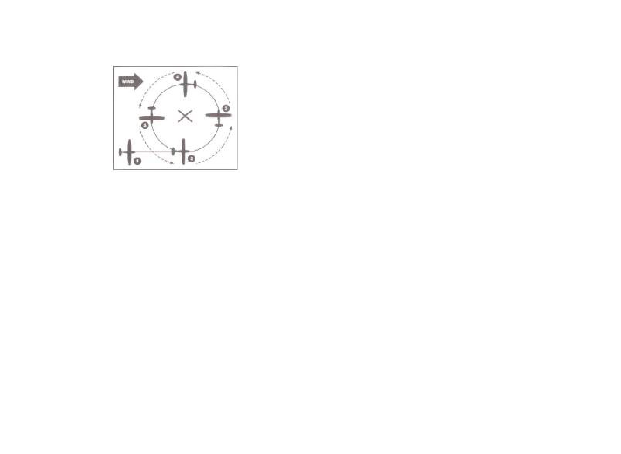
Appendix - A
Ground Reference Maneuvers
Turns Around A Point
1.
Enter on the downwind side of the point of reference.
a.
Power - 2300 RPM
b.
Airspeed ≈ 105 KIAS
c.
Altitude - 800-1000 feet AGL
2.
a.
Once reference point is abeam wing, begin your turn
b.
Steepest bank (45⁰) due to highest ground speed
c.
Maintain distance from reference point using bank control
and remaining coordinated
3.
a.
Maintain distance from reference point
b.
Gradually decrease your bank angle as airplane turns up
wind
c.
Maintain aircraft coordination
4.
a.
Slowest Ground Speed
b.
Shallowest Bank angle
c.
maintain distance from reference point and coordination
5.
a.
Gradually increase bank angle as airplane begins to turn
downwind
b.
Maintain distance from reference point
c.
Fly at least 2 turns, and exit at point of entry at the same
altitude and airspeed at which the maneuver was started
-86-

S-Turns
1.
Enter on the downwind side of the line of reference.
a.
Power - 2300 RPM
b.
Airspeed ≈ 105 KIAS
c.
Altitude - 800-1000 feet AGL
2.
Cross the line feature wings-level
Initial Turn is to the left
This will be the highest ground speed
Steepest bank angle (do not exceed 45⁰)
3.
Moderate bank angle and decreasing as airplane begins turn
upwind. Maintain coordination throughout maneuver
4.
Level wings as you cross the line of reference
5.
Slowest ground speed
Turn in opposite direction
Shallowest bank angle
6.
Moderate bank angle and increasing as airplane begins turn to
downwind. Maintain coordination
7.
Level the wings crossing the line reference
8.
Fastest ground speed
Exit the maneuver at the same altitude and airspeed when
maneuver was started
-87-

Rectangle)Course
7.
Start the turn with a medium bank angle
Reduce bank angle as ground speed slows
8.
Roll out wings level, directly upwind
Turn will be less than 90⁰
9.
Same indicated airspeed, slowest ground speed
Maintain distance from boundary
Crab angle is not required
10.
Start a shallow turn for the slowest ground speed
Gradually increase to a medium bank angle as the ground speed
1.
Select a rectangle course
increases. Roll out wings level with a wind correction angle and
a.
Power - 2300 RPM
crab into the wind.
b.
Airspeed ≈ 105 KIAS
11.
Turn will be less than 90⁰
c.
Altitude - 800-1000 feet AGL
Same indicated airspeed, medium ground speed
d.
Remain ½ to 1 mile outside of selected rectangle course
2.
Enter 45⁰ to downwind with first course to the left
Maintain coordination and crab into the wind
3.
Same KIAS, fastest ground speed
12.
Start a medium bank turn, gradually increasing bank angle as
Maintain distance to boundary
ground speed increases
Crab angle not required
Turn will be more than 90⁰
4.
Steepest turn for fastest ground speed (max 45⁰ bank angle)
Ease off of bank angle as the wind turns to a crosswind, and
Exit at point of entry at the same airspeed and altitude when ma-
ground speed begins to slow
neuver was started
5.
Roll out of the turn wings-level, crabbing into the wind
Turn will be more than 90⁰
6.
Maintain coordination and crab into wind
Same airspeed, medium ground speed
Maintain distance from boundary
-89-
-88-
!
Appendix B
Commercial
Maneuvers

Appendix - B
3.
Crosswind, ground speed decreases
Commercial Maneuvers
If pylon moves forward of your line of sight along the wing tip,
apply forward pressure and descend
Eights on Pylons
Maintain coordination, do not use rudder to “hold” the pylon
4.
Upwind, slowest ground speed
Shallowest bank
Furthest distance from the pylon
Lowest pivotal altitude
5.
Downwind, fastest ground speed
Steepest bank
Closest distance to pylon
Highest pivotal altitude
Cross midpoint of pylons wings level
6.
Just past the left pylon, roll into a left turn to position wing tip on
the pylon
Prevent up-down movement of the pylon using aileron
Prevent fore-aft movement of the pylon using elevator
1.
Select 2 pylons about ½ a mile apart
Follow pylon with the control column
a.
Power - 2300 RPM
7.
Upwind, slowest ground speed
b.
Airspeed ≈ 105 KIAS
Shallowest bank
c.
Altitude - 800-1000 feet AGL
Furthest distance from pylon
d.
Enter maneuver by approach at midpoint of the pylons
Lowest pivotal altitude
diagonally
8.
Downwind, fastest ground speed
2.
Just past the pylon, roll into a right turn to position the wing tip
Steepest bank
on the pylon
Closest distance to pylon
Highest pivotal altitude
a.
Prevent apparent up down movement of the pylon using
aileron
9.
Cross midpoint of pylons wings level
b.
Prevent apparent fore-aft movement of the pylon by using
Repeat the figure 8 pattern
elevator
Exit at point of entry a the same altitude and airspeed when
c.
Follow pylon with the control column
maneuver started
-90-
-91-

Chandelle
3.
Maintain 30⁰ bank angle until 90⁰ point
Continue to increase pitch attitude until 90⁰ point
Maintain full power
Altitude is increasing
Airspeed is decreasing
4.
Gradually start rolling out bank at 90⁰ point
Maintain pitch attitude
Maintain coordination
5.
Complete roll out to wings level at 180⁰ point
Airspeed is approximately 1.2 Vs1 +/- 5 kts (48x1.2= 57 kts)
Momentarily hold airspeed
Maintain coordination
6.
Resume straight and level flight with minimum loss of altitude
Let airspeed build
1.
Find appropriate area to perform maneuver
Reduce power to cruise setting
a.
Power - 2300 RPM
Repeat maneuver to the right
b.
Airspeed ≈ 105 KIAS
c.
Any altitude to allow maneuver to be completed at or
above 1500 feet AGL
2.
Roll into the wind with a 30⁰ bank angle
Pitch airplane up into a climbing turn
Smoothly apply full power, without exceeding max RPM
Once bank angle is established, neutralize ailerons
Maintain coordination
-92-
-93-

4.
Arrive at maximum bank angle 30⁰ at the 90⁰ reference point
Lazy Eights
Pitch attitude is momentarily level
Take note of minimum airspeed
Take note of maximum altitude
Pitch continues to decrease
Bank decreases
Speed increases
5.
Pass the 135⁰ reference point with the lowest nose attitude for
the maneuver
Reduce bank angle through 15⁰
Speed continues to increase
Pitch begins increasing
Bank angle continues to decrease
6.
At the 180⁰ reference point, aircraft is momentarily level
Altitude is same as entry altitude
Airspeed is same as entry airspeed
Begin to raise the nose
Gently roll bank in the opposite direction
7.
Pass the 45⁰ reference point with maximum nose-up for maneuver
Increase the bank angle through 15⁰
Speed is decreasing
1.
Find appropriate area to perform maneuver
Pitch attitude begins decreasing
a.
Power - 2300 RPM
Bank angle continues to increase
8.
Arrive at maximum bank angle of 30⁰ at the 90⁰ reference point
b.
Airspeed ≈ 105 KIAS
Pitch attitude is momentarily level
c.
Any altitude to allow maneuver to be completed at or
Take note of minimum airspeed
above 1500 feet AGL
Take note of maximum altitude
2.
Fly crosswind and select an upwind reference point abeam the
Pitch continues to decrease
wing tip
Bank decreases
Raise the nose above the horizon and begin a climb
Speed increases
9.
Pass the 135⁰ reference point with the lowest nose attitude for maneuver
Slowly roll in bank, and enter a coordinated climbing turn into
the wind
Reduce bank angle through 15⁰
3.
Pass the 45⁰ reference point with maximum nose-up for
Speed continues to increase
maneuver
Pitch begins increasing
Increase bank angle through 15⁰
Bank angle continues to decrease
10.
At the 180⁰ reference point airplane is wings level
Speed is decreasing
Altitude is the same as entry altitude
Pitch attitude begins decreasing
Airspeed is same as entry airspeed
Bank angle continues to increase
Resume straight and level flight
-94-
-95-
Recovery for a Nose High:
Unusual Attitudes
1.
Reduce Pitch - Reducing the pitch will reduce the angle of
The industry definition of unusual attitudes are defined as pitch uninten-
tionally exceeds 25 degrees nose up or 10 degrees nose down, bank
attack almost immediately and will assist in increasing your air-
angle unintentionally exceeds 45 degrees and airspeed and angle of
speed.
attack are inappropriate for the condition.
2.
Add Power - Adding power will assist in increasing your
In general, there are two types of unusual attitudes:
airspeed and helping to prevent a stall.
Nose High and Nose Low.
3.
Level the Wings - Leveling the wings will help to prevent one
Nose High:
wing stalling before another.
1.
Airspeed Indicator - Airspeed will be decreasing rapidly
Note
2.
Altimeter - Altitude is increasing rapidly
It is imperative that you follow these steps in order. They are established
3.
Attitude Indicator - Miniature airplane above the horizon
in order of importance. While step one and step two should be done si-
and usually banked.
multaneously, they are given in this order to establish the importance.
4.
Turn Coordinator - Greater than standard rate turn (Full
deflection)
Recovery from a Nose Low:
5.
Heading Indicator - Depending on the bank of the aircraft,
will be spinning rapidly.
1.
Reduce Power - With a fixed pitch prop we do not want to
over speed the prop. Also, we are attempting to reduce our
Nose Low:
overall airspeed.
1.
Airspeed Indicator - Airspeed will be increasing rapidly
2.
Level the Wings - To prevent a graveyard spiral, it is impera-
2.
Altimeter - Altitude will be decreasing rapidly
tive that you level the wings prior to pitching up.
3.
Attitude Indicator - Miniature airplane below the horizon
3.
Increase Pitch - Increase pitch of aircraft to bring it to a nose
and usually banked.
level attitude. At this point as the airspeed starts to bleed off,
4.
Turn Coordinator - Greater than standard rate turn (Full
increase the power to prevent the aircraft from entering into a
Deflection)
stall.
5.
Heading Indicator - Depending on the bank of the aircraft,
Note
will be spinning rapidly.
It is imperative that you follow these steps in order. They are established
in order of importance. If you attempt to increase pitch prior to leveling
The recovery procedure for unusual attitude is going to depend on
which type of unusual attitude you are experiencing.
the wings you WILL enter a grave yard spiral.
-107-
-108-