Siemens MICROMASTER 410. Operating Instructions
MICROMASTER 410
Operating Instructions
User Documentation
MICROMASTER 410 Documentation
Getting Started Guide
Is for quick commissioning.
Operating Instructions
Gives information about features of the MM410,
Installation, Commissioning, Control modes, System
Parameter structure, Troubleshooting, Specifications
and available options of the MM410.
Parameter List
The Parameter List contains the description of all
Parameters structured in functional order and a
detailed description.
Catalogues
In the catalogue you will find all the necessary
information to select an appropriate inverter, as well
as filters, chokes, operator panels and
communication options.
Overview
1
Installation
2
MICROMASTER 410
Commissioning
3
Using the
4
MICROMASTER 410
Operating Instructions
User Documentation
System Parameters
5
Troubleshooting
6
MICROMASTER 410
7
Specifications
Available options
8
Electro-Magnetic
9
Valid for
Compatibility
Converter Type
Software version
Appendices
A
MICROMASTER 410
V1.6
B
C
Index
Definitions and Warnings
Definitions and Warnings
DANGER
indicates an immiently hazardous situation which, if not avoided, will result in death
or serious injury.
WARNING
indicates a potentially hazardous situation which, if not avoided, could result in
death or serious injury.
CAUTION
used with the safety alert symbol indicates a potentially hazardous situationwhich, if
not avoided, may result in minor or moderate injury.
CAUTION
used without safety alert symbol indicates a potentially hzardous situation which, if
not avoided, may result in a property demage.
NOTICE
indicates a potential situation which, if not avoided, may result in an undesireable
result or state.
NOTES
For the purpose of this documentation, "Note" indicates important information
relating to the product or highlights part of the documentation for special attention.
Qualified personnel
For the purpose of this Instruction Manual and product labels, a "Qualified person"
is someone who is familiar with the installation, mounting, start-up and operation
of the equipment and the hazards involved.
He or she must have the following qualifications:
1. Trained and authorized to energize, de-energize, clear, ground and tag
circuits and equipment in accordance with established safety procedures.
2. Trained in the proper care and use of protective equipment in accordance with
established safety procedures.
3. Trained in rendering first aid.
♦ PE ñ Protective Earth uses circuit protective conductors sized for short circuits
PE
= Ground
where the voltage will not rise in excess of 50 Volts. This connection is
normally used to ground the inverter.
♦
- Is the ground connection where the reference voltage can be the same
as the Earth voltage. This connection is normally used to ground the motor.
Use for intended purpose only
The equipment may be used only for the application stated in the manual and only
in conjunction with devices and components recommended and authorized by
Siemens.
6
Safety Instructions
Safety Instructions
The following Warnings, Cautions and Notes are provided for your safety and as a
means of preventing damage to the product or components in the machines
connected. This section lists Warnings, Cautions and Notes, which apply generally
when handling MICROMASTER 410 Inverters, classified as General, Transport &
Storage, Commissioning, Operation, Repair and Dismantling & Disposal.
Specific Warnings, Cautions and Notes that apply to particular activities are
listed at the beginning of the relevant chapters and are repeated or supplemented
at critical points throughout these sections.
Please read the information carefully, since it is provided for your personal
safety and will also help prolong the service life of your MICROMASTER 410
Inverter and the equipment you connect to it.
General
WARNING
♦ This equipment contains dangerous voltages and controls potentially
dangerous rotating mechanical parts. Non-compliance with Warnings or
failure to follow the instructions contained in this manual can result in loss of
life, severe personal injury or serious damage to property.
♦ Only suitable qualified personnel should work on this equipment, and only
after becoming familiar with all safety notices, installation, operation and
maintenance procedures contained in this manual. The successful and safe
operation of this equipment is dependent upon its proper handling,
installation, operation and maintenance.
♦ Risk of electric shock. The DC link capacitors remain charged for five minutes
after power has been removed. It is not permissible to open the equip-
ment until 5 minutes after the power has been removed.
CAUTION
♦ Children and the general public must be prevented from accessing or
approaching the equipment!
♦ This equipment may only be used for the purpose specified by the
manufacturer. Unauthorized modifications and the use of spare parts and
accessories that are not sold or recommended by the manufacturer of the
equipment can cause fires, electric shocks and injuries.
NOTES
♦ Keep these operating instructions within easy reach of the equipment and
make them available to all users
♦ Whenever measuring or testing has to be performed on live equipment, the
regulations of Safety Code VBG 4.0 must be observed, in particular ß8
ìPermissible Deviations when Working on Live Partsî. Suitable electronic
tools should be used.
♦ Before installing and commissioning, please read these safety instructions
and warnings carefully and all the warning labels attached to the equipment.
Make sure that the warning labels are kept in a legible condition and replace
missing or damaged labels
7
Safety Instructions
Transport & Storage
WARNING
♦ Correct transport, storage, erection and mounting, as well as careful
operation and maintenance are essential for proper and safe operation of the
equipment.
CAUTION
♦ Protect the inverter against physical shocks and vibration during transport and
storage. Also be sure to protect it against water (rainfall) and excessive
temperatures (see table on page 19).
Commissioning
WARNINGS
♦ Work on the device/system by unqualified personnel or failure to comply with
warnings can result in severe personal injury or serious damage to material.
Only suitably qualified personnel trained in the setup, installation,
commissioning and operation of the product should carry out work on the
device/system.
♦ Only permanently-wired input power connections are allowed. This equipment
must be grounded (IEC 536 Class 1, NEC and other applicable standards).
♦ If a Residual Current-operated protective Device (RCD) is to be used, it must
be an RCD type B.
♦ The following terminals can carry dangerous voltages even if the inverter is
inoperative:
- the power supply terminals L and N.
- the motor terminals U, V, W and the terminals DC+ and DC-.
♦ This equipment must not be used as an ëemergency stop mechanismí (see
EN 60204, 9.2.5.4)
CAUTION
The connection of power, motor and control cables to the inverter must be carried
out as shown in Figure 2-10 on page 30, to prevent inductive and capacitive
interference from affecting the correct functioning of the inverter.
8
Safety Instructions
Operation
WARNING
♦ MICROMASTERS operate at high voltages.
♦ When operating electrical devices, it is impossible to avoid applying
hazardous voltages to certain parts of the equipment.
♦ Emergency Stop facilities according to EN 60204 IEC 204 (VDE 0113) must
remain operative in all operating modes of the control equipment. Any
disengagement of the Emergency Stop facility must not lead to uncontrolled
or undefined restart.
♦ Wherever faults occurring in the control equipment can lead to substantial
material damage or even grievous bodily injury (i.e. potentially dangerous
faults), additional external precautions must be taken or facilities provided to
ensure or enforce safe operation, even when a fault occurs (e.g. independent
limit switches, mechanical interlocks, etc.).
♦ Certain parameter settings may cause the inverter to restart automatically
after an input power failure.
♦ Motor parameters must be accurately configured for motor overload
protection to operate correctly.
♦ This equipment is capable of providing internal motor overload protection in
accordance with UL508C section 42. Refer to P0610 and P0335, I2t is ON by
default.
♦ This equipment is suitable for use in a circuit capable of delivering not more
than 10,000 symmetrical amperes (rms), for a maximum voltage of
115 V/230 V, when protected by a H or K type fuse.
♦ This equipment must not be used as an ëemergency stop mechanismí (see
EN 60204, 9.2.5.4)
Repair
WARNING
♦ Repairs on equipment may only be carried out by Siemens Service, by
repair centers authorized by Siemens or by qualified personnel who are
thoroughly acquainted with all the warnings and operating procedures
contained in this manual.
♦ Any defective parts or components must be replaced using genuine Siemens
authorised parts.
♦ Risk of electric shock. Wait 5 minutes for the DC capacitors to discharge
before carrying out any installation work.
Dismantling & Disposal
NOTES
♦ The inverterís packaging is re-usable. Retain the packaging for future use or
return it to the manufacturer.
♦ Easy-to-release screw and snap connectors allow you to break the unit down
into its component parts. You can then re-cycle these component parts,
dispose of them in accordance with local requirements or return them to
the manufacturer.
9
Table of Contents
Table of Contents
1
Overview
15
1.1
The MICROMASTER 410
15
1.2
Features
15
2
Installation
17
2.1
General
18
2.2
Power Losses
19
2.3
Ambient operating conditions
19
2.4
Harmonic Currents
21
2.5
Derating with Pulse Frequencies
21
2.6
Overvoltage and Trip Levels
22
2.7
Mechanical Installation
22
2.8
Electrical Installation
26
3
Commissioning
31
3.1
Block Diagram
32
3.2
Commission Modes
33
3.3
General operation
42
4
Using the MICROMASTER 410
45
4.1
Frequency Setpoint (P1000)
45
4.2
Command Sources (P0700)
46
4.3
OFF and braking Functions
46
4.4
Control Modes (P1300)
48
4.5
Faults and Alarms
48
5
System Parameters
49
5.1
Introduction to MICROMASTER System Parameters
49
5.2
Parameter Overview
50
5.3
Parameter List (short form)
51
6
Troubleshooting
57
6.1
Troubleshooting with the Standard Inverter LED
57
6.2
Troubleshooting with the Operator Panel (OP)
57
6.3
Fault messages
58
6.4
Alarms
60
7
MICROMASTER 410 Specifications
63
11
Table of Contents
8
Options
67
8.1
Variant Independent Options
67
8.2
Variant Dependent Options
67
9
Electro-Magnetic Compatibility (EMC)
69
9.1
Electro-Magnetic Compatibility (EMC)
69
Appendices
75
A
Fitting the Operator Panel
75
B
Applicable Standards
76
C
List of Abbreviations
77
Index
................................................................................................................................. 78
12
Table of Contents
List of Illustrations
Figure 2-1
Forming
18
Figure 2-2
Power Losses, 230 V
19
Figure 2-3
Derating for Altitude
19
Figure 2-4
Dimensions of the MICROMASTER 410
22
Figure 2-5
Clearance distances for mounting the inverter
23
Figure 2-6
Mounting Brackets
24
Figure 2-7
Position of ëYí Capacitor Link
28
Figure 2-8
MICROMASTER 410 Connection Terminals
28
Figure 2-9
Motor and Power Connections
29
Figure 2-10
Wiring Guidelines to Minimize the Effects of EMI
30
Figure 3-1
Inverter block diagram
32
Figure 3-2
Operator Panel for the MICROMASTER 410 Inverter
33
Figure 3-3
Basic operation
34
Figure 3-4
Changing the Line Supply Frequency
35
Figure 3-5
Buttons on the Operator Panel
37
Figure 3-6
Changing parameters via the OP
38
Figure 3-7
Typical Motor Rating Plate Example
41
Figure 3-8
Motor Overload PTC Connection
43
Figure 5-1
Parameter Overview
50
List of Tables
Table 2-1
Single Phase 115 V Connection
21
Table 2-2
Single Phase 230 V Connection
21
Table 2-3
Derating with Pulse Frequencies
21
Table 2-4
Trip Levels
22
Table 2-5
Dimensions and Torques of MM410
23
Table 3-1
Default settings for operation using the standard inverter
34
Table 3-2
Default settings for operation using the OP
36
Table 7-1
MICROMASTER 410 Performance Ratings
63
Table 7-2
Terminal Torques ñ Field Wiring Connectors
64
Table 7-3
MICROMASTER 410 Specifications
64
Table 9-1
Case 1 - General Industrial
71
Table 9-2
Case 2 - Filtered Industrial
71
Table 9-3
Case 3 - Filtered for Residential, Commercial and Light Industry
72
Table 9-4
Compliance Table
72
13
1 Overview
1
Overview
1.1
The MICROMASTER 410
The MICROMASTER 410s are a range of frequency inverters for controlling the
speed of three phase AC motors. The various models available range from 120 W
to 750 W single-phase input.
The inverters are microprocessor-controlled and use state-of-the-art Insulated Gate
BipoIar Transistor (IGBT) technology. This makes them reliable and versatile. A
special pulse-width modulation method with selectable pulse frequency permits
quiet motor operation. Comprehensive protective functions provide excellent
inverter and motor protection.
The MICROMASTER 410 with its default factory settings is ideal for a large range
of simple motor control applications.
The MICROMASTER 410 can be used in both 'stand-alone' applications as well as
being integrated into 'Automation Systems'.
1.2
Features
Main Characteristics
Easy installation
Easy commissioning
Rugged EMC design
Can be operated on IT line supplies
Fast repeatable response time to control signals
Comprehensive range of parameters enabling configuration for a wide range of
applications
Simple cable connection
Relay output
3 digital inputs
1 Analog input - AIN1: 0 ñ 10 V
The analog input can be used as the 4th digital input
High pulse frequencies for low-noise motor operation
Status information and alarm messages with the optional Operator Panel
External options for PC communications, Operator Panel
15
1 Overview
Performance Characteristics
Flux Current Control (FCC) for improved dynamic response and motor control
Fast Current Limitation (FCL) for trip-free operation
Built-in DC injection brake
Compound braking to improve braking performance
Acceleration/deceleration times with programmable smoothing
Selectable up and down ramps
4-point ramp smoothing
Multi-point V/f characteristic
150 % overload for 60 seconds
Automatic restart after a mains failure
Start-on-the-fly
Protection Characteristics
Overvoltage/undervoltage protection
Overtemperature protection for the inverter
Ground fault protection
Short-circuit protection
I2t thermal motor protection
Motor stall prevention
16
2 Installation
2
Installation
WARNING
♦ Work on the device/system by unqualified personnel or failure to comply with
warnings can result in severe personal injury or serious damage to material.
Only suitably qualified personnel trained in the setup, installation,
commissioning and operation of the product should carry out work on the
device/system.
♦ Only permanently-wired input power connections are allowed. This
equipment must be grounded (IEC 536 Class 1, NEC and other applicable
standards).
♦ If a Residual Current-operated protective Device (RCD) is to be used, it must
be an RCD type B.
♦ The following terminals can carry dangerous voltages even if the inverter is
inoperative:
- the power supply terminals L and N
- the motor terminals U, V, W and the terminals DC+ and DC-
♦ Always wait 5 minutes to allow the unit to discharge after switching off before
carrying out any installation work.
♦ This equipment must not be used as an ëemergency stop mechanismí (see
EN 60204, 9.2.5.4)
♦ The minimum size of the earth-bonding conductor must be equal to or greater
than the cross-section of the power supply cables.
♦ Safety regulations must not be compromised when installing inverters!
CAUTION
The connection of power, motor and control cables to the inverter must be carried
out as shown in Figure 2-10 on page 30, to prevent inductive and capacitive
interference from affecting the correct functioning of the inverter.
17
2 Installation
2.1
General
Installation after a Period of Storage
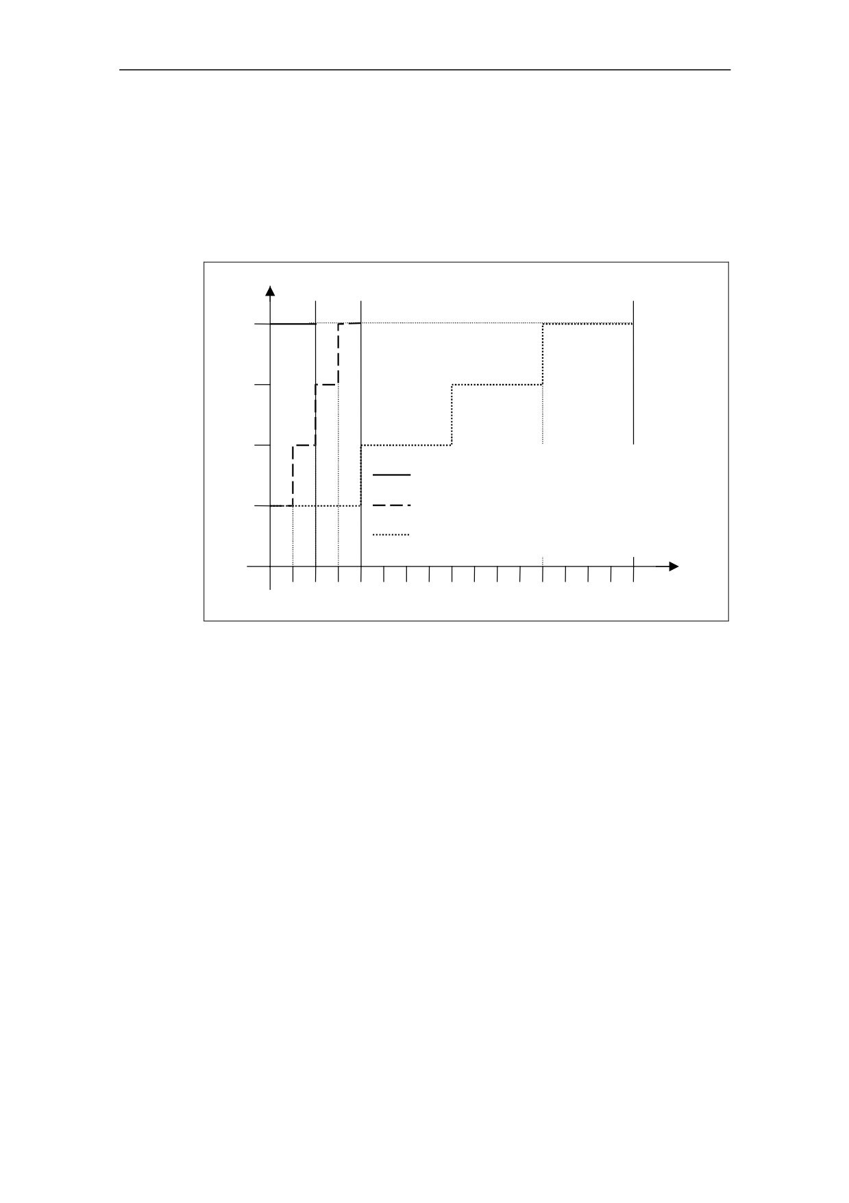
Following a prolonged period of storage, you must reform the capacitors in the
inverter. It is important that the time of storage is calculated from the time of
manufacture and not the time of delivery. The requirements are listed below.
Voltage
[%]
100
75
50
Storage period less than 1 year:
No action necessary
Storage period 1 to 2 years
Prior to energizing, connect to
voltage for one hour
Storage period 2 to 3 years
Prior to energizing, form
according to the curve
Storage period 3 and more years Prior to energizing, form
according to the curve
Time t [h]
0,5
1
2
4
6
8
Figure 2-1
Forming
The serial numbers consist 13 characters and contains the date of manufacture,
e.g. XAM214-123456
XAM214-123456 Characters 1-2 are the site where the product is built
XAM214-123456 Character 3 denotes the year eg. M = 2000
XAM214-123456 Character 4 is the month (1-9 =Jan-Sep, O =Oct, N =Nov, D =Dec)
XAM214-123456 Characters 5-6 are the day of the month
XAM214-123456 Character 7 is a seperator
XAM214-123456 Characters 8-13 are the sequential serial number 1-999999
18
2 Installation
2.2
Power Losses
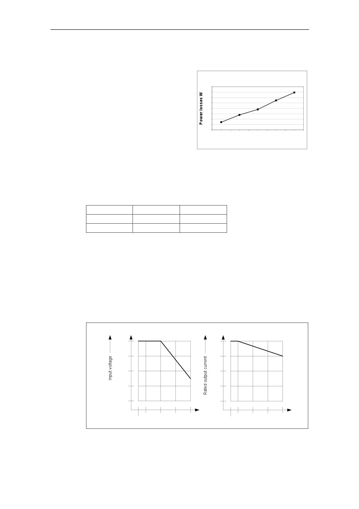
Figure 2-2 shows the power loss for
230V MM410 Power losses
the MICROMASTER 410 Inverter.
The graph can be used to read the
80
70
loss at full load of a particular variant.
60
50
40
30
20
10
0
0,12
0,25
0,37
0,55
0,75
Power output kW
Figure 2-2
Power Losses, 230 V
2.3
Ambient operating conditions
Temperature
Frame Size
AA
AB
Min. [°C]
-10
-10
Max. [°C]
50
50
For UL compliance the maximum surrounding air temperature for 230 V / 750 W
and 115 V / 550 W inverters is 40 ºC, for all other inverters 50 ºC.
Humidity Range
Relative air humidity ≤ 95 % Non-condensing
Altitude
If the inverter is to be installed at an altitude > 1000 m or > 2000 m above sea
level, derating will be required.
Figure 2-3 below shows the permissible rated input voltages and output current for
inverter installations from 500 m to 4000 m above sea level.
Permissible rated input voltage
Permissible rated output current
as a percentage of the nominal voltage
as a percentage of the nominal current
100
100
90
90
80
80
70
70
60
60
1000
2000
3000
4000
1000
2000
3000
4000
500
500
Installation altitude in metres above sea level
Figure 2-3
Derating for Altitude
19
2 Installation
Shock
Do not drop the inverter or expose to sudden shock. Do not install the inverter in an
area where it is likely to be exposed to constant vibration.
Mechanical strength to EN 60721-3-3
Deflection:
0.075 mm (10 ... 58 Hz)
Acceleration:
10 m/s2 (58 ... 200 Hz)
Vibration
Do not install the inverter in an area where it is likely to be exposed to constant
vibration.
Electromagnetic Radiation
Do not install the inverter near sources of electromagnetic radiation.
Atmospheric Pollution
Do not install the inverter in an environment, which contains atmospheric pollutants
such as dust, corrosive gases, etc.
Water
Take care to site the inverter away from potential water hazards, e.g. do not install
the inverter beneath pipes that are subject to condensation. Avoid installing the
inverter where excessive humidity and condensation may occur.
Installation and cooling
CAUTION
The inverter can be front or side mounted, but MUST be installed in a vertical
position. Mount the inverter vertically to ensure optimum cooling, see Figure 2-5
on page 23.
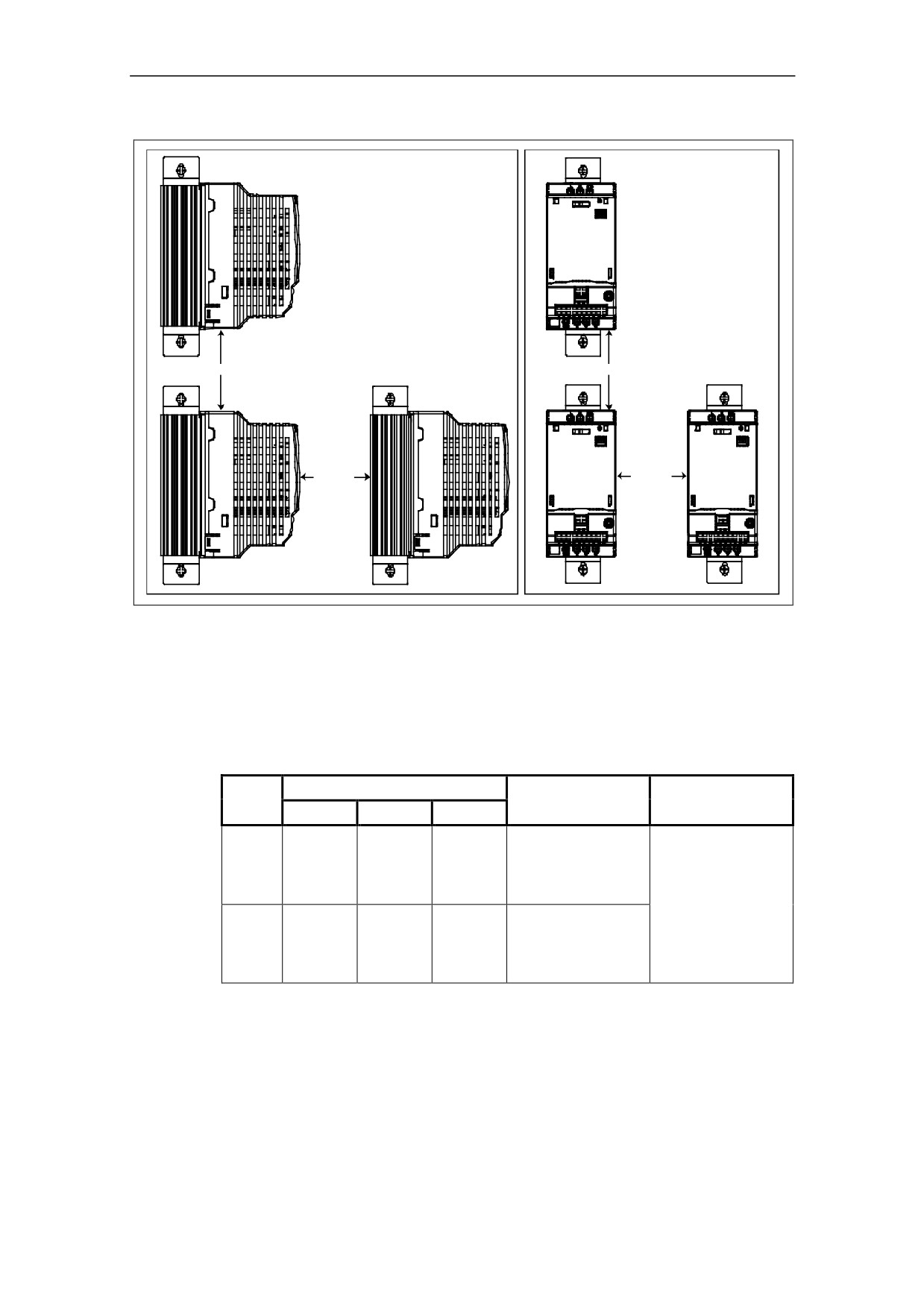
Ensure that the inverterís air vents are not obstructed. Allow 100 mm clearance
above and below the inverter. A clearance of 30 mm on both sides of the inverter is
also required.
20
2 Installation
2.4
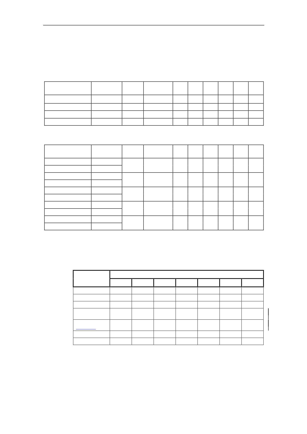
Harmonic Currents
Harmonic currents with 1% mains impedance.
Table 2-1
Single Phase 115 V Connection
Power
Fundamen-
3rd
5th
7th
9th
11th
13th
MLFB
Filter Type
CT (kW)
tal Amps
Amps
Amps
Amps
Amps
Amps
Amps
6SE6410-2UA11-2AA0
UNFILTERED
0,12
2,90
2,80
2,60
2,35
2,00
1,68
1,30
6SE6410-2UA12-5AA0
UNFILTERED
0,25
5,65
5,30
4,68
3,80
2,87
1,98
1,27
6SE6410-2UA13-7AA0
UNFILTERED
0,37
7,94
7,32
6,07
4,57
3,05
1,87
1,24
6SE6410-2UA15-5BA0
UNFILTERED
0,55
11,25
10,10
8,06
5,67
3,50
2,00
1,58
Table 2-2
Single Phase 230 V Connection
Power
Fundamen-
3rd
5th
7th
9th
11th
13th
MLFB
Filter Type
CT (kW)
tal Amps
Amps
Amps
Amps
Amps
Amps
Amps
6SE6410-2BB11-2AA0
B
0,12
1,34
1,20
0,83
0,45
0,18
0,12
0,06
6SE6410-2UB11-2AA0
UNFILTERED
6SE6410-2BB12-5AA0
B
0,25
2,90
2,40
1,70
0,95
0,40
0,20
0,20
6SE6410-2UB12-5AA0
UNFILTERED
6SE6410-2BB13-7AA0
B
0,37
4,10
3,50
2,50
1,40
0,60
0,25
0,25
6SE6410-2UB13-7AA0
UNFILTERED
6SE6410-2BB15-5BA0
B
0,55
5,30
4,60
3,30
1,80
0,70
0,40
0,40
6SE6410-2UB15-5BA0
UNFILTERED
6SE6410-2BB17-5BA0
B
0,75
7,30
6,50
4,40
2,50
1,00
0,50
0,50
6SE6410-2UB17-5BA0
UNFILTERED
2.5
Derating with Pulse Frequencies
Table 2-3
Derating with Pulse Frequencies
Power
Measured Output Current (A)
(kW)
4 kHz
6 kHz
8 kHz
10 kHz
12 kHz
14 kHz
16 kHz
0.12
0.9
0.9
0.9
0.8
0.7
0.6
0.5
0.25
1.7
1.7
1.7
1.5
1.3
1.1
0.9
0.37
2.3
2.3
2.3
2.0
1.7
1.5
1.3
0.55
3.0
3.0
2.7
2,5
2.2
2.0
1.7
(115V,50°C)
0.55
3.2
3.2
3.2
2.9
2.6
2.3
2.0
(115V,40°C)
0.75
3.9
3.9
3.6
3.2
2.9
2.6
2.3
0.75 (40º C)
4.2
4.2
4.2
3.8
3.4
3.0
2.7
All currents are rated at 50 ºC unless otherwise stated
21
2 Installation
2.6
Overvoltage and Trip Levels
The inverter will protect itself from both supply overvoltage and undervoltage. Trip
levels are show in Table 2-4. Internal overvoltage can occur during braking where
internal voltages are forced high by energy from an external load.
Table 2-4
Trip Levels
Input
Undervoltage
Overvoltage trip
Supplies
trip levels
levels
1 Phase 230 V
115 V
290 V
1 Phase 115 V
60 V
145 V
2.7
Mechanical Installation
Warning
♦ THIS EQUIPMENT MUST BE GROUNDED.
♦ To ensure the safe operation of the equipment, it must be installed and
commissioned by qualified personnel in full compliance with the warnings laid
down in these operating instructions.
♦ Take particular note of the general and regional installation and safety
regulations regarding work on dangerous voltage installations (e.g. EN
50178), as well as the relevant regulations regarding the correct use of tools
and personal protective equipment (PPE).
♦ The mains input, DC and motor terminals, can carry dangerous voltages even
if the inverter is inoperative; wait 5 minutes to allow the unit to discharge after
switching off before carrying out any installation work.
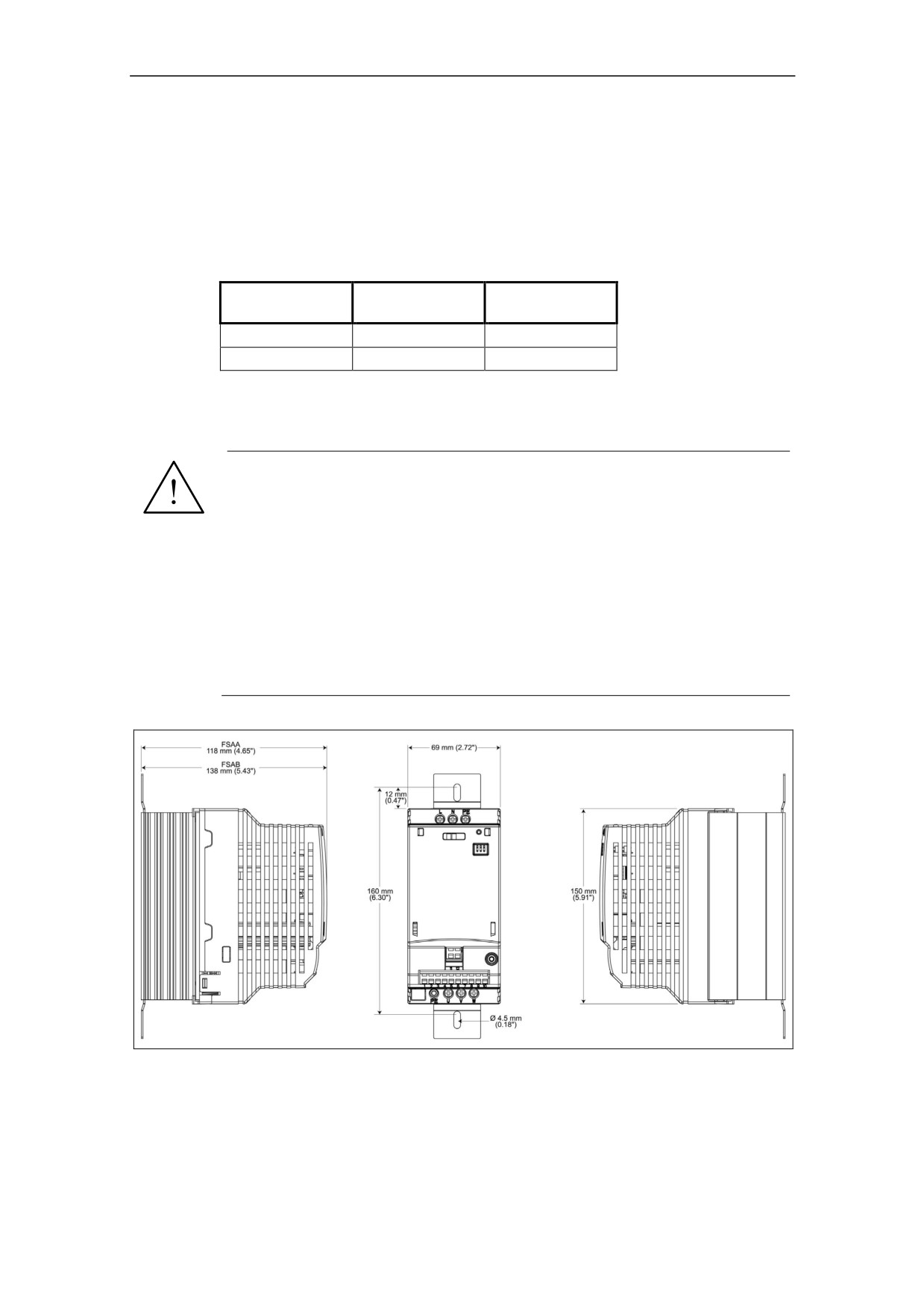
Figure 2-4
Dimensions of the MICROMASTER 410
22
2 Installation
100 mm
100 mm
30 mm
30 mm
Figure 2-5
Clearance distances for mounting the inverter
For side mounting and UL compliance the ambient temperature should be no
greater than 40 ºC. The maximum output current of the 750 W inverter is 3.2 A.
Table 2-5
Dimensions and Torques of MM410
Frame
Overall Dimensions
Tightening Torque
Fixing Method
Size
of fixings
Height
Width
Depth
2 x M4 Bolts*
150 mm
69 mm
118 mm
2 x M4 Nuts*
2.5 Nm
AA
2 x M4 Washers*
(5.91î)
(2.72î)
(4.65î)
with washers fitted
or
Connecting to DIN rail**
2 x M4 Bolts*
2 x M4 Nuts*
150 mm
69 mm
138 mm
2.5 Nm
AB
2 x M4 Washers*
(5.91î)
(2.72î)
(5.43î)
with washers fitted
or
Connecting to DIN rail**
Not supplied with the inverter.
** The DIN rail mounting kit is an optional extra which must be ordered separately. For details see
Section 2.7.2 on page 25.
23
2 Installation
2.7.1
Mounting Brackets
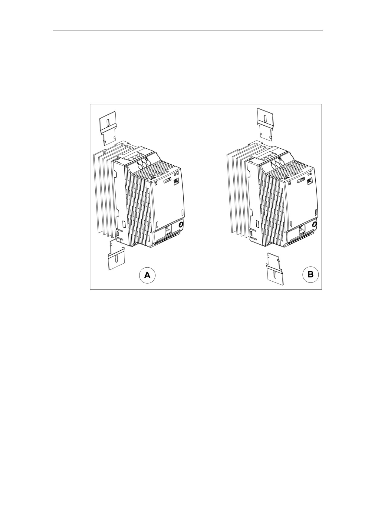
The MICROMASTER 410 can be mounted using mounting brackets, which are
slotted into the heatsink at the rear of the inverter for normal mounting position (see
Figure 2-6 A. For side mounting of the inverter the brackets are slotted into the
heatsink as shown in Figure 2-6 B.
Figure 2-6
Mounting Brackets
24
2 Installation
2.7.2
DIN Rail Mounting
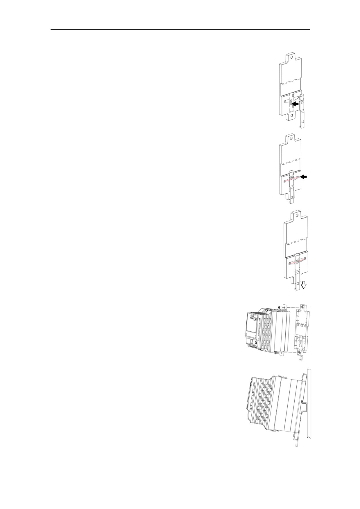
A
The DIN Rail Mounting Kit consists of the following items:
1 x plastic moulded base
1 x plastic moulded retaining clip
1 x Metal spring
The DIN Rail Mounting Kit is supplied as an option for the inverter. If
a mounting kit is required it can be ordered using the following order
number:
6SE6400-0DR00-0AA0
In order to fit the DIN Rail Mounting Kit to the inverter, the kit
B
must first be assembled using the following procedure:
1. The retaining clip is fitted into the recess of the plastic
moulded base, as shown in Drawing A.
2. The spring is fitted into the base as shown in Drawing B.
3. Ensure that the spring is secured to the retaining clip as shown in
Drawing B.
4. Ensure that the retaining clip can be moved in a downward
direction, as shown in Drawing C.
When the retaining clip is released, it should return to its
C
normal position in an upward direction. If it does not, the
spring has been fitted incorrectly.
In order to fit the DIN Rail Mounting Kit to the inverter the following
procedure should be performed:
1. The base is fitted to the inverter using 2 x M5 screws, as shown in
Drawing D.
2. Ensure that the base is securely fastened to the inverter without
causing any damage to the moulded plastic base.
Ensure that the base is securely fastened to the
inverter without causing any damage to the moulded
D
plastic base.
1. Clip the top recess of the base onto the DIN rail,
as shown in Drawing E.
2. The inverter can now be pushed and locked onto the
DIN rail.
The inverter can be removed from the DIN rail by pulling
the retaining clip in a downward direction.
E
25
2 Installation
2.8
Electrical Installation
WARNING
THIS EQUIPMENT MUST BE GROUNDED.
♦ To ensure the safe operation of the equipment, it must be installed and
commissioned by qualified personnel in full compliance with the warnings laid
down in these operating instructions.
♦ Take particular note of the general and regional installation and safety regu-
lations regarding work on dangerous voltage installations (e.g. EN 50178), as
well as the relevant regulations regarding the correct use of tools and
personal protective gear.
♦ The mains input, DC and motor terminals, can carry dangerous voltages even
if the inverter is inoperative; wait 5 minutes to allow the unit to discharge after
switching off before carrying out any installation work.
♦ The inverters can be installed in a side-by-side configuration with a minimum
distance of 30 mm (1.18 inches) between units and a distance of 100 mm
(3.94 inches) must be maintained if the inverters are installed on top of each
other.
CAUTION
The control, power supply and motor leads must be laid separately. Do not feed
them through the same cable conduit/trunking. Never use high voltage insulation
test equipment on cables connected to the inverter.
2.8.1
General
WARNING
The inverter must always be grounded.
If the inverter is not grounded correctly, extremely dangerous conditions may
arise within the inverter, which could prove potentially fatal.
Operation with ungrounded (IT) supplies
The MICROMASTER will operate from ungrounded supplies and will continue to
operate if an output phase is shorted to ground.
On ungrounded supplies, it will be necessary to cut the ëYí capacitor link from the
inside of the unit. The procedure for removing this capacitor is described on page
28 (Figure 2-7) of this manual.
26
2 Installation
Operation with Residual Current Device
If an RCD (also referred to as ELCB or RCCB) is fitted, the MICROMASTER
inverters will operate without nuisance tripping, provided that:
A type B RCD is used.
The trip limit of the RCD is 30 mA.
The neutral of the supply is grounded.
Only one inverter is supplied from each RCD.
The output cables are less than 30 m [98.43 ft](screened) or 50 m [164.04 ft]
(unscreened).
Operation with long cables
All inverters will operate at full specification with cable lengths up to 30 m [98.43 ft]
(screened) or 50 m [164.04 ft] (unscreened).
2.8.2
Power and motor connections
WARNING
♦ Isolate the mains electrical supply before making or changing connections to
the unit.
♦ Ensure that the inverter is configured for the correct supply voltage:
single-phase 230 V MM410 MICROMASTERS must not be connected to a
higher voltage supply.
♦ The 115 V unit MUST only be connected to a 115 V supply.
♦ When synchronous motors are connected or when connecting several motors
in parallel, the inverter must be operated with voltage/frequency control
characteristic (P1300 = 0, 2 or 3).
NOTICE
♦ Ensure that the appropriate circuit-breakers/fuses with the specified current
rating are connected between the power supply and inverter (see Tables
starting on page 63).
♦ Use Class 1 60/75oC copper wire only (16 AWG minimum for UL
compliance). For 115 V units use class 1 75 °C copper wire only. For
tightening torque see Table 7-2 on page 64.
♦ To tighten up the power terminal screws use a 4 - 5 mm cross-tip screwdriver.
27
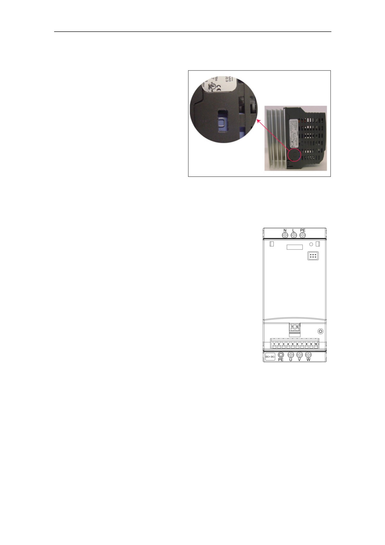
2 Installation
Removal of ëYí Capacitor Link
To use the inverter on
ungrounded supplies the ëYí
capacitor (cap) link must be
removed as follows:
1. Ensure the inverter has
been disconnected from
all power supplies.
2. Locate the ëYí Cap cover
on the left side of the unit
near the rating label.
3. Carefully remove the ëYí
Cap cover.
4. Cut the ëYí Cap link with
an appropriate pair of
Figure 2-7
Position of ëYí Capacitor Link
wire-cutters.
5. After removal of the cover
the degree of protection is IP00.
Access to the power and motor terminals
Please refer to the photographs showing the
Power Terminal connections and the Control
Terminal connections on the inside of the
back cover of this manual.
Connect the power and motor connections
as shown below.
For access to the DC+/DC- terminals the cut-
out cover must be removed. The terminal
connection consists of two spades
measuring 6.3 mm by 0.8 mm. With the cut-
out cover removed and not connections fitted
to the spades, the inverter has only IP00
protection.
The connection of the DC link can be used
for two inverters, with two motors which work
on a revolving advertising media or similar
application:
one inverter is in motor mode and the other
Figure 2-8
MICROMASTER 410
is in regenerative mode.
Connection Terminals
28
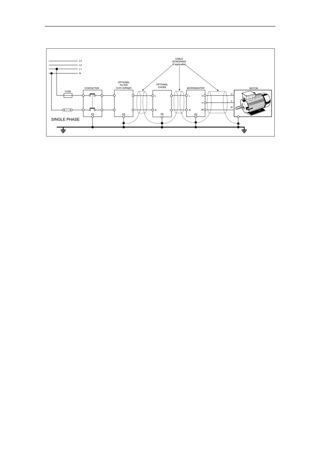
2 Installation
Figure 2-9
Motor and Power Connections
2.8.3
Avoiding Electro-Magnetic Interference (EMI)
The inverters are designed to operate in an industrial environment where a high
level of EMI can be expected. Usually, good installation practices will ensure safe
and trouble-free operation. If you encounter problems, follow the guidelines stated
below.
Action to Take
Ensure that all equipment in the cubicle is well grounded using short, thick
grounding cable connected to a common star point or busbar.
Make sure that any control equipment (such as a PLC) connected to the
inverter is connected to the same ground or star point as the inverter via a
short thick link.
Connect the return ground from the motors controlled by the inverters directly
to the ground connection (PE) on the associated inverter.
Flat grounding conductors are preferred as they have lower impedance at
higher frequencies.
Terminate the ends of the cable neatly, ensuring that unscreened wires are as
short as possible.
Separate the control cables from the power cables as much as possible, using
separate trunking, cross them if necessary at 90º to each other.
Whenever possible, use screened leads for the connections to the control
circuitry.
Ensure that the contactors in the cubicle are suppressed, either with R-C
suppressors for AC contactors or 'flywheel' diodes for DC contactors fitted to
the coils. Varistor suppressors are also effective. This is important when the
contactors are controlled from the inverter relay.
Use screened or armored cables for the motor connections and ground the
screen at both ends using the cable clamps.
29
2 Installation
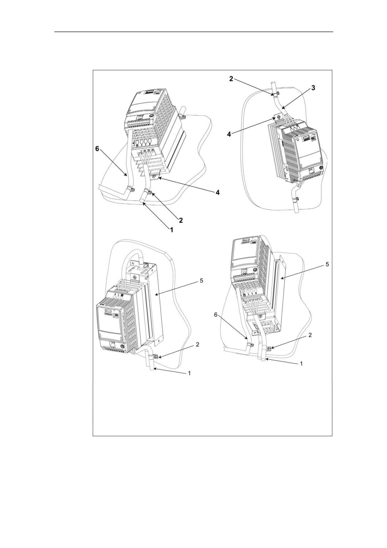
The inverter can be screened using the methodology shown in Figure 2-10.
Legend
1
Motor cable
2
Use suitable clips to fix motor and control cable screens securely to metal back plate
3
Mains power cable
4
Metal mounting brackets
5
Line commutating Choke
6
Control cable
Figure 2-10
Wiring Guidelines to Minimize the Effects of EMI
30
3 Commissioning
3
Commissioning
WARNING
♦ MICROMASTERS operate at high voltages.
♦ When operating electrical devices, it is impossible to avoid applying
hazardous voltages to certain parts of the equipment.
♦ Emergency Stop facilities according to EN 60204 IEC 204 (VDE 0113) must
remain operative in all operating modes of the control equipment. Any
disengagement of the Emergency Stop facility must not lead to uncontrolled
or undefined restart.
♦ Wherever faults occurring in the control equipment can lead to substantial
material damage or even grievous bodily injury (i.e. potentially dangerous
faults), additional external precautions must be taken or facilities provided to
ensure or enforce safe operation, even when a fault occurs (e.g. independent
limit switches, mechanical interlocks, etc.).
♦ Certain parameter settings may cause the inverter to restart automatically
after an input power failure.
♦ Motor parameters must be accurately configured for motor overload
protection to operate correctly.
♦ This equipment is capable of providing internal motor overload protection in
accordance with UL508C section 42. Refer to P0610 and P0335, I2t is ON by
default.
♦ This equipment is suitable for use in a circuit capable of delivering not more
than 10,000 symmetrical amperes (rms), for a maximum voltage of
115 V / 230 V, when protected by a H or K type fuse.
♦ This equipment must not be used as an ëemergency stop mechanismí (see
EN 60204, 9.2.5.4)
CAUTION
Only qualified personnel may enter settings in the control panels. Particular
attention must be paid to safety precautions and warnings at all times.
31
3 Commissioning
3.1
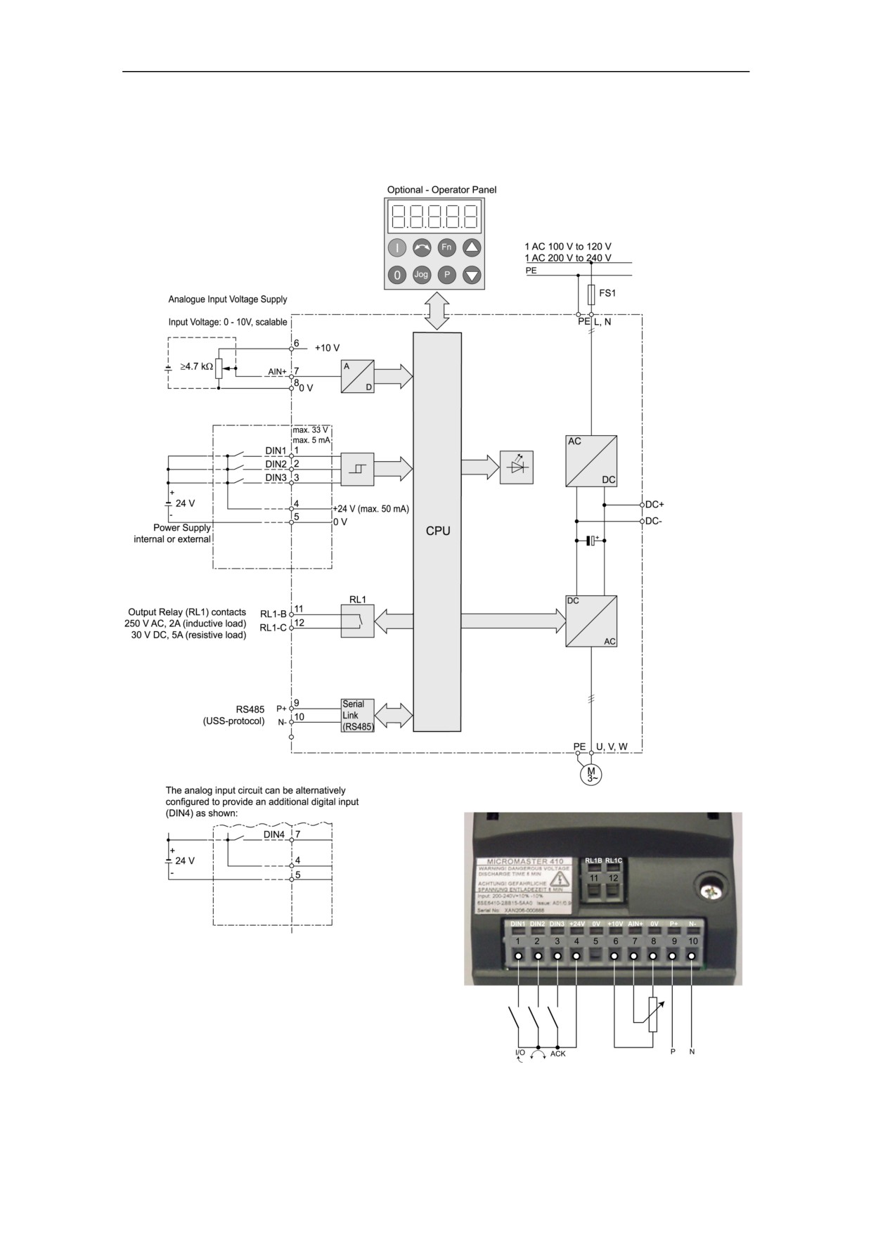
Block Diagram
Figure 3-1
Inverter block diagram
RS485
USS-protocol
32
3 Commissioning
3.2
Commission Modes
The MICROMASTER 410 is supplied with default parameter settings cover the
following:
The motor rating data; voltage, current and frequency data is keyed into the
inverter to ensure that the motor is compatible with the inverter. (A standard
Siemens motor is recommended).
Linear V/f motor speed, controlled by an analogue potentiometer.
Maximum speed 3000 min-1 with 50 Hz (3600 min-1 with 60 Hz); controllable
using a potentiometer via the inverterís analogue inputs.
Ramp-up time / Ramp-down time = 10 s.
If more complex application settings are required, please refer to the Parameter
List.
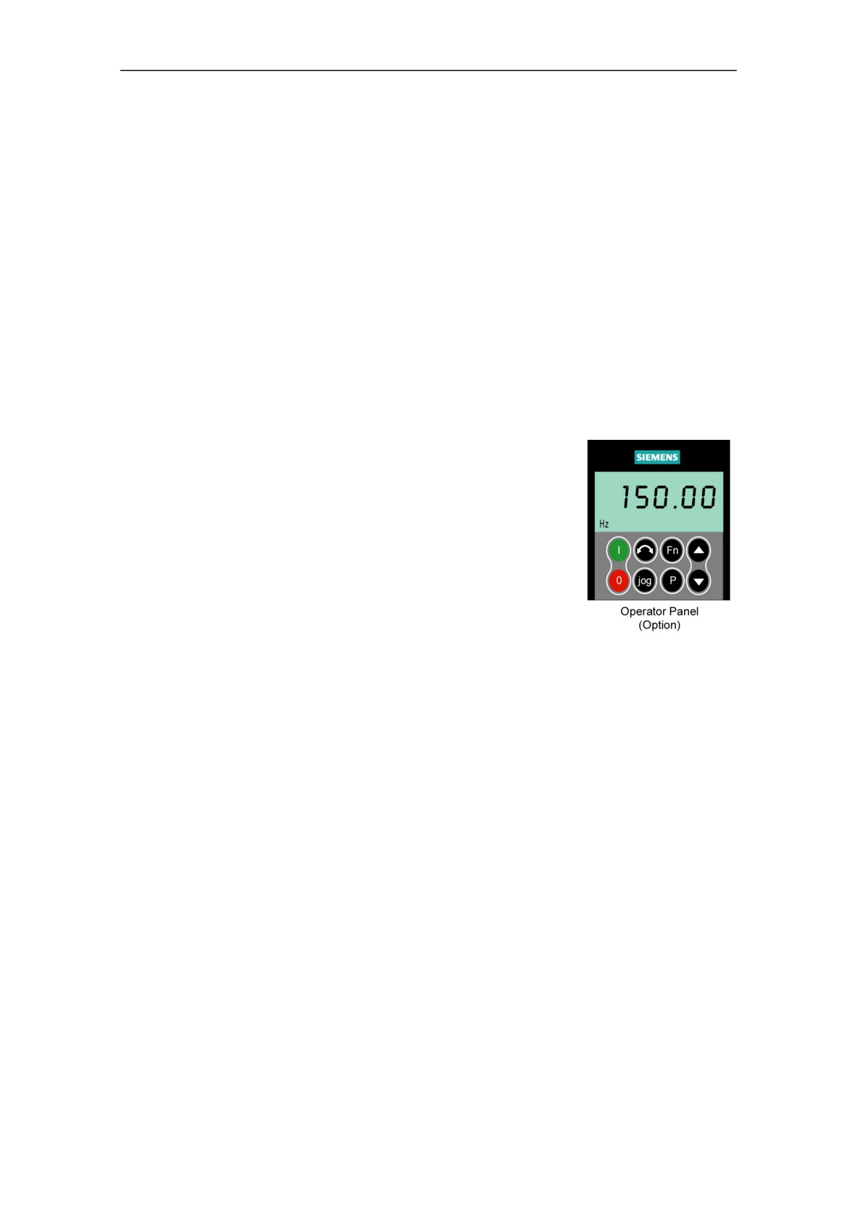
Front Panels for the MICROMASTER 410
For instructions on how to exchange/replace
the Operator Panels, please refer to the
appropriate Appendix A in this manual.
To change the parameters of the inverter you
will require the optional Operator Panel. To
assist in the quick and efficient changing of
parameters, commissioning software tools
such as DriveMonitor can be used; this
software is supplied on the CD-ROM and can
also be downloaded from the Internet.
To allow the parameters to be changed using
the software tools, the PC to Inverter
Figure 3-2
Operator Panel for the
Connection Kit is required.
MICROMASTER 410
Inverter
33
3 Commissioning
3.2.1
Commissioning without an Operator Panel
The inverter is supplied with an LED to indicate the operation state of the unit.
The inverter can be used with its default settings, for a number of applications. The
default settings are shown in Table 3-1.
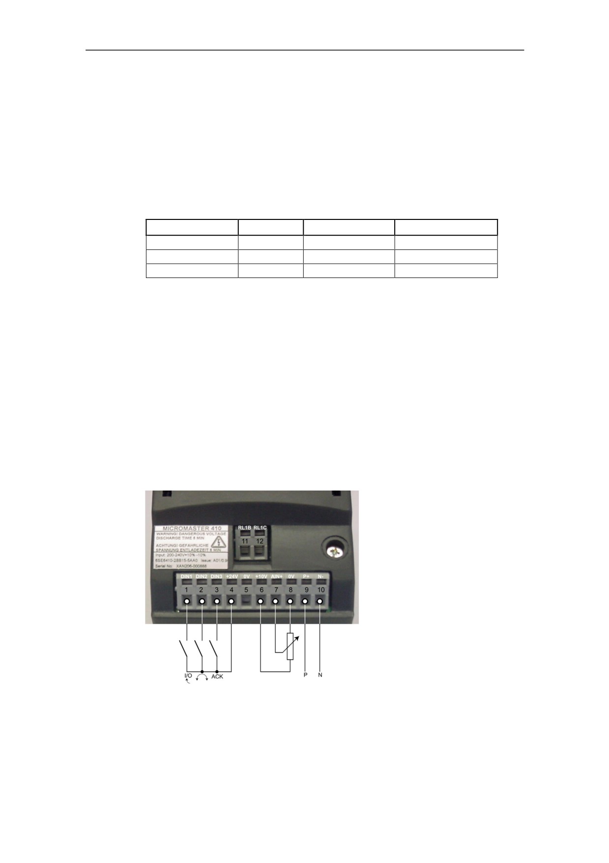
The terminal layout is shown in the photograph of the Control Terminal
Connections on the inside of the back cover of this manual.
Table 3-1
Default settings for operation using the standard inverter
Terminals
Parameter Default
Default Operation
Digital Input 1
1
P0701 = ë1í
ON/OFF1
Digital Input 2
2
P0702 = ë12í
Reverse
Digital Input 3
3
P0703 = ë9í
Fault Acknowledge
Warnings and faults states on the Inverter
The LED indicates the operating status of the inverter. The LED also indicate
various warnings or fault states. In section 6.1 on page 57 the inverter states,
indicated by the LED are explained.
3.2.2
Basic operation
With the default settings of the inverter the following is possible:
Start and stopping the motor (DIN1 via external switch)
Reversing the motor (DIN2 via external switch)
Fault Acknowledgement (DIN3 via external switch)
Controlling the speed of the motor is accomplished by connecting the analog inputs
as shown in the Figure 3-3 (Switches and potentiometers are not supplied with the
inverter).
RS485
USS-protocol
Figure 3-3
Basic operation
34
3 Commissioning
3.2.3
Changing the Line Supply Frequency
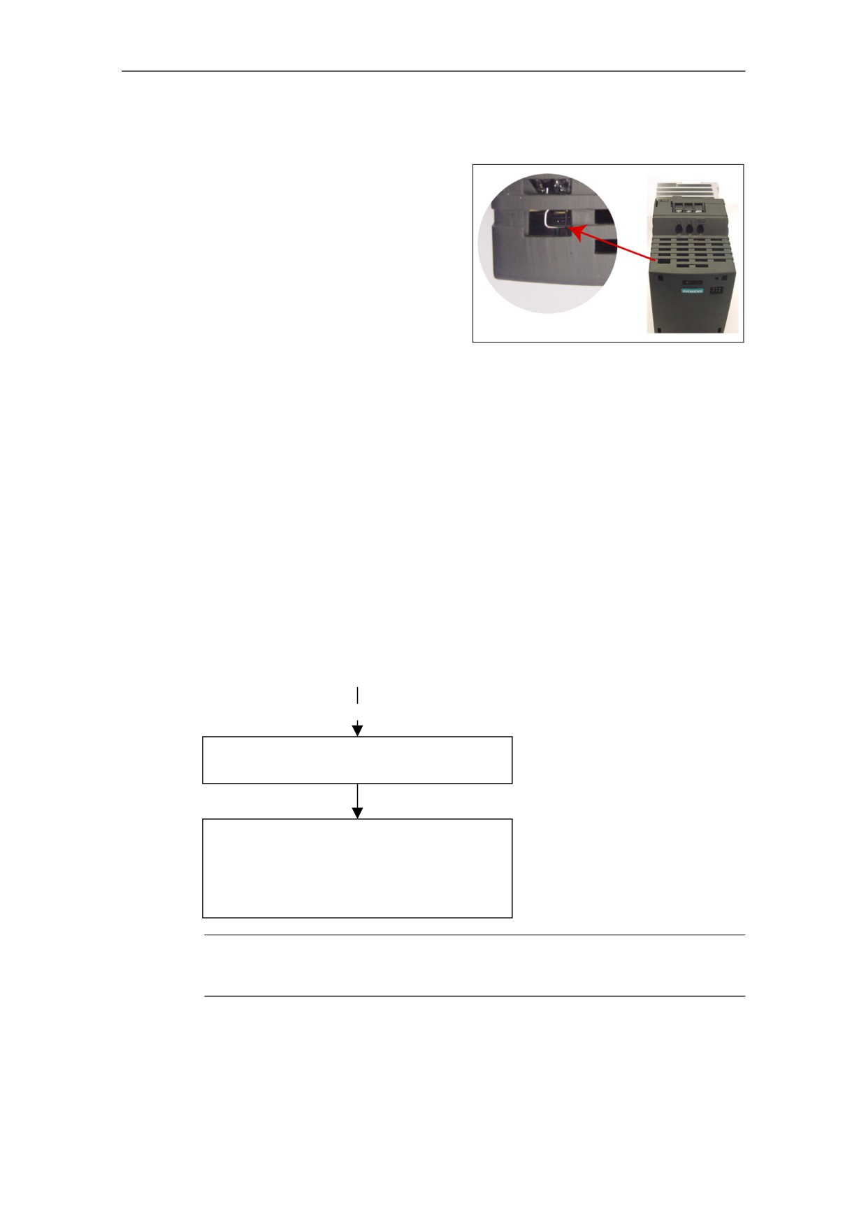
The supply frequency of the inverter
can be changed using either the
Operator Panel or by physically
cutting the Supply Frequency Link as
shown in Figure 3-4:
Cutting the supply link
The line supply frequency can be set
by cutting the supply link (see inset)
1. Ensure inverter is disconnected
from power supply.
Figure 3-4
Changing the Line Supply
Frequency
2. Carefully cut the link with an
appropriate pair of wire-cutters.
3. Inverter is now set for 60 Hz.
The inverter can be set back to 50 Hz, by setting P0100 = 0.
Using the Operator Panel
The supply frequency can be set by the following parameters:
Set P0100 = 0 (50 Hz) default
Set P0100 = 1 (60 Hz)
3.2.4
Commissioning Overview with the optional Operator Panel
Prerequisites
Mechanical and electrical Installation are completed.
Power ON
Quick Commissioning P0010 = 1
See Section 3.2.4.2
Further Commissioning via P0004 and P0003
An overview of the parameter structure is given in
Section 5.3
For a detailed description of the parameter, see the
Parameter List.
NOTE
We recommend the commissioning according this scheme. Nevertheless an expert
user is allowed to do the commissioning without the filter functions of P0004.
35
3 Commissioning
3.2.4.1
Commissioning with the Operator Panel
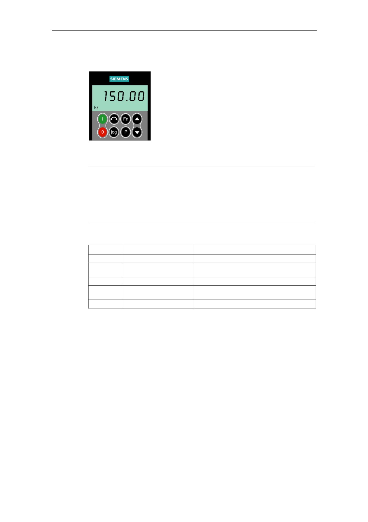
The Operator Panel (OP) provides access to the inverter
parameters and enables the user to customize the
settings of your MICROMASTER 410. The OP can be
used to configure several MICROMASTER 410 Inverters.
This is accomplished by using the OP to set the required
parameters and once the process is complete, then the
OP can be removed.
The OP contains a five-digit display that allows the user to
read and change parameter values. The OP does not
have the capability to store parameter information.
Table 3-2 shows the factory default settings for operation via the Operator Panel.
Notes
♦ The OP motor control functions are disabled by default. To control the motor
via the OP, parameter P0700 should be set to 1 and P1000 set to 1.
♦ The OP can be fitted to and removed from the inverter whilst power is
applied.
♦ If the OP has been set as the I/O control (P0700 = 1), the drive will stop if the
OP is removed.
Table 3-2
Default settings for operation using the OP
Parameter
Meaning
Default
P0100
Operating Mode Europe/US
50 Hz, kW
P0307
Power (rated motor)
Dimension (kW (Hp)) depending on setting of P0100.
[default value depending on variant.]
P0310
Motor frequency rating
50 Hz (60 Hz) depending on setting of P0100.
P0311
Motor speed rating
1395 (1680) rpm; depending on setting of P0100.
[default value depending on variant]
P1082
Maximum Motor Frequency
50 Hz (60 Hz) depending on setting of P0100.
36
3 Commissioning
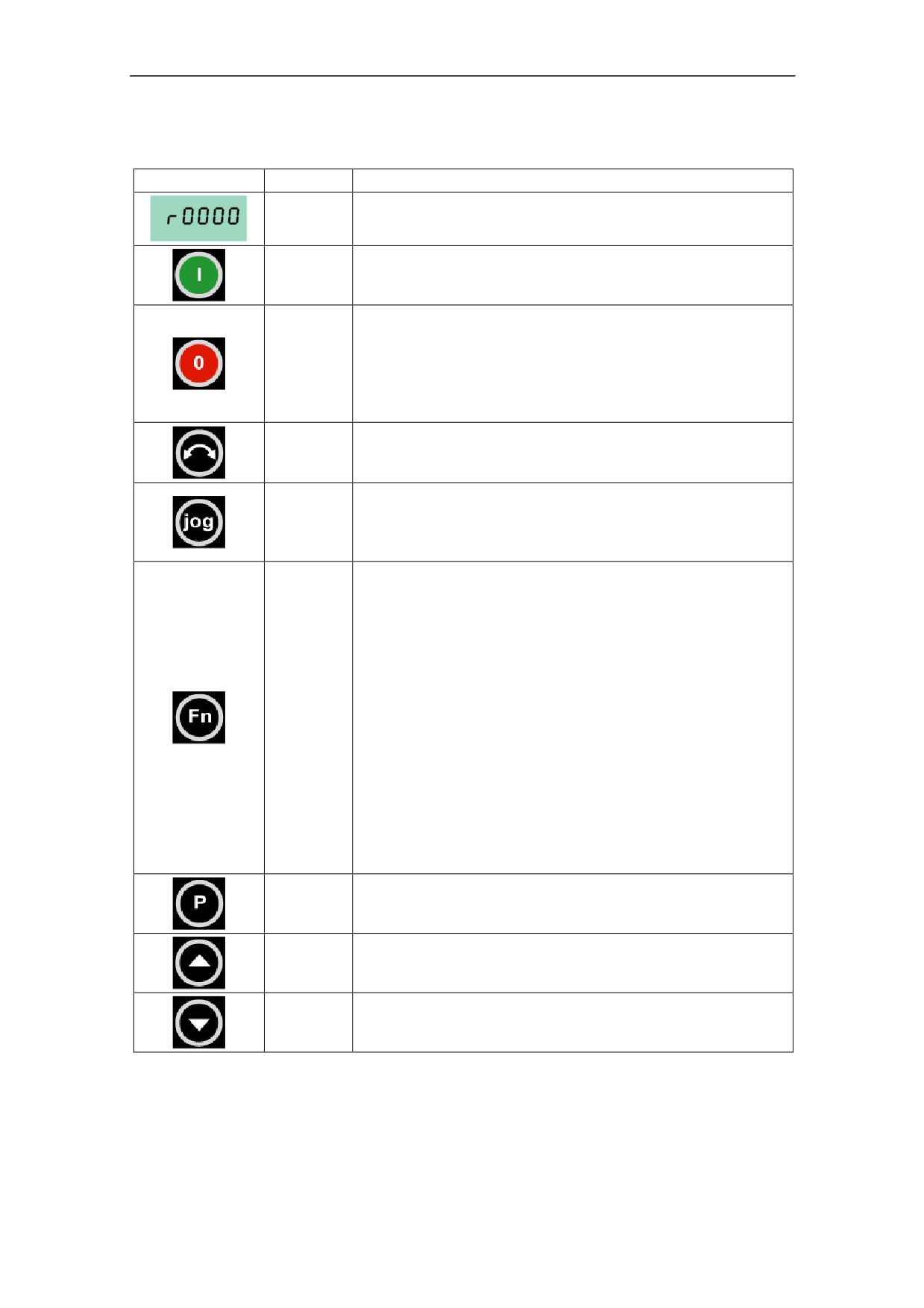
Buttons on the Operator Panel
Panel/Button
Function
Effects
Indicates
The LCD displays the settings currently used by the converter.
Status
Pressing the button starts the converter. This button is
Start motor
disabled by default. To enable this button set P0700 = 1.
OFF1
Pressing the button causes the motor to come to a
standstill at the selected ramp down rate. Disabled by
default; to enable set P0700 = 1.
Stop motor
OFF2
Pressing the button twice (or once long) causes the
motor to coast to a standstill.
This function is always enabled.
Press this button to change the direction of rotation of the
Change
motor. Reverse is indicated by a minus (-) sign or a flashing
direction
decimal point. Disabled by default, to enable set P0700 = 1.
Pressing this button while the inverter has no ON command
causes the motor to start and run at the preset jog frequency.
Jog motor
The motor stops when the button is released. Pressing this
button when the motor is running has no effect.
This button can be used to view additional information.
Pressing and holding the button for 2 seconds from any
parameter during operation, shows the following:
1. DC link voltage (indicated by d ñ units V).
2. Output frequency (Hz)
3. Output voltage (indicated by o ñ units V).
4. The value selected in P0005
Functions
Additional presses will toggle around the above displays.
A short press of the button will acknowledge a fault condition.
Jump Function
From any parameter (rXXXX or PXXXX) a short press of the
Fn button will immediately jump to r0000, you can then
change another parameter, if required. Upon returning to
r0000, pressing the Fn button will return you to your starting
point.
Access
Pressing this button allows access to the parameters.
parameters
Increase
Pressing this button increases the displayed value.
value
Decrease
Pressing this button decreases the displayed value.
value
Figure 3-5
Buttons on the Operator Panel
37
3 Commissioning
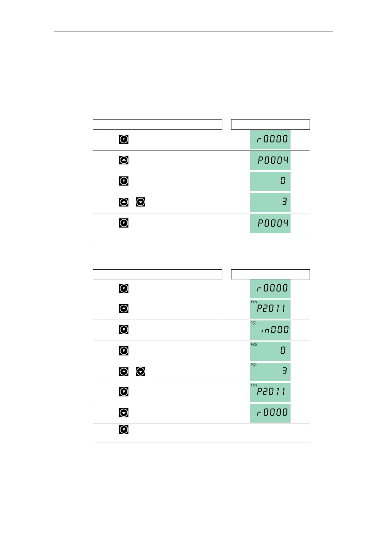
Changing parameters with the Operator Panel
The procedure for changing the value of parameter P0004 is described below.
Modifying the value of an indexed parameter is illustrated using the example of
P2011. Follow exactly the same procedure to alter other parameters that you wish
to set via the OP.
Changing P0004 ñ parameter filter function
Step
Result on display
1
Press
to access parameters
2
Press
until P0004 is displayed
3
Press
to access the parameter value level
4
Press
or
to the required value
5
Press
to confirm and store the value
6
Only the motor parameters are visible to the user.
Changing P2011 an indexed parameter
Setting USS address
Step
Result on display
1
Press
to access parameters
2
Press
until P2011 is displayed
3
Press
to access the parameter value level
4
Press
to display current set value
5
Press
or
to the required value
6
Press
to confirm and store the value
7
Press
until r0000 is displayed
8
Press
to return the display to the standard
drive display (as defined by the customer)
Figure 3-6
Changing parameters via the OP
38
3 Commissioning
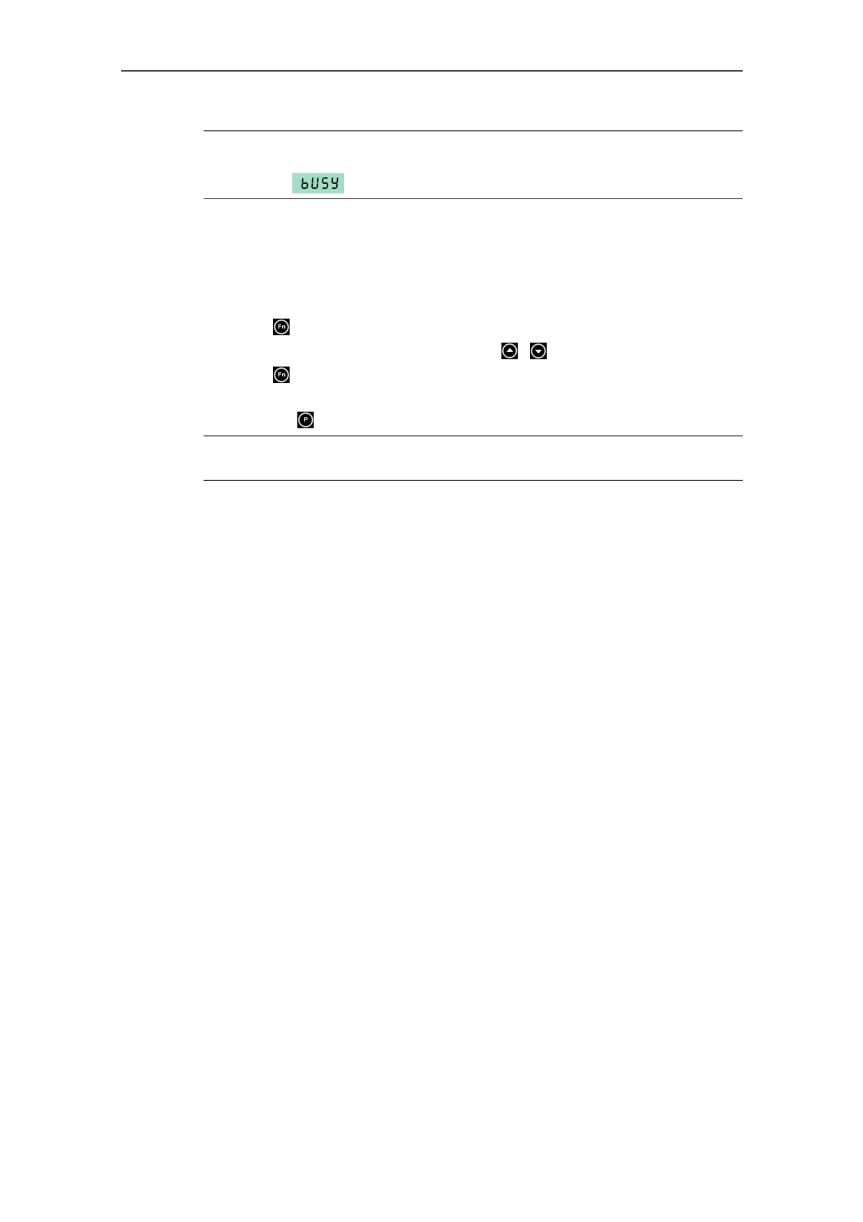
NOTE
In some cases - when changing parameter values - the display on the Operator
Panel shows
. This means the inverter is busy with tasks of higher priority.
Changing single digits in Parameter values
For changing the parameter value rapidly, the single digits of the display can be
changed by performing the following actions:
Ensure you are in the parameter value changing level (see "Changing parameters
with Operator Panel").
1. Press
(function button), which causes the right hand digit to blink.
2. Change the value of this digit by pressing
/
3. Press
(function button) again causes the next digit to blink.
4. Perform steps 2 to 4 until the required value is displayed.
5. Press the
to leave the parameter value changing level.
NOTE
The function button may also be used to acknowledge a fault condition
3.2.4.2
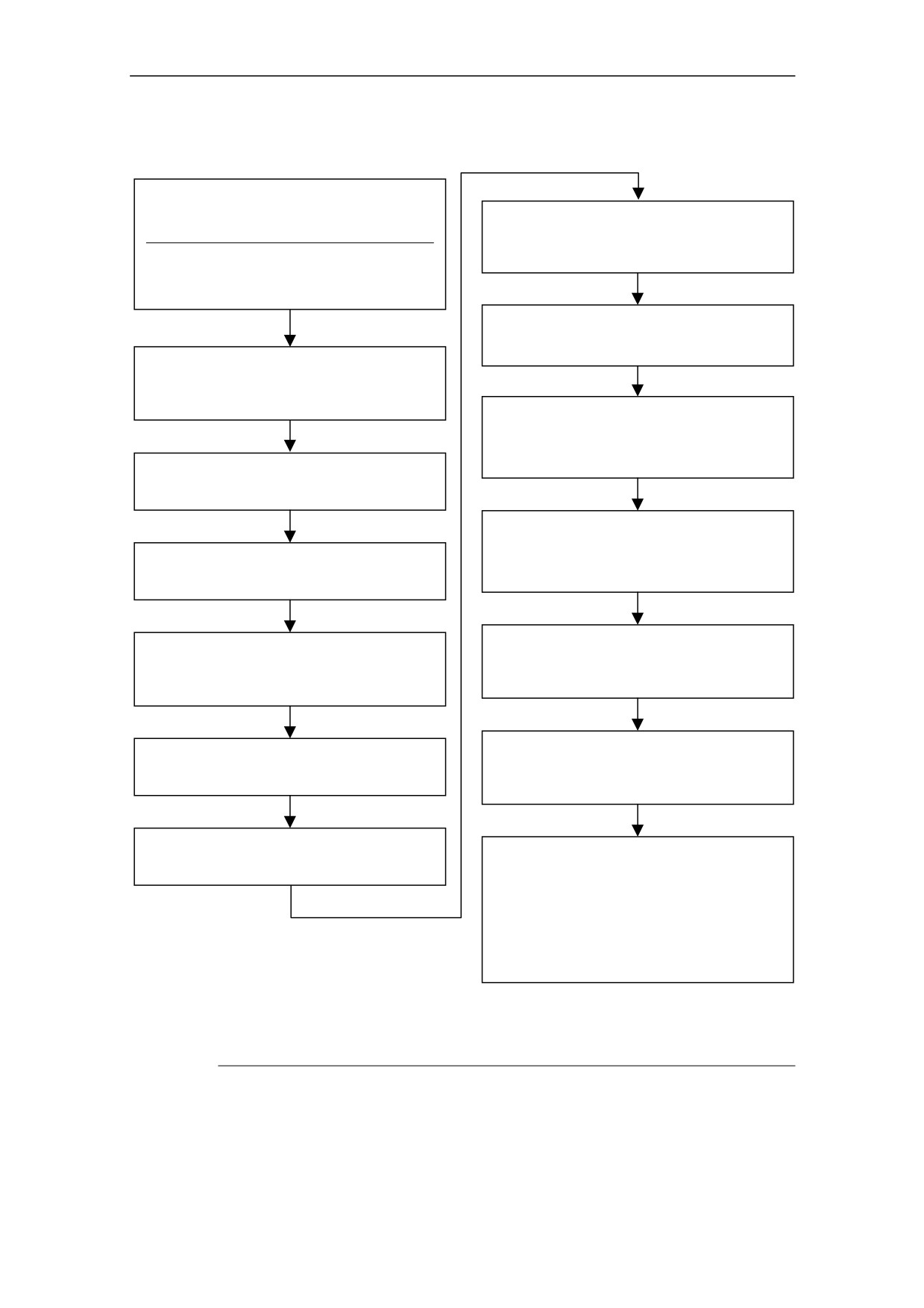
Quick commissioning (P0010=1)
It is important that parameter P0010 is used for commissioning and P0003 is used
to select the number of parameters to be accessed. This parameter allows a group
of parameters to be selected that will enable quick commissioning. Parameters
such as Motor settings and Ramp settings are included.
At the end of the quick commissioning sequence, P3900 should be selected,
which, when set to 1, will carry out the necessary motor calculations and clear all
other parameters (not included in P0010=1) to the default settings. This will only
happen in the Quick Commissioning mode.
39
3 Commissioning
Flow chart Quick Commissioning (Level 1 Only)
P0010 Start Quick Commissioning
0
Ready to Run
P0700 Selection of Command Source 2)
1
Quick Commissioning
(on / off / reverse)
30 Factory Setting
1
Operator Panel (OP)
Note
2
Terminal / Digital Inputs
P0010 must always be set back to '0' before
operating the motor. However if P3900 = 1 is set
after commissioning this is done automatically.
P1000 Selection of Frequency Setpoint 2)
1
OP frequency control ↑↓
2
Analogue Setpoint
P0100 Operation for Europe/N. America
0
Power in kW; f default 50 Hz
1
Power in hp; f default 60 Hz
2
Power in kW; f default 60 Hz
P1080 Min. Motor Frequency
Sets minimum motor frequency (0-650Hz) at which
the motor will run irrespective of the frequency
setpoint. The value set here is valid for both
P0304 Rated Motor Voltage1)
clockwise and anti-clockwise rotation.
Acceptable Range: 10 V - 2000 V
Nominal motor voltage (V) from rating plate
P1082 Max. Motor Frequency
Sets maximum motor frequency (0-650Hz) at which
P0305 Rated Motor Current1)
the motor will run at irrespective of the frequency
Acceptable Range: 0 - 2 x inverter rated current (A)
setpoint. The value set here is valid for both
Nominal motor current (A) from rating plate
clockwise and anti-clockwise rotation.
P1120 Ramp-Up Time
P0307 Rated Motor Power1)
Acceptable Range: 0 s - 650 s
Acceptable Range: 0 kW ñ 1.0 kW (0 hp ñ 1 hp)
Time taken for the motor to accelerate from
Nominal motor power (kW) from rating plate.
standstill up to maximum motor frequency.
If P0100 = 1, values will be in hp
P1121 Ramp-Down Time
P0310 Rated Motor Frequency1)
Acceptable Range: 0 s - 650 s
Acceptable Range: 12 Hz - 650 Hz
Time taken for motor to decelerate from maximum
Nominal motor frequency (Hz) from rating plate
motor frequency down to standstill.
P0311 Rated Motor Speed1)
P3900 End Quick Commissioning
Acceptable Range: 0 - 40000 1/min
0
End Quick Commissioning without motor
Nominal motor speed (rpm) from rating plate
calculation or factory reset.
1
End Quick Commissioning with motor
calculation and factory reset (Recommended)
2
End Quick Commissioning with motor
calculation and with I/O reset.
3
End Quick Commissioning with motor
calculation but without I/O reset.
1)
Motor related parameters ñ please refer to motor rating plate.
2)
Denotes parameters that contain more detailed lists of possible settings for use in specific
applications. Please refer to the Parameter List
40
3 Commissioning
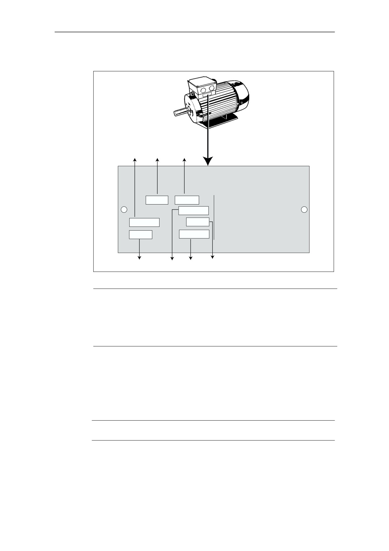
Motor data for parameterization
P0308
P0310
P0304
3_Mot
IEC 56
Nr. ED510 3053
12.022
IM B3
IP54
Rot KL 16
I.CI.F
50 Hz
230/400V
D/Y
60 Hz
440V Y
0.61 0.35 A
0.34A
0.14 kW
Cos j 0.81
0.12kW
Cos j
0.81
65%
2800 / min
3310 /min
S.F.
1.15
P0309
P0305
P0311
P0307
Figure 3-7
Typical Motor Rating Plate Example
NOTE
P0308 & P0309 are only visible if P0003 = 3. Only one of the parameters is
shown depending on the settings of P0100.
P0307 indicates kW or hp depending upon the setting of P0100. For detailed
information, please see the Parameter List.
Changing motor parameters is not possible unless P0010 = 1.
Ensure that the motor is configured correctly to the inverter (star/delta connection).
3.2.4.3
Reset to Factory default
To reset all parameters to the factory default settings; the following parameters
should be set as follows (the operator panel option is required):
1. Set P0010 = 30
2. Set P0970 = 1
NOTE
The reset process can take up to 3 minutes to complete.
41
3 Commissioning
3.3
General operation
For a full description of Level 1 to Level 3 parameters, please refer to the
Parameter List.
NOTICE
1. The inverter does not have a main power switch and is live when the mains
supply is connected. It waits, with the output disabled, until the RUN button is
pressed or for the presence of a digital ON signal at terminal 1.
2. If an OP is fitted and the output frequency is selected to be displayed (P0005
= 21) the corresponding setpoint is displayed approximately every 1.0
seconds while the inverter is stopped.
3. The inverter is programmed at the factory for standard applications on
Siemens four-pole standard motors that have the same power rating as the
inverters. When using other motors it is necessary to enter the specifications
from the motor's rating plate. See Figure 3-7 for details on how to read motor
data.
4. Changing motor parameters is not possible unless P0010 = 1.
5. You must set P0010 back to 0 in order to initiate a run.
Basic operation with the OP
Prerequisites
P0010 = 0 (in order to initiate the run command correctly).
P0700 = 1 (enables the start/stop button on the OP).
P1000 = 1 (this enables the motor potentiometer setpoints).
1. Press the green Button
to start the motor.
2. Press the Button
while the motor is turning. Motor speed increases to
50 Hz.
3. When the inverter reaches 50 Hz, press the Button . Motor speed and
displayed value are decreased.
4. Change the direction of rotation with the Button
5. The red button stops the motor
42
3 Commissioning
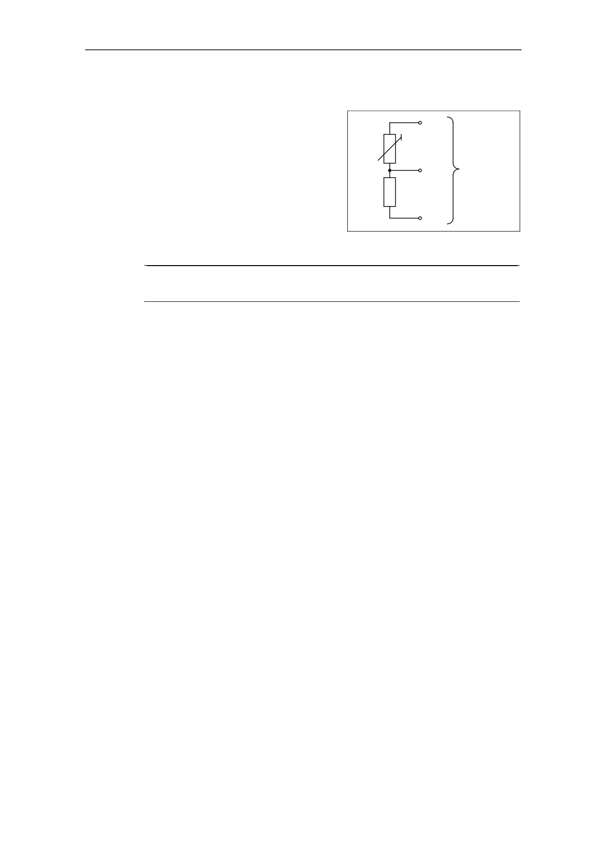
External motor thermal overload protection
When operated below rated speed, the
4
cooling effect of fans fitted to the motor
shaft is reduced. Consequentially, most
Motor
motors require de-rating for continuous
PTC
Inverter
operation at low frequencies. To ensure
1, 2
Control
that the motors are protected against
or 3
Terminals
overheating under these conditions, a
1 kΩ
PTC temperature sensor must be fitted to
the motor and connected to the inverter
5
control terminals as shown in Figure 3-8.
Figure 3-8
Motor Overload PTC
Connection
NOTE
To enable the trip function, set parameter P0701, P0702 or P0703 = 29.
43
4 Using the MICROMASTER 410
4
Using the MICROMASTER 410
WARNING
♦ When operating electrical devices, it is impossible to avoid applying
hazardous voltages to certain parts of the equipment.
♦ Emergency Stop facilities according to EN 60204 IEC 204 (VDE 0113) must
remain operative in all operating modes of the control equipment. Any
disengagement of the Emergency Stop facility must not lead to uncontrolled
or undefined restart.
♦ Wherever faults occurring in the control equipment can lead to substantial
material damage or even grievous bodily injury (i.e. potentially dangerous
faults), additional external precautions must be taken or facilities provided to
ensure or enforce safe operation, even when a fault occurs (e.g.
independent limit switches, mechanical interlocks, etc.).
♦ MICROMASTERS operate at high voltages.
♦ Certain parameter settings may cause the inverter to restart automatically
after an input power failure.
♦ Motor parameters must be accurately configured for motor overload
protection to operate correctly.
♦ This equipment is capable of providing internal motor overload protection in
accordance with UL508C section 42. Refer to P0610 and P0335, I2t is ON
by default.
♦ This equipment is suitable for use in a circuit capable of delivering not more
than 10,000 symmetrical amperes (rms), for a maximum voltage of
115 V/230 V, when protected by a H or K type fuse.
♦ This equipment must not be used as an ëemergency stop mechanismí (see
EN 60204, 9.2.5.4)
4.1
Frequency Setpoint (P1000)
Default:
Terminal 7 (AIN, 0Ö10 V corresponds to 0Ö50/60 Hz)
Other settings:
see P1000
45
4 Using the MICROMASTER 410
4.2
Command Sources (P0700)
NOTICE
The ramp times and ramp-smoothing functions also affect how the motor starts and
stops. For details of these functions, please refer to parameters P1120, P1121,
P1130 ñ P1134 in the Parameter List.
Starting the motor
Default:
Terminal 1 (DIN 1, high)
Other settings:
see P0700 to P0704
Stopping the motor
There are several ways to stop the motor:
Default:
♦ OFF1
Terminal 1 (DIN 1, low)
♦ OFF2
Off button on Operator Panel, pressing the Off button once
long (two seconds) or twice (with default settings)
♦ OFF3
no standard setting
Other settings:
see P0700 to P0704
Reversing the motor
Default:
Terminal 2 (DIN 2, high)
Other settings:
see P0700 to P0704
4.3
OFF and braking Functions
4.3.1
OFF1
This command (produced by canceling the ON command) causes the inverter to
come to a standstill at the selected ramp-down rate.
Parameter to change ramp-down time see P1121
NOTICE
ON and the following OFF1 command must have the same source.
If the ON/OFF1 command is set to more than one digital input, only the last set
digital input is valid e.g. DIN3 is active.
OFF1 can be combined with DC braking or Compound braking.
46
4 Using the MICROMASTER 410
4.3.2
OFF2
This command causes the motor to coast to a standstill (pulses disabled).
NOTICE
The OFF2 command can have one or more sources. By default the OFF2
command is set to Operator Panel. This source still exists even if other sources are
defined by one of the following parameters, P0700 to P0704 inclusive.
4.3.3
OFF3
An OFF3 command causes the motor to decelerate rapidly.
If a digital input is used as a source for OFF3, the digital input has to be closed
(high) in order to start the motor. If OFF3 is high, the motor can be started resp.
stopped by re-setting OFF1 or OFF2.
If OFF3 is low the motor cannot be started.
Ramp down time: see P1135
NOTICE
OFF3 can be combined with DC braking or Compound braking.
4.3.4
DC braking
DC braking is possible together with OFF1 and OFF3. A DC current is applied to
stop the motor quickly and hold the shaft stationary after the end of the braking
period.
Enable DC braking:
see P0701 to P0704
Set DC braking period:
see P1233
Set DC braking current:
see P1232
NOTICE
If no digital input is set to DC braking and P1233 ≠ 0, DC braking will be active after
every OFF1 command with the time set in P1233.
4.3.5
Compound Braking
Compound Braking is possible with both OFF1 and OFF3. For Compound Braking
a DC component is added to the AC current.
Set the braking current:
see P1236
47
4 Using the MICROMASTER 410
4.4
Control Modes (P1300)
The various modes of operation of the MICROMASTER 410 control the relation-
ship between the speed of the motor and the voltage supplied by the inverter. A
summary of the control modes available are listed below:
Linear V/f control,
P1300 = 0
Can be used for variable and constant torque applications, such as conveyors
and positive displacement pumps.
Linear V/f control with FCC (Flux Current Control),
P1300 = 1
This control mode can be used to improve the efficiency and dynamic
response of the motor.
Quadratic V/f control
P1300 = 2
This mode can be used for variable torque loads, such as fans and pumps.
Multi-point V/f control
P1300 = 3
For information regarding this mode of operation, please consult the MM410
Parameter List.
4.5
Faults and Alarms
Standard Inverter
If an Operator Panel is not fitted, the fault states and warnings are indicated by the
LED on the panel, see section 6.1 on page 57 for further information.
If the inverter is working correctly, the following LED sequence is visible:
Flashing Yellow (1000 ms on / 1000 ms off)
=
Ready to run
Continuous Yellow
= Run
Operator Panel Fitted
If an Operator Panel is fitted, the fault states (P0947) and warnings (P2110) are
displayed should a fault condition occur. For further details, please refer to the
Parameter List.
48
5 System Parameters
5
System Parameters
5.1
Introduction to MICROMASTER System Parameters
The parameters can only be changed by using the Operator Panel (OP) or the
Serial Interface.
Parameters can be changed and set using the OP to adjust the desired properties
of the inverter, such as ramp times, minimum and maximum frequencies etc. The
parameter numbers selected and the setting of the parameter values are indicated
on the optional five-digit LCD display.
rxxxx indicates a display parameter, Pxxxx a setting parameter.
P0010 initiates ìquick commissioningî.
The inverter will not run unless P0010 is set to 0 after it has been accessed.
This function is automatically performed if P3900 > 0.
P0004 acts as a filter, allowing access to parameters according to their
functionality.
If an attempt is made to change a parameter that cannot be changed in this
status, for example, cannot be changed whilst running or can only be changed
in quick commissioning, then
will be displayed.
Busy Message
In some cases - when changing parameter values - the display on the OP
shows
for maximum of five seconds. This means the inverter is busy
with tasks of higher priority.
5.1.1
Access Levels
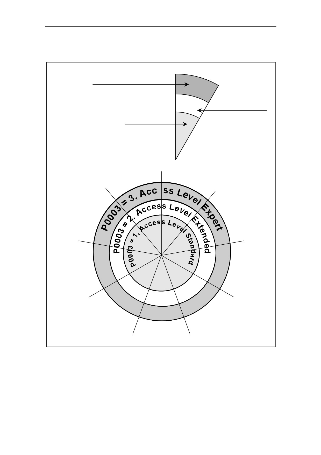
There are three access levels available to the user; Standard, Extended and
Expert. The level of access is set by parameter P0003. For most applications, the
Standard and Extended levels are sufficient.
The number of parameters that appear within each functional group (selected by
P0004) depends on the access level set in parameter P0003. For further details
regarding parameters, see the Parameter List.
49
5 System Parameters
5.2
Parameter Overview
P0004 = 10
Setpoint Channel
P0004 = 10, P0003 = 3
Parameters level 1, 2 and 3
Parameter accessed:
P1000, P1001, P1002, P1003, P1091 ...
P0004 = 10, P0003 = 2
P0004 = 0
Parameters level 1 and 2
(no filter function)
Parameter accessed:
P0004 = 10, P0003 = 1
allows direct access
P1000, P1001, P1002, P1003 ...
Parameters level 1
to the parameters,
Parameter accessed:
for the operating
P1000 ...
panel OP depending
on the selected
access level.
P0004 = 21
P0004 = 2
Alarms, Faults
Inverter Unit
& Monitoring
e
P0004 = 3
P0004 = 20
Motor Data
Communication
P0004 = 7
P0004 = 13
Commands and
Motor Control
Digtal I/O
P0004 = 12
P0004 = 8
Drive Features
Analogue I/O
P0004 = 10
Setpoint Channel &
Ramp Generator
Figure 5-1
Parameter Overview
50
5 System Parameters
5.3
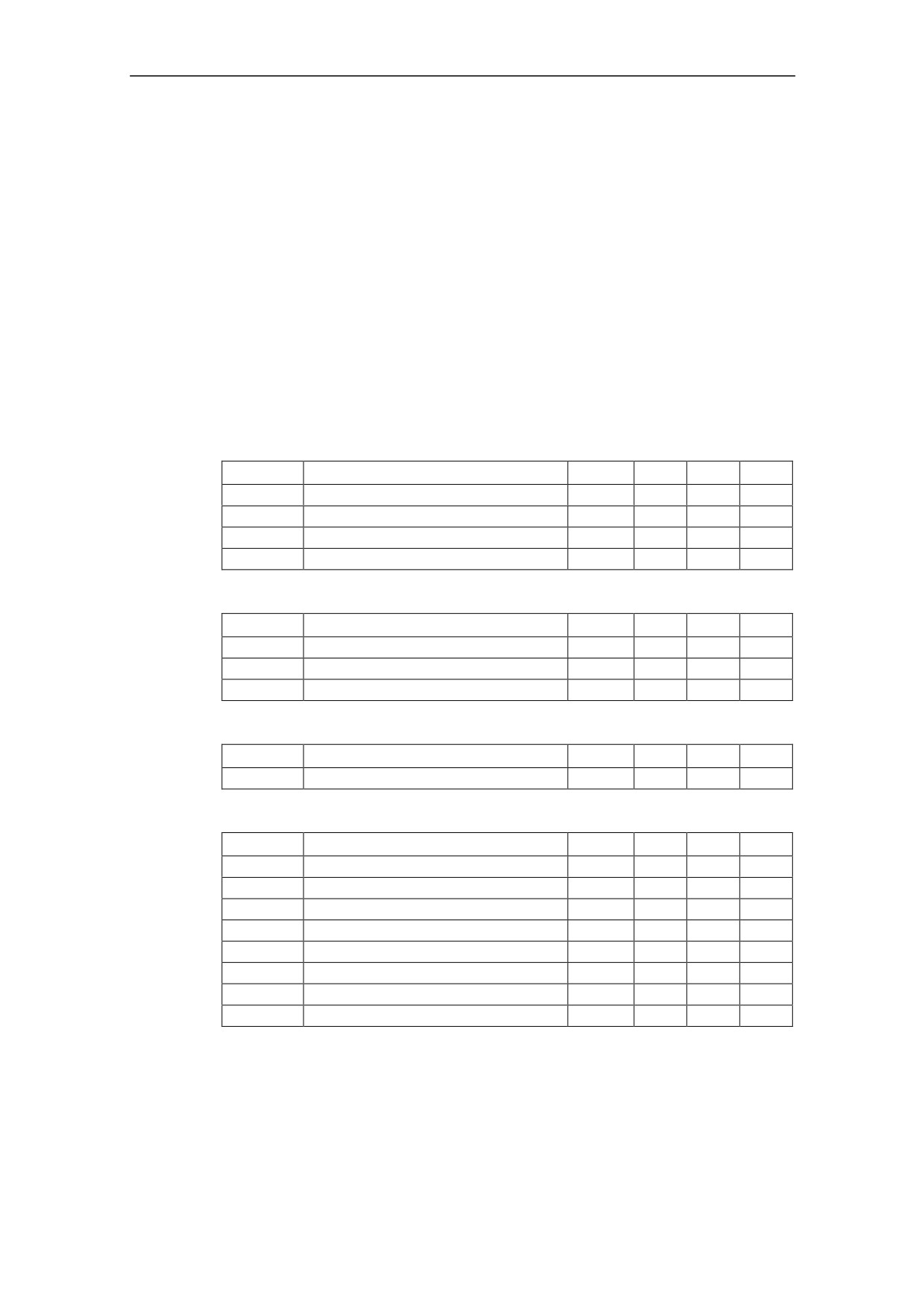
Parameter List (short form)
Explanatory information on following table:
Default:
Factory setting
Level:
Access level (Acc)
DS
Inverter status (Drive State), indicates the inverter state in which a
parameter can be modified (see P0010).
♦ C
Commissioning
♦ U
Run
♦ T
Ready to run
QC
Quick Commissioning
♦ Q
Parameter can be modified in the Quick Commissioning state.
♦ N
Parameter cannot be modified in the Quick Commissioning state.
Always
ParNr
ParText
Default
Acc
DS
QC
r0000
Drive display
-
1
-
-
P0003
User access level
1
1
CUT
N
P0004
Parameter filter
0
3
CUT
N
P0010
Commissioning parameter filter
0
1
CT
N
Quick Commissioning
ParNr
ParText
Default
Acc
DS
QC
P0100
Europe / North America
0
1
C
Q
P0101
Hidden Switch Setting
0
1
C
Q
P3900
End of quick commissioning
0
1
C
Q
Parameter Reset
ParNr
ParText
Default
Acc
DS
QC
P0970
Factory reset
0
1
C
N
Inverter Unit (P0004 = 2)
ParNr
ParText
Default
Acc
DS
QC
r0018
Firmware version
-
3
-
-
r0026
CO: Act. DC-link voltage
-
2
-
-
r0206
Rated inverter power [kW] / [hp]
-
3
-
-
r0207
Rated inverter current
-
3
-
-
r0209
Maximum inverter current
-
3
-
-
P0210
Supply voltage
230
3
CT
N
P0290
Inverter overload reaction
2
3
CT
N
P1800
Pulse frequency
4
3
CUT
N
51
5 System Parameters
Motor Data (P0004 = 3)
ParNr
ParText
Default
Acc
DS
QC
r0034
CO: Motor temperature (i2t)
-
3
-
-
P0300
Select motor type
1
3
C
Q
P0304
Rated motor voltage
230
1
C
Q
P0305
Rated motor current
3.25
1
C
Q
P0307
Rated motor power
0.75
1
C
Q
P0308
Rated motor cosPhi
0.000
3
C
Q
P0309
Rated motor efficiency
0.0
3
C
Q
P0310
Rated motor frequency
50.00
1
C
Q
P0311
Rated motor speed
0
1
C
Q
P0335
Motor cooling
0
3
CT
Q
P0340
Calculation of motor parameters
0
3
CT
N
P0610
Motor I2t temperature reaction
2
3
CT
N
P0611
Motor I2t time constant
100
3
CT
N
P0614
Motor I2t overload warning level
100.0
3
CUT
N
P0640
Motor overload factor [%]
190.0
3
CUT
Q
P1910
Select motor data identification
0
2
CT
Q
Commands and Digital I/O (P0004 = 7)
ParNr
ParText
Default
Acc
DS
QC
r0002
Drive state
-
3
-
-
r0019
CO/BO: BOP control word
-
3
-
-
r0052
CO/BO: Act. Status word 1
-
2
-
-
r0053
CO/BO: Act. Status word 2
-
2
-
-
r0054
CO/BO: Act. Control word 1
-
3
-
-
r0055
CO/BO: Add. Act. Control word
-
3
-
-
P0700
Selection of command source
2
1
CT
Q
P0701
Function of digital input 1
1
2
CT
N
P0702
Function of digital input 2
12
2
CT
N
P0703
Function of digital input 3
9
2
CT
N
P0704
Function of digital input 4
0
2
CT
N
P0719[2]
Selection of cmd. & freq. Setp.
0
3
CT
N
r0722
CO/BO: Binary input values
-
3
-
-
P0724
Debounce time for digital inputs
3
3
CT
N
P0731
BI: Function of digital output 1
52:3
2
CUT
N
r0747
CO/BO: State of digital outputs
-
3
-
-
P0748
Invert digital outputs
0
3
CUT
N
P0810
BI: CDS bit 0 (Local / Remote)
0:0
3
CUT
N
52
5 System Parameters
Analogue I/O (P0004 = 8)
ParNr
ParText
Default
Acc
DS
QC
r0752
Act. input of ADC [V]
-
3
-
-
P0753
Smooth time ADC
3
3
CUT
N
r0754
Act. ADC value after scaling [%]
-
2
-
-
P0757
Value x1 of ADC scaling [V]
0
3
CUT
N
P0758
Value y1 of ADC scaling
0.0
3
CUT
N
P0759
Value x2 of ADC scaling [V]
24
3
CUT
N
P0760
Value y2 of ADC scaling
100.0
3
CUT
N
P0761
Width of ADC deadband [V]
0
3
CUT
N
Setpoint Channel and Ramp Generator (P0004 = 10)
ParNr
ParText
Default
Acc
DS
QC
P1000
Selection of frequency setpoint
2
1
CT
Q
P1001
Fixed frequency 1
0.00
2
CUT
N
P1002
Fixed frequency 2
5.00
2
CUT
N
P1003
Fixed frequency 3
10.00
2
CUT
N
r1024
CO: Act. Fixed frequency
-
3
-
-
P1031
Setpoint memory of the MOP
0
2
CUT
N
P1032
Inhibit reverse direction of MOP
1
3
CT
N
P1040
Setpoint of the MOP
5.00
3
CUT
N
P1070
CI: Main setpoint
755:0
3
CT
N
P1071
CI: Main setpoint scaling
1:0
3
CT
N
P1075
CI: Additional setpoint
0:0
3
CT
N
r1078
CO: Total frequency setpoint
-
3
-
-
P1080
Min. frequency
0.00
1
CUT
Q
P1082
Max. frequency
50.00
1
CT
Q
P1091
Skip frequency 1
0.00
3
CUT
N
P1120
Ramp-up time
10.00
1
CUT
Q
P1121
Ramp-down time
10.00
1
CUT
Q
P1130
Ramp-up initial rounding time
0.00
3
CUT
N
P1131
Ramp-up final rounding time
0.00
3
CUT
N
P1132
Ramp-down initial rounding time
0.00
3
CUT
N
P1133
Ramp-down final rounding time
0.00
3
CUT
N
P1134
Rounding type
0
3
CUT
N
P1135
OFF3 ramp-down time
5.00
3
CUT
Q
r1170
CO: Frequency setpoint after RFG
-
3
-
-
53
5 System Parameters
Drive Features (P0004 = 12)
ParNr
ParText
Default
Acc
DS
QC
P0005
Display selection
21
2
CUT
N
P1200
Flying start
0
3
CUT
N
P1202
Motor-current: Flying start
100
3
CUT
N
P1203
Search rate: Flying start
100
3
CUT
N
P1210
Automatic restart
1
2
CUT
N
P1215
Holding brake enable
0
3
T
N
P1216
Holding brake release delay
1.0
3
T
N
P1217
Holding time after ramp down
1.0
3
T
N
P1232
DC braking current
100
3
CUT
N
P1233
Duration of DC braking
0
3
CUT
N
P1236
Compound braking current
0
3
CUT
N
P1240
Configuration of Vdc controller
1
3
CT
N
Motor Control (P0004 = 13)
ParNr
ParText
Default
Acc
DS
QC
r0020
CO: Act. frequency setpoint
-
2
-
-
r0021
CO: Act. frequency
-
2
-
-
r0022
Act. rotor speed
-
3
-
-
r0024
CO: Act. output frequency
-
3
-
-
r0025
CO: Act. output voltage
-
3
-
-
r0056
CO/BO: Status of motor control
-
2
-
-
r0067
CO: Act. output current limit
-
3
-
-
P1300
Control mode
0
2
CT
Q
P1310
Continuous boost
50.0
2
CUT
N
P1311
Acceleration boost
0.0
3
CUT
N
P1312
Starting boost
0.0
2
CUT
N
P1316
Boost end frequency
20.0
3
CUT
N
P1320
Programmable V/f freq. coord. 1
0.00
3
CT
N
P1321
Programmable V/f volt. coord. 1
0.0
3
CUT
N
P1322
Programmable V/f freq. coord. 2
0.00
3
CT
N
P1323
Programmable V/f volt. coord. 2
0.0
3
CUT
N
P1324
Programmable V/f freq. coord. 3
0.00
3
CT
N
P1325
Programmable V/f volt. coord. 3
0.0
3
CUT
N
P1333
Start frequency for FCC
10.0
3
CUT
N
P1335
Slip compensation
0.0
3
CUT
N
P1340
Imax controller prop. gain
0.000
3
CUT
N
54
5 System Parameters
Communication (P0004 = 20)
ParNr
ParText
Default
Acc
DS
QC
P0927
Parameter changeable via
15
3
CUT
N
r0964[5]
Firmware version data
-
3
-
-
P0971
Transfer data from RAM to EEPROM
0
3
CUT
N
P2000
Reference frequency
50.00
3
CT
N
P2009[2]
USS normalization
0
3
CT
N
P2010[2]
USS baudrate
6
3
CUT
N
P2011[2]
USS address
0
3
CUT
N
P2012[2]
USS PZD length
2
3
CUT
N
P2013[2]
USS PKW length
127
3
CUT
N
P2014[2]
USS telegram off time
0
3
CT
N
r2015[4]
CO: PZD from BOP link (USS)
-
3
-
-
P2016[4]
CI: PZD to BOP link (USS)
52:0
3
CT
N
r2018[4]
CO: PZD from COM link (USS)
-
3
-
-
P2019[4]
CI: PZD to COM link (USS)
52:0
3
CT
N
r2024[2]
USS error-free telegrams
-
3
-
-
r2025[2]
USS rejected telegrams
-
3
-
-
r2026[2]
USS character frame error
-
3
-
-
r2027[2]
USS overrun error
-
3
-
-
r2028[2]
USS parity error
-
3
-
-
r2029[2]
USS start not identified
-
3
-
-
r2030[2]
USS BCC error
-
3
-
-
r2032
BO: CtrlWrd1 from BOP link (USS)
-
3
-
-
r2031[2]
USS length error
-
3
-
-
r2033
BO: CtrlWrd2 from BOP link (USS)
-
3
-
-
r2036
BO: CtrlWrd1 from COM link (USS)
-
3
-
-
r2037
BO: CtrlWrd2 from COM link (USS)
-
3
-
-
Alarms, Faults and Monitoring (P0004 = 21)
ParNr
ParText
Default
Acc
DS
QC
P0952
Total number of faults
0
3
CT
N
r0947[8]
Last fault code
-
2
-
-
r2110[4]
Warning number
-
3
-
-
r2114[2]
Run time counter
-
3
-
-
P2167
Switch-off frequency f_off
1.00
3
CUT
N
55
6 Troubleshooting
6
Troubleshooting
WARNING
♦ Repairs on equipment may only be carried out by Siemens Service, by repair
centers authorized by Siemens or by qualified personnel who are thoroughly
acquainted with all the warnings and operating procedures contained in this
manual.
♦ Any defective parts or components must be replaced using genuine Siemens
authorised parts.
♦ Risk of electric shock. The DC link capacitors remain charged for five minutes
after power has been removed. It is not permissible to open the equipment
until 5 minutes after the power has been removed.
6.1
Troubleshooting with the Standard Inverter LED
The following is a description of the fault and warning indications given by the LED
on the Standard Inverter:
Inverter Off/No supply:
No LED lit.
Power On/Ready:
1000 ms On / 1000 ms Off
Inverter Running OK:
Steady LED
General Warning:
500 ms On / 200 ms Off
Fault Condition:
100 ms On / 100 ms Off
6.2
Troubleshooting with the Operator Panel (OP)
If the display shows a fault or warning code, please refer to Section 6.3.
If the motor fails to start when the ON command has been given:
Check that P0010 = 0.
Check that a valid ON signal is present.
Check that P0700 = 2 (for digital input control) or
P0700 = 1 (for OP control).
Check that the setpoint is present (0 to 10V on Terminal 7) or the setpoint has
been entered into the correct parameter, depending upon the setpoint source
(P1000). See the Parameter List for further details.
If the motor fails to run after changing the parameters, set P0010 = 30 then P0970
= 1 and press P to reset the inverter to the factory default parameter values.
Now use a switch between cobtrol terminals 1 and 4. The drive should now run to
the defined setpoint by analogue input.
NOTICE
Motor data must relate to the inverter data power range and voltage.
57

6 Troubleshooting
6.3
Fault messages
Fault
Possible Causes
Diagnose & Remedy
Reac-
tion
F0001
Motor power (P0307) does not
Check the following:
OFF2
OverCurrent
correspond to the inverter power
1. Motor power (P0307) must correspond to
(r0206)
inverter power (r0206).
Motor lead short circuit
2. Cable length limits must not be exceeded.
Earth faults
3. Motor cable and motor must have no short-
circuits or earth faults
4. Motor parameters must match the motor in
use
5. Motor must not be obstructed or overloaded.
Increase the ramp time
Reduce the boost level
F0002
Overvoltage can be caused either
Check the following:
OFF2
OverVoltage
by too high main supply voltage
1. Supply voltage (P0210) must lie within limits
or if motor is in regenerative
indicated on the inverter rating plate.
mode.
2. DC-link voltage controller must be enabled
Regenerative mode can be
(P1240) and parameterized properly.
caused by fast ramp downs or if
the motor is driven from an active
3. Ramp-down time (P1121) must match inertia
load.
of load.
NOTE
Higher inertia requires longer ramp times
F0003
Main supply failed.
Check the following:
OFF2
UnderVoltage
Shock load outside specified
1. Supply voltage (P0210) must lie within limits
limits.
indicated on the inverter rating plate.
2. Supply must not be susceptible to temporary
failures or voltage reductions.
F0004
Ventilation inadequate
Check the following:
OFF2
Inverter Over
Ambient temperature is too high.
1. Pulse frequency must be set to default value
Temperature
2. Ambient temperature could be higher than
specified for the inverter
F0005
Inverter overloaded.
Check the following:
OFF2
Inverter I2t
Duty cycle too demanding.
1. Load duty cycle must lie within specified
limits.
Motor power (P0307) exceeds
inverter power capability ( r0206).
2. Motor power (P0307) must match inverter
power (r0206)
F0011
Motor overloaded
Check the following:
OFF1
Motor Over
1. Load duty cycle must be correct
Temperature
I
2t
2. Motor temperatur warning level (P0604) must
match.
F0041
Stator resistance measurement
Check if the motor is connected to the
OFF2
failure
inverter.
Check that the motor data have been entered
correctly.
F0051
Read or write failure while saving
Factory Reset and new parameterization
OFF2
Parameter
non-volatile parameter.
Change drive
EEPROM Fault
F0052
Read failure for power stack
Change drive
OFF2
power stack
information or invalid data.
Fault
58

6 Troubleshooting
Fault
Possible Causes
Diagnose & Remedy
Reac-
tion
F0060
Internal communications failure
If fault persists, change inverter
OFF2
Asic Timeout
Contact Service Department
F0071
No setpoint values from USS during
Check USS master
OFF2
USS (BOP-
telegram off time
link) setpoint
fault
F0072
No setpoint values from USS during
Check USS master
OFF2
USS (COMM
telegram off time
link) setpoint
fault
F0085
External fault triggered via terminal
Disable terminal input for fault trigger.
OFF2
External Fault
inputs
F0101
Software error or processor failure
Cycle through power (on/off).
OFF2
Stack
Replace drive if fault is not corrected.
Overflow
F0450
Selftest failed
Drive may run but some features will not work
OFF2
BIST Tests
properly.
Failure
Replace drive.
(Service Mode
Only)
59
6 Troubleshooting
6.4
Alarms
Alarm
Possible Causes
Diagnose & Remedy
Reac-
tion
A0501
Motor power does not
Check the following:
--
Current Limit
correspond to the inverter power
1.
Motor power (P0307) must correspond to
Motor leads are too long
inverter power (r0206).
Earth faults
2.
Cable length limits must not be exceeded.
3.
Motor cable and motor must have no short-
circuits or earth faults
4.
Motor parameters must match the motor in
use
5.
Motor must not be obstructed or overloaded
Increase the ramp-up-time.
Reduce the boost.
A0502
Overvoltage limit is reached.
If this warning is displayed permanently, check
--
Overvoltage
drive input voltage .
This warning can occur during
limit
ramp down, if the dc-link con-
troller is disabled (P1240 = 0).
A0503
Main supply failed
Check main supply voltage (P0210).
--
UnderVoltage
Limit
A0504
Warning level of inverter heat-sink
Check the following:
--
Inverter Over
temperature (P0614) is exceeded,
1.
Ambient temperature must lie within
Temperature
resulting in pulse frequency reduction
specified limits
and/or output frequency reduction
(depending on parametrization in
2.
Load conditions and duty cycle must be
(P0610)
appropriate
A0505
Warning level exceeded, current will
Check that duty cycle lies within specified limits
--
Inverter I2t
be reduced if parameterized
(P0610 = 1)
A0506
Difference between heatsink and
Check that duty cycle and shock loads lie within
--
Inverter duty
IGBT junction temperature exceeds
specified limits
cycle
warning limits
A0511
Motor overloaded.
Check the following:
--
Motor Over
Load duty cycle too high.
1.
P0611 (motor I2t time constant) should be
Temperature
set to appropriate value
I
2t
2.
P0614 (Motor I2t overload warning level)
should be set to suitable level
A0600
Software problem
Contact Service Department
--
RTOS Overrun
Warning
A0910
Vdc max controller has been de-
Check the following:
--
Vdc-max
activated
1.
Input voltage must lie within range.
controller de-
Occurs if main supply voltage is
activated
2.
Load must be matched.
permanently too high.
3.
In certain cases apply braking resistor.
Occurs if motor is driven by an
active load, causing motor to go
into regenerative mode.
Occurs at very high load inertias,
when ramping down.
A0911
Vdc max controller is active; so ramp-
Check the inverter input voltage (P0210)
--
Vdc-max
down times will be increased
controller
automatically to keep DC-link voltage
active
(r0026) within limits
60

6 Troubleshooting
Alarm
Possible Causes
Diagnose & Remedy
Reac-
tion
A0920
ADC parameters should not be set to
Check P0757, P0758, P0759 and P0760
--
ADC
identical values, since this would
parameters
produce illogical results.
not set
properly.
A0922
No Load is applied to the inverter.
Check that a load has been applied to the
--
No load
inverter.
As a result, some functions may not
applied to
work as under normal load conditions.
inverter
61
7 MICROMASTER 410 Specifications
7
MICROMASTER 410 Specifications
Table 7-1
MICROMASTER 410 Performance Ratings
Feature
Specification
Mains Operating Voltage &
100 to 120 V ± 10% 1AC
0.12 kW ñ 0.55 kW
Power Ranges
200 to 240 V ± 10% 1AC
0.12 kW ñ 0.75 kW
Input Frequency
47 to 63 Hz
Output frequency
0 Hz - 650 Hz
Power Factor
≥ 0.95
Inverter Efficiency
96 to 97 %
Up to 150 % of rated output current for 60 seconds followed by 85 % of rated
Overload Capability
output current for 240 seconds (cycle time 300 seconds)
Inrush Current
Less than rated input current
Control Method
Linear V/f ; Parabolic V/f; Flux Current Control (FCC); Multi-point V/f
Pulse Frequency
2 kHz to 16 kHz (2 kHz steps)
8 kHz Standard
Fixed Frequencies
3; programmable
Skip Frequencies
1; programmable
Setpoint Resolution
0.01Hz digital, 0.01 Hz serial, 10 bit analogue
(motor potentiometer 0.1 Hz)
Output Frequency Resolution
0.01 Hz digital, 0.01 Hz serial
Digital Inputs (PNP type)
3; freely programmable, non isolated, SIMATIC compatible
Analog Input
1; for setpoint (0 to 10 V, scalable or for use as 4th digital input)
Relay Output
1; parameterizable, 30 V DC / 5 A (resistive), 250 V AC / 2 A (inductive)
Serial Interface
RS-485, for operation with USS protocol
Electromagnetic Compatibility
Variant with integrated EMC filter according to EN 61800-3
Braking
DC braking and Compound braking
Protection Level
IP20
Operation Temperature
-10 °C to +50 °C
Storage Temperature
-40 °C to +70 °C
Humidity
95 % RH ñ non-condensing
Operational Altitudes
Up to 1000 m above sea level without derating
Protection Features
Undervoltage, Overvoltage, Overload, Ground Faults, Short circuit, Stall
Prevention, Motor Overtemperature, Inverter Overtemperature Protection
Standards
UL, cUL, CE, C-tick
CE Marked
Conformity with EC Low Voltage Directive 73/23/EEC
filtered variants are also conform to Electromagnetic Compatibility Directive
89/336/EEC
Design/Manufacture
In accordance with ISO 9001
63
7 MICROMASTER 410 Specifications
Table 7-2
Terminal Torques ñ Field Wiring Connectors
Motorside PE
All other terminals
terminal
[Nm]
0.8
1.1
Tightening Torque
[lbf.in]
7.1
9.8
Table 7-3
MICROMASTER 410 Specifications
Input voltage range
1 AC 200 V ñ 240 V, ± 10 % (with built in Class B Filter)
Order No.
6SE6410-
2BB11
2BB12
2BB13
2BB15
2BB17
-2AA0
-5AA0
-7AA0
-5BA0
-5BA0
[kW]
0.12
0.25
0.37
0.55
0.75
Motor Output Rating
[hp]
0.16
0.33
0.5
0.75
1.0
Output Current Max.
[A]
0.9
1.7
2.3
3.2
4.2
Input Current
[A]
1.5
3.0
4.4
5.8
7.8
10
10
10
10
16
Recommended Fuse
[A]
3NA3803 3NA3803 3NA3803 3NA3803 3NA3805
[mm2]
1.0
1.0
1.0
1.0
1.5
Input Cable Min.
[awg]
16
16
16
16
14
[mm2]
2.5
2.5
2.5
2.5
2.5
Input Cable Max.
[awg]
12
12
12
12
12
[mm2]
1.0
1.0
1.0
1.0
1.0
Output Cable Min.
[awg]
16
16
16
16
16
[mm2]
2.5
2.5
2.5
2.5
2.5
Output Cable Max.
[awg]
12
12
12
12
12
[kg]
0.8
0.8
0.8
1.0
1.0
Weight
[lbs]
1.8
1.8
1.8
2.2
2.2
w [mm]
69.0
69.0
69.0
69.0
69.0
h [mm]
150.0
150.0
150.0
150.0
150.0
d [mm]
118.0
118.0
118.0
138.0
138.0
Dimensions
w [inches]
2.72
2.72
2.72
2.72
2.72
h [inches]
5.90
5.90
5.90
5.90
5.90
d [inches]
4.65
4.65
4.65
5.43
5.43
64
7 MICROMASTER 410 Specifications
Input voltage range
1 AC 200 V ñ 240 V, ± 10 % (Unfiltered)
Order No.
6SE6410-
2UB11
2UB12
2UB13
2UB15
2UB17
-2AA0
-5AA0
-7AA0
-5BA0
-5BA0
[kW]
0.12
0.25
0.37
0.55
0.75
Motor Output Rating
[hp]
0.16
0.33
0.5
0.75
1.0
Output Current Max.
[A]
0.9
1.7
2.3
3.2
4.2
Input Current
[A]
1.5
3.0
4.4
5.8
7.8
10
10
10
10
16
Recommended Fuse
[A]
3NA3803 3NA3803 3NA3803 3NA3803 3NA3805
[mm2]
1.0
1.0
1.0
1.0
1.5
Input Cable Min.
[awg]
16
16
16
16
14
[mm2]
2.5
2.5
2.5
2.5
2.5
Input Cable Max.
[awg]
12
12
12
12
12
[mm2]
1.0
1.0
1.0
1.0
1.0
Output Cable Min.
[awg]
16
16
16
16
16
[mm2]
2.5
2.5
2.5
2.5
2.5
Output Cable Max.
[awg]
12
12
12
12
12
[kg]
0.8
0.8
0.8
1.0
1.0
Weight
[lbs]
1.8
1.8
1.8
2.2
2.2
w [mm]
69.0
69.0
69.0
69.0
69.0
h [mm]
150.0
150.0
150.0
150.0
150.0
d [mm]
118.0
118.0
118.0
138.0
138.0
Dimensions
w [inches]
2.72
2.72
2.72
2.72
2.72
h [inches]
5.90
5.90
5.90
5.90
5.90
d [inches]
4.65
4.65
4.65
5.43
5.43
Input voltage range
1 AC 100 V ñ 120 V, ± 10 % (Unfiltered)
Order No.
6SE6410-
2UA11
2UA12
2UA13
2UA15
-2AA0
-5AA0
-7AA0
-5BA0
[kW]
0.12
0.25
0.37
0.55
Motor Output Rating
[hp]
0.16
0.33
0.5
0.75
Output Current Max.
[A]
0.9
1.7
2.3
3.2
Input Current
[A]
4.6
7.5
10.1
13.4
10
10
16
20
Recommended Fuse
[A]
3NA3803 3NA3803 3NA3805 3NA3807
[mm2]
1.0
1.0
1.5
2.5
Input Cable Min.
[awg]
16
16
14
12
[mm2]
2.5
2.5
2.5
2.5
Input Cable Max.
[awg]
12
12
12
12
[mm2]
1.0
1.0
1.0
1.0
Output Cable Min.
[awg]
16
16
16
16
[mm2]
2.5
2.5
2.5
2.5
Output Cable Max.
[awg]
12
12
12
12
[kg]
0.8
0.8
0.8
1.0
Weight
[lbs]
1.8
1.8
1.8
2.2
w [mm]
69.0
69.0
69.0
69.0
h [mm]
150.0
150.0
150.0
150.0
d [mm]
118.0
118.0
118.0
138.0
Dimensions
w [inches]
2.72
2.72
2.72
2.72
h [inches]
5.90
5.90
5.90
5.90
d [inches]
4.65
4.65
4.65
5.43
65
8 Options
8
Options
The following accessories are available as options for your MICROMASTER
MM410 Inverter. For more details please refer to the catalogue or contact your
local Siemens sales office if you require assistance.
8.1
Variant Independent Options
Operator Panel (OP)
DIN Rail Mounting Kit
PC to inverter connection kit
Software commissioning tools:
♦ ìDriveMonitorî
♦ ìStarterî
8.2
Variant Dependent Options
Low leakage Class B filter
Line commutating choke
67
9 Electro-Magnetic Compatibility
9
Electro-Magnetic Compatibility (EMC)
9.1
Electro-Magnetic Compatibility (EMC)
All manufacturers / assemblers of electrical apparatus which ìperforms a complete
intrinsic function and is placed on the market as a single unit intended for the end
userî must comply with the EMC directive EEC/89/336.
There are two routes for the manufacturer/assembler to demonstrate compliance:
9.1.1
Self-Certification
This is a manufacturer's declaration that the European standards applicable to the
electrical environment for which the apparatus is intended have been met. Only
standards that have been officially published in the Official Journal of the European
Community can be cited in the manufacturer's declaration.
9.1.2
Technical Construction File
A technical construction file can be prepared for the apparatus describing its EMC
characteristics. This file must be approved by a ëCompetent Bodyí appointed by the
appropriate European government organization. This approach allows the use of
standards that are still in preparation.
NOTE
However, MICROMASTER 410 is designed to be used only by professional
endusers with EMC knowledge. It is not designed for users having no EMC
knowledge.
In any case this operating instructions cover sufficient information which enables
the professional enduser to implement from his side all measures to ensure
electromagnetical compatibility.
69
9 Electro-Magnetic Compatibility
9.1.3
EMC Directive Compliance with Harmonics Regulations
From 1st January 2001 all electrical apparatus covered by the EMC Directive will
have to comply with EN 61000-3-2 "Limits for harmonic current emissions
(equipment input ≤ 16 A per phase)".
All Siemens variable speed drives of the MICROMASTER, MIDIMASTER,
MICROMASTER Eco and COMBIMASTER ranges, which are classified as
"Professional Equipment" within the terms of the standard, fulfill the requirements
of the standard.
Special considerations for 250 W to 550 W drives with 230 V 1ac mains supplies
when used in non-industrial applications
For units in this voltage and power range the following warning applies:
îThis equipment requires supply authority acceptance for connection to the public
supply networkî. Please refer to EN 61000-3-12 sections 5.3 and 6.4 for further
information. Units connected to Industrial Networks1 do not require connection
approval (see EN 61800-3, section 6.1.2.2).
The harmonic current emissions from these products are described in the table
below:
Rating
Typical Harmonic
Typical Harmonic
Typical Voltage
Current (A)
Current (%)
Distortion
Distribution Transformer
Rating
10kVA
100kVA
1MVA
3rd
5th
7th
9th
11th
3rd
5th
7th
9th
11th
THD (%)
THD (%)
THD (%)
250W 230V 1ac
2.40
1.70
0.95
0.40
0.20
83
59
33
14
7
0.67
0.067
0.0067
370W 230V 1ac
3.50
2.50
1.40
0.60
0.25
85
61
34
15
6
0.97
0.097
0.0097
550W 230V 1ac
4.60
3.30
1.80
0.70
0.40
87
62
34
13
8
1.27
0.127
0.0127
The allowed harmonic currents for ìprofessional equipmentî with an input power
> 1 kW are not yet defined. Therefore, any electrical apparatus containing the
above drives which has an input power > 1 kW will not require connection
approval.
Alternatively, the necessity to apply for connection approval can be avoided by
fitting the input chokes recommended in the technical catalogues (except 550 W
230 V 1ac units).
1 Industrial Networks are defined as those which do not supply buildings used for domestic purposes.
70
9 Electro-Magnetic Compatibility
9.1.4
General cases of EMC performance
Three General cases of EMC performance are available as detailed below:
Case 1: General Industrial
Compliance with the EMC Product Standard for Power Drive Systems EN 61800-3
for use in Second Environment (Industrial) and Restricted Distribution.
Table 9-1
Case 1 - General Industrial
EMC Phenomenon
Standard
Level
Emissions:
Radiated Emissions
EN 55011
Level group 1, class A
Conducted Emissions
EN 61800-3
Limits are weaker as EN55011, class A,
group 1
Immunity:
Electrostatic Discharge
EN 61000-4-2
8 kV air discharge
Burst Interference
EN 61000-4-4
2 kV power cables (Level 3),
1 kV control (Level 3)
Radio Frequency Electromagnetic Field
EN61000-4-3
26-1000 MHz, 10 V/m
Case 2: Filtered Industrial
This level of performance will allow the manufacturer/assembler to self-certify their
apparatus for compliance with the EMC directive for the industrial environment as
regards the EMC performance characteristics of the power drive system.
Performance limits are as specified in the Generic Industrial Emissions and
Immunity standards EN 50081-2 and EN 61000-6-2.
Table 9-2
Case 2 - Filtered Industrial
EMC Phenomenon
Standard
Level
Emissions:
Radiated Emissions
EN 55011
Level group 1, class A
Conducted Emissions
EN 61800-3
Level are weaker as EN55011 class A,
group 1
Immunity:
Supply Voltage Distortion
EN 61000-2-4
Voltage Fluctuations, Dips, Unbalance,
EN 61000-2-1
Frequency Variations
Electrostatic Discharge
EN 61000-4-2
8 kV air discharge
Burst Interference
EN 61000-4-4
2 kV power cables (Level 3),
2 kV control (Level 4)
Radio Frequency Electromagnetic
EN 61000-4-3
80-1000 MHz, 10 V/m, 80% AM,
Field, amplitude modulated
power and signal lines
71
9 Electro-Magnetic Compatibility
Case 3: Filtered - for residential, commercial and light industry
This level of performance will allow the manufacturer / assembler to self-certify
compliance of their apparatus with the EMC directive for the residential,
commercial and light industrial environment as regards the EMC performance
characteristics of the power drive system. Performance limits are as specified in
the generic emission and immunity standards EN 50081-1 and EN 50082-1.
Table 9-3
Case 3 - Filtered for Residential, Commercial and Light Industry
EMC Phenomenon
Standard
Level
Emissions:
Radiated Emissions*
EN 55022
Level for equipment class B
Conducted Emissions
EN 61800-3
category C1: level according EN 55011,
class B
category C2: level according EN55011,
class A
Immunity:
Supply Voltage Distortion
EN 61000-2-4
Voltage Fluctuations, Dips, Unbalance,
EN 61000-2-1
Frequency Variations
Electrostatic Discharge
EN 61000-4-2
8 kV air discharge
Burst Interference
EN 61000-4-4
2 kV power cables (Level 3),
2 kV control (Level 4)
* These limits are dependent on the inverter being correctly installed inside a
metallic switchgear enclosure. The limits will not be met if the inverter is not
enclosed.
NOTICE
To achieve these performance levels, you must not exceed the default Pulse
frequency nor use cables longer than 5 m (16.40 ft).
Table 9-4
Compliance Table
Model
Remarks
Case 1 ñ General Industrial
6SE6410-2U***-**A0
Unfiltered units, all voltages and powers. The product standard EN 61800-3
+ A11 for ìAdjustable speed electrical power drive systems ñ Part3: EMC
product standard including specific test methodsî specifies limits for
conducted emissions, which cannot be matched from unfiltered inverters in
the 2nd environment.
If compliance with the product standard is required, filtered inverters ( as
described under case 2) have to be installed.
Case 2 ñ Filtered Industrial
6SE6410-2B***-**A0
All units with integral filters for screened motor cables up to 10 m (32,80 ft)
[Class A]
72

9 Electro-Magnetic Compatibility
Case 3 ñ Filtered for residential, commercial and light industry
6SE6410-2B***-**A0
category C12: All units with integral filters for screened motor cables up to 5
m (16.40 ft) [Class B]
category C23: All units with integral filters for screened motor cables up to
10 m (32.80 ft) [Class A
In addition a warning label will be required:
ìThis is a product of category C2 according to IEC 61800-3. In a domestic
environment this product may cause radio interference in which case
mitigation measures may be required.î
* denotes any value is allowed.
2 category C1: Power Drive system (PDS) of rated voltage less than 1000V,
intended for use in the first environment.
3 category C2: Power Drive System (PDS) of rated voltage less than 1000V, which
when used in the first environment is intended to be installed and commissioned
only by a professional.
73
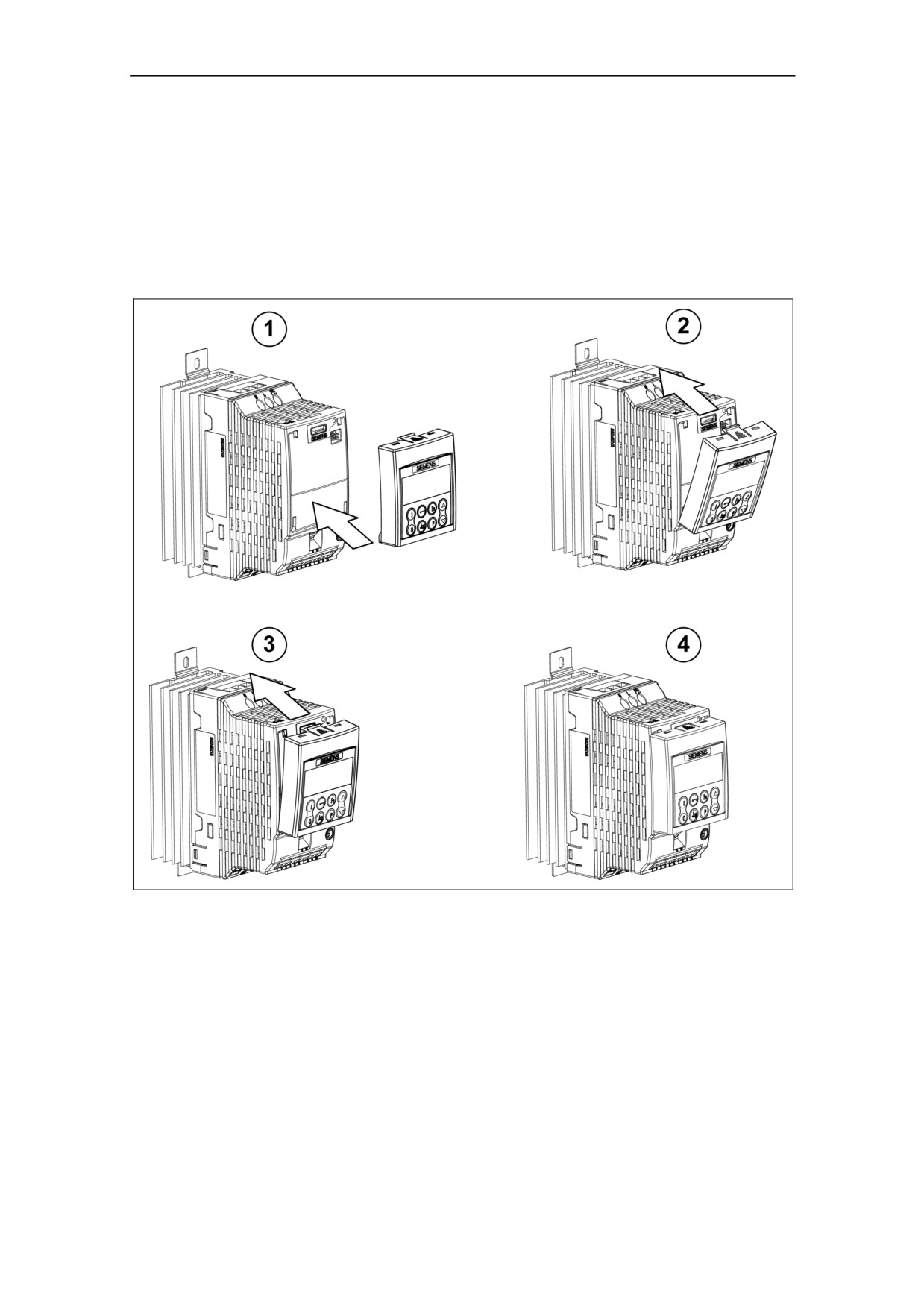
Fitting the Operator Panel
Appendices
A
Fitting the Operator Panel
75
Applicable Standards
B
Applicable Standards
European Low Voltage Directive
The MICROMASTER product range complies with the requirements of the Low
Voltage Directive 73/23/EEC as amended by Directive 98/68/EEC. The units are
certified for compliance with the following standards:
EN 50178
Electronic equipment for use in power installations
EN 60204-1
Safety of machinery - Electrical equipment of machines
European EMC Directive
When installed according to the recommendations described in this manual, the
MICROMASTER fulfils all requirements of the EMC Directive as defined by the
EMC Product Standard for Power Drive Systems EN61800-3.
Underwriters Laboratories
UL and CUL LISTED POWER CONVERSION EQUIPMENT 5B33 for use in a
pollution degree 2
ISO 9001
Siemens plc operates a quality management system, which complies with the
requirements of ISO 9001.
Notice:
Machinery Directive
The devices are suitable for installation in machines. According to the machinery
directive 89/392/EC the compliance requires a separate certificate of conformity.
This certificate must be issued by the firm which constructs the plant or puts the
machinery on the market.
76
List of Abbreviations
C
List of Abbreviations
AC
Alternating Current
AIN
Analog Input
CT
Constant Torque
DC
Direct Current
DIN
Digital Input
EEC
European Economic Community
ELCB
Earth Leakage Circuit Breaker
EMC
Electro-Magnetic Compatibility
EMI
Electro-Magnetic Interference
FAQ
Frequently Asked Question
FCC
Flux Current Control
FCL
Fast Current Limitation
IGBT
Insulated Gate Bipolar Transistor
I/O
Input and Output
LCD
Liquid Crystal Display
LED
Light Emitting Diode
OP
Operator Panel
PLC
Programmable Logic Controller
PTC
Positive Temperature Coefficient
RCCB
Residual Current Circuit Breaker
RCD
Residual Current Device
RPM
Revolutions Per Minute
77
Index
Index
A
EMC Directive Compliance
70
EMC performance
Access Levels
49
filtered for residential, commercial and
Altitude
19
light industry
72
filtered industrial class
71
Ambient operating conditions
19
general industrial class
71
Applicable standards
EMI
29
European EMC Directive
74
European Low Voltage Directive
74
External motor thermal overload protection
ISO 9001
74
.............................................................. 43
Underwriters Laboratories
74
F
Atmospheric pollution
20
Fault codes
B
with the Operator Panel fitted
57
with the Standard Inverter LED
57
Basic operation
34
changing parameters with OP
38
Faults and warnings
external motor thermal overload
OP fitted
48
protection
41, 43
Standard Inverter
48
general
42
Features
15
with OP
42
Fitting the Operator Panel
73
C
Flux Current Control
48
Foreword
5
Changing the Line Supply Frequency
35
Frequency Setpoint
45
Commissioning
31
Front Panels
33
Compound Braking
47
Contact address
5
H
Control Modes
48
Harmonic Currents
D
tables
21
Humidity Range
19
DC braking
47
I
Default settings
34, 36
Dimensions and Torques
23
Installation
17
DIN Rail Mounting
25
after a period of storage
18
Drill pattern for MICROMASTER 410
22
Installation and cooling
20
Internet Home Address
5
E
Inverter block diagram
32
Electrical Installation
26
L
Electro-Magnetic Compatibility
general
69
Linear V/f control
48
self-certification
69
Long cables
technical construction file
69
operation with
27
Electro-Magnetic Interference
29
M
avoiding EMI
29
Electromagnetic radiation
20
Main characteristics
15
EMC
69
Mechanical Installation
22
78
Index
MICROMASTER 410
Quick commissioning
39
available options
67
R
general
15
main characteristics
15
Reset to Factory default
41
performance characteristics
16
Residual Current Device
protection characteristics
16
operation with
27
specifications
63
Motor connections
27
S
Motor data
41
Safety instructions
7
Multi-point V/f control
48
Shock
20
O
Specifications
64
Status Display
34
Operation
starting and stopping the motor
46
T
Operation with
Technical Support
5
long cables
27
Residual Current Device
27
Temperature
19
ungrounded IT supplies
26
Terminal Torques
64
Operator Panel
36
Troubleshooting
57
changing the operator panel
73
U
default settings
36
warnings and faults states
34
Ungrounded (IT) supplies
Operator panels
operation with
26
Overview
15
V
P
Variant Dependent Options
67
Parameters
Variant Independent Options
67
changing parameters with OP
38
Vibration
20
system parameters
49
W
Performance characteristics
16
Performance Ratings
63
Warnings, cautions & notes
Power and motor connections
27
commissioning
8
single phase
29
definitions
6
dismantling & disposal
9
Power connections
27
general
7
Power Losses
operation
9
output graphs
19
repair
9
Protection characteristics
16
transport & storage
8
Q
Water hazard
20
Wiring Guidelines EMI
30
Quadratic V/f control
48
Qualified personnel
6
79

Suggestions and/or Corrections
To:
Suggestions
Siemens AG
Automation & Drives Group
Corrections
SD VM 4
P.O. Box 3269
For Publication/Manual:
MICROMASTER 410
D-91050 Erlangen
Federal Republic of Germany
Email:
Technical.documentation@con.siemens.co.uk
User Documentation
Operating Instructions
From
Name:
Order Number:
Date of Issue:
04/02
Company/Service Department
Should you come across any printing
errors when reading this publication,
Address:
please notify us on this sheet.
Suggestions for improvement are also
welcome.
Telephone: __________ /
Telefax: ________ /
81
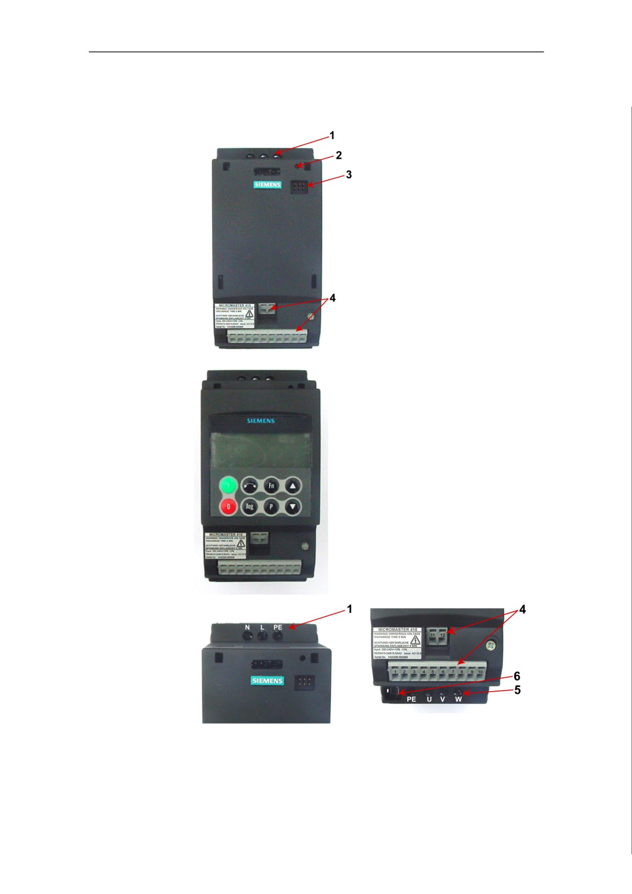
View of Units
View of Unit
Key:
1. Line Terminals
2. Status LED
Standard Inverter
3. Operator Panel Connector
4. Control Terminals
5. Motor Terminals
6. DC+/DC- Terminals
Inverter with
Optional
Operator Panel
Fitted
Connections &
Terminals
83